

Page 1
PosiDRIVE Security Gate
Installation, Operation, and
Maintenance Manual
Page 2

Page 3

Safety Notice
COPYRIGHT
PosiDRIVE Security Gate
Ver si on 6
ZMA-330
© 2008-2009 Federal APD, Inc. All rights reserved. No part of this publication may be reproduced, transmitted, transcribed, stored in a retrieval system, or translated into any language in any form by any means without the written permission of
Federal APD, Incorporated.
Printing Date
First Version..............................................July 2000
Second Version..........................................December 2000
Third Version.............................................February 2001
Fourth Version...........................................July 2001
Fifth Version..............................................December 2003
Sixth Version.............................................June 2009
To reduce the risk of severe personal injury or damage to equipment, turn off
the power to the equipment before performing any maintenance or repairs.
Failure to heed this warning could result in injury or even death of those who
come in contact with the product.
People’s lives and property depend on your safe installation and maintenance of equipment. Listed below are
some important safety instructions and precautions which you should follow when working on any
equipment. Failure to follow all safety precautions and instructions can result in serious injury or property
APD
damage. Refer to the specific operational manual for a particular piece of equipment before beginning any
service work.
❑ Frequently inspect the equipment to ensure that it is operating properly.
❑ Ensure that maintenance is performed by the factory or an authorized distributor at least twice a year.
Safety Hints
❑ Use vibrant colors on parking equipment at entrance lanes and exit lanes.
❑ Always provide proper signage, both on the roadway and on other equipment.
❑ Maintain the manufacturer’s warning stickers on gate arms and on other equipment.
❑ Encourage the use of safety devices such as buzzers or flashing lights.
❑ Always recommend that sidewalks be parallel to entrance lanes and exit lanes.
Federal
Safety Notice
To prevent injury to pedestrians, maintenance personnel, persons on bicycles or motorcycles, monitor all activity
in relation to entrance and exit lanes to ensure barrier gates are not accidentally lowered or raised. Take special
care when commanding any equipment action from a centralized computer system, especially when the control
equipment is not in your line of vision.
Use Pictograms
Federal APD, Inc. recommends using universally identifiable icons, or pictograms, in all entrance and exit lanes,
roadways, posts and walls. Paint “No Pedestrian” pictogram on the roadway adjacent to the parking barrier gate.
Pictograms depicting “No Motorcycles,” “No Wheelchairs,” “No Bicycles,” and “No Trucks” are also
recommended.
Safety Is Good Business
As an institution, municipality, or private operator, it is important to be aware of the potential liabilities which
may arise in normal parking operations. Adapting a “Safety First” attitude provides your business and your
patrons with a safer environment. After all, safety is good business!
Page 4

Warranty Information
Federal APD, Inc. warrants that the Products will be free from any defects in material and workmanship under normal use and service, wear and tear excepted, for a period of two years from the
date of shipment from Federal APD. Exceptions to this warranty may include any products and/or
accessories that are used with Federal APD equipment but are not manufactured by Federal APD
Inc. In those instances where Federal APD is not the manufacturer of goods sold hereunder, Federal APD's warranty shall be the lesser of such manufacturers' warranty, or Federal APD's standard
warranty.
This warranty shall not apply to Products which have not been properly maintained or have been
subjected to misuse, neglect, accident or damage, or which have been modified, changed, or
reworked in any way, without prior written approval of Federal APD. Federal APD's sole obligation shall be to repair or replace, at Federal APD's option, any defective part or parts within such
two year period. Upon Federal APD's written instructions, allegedly defective goods shall be
returned to Federal APD for inspection. This warranty extends only to the original purchaser from
Distributor/Dealer and shall not cover repair, labor, or replacement of parts that are by nature
expendable. Distributor/Dealer agrees to deliver the Federal APD Limited Warranty then in effect
to each of its customers at the time of the sale. Distributor/Dealer shall have no authority to bind
Federal APD to any warranty beyond that extended therein. All Products are subject to design and/
or appearance modifications which are production standards at the time of shipment. Federal APD
may, but shall not be required to, modify or update Products shipped prior to a current production
standard.
THERE ARE NO OTHER WARRANTIES, EXPRESSED OR IMPLIED, INCLUDING BUT
NOT LIMITED TO ANY IMPLIED WARRANTIES OF MERCHANTABILITY OR FITNESS
FOR A PARTICULAR PURPOSE. IN NO EVENT SHALL FEDERAL APD BE LIABLE FOR
ANY LOSS OF PROFITS OR ANY INDIRECT OR CONSEQUENTIAL DAMAGES ARISING
OUT OF FEDERAL APD'S BREACH OF THIS WARRANTY OR ANY OTHER TERM OR
CONDITION OF THIS AGREEMENT.
Page 5

Table of Contents
CHAPTER 1
Introduction .................................................................................................................................... 1
PosiDRIVE Security Gate Operational Overview.....................................................................2
Manual Operation................................................................................................................2
Automatic Operation ........................................................................................................... 2
Free Mode ..................................................................................................................... 3
Pay Mode ......................................................................................................................4
Pay/Free Mode.............................................................................................................. 5
Power Failure Detection...................................................................................................... 6
PosiDRIVE Structural Overview...............................................................................................6
Gate Enclosure (Cabinet) .................................................................................................... 6
Mechanical Components ..................................................................................................... 7
Drive Mechanism .............................................................................................................. 10
Electrical Components....................................................................................................... 10
Gate Arm ...........................................................................................................................13
PosiDRIVE Controller.......................................................................................................14
DIP Switches...............................................................................................................15
Inputs........................................................................................................................... 15
Outputs........................................................................................................................ 16
Opening the Enclosure Door.................................................................................................... 16
Removing the Enclosure Cap................................................................................................... 16
CHAPTER 2
Installation..................................................................................................................................... 19
Installation Overview............................................................................................................... 20
Installing the Enclosure............................................................................................................20
Wiring the Gate........................................................................................................................23
Installing the Gate Arm............................................................................................................ 25
Install a Standard Gate Arm .............................................................................................. 26
Install a Folding Gate Arm ................................................................................................27
Change the Gate Arm Configuration................................................................................. 34
Setting the Mainsprings ...........................................................................................................38
Disabling the Locked-Down Feature (Optional) .....................................................................40
Setting the DIP Switches.......................................................................................................... 42
CHAPTER 3
Maintenance and Repair.............................................................................................................. 45
Maintenance and Repair Overview..........................................................................................46
Performing Preventive Maintenance........................................................................................ 46
Grease Mainshaft Bearings................................................................................................47
Grease the Connection Rod Bearings................................................................................47
Troubleshooting a Problem...................................................................................................... 48
Locking, Unlocking, and Advancing the Gate Arm ................................................................ 49
Adding, Removing, or Replacing the Mainsprings.................................................................. 52
Aligning the Drive Mechanism................................................................................................ 54
PosiDRIVE Security Gate ZMA-330, Ver. 6 Table of Contents • i
Page 6

APPENDIX A
Product Support............................................................................................................................57
Getting Help .............................................................................................................................58
Accessing the Distributor Resource Center..............................................................................59
APPENDIX B
Order and Repair Procedures .....................................................................................................61
Placing an Order.......................................................................................................................62
Requesting a Repair..................................................................................................................62
Locate a Part Number ........................................................................................................63
Mainsprings.................................................................................................................64
Enclosure.....................................................................................................................65
Electrical Components ................................................................................................68
Standard Gate Arm......................................................................................................70
Folding Gate Arm........................................................................................................73
Drive Mechanism ........................................................................................................78
Index ..............................................................................................................................................83
ii • Table of Contents ZMA-330, Ver.6 PosiDRIVE Security Gate
Page 7

List of Figures
Figure 1.1 Free Gate with Opening Loop...................................................................................... 3
Figure 1.2 Pay Gate ....................................................................................................................... 4
Figure 1.3 Pay/Free Gate ............................................................................................................... 5
Figure 1.4 Enclosure Components................................................................................................. 7
Figure 1.5 Mechanical Components .............................................................................................. 8
Figure 1.6 Electrical Components ............................................................................................... 11
Figure 1.7 Standard Gate Arm..................................................................................................... 13
Figure 1.8 Folding Gate Arm....................................................................................................... 14
Figure 1.9 PosiDRIVE Controller ............................................................................................... 14
Figure 1.10 Draw Latch............................................................................................................... 17
Figure 2.1 PosiDRIVE Security Gate Footprint Dimensions...................................................... 21
Figure 2.2 Gate Cabinet Warning Label (Part # 20-3469) .......................................................... 22
Figure 2.3 Wiring with the Federal APD Detector Harness........................................................ 24
Figure 2.4 Wiring with a Non-Federal APD Detector Harness................................................... 25
Figure 2.5 Standard Gate Arm Installation.................................................................................. 26
Figure 2.6 Gate Arm Warning Label (Part # 20-4343) ............................................................... 27
Figure 2.7 Dimensions for Folding Gate Arm Mounting Hole ................................................... 28
Figure 2.8 Installing the Cable Tower ......................................................................................... 29
Figure 2.9 Attaching the Fixed Section of the Folding Gate Arm to the Gate Flange................ 30
Figure 2.10 Attaching the Folding Section to the Gate Arm Stabilizer....................................... 31
Figure 2.11 Attaching the Stabilized Folding Section to the Gate Arm Fixed Secton................ 32
Figure 2.12 Attaching the Cable Turnbuckle to the Gate Arm.................................................... 33
Figure 2.13 Gate Arm Configuration Components ..................................................................... 34
Figure 2.14 Pivot Bar................................................................................................................... 35
Figure 2.15 Set Screws ................................................................................................................ 36
Figure 2.16 Mainshaft Removal .................................................................................................. 36
Figure 2.17 Spring Adjustment Bolts .......................................................................................... 39
Figure 2.18 Down Bump Stop ..................................................................................................... 41
Figure 2.19 DIP switches in the Open Position........................................................................... 42
Figure 3.1 Motor Crank Position when the Gate Arm is Down .................................................. 51
Figure 3.2 Motor Crank Position when the Gate Arm is Up....................................................... 51
Figure 3.3 Mainspring Connection Bar ....................................................................................... 53
Figure 3.4 Mainspring Attachment Points................................................................................... 53
Figure 3.5 Drive Mechanism Alignment..................................................................................... 55
Figure B.1 Mainspring Parts........................................................................................................ 64
PosiDRIVE Security Gate ZMA-330, Ver. 6 List of Figures • iii
Page 8

Figure B.2 Enclosure Cap Parts ................................................................................................... 65
Figure B.3 Enclosure Door Parts ................................................................................................. 66
Figure B.4 Enclosure Cabinet Parts ............................................................................................. 67
Figure B.5 Electrical Sub-Panel Parts.......................................................................................... 68
Figure B.6 Detector Bracket and Backup Battery Assembly Parts.............................................. 70
Figure B.7 Standard Gate Arm Parts ........................................................................................... 71
Figure B.8 Folding Gate Arm and Stabilizer Parts ...................................................................... 73
Figure B.9 Folding Gate Arm Cable Tower Parts ....................................................................... 75
Figure B.10 Folding Gate Arm Adapter and Fixed Section Parts ............................................... 76
Figure B.11 Folding Gate Arm Packages .................................................................................... 77
Figure B.12 Drive Mechanism Installation Parts......................................................................... 78
Figure B.13 Drive Mechanism Frame Parts (View 1) ................................................................. 79
Figure B.14 Drive Mechanism Parts (View 2) ............................................................................ 80
iv • List of Figures ZMA-330, Ver.6 PosiDRIVE Security Gate
Page 9

CHAPTER 1
Introduction
This chapter contains the following topics:
PosiDRIVE Security Gate Operational Overview ..............................................2
Manual Operation .........................................................................................2
Automatic Operation.....................................................................................2
Free Mode ..............................................................................................3
Pay Mode................................................................................................4
Pay/Free Mode .......................................................................................5
Power Failure Detection ...............................................................................6
PosiDRIVE Structural Overview ........................................................................6
Gate Enclosure (Cabinet)..............................................................................6
Mechanical Components...............................................................................7
Drive Mechanism........................................................................................10
Electrical Components................................................................................10
Gate Arm.....................................................................................................13
PosiDRIVE Controller................................................................................14
DIP Switches........................................................................................15
Inputs....................................................................................................15
Outputs .................................................................................................16
Opening the Enclosure Door .............................................................................16
Removing the Enclosure Cap ............................................................................16
PosiDRIVE Security Gate ZMA-330, Ver. 6 Introduction • 1
Page 10

PosiDRIVE Security Gate Operational Overview
The PosiDRIVE Security Gate is a low-maintenance security gate, with a
microprocessor-based controller that protects roadways up to 20 feet (6 m). The
PosiDRIVE gate has a variable operating time, from 1.5 to 6 seconds, depending on the
length of the gate arm. The gate is capable of operating in an ambient temperature of
-30°F (-34°C) to 140°F (60°C) without any adjustments. It can be configured as a righthand or left-hand flange gate without any additional hardware.
The PosiDRIVE Security Gate works with several types of vend devices, such as vehicle
detection loops, card reading devices, or ticket issuing devices. The gate controller
inputs support both manual and automatic operation.
Manual Operation
For manual operation a toggle switch is wired into the Raise/Lower input on the gate
controller (Figure 2.3, on page 24). When the toggle switch is placed in the “raise”
position (i.e., the circuit is completed), the gate arm raises and remains in the up position
until the toggle switch is moved to the “lower” position.
Automatic Operation
For automatic operation, one or more vend devices are wired into the Ve nd input on the
gate controller (Figure 2.3, on page 24). Depending on the vend device(s), the lane runs
in one of the following modes:
■ “Free Mode” on page 3
■ “Pay Mode” on page 4
■ “Pay/Free Mode” on page 5
For all automatic operation modes, a vehicle detection loop that resides under the gate
arm (loop B) is wired into the B Presence input on the gate controller. The gate
automatically lowers when the patron pulls off of the loop B.
2 • PosiDRIVE Security Gate Operational Overview ZMA-330, Ver.6 PosiDRIVE Security Gate
Page 11
Free Mode
TRAFFIC FLOW
2'-6" (.76 m)
5' (1.5 m)
MAX.
2'-6" (.76 m)
1'-6" (.46 m)
6' (1.8 m)
1'-6" (.46 m)
A
B
Loop A
Loop B
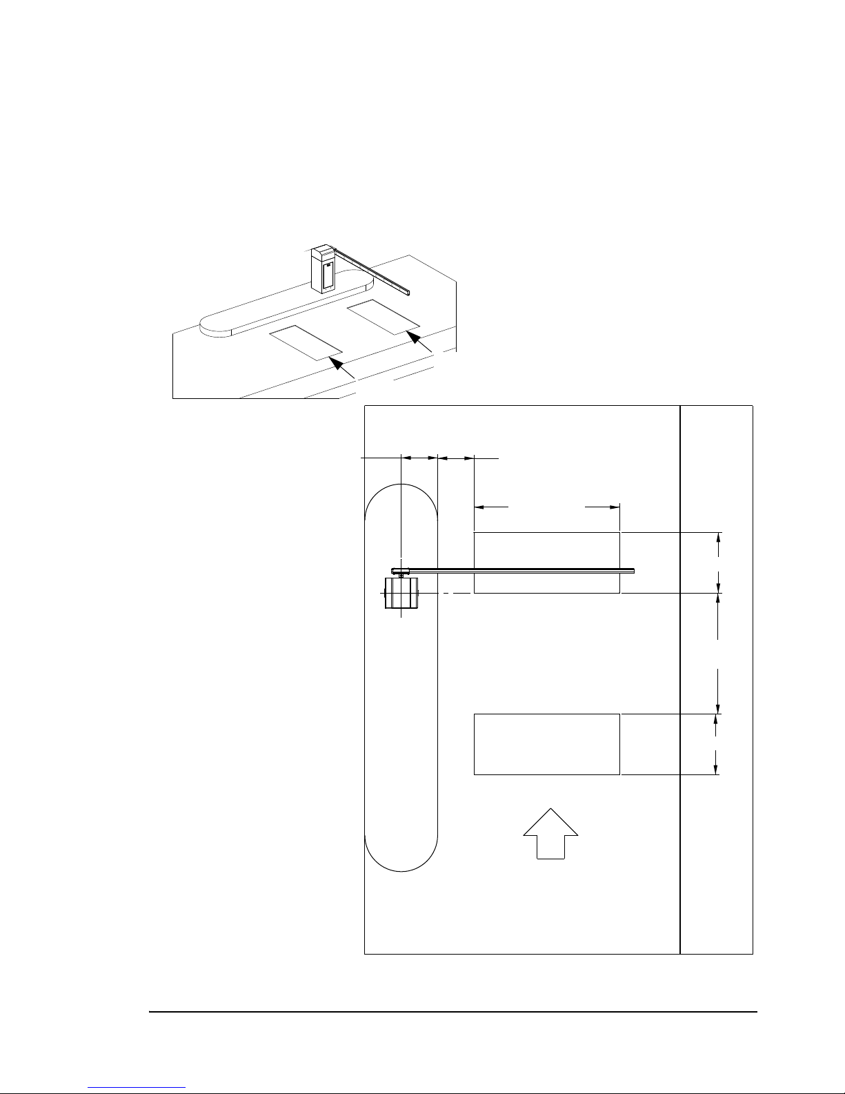
Free mode is used in a single-direction lane through which a patron enters or exits the
facility free of charge. This mode requires two vehicle detector loop inputs: loop A and
loop B. When a vehicle pulls onto the loop A, the gate arm raises. The gate arm lowers
after the vehicle clears loop B.
Figure 1.1
Free Gate with Opening Loop
PosiDRIVE Security Gate ZMA-330, Ver. 6 PosiDRIVE Security Gate Operational Overview • 3
Page 12
Pay Mode
TRAFFIC FLOW
2'-6" (.76 m)
8'-3" (2.5 m)
2'-6" (7.6 m)
1'-6" (.46 m)
6' (1.8 m)
9'-6" (2.9 m)
1'-6"
(.46 m)
A
B
Loop B
Loop A (optional)
Vend Device
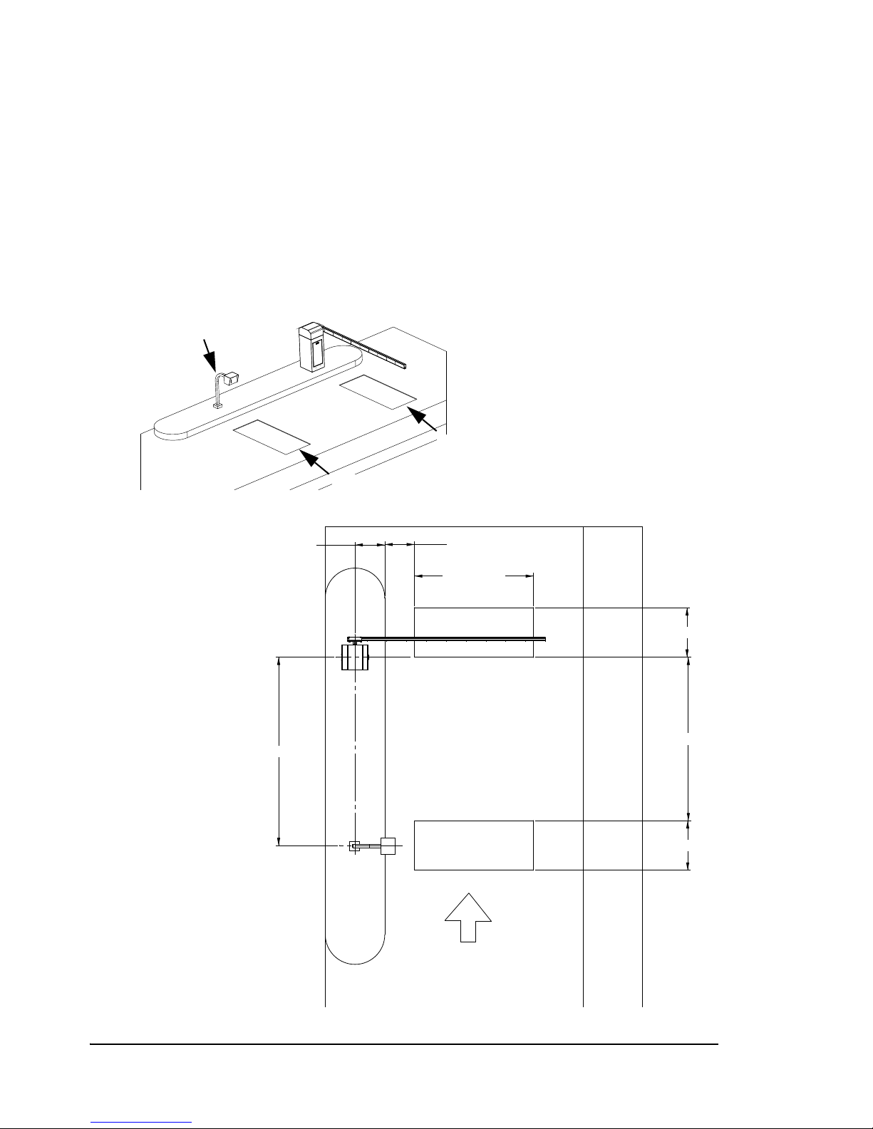
Pay mode is used in a single-direction lane in which controlled access is required to
enter or exit the facility. This mode requires a vehicle detection loop (loop B) and a
vend-device such as a card reader or a switch that a booth attendant uses to raise the
gate. The gate arm lowers after the vehicle clears loop B.
Note: An additional loop (loop A) may be used to enable the vend device, for
example, the lane may contain a ticket issuing device that is activated when the
patron pulls onto loop A.
Figure 1.2
Pay Gate
4 • PosiDRIVE Security Gate Operational Overview ZMA-330, Ver.6 PosiDRIVE Security Gate
Page 13
Pay/Free Mode
TRAFFIC FLOW INTRAFFIC FLOW IN
TRAFFIC FLOW OUTTRAFFIC FLOW OUT
2'-6"2'-6" (.76 m)(.76 m)
5'5' (1.5 m)(1.5 m)
2'-6"2'-6" (.76 m)(.76 m)
1'-6"1'-6" (.46 m)(.46 m)
6'6' (1.8 m)(1.8 m)
9'-6" (2.9 m)9'-6" (2.9 m)
1'-6"1'-6" (.46 m)(.46 m)
1'-6"1'-6" (.46 m)(.46 m)
A
B
Loop A
Loop B
Vend Device
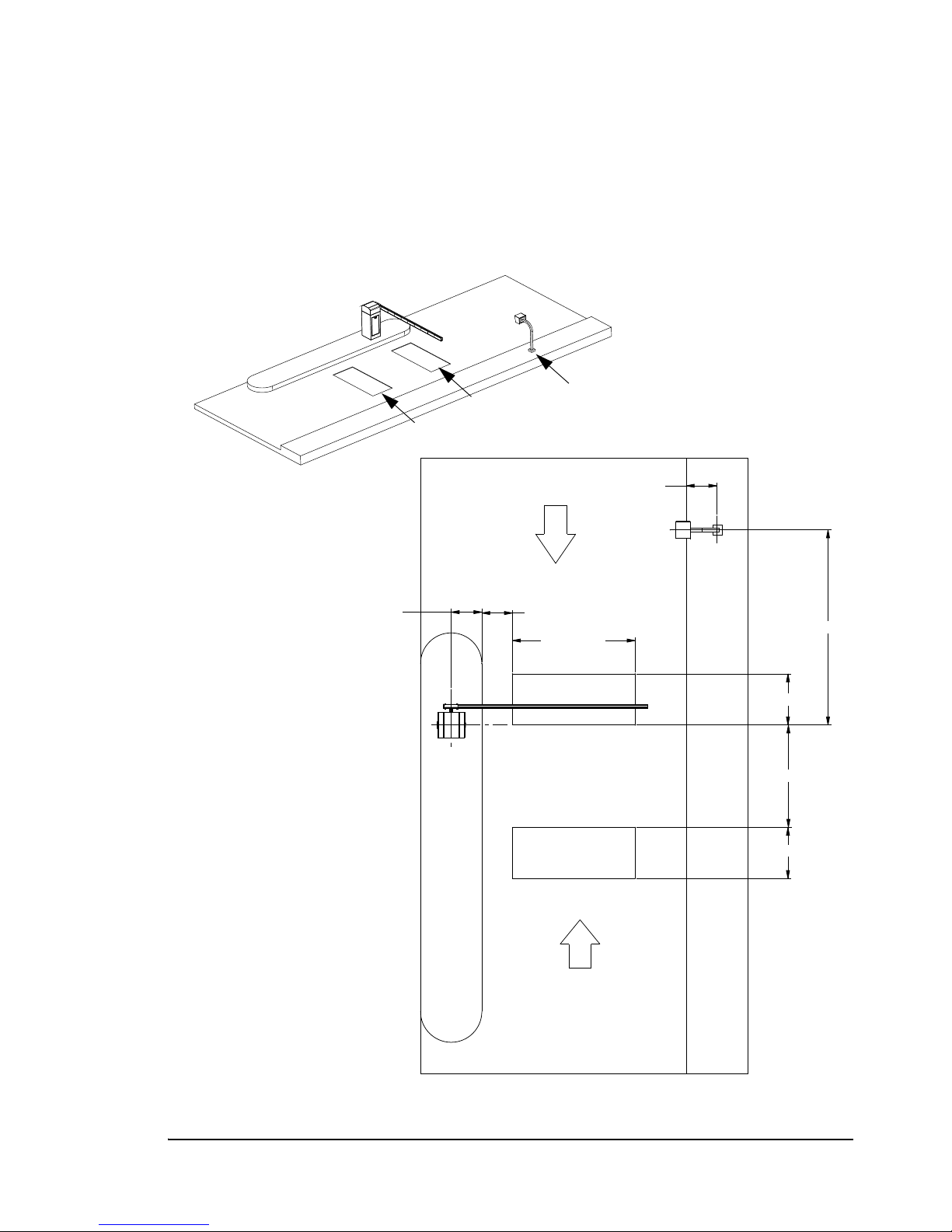
Pay/free mode is used in a dual-direction lane. It requires two vehicle detection loops
(loop A and loop B) and a vend-device such as a card reader. In the free direction,
vehicle presence on loop A vends the gate. In the pay direction, the vend-device vends
the gate. In either direction, the gate arm lowers after the vehicle clears the loop B.
Figure 1.3
Pay/Free Gate
PosiDRIVE Security Gate ZMA-330, Ver. 6 PosiDRIVE Security Gate Operational Overview • 5
Page 14

Power Failure Detection
The PosiDRIVE controller is able to sense when there is a power failure. If the
controller is programmed to raise the gate arm during a power failure, the controller uses
the power from backup battery assembly to raise the gate arm automatically. The gate
arm stays in the up position until the power is restored.
Note: If the controller is not programmed to automatically raise the gate, the gate must
be raised manually. See “Locking, Unlocking, and Advancing the Gate Arm” on
page 49.
PosiDRIVE Structural Overview
This section describes the following PosiDRIVE components:
■ “Gate Enclosure (Cabinet)” on page 6
■ “Mechanical Components” on page 7
■ “Drive Mechanism” on page 10
■ “Electrical Components” on page 10
■ “Gate Arm” on page 13
■ “PosiDRIVE Controller” on page 14
Gate Enclosure (Cabinet)
Federal APD, Inc. builds the PosiDRIVE gate enclosure using 0.090 inch galvanized
steel. The enclosure is weather resistant and allows proper operation in all weather
conditions and temperatures ranging from -30°F (-34°C) to 140°F (60°C). Louvres on
the back and cutouts on the four bottom corners of the enclosure provide air circulation,
thus preventing excessive moisture buildup.
The enclosure is 15 inches W x 16 inches D x 42 inches H (38 cm W x 41 cm D x 107
cm H), finished in yellow or white powder coat paint. The enclosure consists of two
pieces, a base and a removable cap. The base houses the power supply and electronics
package as well as provides the main structure of the enclosure. In addition, the base
provides reinforced flanges for installation, hookup points for the mainsprings, and
mounting provisions for the drive mechanism. Figure 1.4 illustrates the main
components of the gate enclosure.
The enclosure cap is a removable piece that provides easy access to the drive
mechanism without disrupting the operation of the gate. Inspection and maintenance can
be performed easily by removing the enclosure cap. It is secured by four draw latches to
the base, requiring no tools to remove or install. See “Removing the Enclosure Cap” on
page 16.
6 • PosiDRIVE Structural Overview ZMA-330, Ver.6 PosiDRIVE Security Gate
Page 15
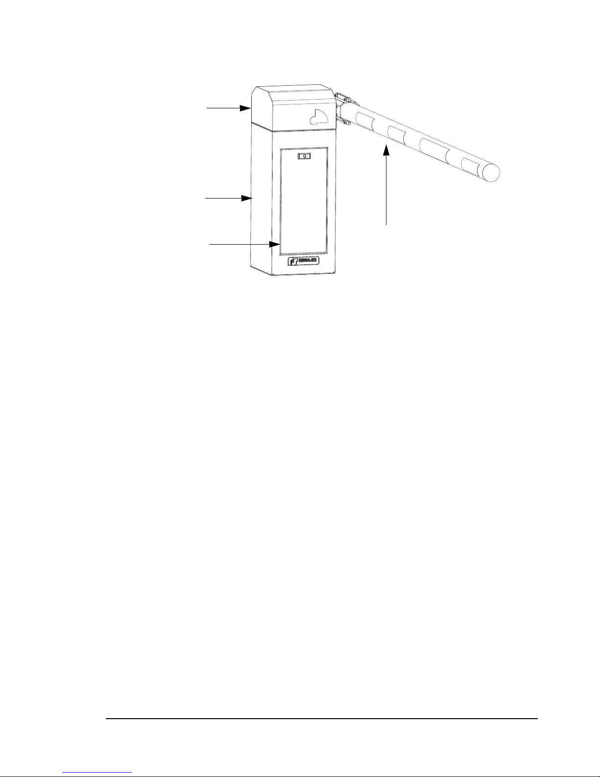
Figure 1.4 Enclosure Components
Enclosure Cap
Enclosure Base
Enclosure Door
Gate Arm
Mechanical Components
The PosiDRIVE gate is powered by a 150 watt, 24 VDC brushless DC gear motor.
The motor is connected directly to a fully sinusoidal four-bar drive mechanism. A
sinusoidal mechanism has the distinct advantage of providing smooth, progressive
acceleration and a mechanical advantage at the limits of travel, where it is needed most.
This arrangement eliminates the need for Vee-belts and their associated maintenance.
One advantage of a brushless DC motor is that the gate can adjust the speed of the entire
system depending on the size of the arm installed. Therefore, the same motor and
gearbox can be used in all situations, allowing the flexibility of using any size gate arm.
Another advantage to the brushless DC motor is the ability of the gate to know where
the gate arm is at all times. The motor provides an output that is monitored by the
controller. The controller interprets the signals to determine arm position and speed.
Using this information, the PosiDRIVE gate operates like a full servo system, providing
benefits such as not requiring mechanical contact to limit its travel, no limit switches,
and an extremely sensitive collision detect system.
The PosiDRIVE gate uses as many as four internal extension mainsprings to
counterbalance the weight of the gate arm. The number of mainsprings and their
adjustment must be properly set at the time of installation in order for the gate to
function properly. When correctly set, these mainsprings offset the torque on the
mechanism created by the weight of the arm, providing a safe, balanced system which
greatly reduces the power required by the motor and increases the efficiency of the gate.
Figure 1.5, on page 8 shows the PosiDRIVE mechanical components. Component
descriptions follow the illustration.
PosiDRIVE Security Gate ZMA-330, Ver. 6 PosiDRIVE Structural Overview • 7
Page 16
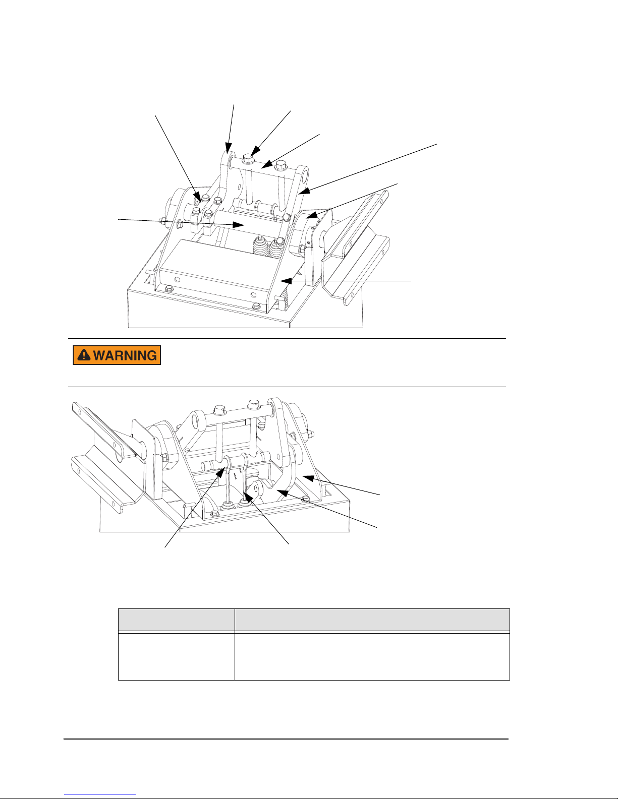
Mainshaft Crank
Part 1
Mainspring Adjustment Bolt
Mainspring Pivot Bar
Mainspring Crank
Mainshaft Bearing
Mainshaft
Mechanism Frame
Mainshaft Crank
Part 2
Connecting Rod
Motor Crank
Mainspring
Mainspring Connection Bar
To prevent a serious pinching injury including dismemberment, use
care when working with the drive mechanism and alway terminate
power prior to performing maintenance or repairs.
Figure 1.5 Mechanical Components
Table 1.1
Mechanical Component Descriptions
Component Description
Mechanism Frame Steel frame that forms the foundation for the PosiDRIVE
mechanism. All of the drive components, including the
motor and mainshaft are attached to the mechanism frame.
8 • PosiDRIVE Structural Overview ZMA-330, Ver.6 PosiDRIVE Security Gate
Page 17
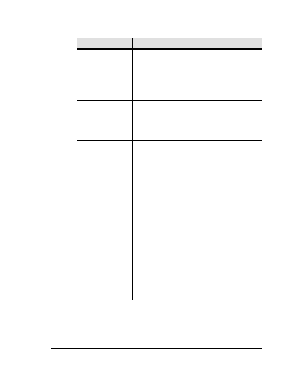
Table 1.1 Mechanical Component Descriptions (Continued)
Component Description
Motor 24 VDC gear motor that powers the PosiDRIVE gate. The
motor and gear box are contained in a single sealed
housing for simplicity and maintenance-free operation.
Motor Crank Link that is attached to the output shaft of the motor. This
link is attached to the motor shaft by means of a friction
clamp but also includes a keyed shaft to prevent slipping
under all conditions.
Connecting Rod Intermediate link in the PosiDRIVE system. The connecting
rod incorporates two high quality spherical bearings for
maximum life and excellent tolerance to misalignment.
Mainshaft Crank Part 1 One of two combined pieces that attach to the mainshaft
and provide the driving force to the mainshaft.
Mainshaft Crank Part 2 The second of the main driving links. This piece is also
designed to serve as an attachment point for the spring
system. It incorporates a single high quality deep groove
ball bearing that one end of the mainspring pivot bar rests
in.
Mainspring Crank Other link attached to the mainshaft that serves as the
second attachment point for the spring system.
Mainspring Pivot Bar Bar that rides in the pair of ball bearings in the mainshaft. It
links and supports the mainspring adjustment bolts.
Mainspring
Connection Bar
Bar to which the mainsprings are attached. The connection
bar incorporates four shallow grooves to keep the
mainsprings properly positioned.
Mainspring
Adjustment Bolts
The two long bolts that connect the mainspring connection
bar to the mainspring pivot bar. They provide the means to
fine-tune the spring tension to a given arm.
Mainshaft Shaft that carries the gate arm at one end and to which the
driving links are attached.
Mainshaft Bearings Large bearings mounted to the sides of the mechanism
frame that carry the mainshaft.
Gate Arm Flange Arm carrier that is attached to the end of the mainshaft.
PosiDRIVE Security Gate ZMA-330, Ver. 6 PosiDRIVE Structural Overview • 9
Page 18

Drive Mechanism
The drive mechanism in the PosiDRIVE gate is a direct drive, sinusoidal mechanism.
This system provides a substantial mechanical advantage for the motor at the beginning
and ending of a cycle when it is most needed. The result of this is that when the gate is at
the extreme limits of travel, in the “full down” or “full up” position, the mechanism is
“locked” and cannot be manually advanced by pushing the gate arm. In other words, at
the full up and full down positions, the mechanism cannot be driven or advanced by any
torque applied to the mainshaft. When servicing the PosiDRIVE gate, you must be
aware of this.
There are times, such as when setting the mainsprings, when you must operate the
mechanism by hand, using the gate arm. It is also necessary at times during this
procedure and others to ensure that the linkage is in the fully locked up position for
safety. Raising the gate arm by hand will NOT bring the linkage into this position. It will
bring it closed, but it will not be fully locked.
In order to lock the mechanism, you must always advance the mechanism by hand for
the last few degrees of travel. That is, if you raise or lower the arm by hand to what feels
like the limits of its travel, the mechanism still must be manually advanced a small
amount to ensure that it is in the locked position. If the mechanism is already locked,
either up or down, then it becomes impossible to get it out of this position by moving the
gate arm. The mechanism must be manually advanced out of the locked position before
moving the gate arm. This is a side effect of the sinusoidal linkage and the variable
mechanical advantage the system provides.
For instructions on manually advancing the mechanism into and out of the locked
positions, see “Locking, Unlocking, and Advancing the Gate Arm” on page 49.
Electrical Components
The use of a 24 VDC motor in the PosiDRIVE gate provides several electrical benefits.
First, by using a low (non-hazardous) voltage throughout the system, the risk of shock to
service personnel is greatly reduced. The PosiDRIVE gate utilizes a universal input 24
volt power supply. This supply can accept input voltages anywhere from 85 VAC to 264
VAC at 50 or 60 Hz. This allows the PosiDRIVE gate to be installed into virtually any
voltage environment without modification, providing maximum flexibility. The
nameplate rating for power consumption is 2 amps for 115 VAC and 1 amp for 220
VA C .
The PosiDRIVE gate is also equipped with a backup battery assembly, which provides
power to the controller and motor in the event of a power failure to allow the
PosiDRIVE gate to raise the arm. It is not intended to operate the gate in a power failure
mode, but just to provide the option of raising the gate to allow patrons to exit. It also
does not power any loop circuits. Automatically raising the gate during a power failure
is a configurable option. See “Setting the DIP Switches” on page 42.
10 • PosiDRIVE Structural Overview ZMA-330, Ver.6 PosiDRIVE Security Gate
Page 19
The PosiDRIVE gate can detect a line power failure and will wait (operating on battery
Safety Switch
PosiDRIVE Controller
Power Supply
Motor Driver
Board
Manual/Auto Switch
Circuit Breaker/Master
Power Switch
Junction Box
Electical Subpanel
power) for a period of 10 seconds before raising the arm. This eliminates false responses
to transient (short term) power glitches. On detection of the return of line power, again a
delay of 10 seconds is provided before normal operation is resumed. The backup battery
assembly has ample power to provide this feature for several years before replacement.
The door safety switch disconnects power to the motor under ALL
circumstances. If the door safety switch is bypassed (not normally
recommended) and the circuit breaker switch is turned off for any
reason, after 10 seconds, the gate activates under battery power and
raises the arm. The powerful drive mechanism can cause serious
bodily injury. Do not bypass the door safety switch unless absolutely
necessary.
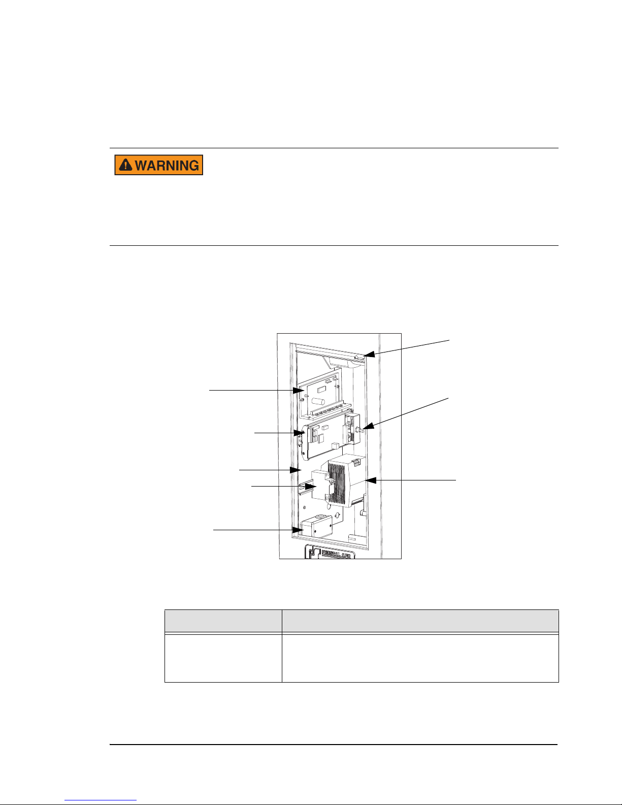
Figure 1.6, on page 11 shows the PosiDRIVE gate electrical components. Component
descriptions follow the illustration.
Figure 1.6
Electrical Components
Table 1.2 PosiDRIVE Electrical Component Descriptions
Component Description
Junction Box A junction is located on the electrical sub-panel below the
PosiDRIVE Security Gate ZMA-330, Ver. 6 PosiDRIVE Structural Overview • 11
circuit breaker, where an installer can mount a convenience
outlet.
Page 20
Table 1.2 PosiDRIVE Electrical Component Descriptions (Continued)
To avoid serious injury, use
extreme caution when
bypassing the safety switch.
Make sure all technicians are
clear of the drive mechanism
and the gate arm path before
bypassing the switch.
Component Description
Circuit Breaker Switch This is the main overload protection mechanism for the
entire gate. It is also the master power switch. CAUTION:
The door safety switch disconnects power to the motor
under ALL circumstances. If the door safety switch is
bypassed (not normally recommended) and the breaker
switch is turned off for any reason, the system will respond
to this as a line power failure. After 10 seconds, the gate will
activate under battery power and raise the arm. Use
extreme caution when servicing the gate and be aware of
this condition. This is why the door safety switch should not
be bypassed unless absolutely necessary.
Electrical Sub-Panel Steel panel mounted inside the enclosure, which holds all of
the electrical components.
PosiDRIVE Controller “Brain” behind the PosiDRIVE gate and its operation. It is a
plug-in, microprocessor-based controller that monitors and
directs all operations of the gate. It is capable of operating
on input voltages ranging from 18 VDC to 32 VDC.
Motor Driver Board “Brain” behind the brushless DC motor. It controls the
proper operation of the motor as well as regulates the power
delivered to the motor.
Safety Switch A plunger-style switch that automatically terminates power
to the motor when the enclosure door is open. To bypass
the switch, pull out the plunger. To reactivate the switch,
depress the plunger. The plunger springs back to the safe
position.
Manual/Auto Switch Setting the switch to the Manual position raises the arm to
the up position indefinitely. Setting the switch to the
Automatic position causes the gate to resume normal
operation.
12 • PosiDRIVE Structural Overview ZMA-330, Ver.6 PosiDRIVE Security Gate
Page 21
Component Description
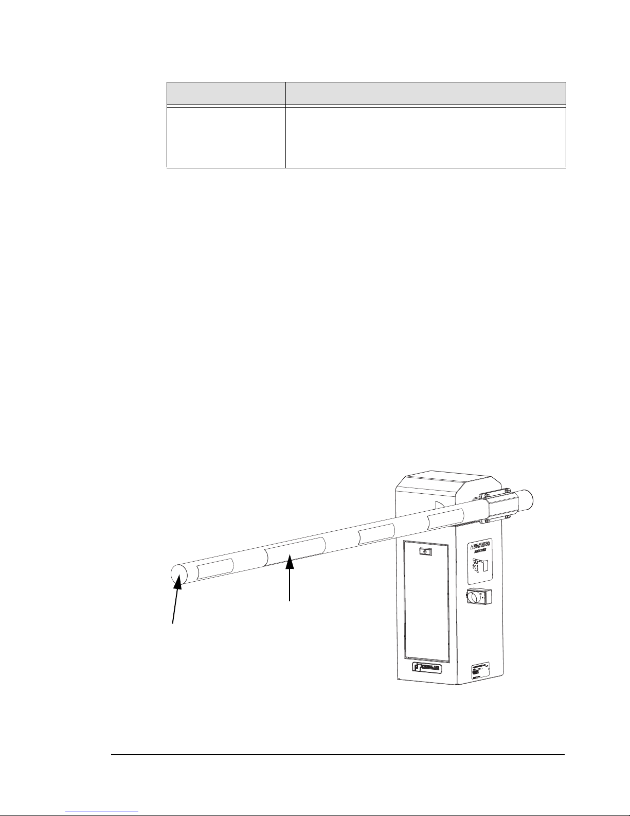
Gate Arm
End Cap
Power Supply Unit that provides the 24 VDC power required by all
Gate Arm
The size of the standard PosiDRIVE gate arm (Figure 1.7, on page 13) ranges from 10 to
20 feet (3.05 m to 6 m) in length and is constructed of extruded aluminum. It is finished
with white powder coat paint with reflective striping. The gate arm is 4 inches (100mm)
in diameter and extends from the gate cabinet at a height of approximately 36 inches (91
cms) from the mounting surface.
The standard gate arm is hollow and has molded plastic pieces that attach at the ends of
the gate arm to prevent snow, ice, or debris from building up inside the gate arm. It is
internally counterbalanced with two, three, or four adjustable extension mainsprings,
depending on the length of the arm. The mainsprings balance the weight of the gate arm,
reducing the power requirement by the motor. See “Setting the Mainsprings” on
page 38.
Table 1.2 PosiDRIVE Electrical Component Descriptions (Continued)
components of the PosiDRIVE gate. The PosiDRIVE power
supply can accept input voltages ranging from 85 VAC to
264 VAC at 50 or 60 Hz.
The PosiDRIVE gate can also support a folding gate arm (Figure 1.8, on page 14) for
locations that have restricted overhead clearance. The standard folding gate arm is 10 ft.
(3.05 m) in length and is constructed of clear white pine. It is finished in diagonal stripes
of black and white enamel.
Figure 1.7
Standard Gate Arm
PosiDRIVE Security Gate ZMA-330, Ver. 6 PosiDRIVE Structural Overview • 13
Page 22
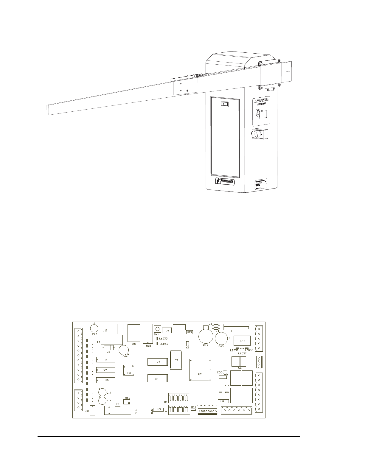
PosiDRIVE Controller
Figure 1.8 Folding Gate Arm
The PosiDRIVE Controller houses one DIP switch bank, which is marked “SW2” on the
board. The PosiDRIVE Controller also houses the Reset switch (SW1) and connectors
for several gate functions, including:
■ The motor controller plugs into connector JP4.
■ The Power Supply wires into J1.
■ The Manual/Auto switch is connected into connector J1.
■ Field Wiring connections are made into connector JS1.
Note: Connectors JP1 and JP2 are for Federal APD use only.
Figure 1.9
11
10
PWR
ON
9
LOOP A
8
LOOP B
7
6
VEND
5
RAISE
4
UP LMT
3
DWN LMT
2
SPARE
1
PWR FL
JS1
AUX1
AUX2
AUX3
AUX4
JS4
PosiDRIVE Controller
9
10
JP2
SW2
JP1
SW3
1
2
TORQ LMT
DIRECT
ENABLE
87654321
JP4
BRAKE
RLY3
RLY4
TACH
JP6
1
RLY2
RLY1
65
JP5
K4
K2
432
JS2
10
J4
1
2
3
4
5
JP3
1
2
3
K3
4
5
6
7
K1
8
1
J1
14 • PosiDRIVE Structural Overview ZMA-330, Ver.6 PosiDRIVE Security Gate
Page 23

DIP Switches
The SW2 DIP switches (Figure 1.9, on page 14) control the following functions:
■ Vend Counts—DIP switch 1 is used to enable or disable vend counts. If switch 1 is
open, vend counts are disabled; if switch 1 is closed, vend counts are enabled.
■ Backout Gate Reset Time—DIP switches 3 and 4 are used to set the time, from 15
seconds to 60 seconds, that the gate arm stays up until a vehicle passes through the
gate.
■ Gate Length—DIP switches 5 and 6 are used to program the controller for the
length of the gate arm.
■ Backout Gate Arm Timeout—DIP switch 7 is used to indicate whether the gate
arm remains raised for a specified period of time (determined by setting the Backout
Gate Reset Time using DIP switches 3 and 4) or remains raised until the reset loop
(B) is cleared.
■ Power Fail Raise—DIP switch 8 is used to set the gate’s behavior when a power
failure occurs.
Note: For DIP switch setting instructions, see “Setting the DIP Switches” on page 42.
Also note, DIP switch 2 is unused.
Inputs
The PosiDRIVE Controller (Figure 1.9, on page 14) has the following inputs to support
gate operation:
■ Loop A (connector JS1-2). Input from an external vehicle detector indicating a
presence on the A Loop.
■ Loop B (connector JS1-3). Input from an external vehicle detector indicating a
presence on the B Loop.
■ Vend (connector JS1-4). Input from an external device signalling the gate to vend.
■ Raise/Lower (connector JS1-5). Input from an external device signalling the gate to
raise. This would be used with an external operator switch, which when enabled,
raises the gate.
PosiDRIVE Security Gate ZMA-330, Ver. 6 PosiDRIVE Structural Overview • 15
Page 24

Outputs
The PosiDRIVE Controller (Figure 1.9, on page 14) has the following external outputs:
■ Gate Up field output (connector JS2, 1 and 2). When the gate is down, outputs 1 and
2 are open. When the gate starts to travel upward, outputs 1 and 2 close (are
connected) until the gate starts to travel downward again.
■ System Fault relay output (connector JS2, 3 and 4). When there is a system fault,
outputs 3 and 4 are closed (connected). In a normal condition, outputs 3 and 4 are
open.
Opening the Enclosure Door
Gate installation, maintenance, and repair typically call for opening the gate enclosure to
access the gate’s electrical components.
The enclosure door, which has a single T-handle lock, can be easily removed by
unlocking the handle and lifting the door up and out. The door must be removed before
the enclosure cap can be unlatched and removed.
As the door is removed, the safety switch inside the door frame pops out to disconnect
power to the gate motor, ensuring that the drive mechanism does not actuate while gate
is open. This safety precaution is designed to prevent serious bodily injury.
If your hands are in the path of the gate mechanism and the
mechanism actuates, a severe injury, including dismemberment, can
occur.
If it is absolutely necessary to operate the gate with the cover removed, bypass the
switch by pulling the plunger out.
To reactivate the switch, depress the plunger fully.
Removing the Enclosure Cap
Gate installation, maintenance, and repair typically call for removing the gate enclosure
cap to access the gate’s drive mechanism.
16 • Opening the Enclosure Door ZMA-330, Ver.6 PosiDRIVE Security Gate
Page 25
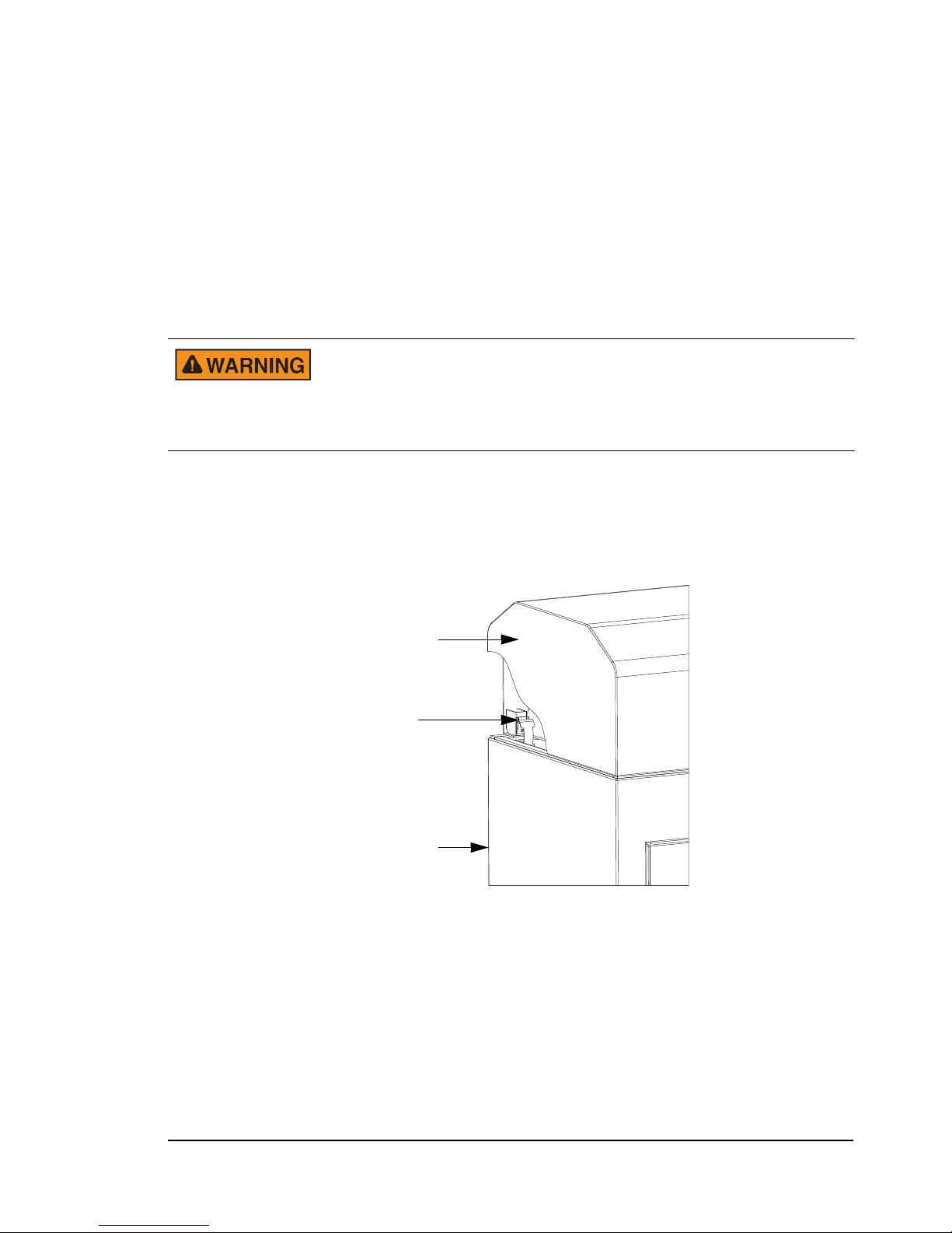
To remove the enclosure cap, follow these steps:
Enclosure Cap
Draw Latch
Enclosure Base
1. Remove the enclosure door by unlocking the handle and lifting the door up and out.
Note the safety switch inside the door frame. As the door is removed, this switch
disconnects power to the gate motor under all circumstances, allowing you to safely
reach up under the cap to unlatch it and service the gate. If it is necessary to operate
the gate with the cover removed, the switch may be bypassed by pulling the plunger
out to the bypass position. The switch can be reactivated by depressing the plunger.
It then acts as a safety switch again, preventing motor activity until the door is
replaced.
Use extreme caution if operating the gate with the door and/or
enclosure cap removed. This is a powerful mechanism that can cause
serious injury if not handled properly. It is strongly recommended that
the cap be in position and latched and the door be installed when the
gate is in operation.
2. One draw latch, which holds the cap in place, is located on each inside top corner of
the enclosure base. Reach inside the enclosure and unhook all four latches.
Figure 1.10
Draw Latch
3. Lift the cap straight up and off. Use care when removing or replacing the cap so as
not to damage any of the weather-stripping.
4. To replace the cap, lower the cap straight down on to the base, again using caution
with the weather-stripping. Reach inside the enclosure and re-hook the draw latches.
PosiDRIVE Security Gate ZMA-330, Ver. 6 Removing the Enclosure Cap • 17
Page 26

18 • Removing the Enclosure Cap ZMA-330, Ver.6 PosiDRIVE Security Gate
Page 27

CHAPTER 2
Installation
This chapter contains the following topics:
Installation Overview ........................................................................................20
Installing the Enclosure .....................................................................................20
Wiring the Gate .................................................................................................23
Installing the Gate Arm .....................................................................................25
Install a Standard Gate Arm........................................................................26
Install a Folding Gate Arm .........................................................................27
Change the Gate Arm Configuration ..........................................................34
Setting the Mainsprings.....................................................................................38
Disabling the Locked-Down Feature (Optional)...............................................40
Setting the DIP Switches...................................................................................42
PosiDRIVE Security Gate ZMA-330, Ver. 6 Installation • 19
Page 28
Installation Overview
The installation procedures described in this section are broken into the following tasks:
1. “Installing the Enclosure” on page 20
2. “Wiring the Gate” on page 23
3. “Installing the Gate Arm” on page 25
4. “Setting the Mainsprings” on page 38
5. “Disabling the Locked-Down Feature (Optional)” on page 40
6. “Setting the DIP Switches” on page 42
Moving parts can cause serious bodily injury, and hazardous voltage
can shock, burn, or cause death. Turn off the power to the gate and
disconnect the battery before performing any maintenance or repairs.
Installing the Enclosure
This section explains how to install the PosiDRIVE Security Gate enclosure.
Note: The base flange of the PosiDRIVE includes a series of holes designed to support
retrofitting the PosiDRIVE gate into a previous Federal APD gate installation,
such as the G-89, CG-90, G-90, or 500 Industrial Gate. It may be possible to use
as many as three of the existing mounting bolts. Because the base of the
PosiDRIVE is deeper than the previous gate, it is not possible to use all four
existing bolts. Use three of the existing holes and drill new holes in the front
two mounting holes.
If the PosiDRIVE is being installed into an existing 500 Industrial Gate
installation, you may need to position the gate closer to the curb to
accommodate any existing conduit stub-ups. In this case, drill four fresh
mounting holes.
To install the gate on a concrete curb:
Install the enclosure so that the end portion of the gate arm is more
than 2 feet (62 cm) from any rigid object, such as a wall, when fully
extended in the down position. If the distance is less than 2 feet (62
cm), a person may get trapped between the end of the gate arm and the
rigid object, causing bodily injury to the individual.
1. Carefully remove the unit from the shipping crate without damaging the finish.
Leave the enclosure bolted to the bottom pallet until you are ready for installation.
2. Open the gate enclosure door.
20 • Installation Overview ZMA-330, Ver.6 PosiDRIVE Security Gate
Page 29
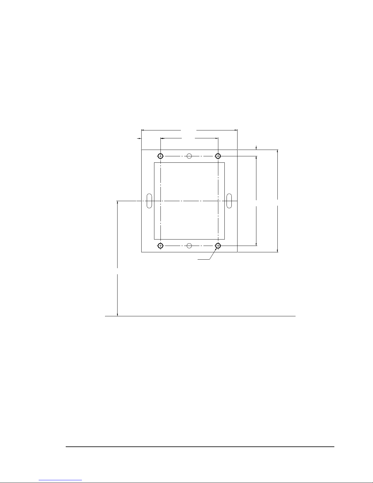
3. Remove the bolts that fasten the cabinet to the bottom pallet.
CURB LINE
16.00
14.00
1.00
15.00
9.00
3.00
18.00
0.75 DIA.
Measurements in
inches
4. Mark the concrete for drilling as follows:
a. Place the cabinet in the installation location, aligned according to the
dimensions provided in Figure 2.1. Make sure that the center line of the cabinet
is 18 inches from the curb line.
b. Use pencil or chalk to mark the concrete through the selected anchoring holes.
Figure 2.1
PosiDRIVE Security Gate Footprint Dimensions
5. Remove the cabinet from the position, and follow the manufacturer’s instructions
for installing the anchor bolts. Redhead #JS-38H, 3/8” x 3” stud anchor, or
equivalent is the recommended anchor bolt.
PosiDRIVE Security Gate ZMA-330, Ver. 6 Installing the Enclosure • 21
Page 30
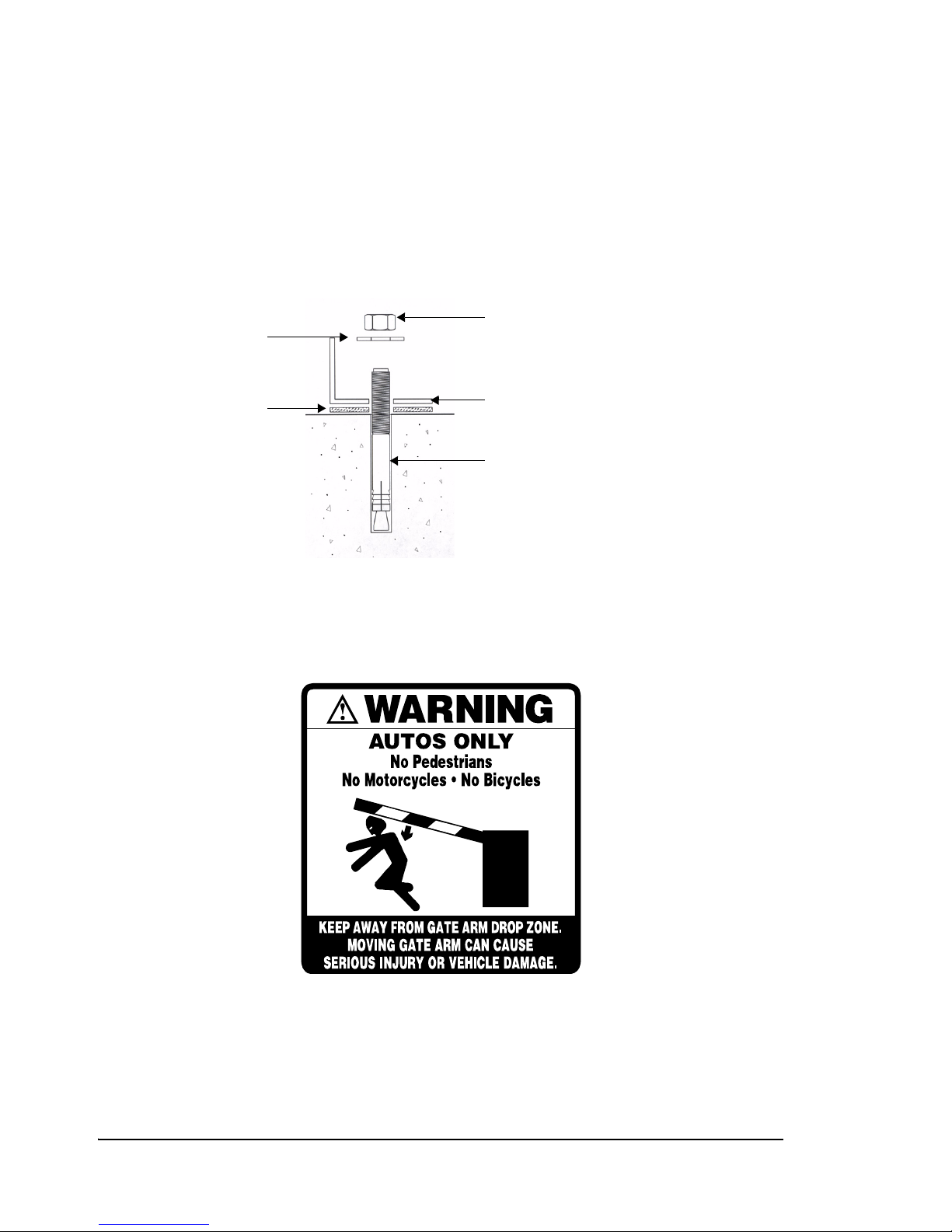
6. Attach the cabinet to the anchor bolts as follows:
Cabinet Base
Anchor Bolt
Washer
Gasket
Nut
a. Place the gaskets over the bolts.
b. Set the cabinet on top of the gaskets, aligning the bolts up through the holes of
the cabinet.
c. Place the washers on the bolts.
d. Screw the nuts onto the bolts, and tighten them to secure the cabinet.
7. Make sure the warning label (Figure 2.2) affixed to either side of the enclosure is
not obstructed by any objects.
Figure 2.2
Gate Cabinet Warning Label (Part # 20-3469)
22 • Installing the Enclosure ZMA-330, Ver.6 PosiDRIVE Security Gate
Page 31
Wiring the Gate
The PosiDRIVE Security Gate is wired to the incoming power source and to a vend
device, such as a vehicle detector loop, a card reader, and/or a raise/lower switch. The
gate wiring depends upon the devices your site uses. Refer to the engineering drawings
supplied with the gate for wiring diagrams that are specific to your site’s configuration.
Note: If you do not have the engineering drawings, obtain a copy from your
distributor. If you are the distributor, contact Federal APD Customer Support to
obtain a copy of the drawings.
The PosiDRIVE optionally comes with a Federal APD Detector Harness that is used to
interface Federal APD detector loops with the gate. This section provides diagrams for
wiring the gate with or without the Federal APD Detector Harness.
To wire the gate:
To prevent serious bodily injury and damage to the equipment:
• Terminate the incoming AC power before wiring the gate.
• Only a licensed electrician should wire the gate.
1. Connect the incoming AC power feed wires to the pigtail leads inside the junction
box (Figure 1.6, on page 11).
2. Per the engineering drawings included with the gate, connect the resident vend
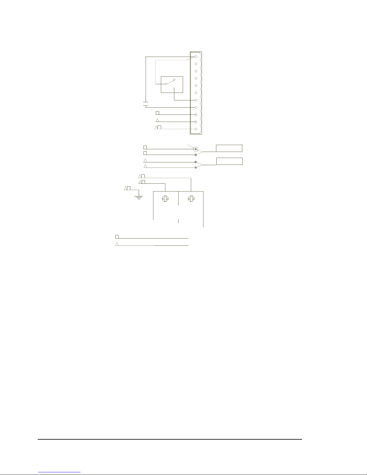
device to the PosiDRIVE Controller. Figure 2.3, on page 24, shows the wiring
schematic when using the Federal APD Detector Harness. Figure 2.4, on page 25
shows the wiring schematic when using a generic detector harness.
PosiDRIVE Security Gate ZMA-330, Ver. 6 Wiring the Gate • 23
Page 32
1
2
3
4
5
6
7
8
9
10
11
VEND DETECTOR HARNESS
RESET DETECTOR HARNESS
VEND
RESET
JS1
NOT USED
NOT USED
NOT USED
NOT USED
INPUT COMMON
C
NO
NC
RAISE/LOWER
SWITCH
N.O. CONTACT
VEND DEVICE
'A' PRESENCE
'B' PRESENCE
VEND
RAISE-LOWER
NOT USED
INPUT COMMON
LOOP
DETECTOR
DETECTOR
LOOP
B
B
F
D
E
D
E
*
*
*
*
*
*
*
SPLICE TYP.
*
*
FAPD DETECTOR HARNESS COLOR CODE:
(REFERENCE DRAWING FCA-10141)
LEGEND:
PIN P/N 11-26498
A
B
C
D
E
F
G
H
I
J
WHITE
BROWN
BLACK
RED
ORANGE
YELLOW
BLUE
GREEN
VIOLET
GRAY
WHITE
RED
BLACK
BROWN
VIOLET
ORANGE
GRAY
GREEN
BLUE
YELLOW
GREEN
BLACK
WHITE
LOAD
LOAD
FAPD PN-21-11929
BREAKER
5 AMP/2 POLE
*
*
*
H
C
A
P/N 12-0128
Figure 2.3 Wiring with the Federal APD Detector Harness
24 • Wiring the Gate ZMA-330, Ver.6 PosiDRIVE Security Gate
Page 33
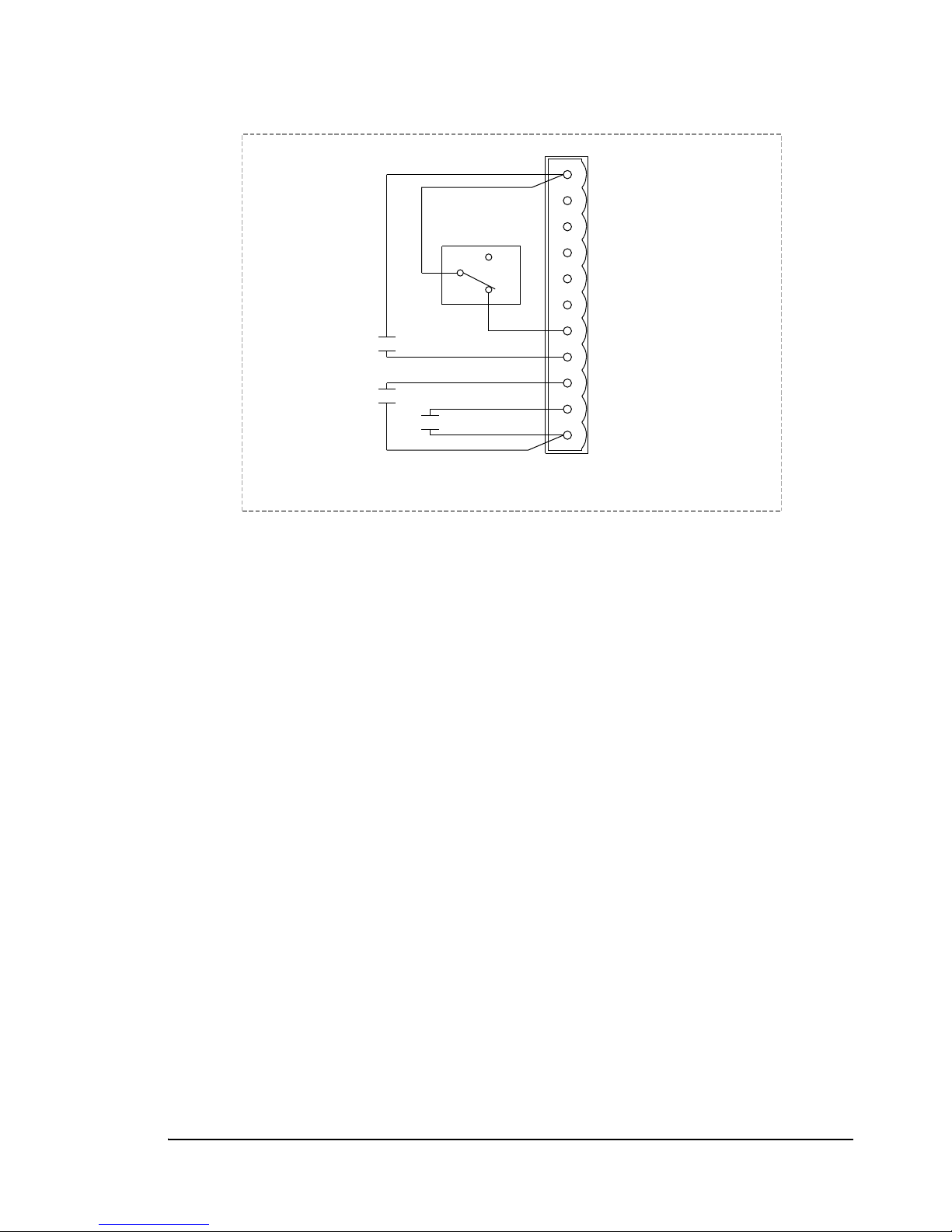
Figure 2.4 Wiring with a Non-Federal APD Detector Harness
JS1
1
10
2
11
9
8
7
6
5
4
3
INPUT COMMON
'A' PRESENCE
'B' PRESENCE
VEND
RAISE-LOWER
NOT USED
NOT USED
NOT USED
NOT USED
NOT USED
INPUT COMMON
C
NO
NC
SWITCH
RAISE/LOWER
VEND DEVICE
N.O. CONTACT
N.O. CONTACT
RESET DET.
N.O. CONTACT
VEND DET.
Installing the Gate Arm
The PosiDRIVE Security Gate supports standard gate arms and folding gate arms for
sites with low overhead clearance. Installation procedures differ depending upon the
type of gate arm you are installing.
The gate is factory configured for left- or right-hand drive based on your site’s
requirement; however, if you receive a gate that is not configured properly for your site,
you can either send the gate back to the factory for re-configuration or you can change
the gate’s configuration yourself.
This section explains how to:
■ “Install a Standard Gate Arm” on page 26
■ “Install a Folding Gate Arm” on page 27
■ “Change the Gate Arm Configuration” on page 34
PosiDRIVE Security Gate ZMA-330, Ver. 6 Installing the Gate Arm • 25
Page 34
Install a Standard Gate Arm
Gate Arm
Mainshaft
Gate Arm Inserts
Arm Clamp
3/8-16 UNC x 1.50”
Hex Bolt
3/8-16 UNC
Hex Nut
3/8” Plain Washer
To install a standard gate arm:
To avoid severe personal injury, place the gate arm mechanism into the
fully up, locked position. See “Locking, Unlocking, and Advancing the
Gate Arm” on page 49.
Additionally, due to the length and weight of the gate arm, two
technicians are required to perform this task.
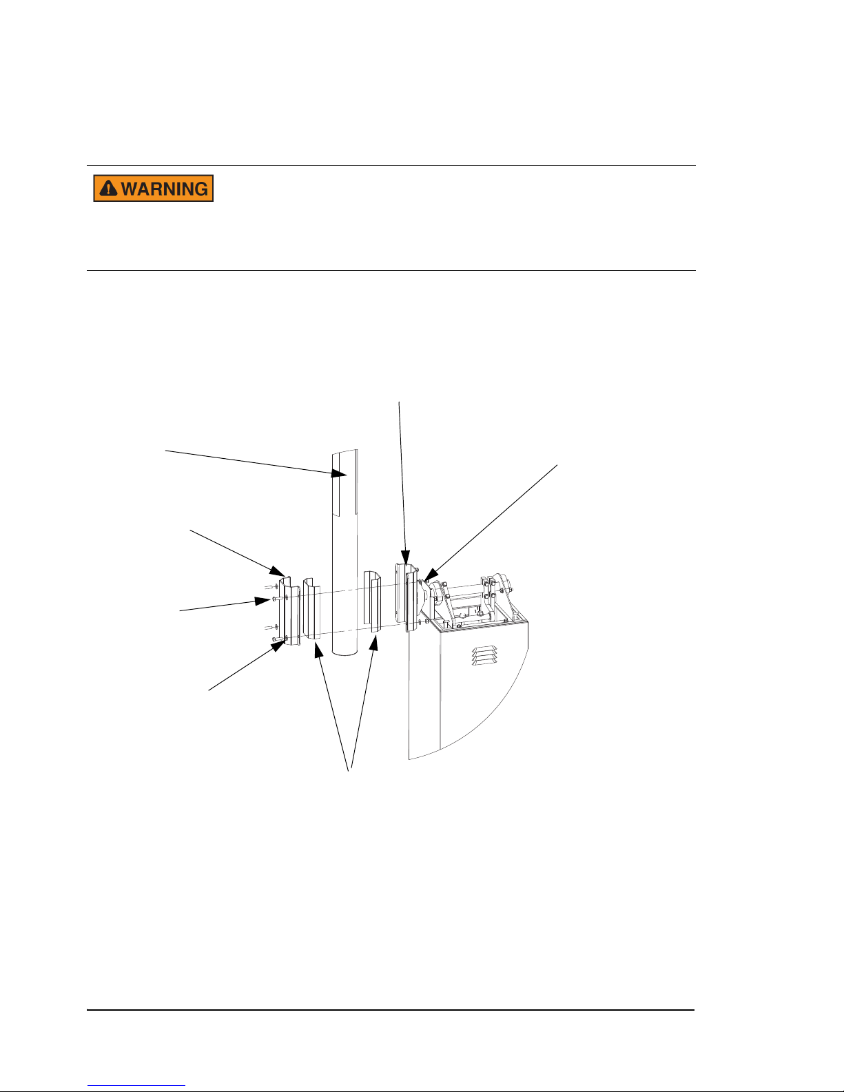
1. Review the following illustration (Figure 2.5) to ensure that you have all of the
required components.
Figure 2.5
Standard Gate Arm Installation
2. Place the gate arm inserts on either side of the gate arm. Position the inserts so that
they are directly underneath the arm clamps.
3. Place the arm into the mainshaft and position the arm clamp over the arm. Make
sure to align the holes in the arm clamp with the holes in the mainshaft.
4. Thread the mounting bolts through the mainshaft and through the arm clamp.
26 • Installing the Gate Arm ZMA-330, Ver.6 PosiDRIVE Security Gate
5. Fit the washers and hex nuts over the bolts and tighten.
Page 35
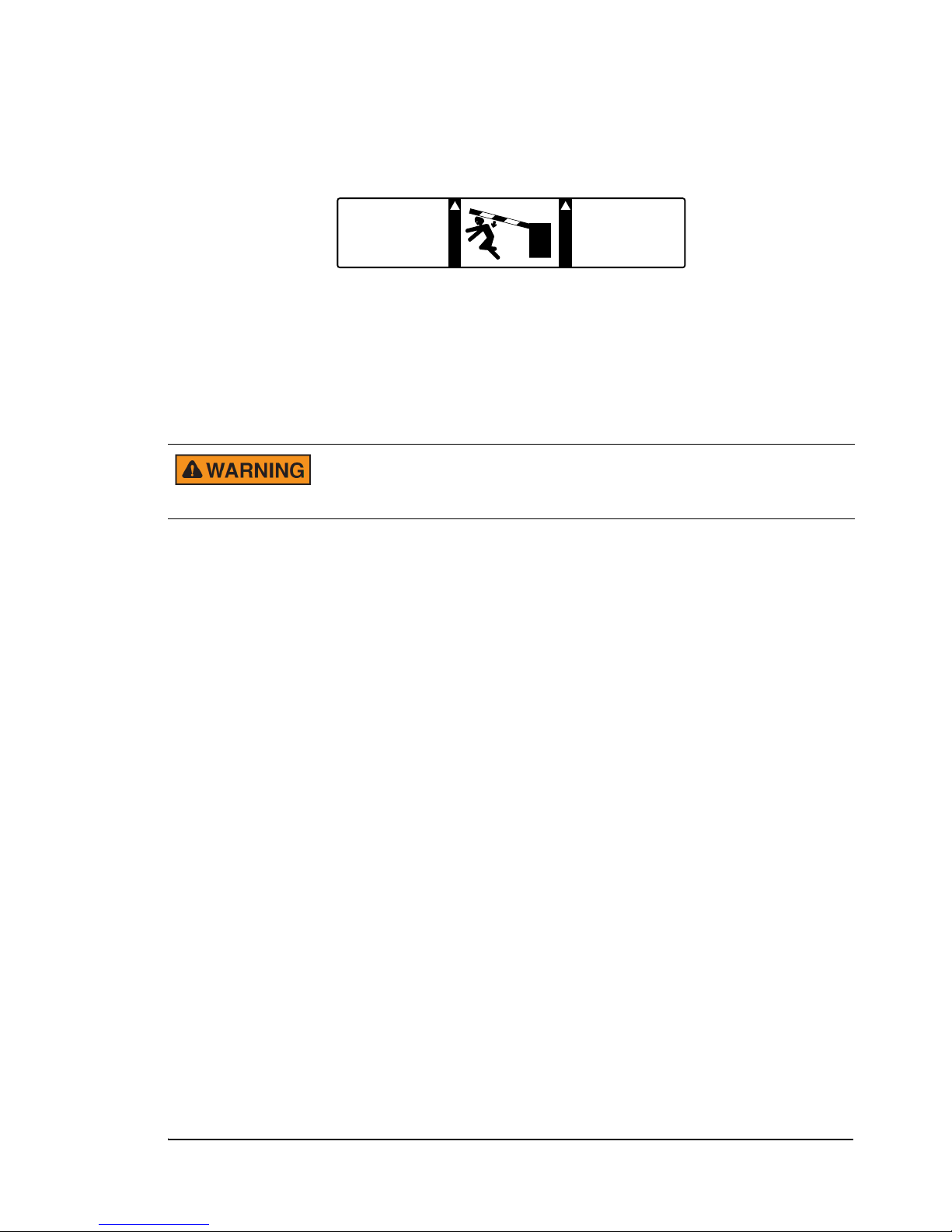
6. Make sure the bright orange warning label, as shown in Figure 2.6, is installed on
!
W
A
R
N
I
N
G
MOVING ARM
CAN CAUSE
BODILY HARM OR
VEHICLE DAMAGE.
W
A
R
N
I
N
G
CARS ONLY:
NO BICYCLES
MOTORCYCLES
OR PEDESTRIANS.
!
both sides of the gate arm.
Figure 2.6
Gate Arm Warning Label (Part # 20-4343)
7. Set the mainsprings. See “Setting the Mainsprings” on page 38.
Install a Folding Gate Arm
Folding gate arms are installed on gates that are located in areas with low overhead
clearance.
To avoid severe personal injury, place the gate arm mechanism into the
full “locked up” position. See “Locking, Unlocking, and Advancing the
Gate Arm” on page 49.
PosiDRIVE Security Gate ZMA-330, Ver. 6 Installing the Gate Arm • 27
Page 36
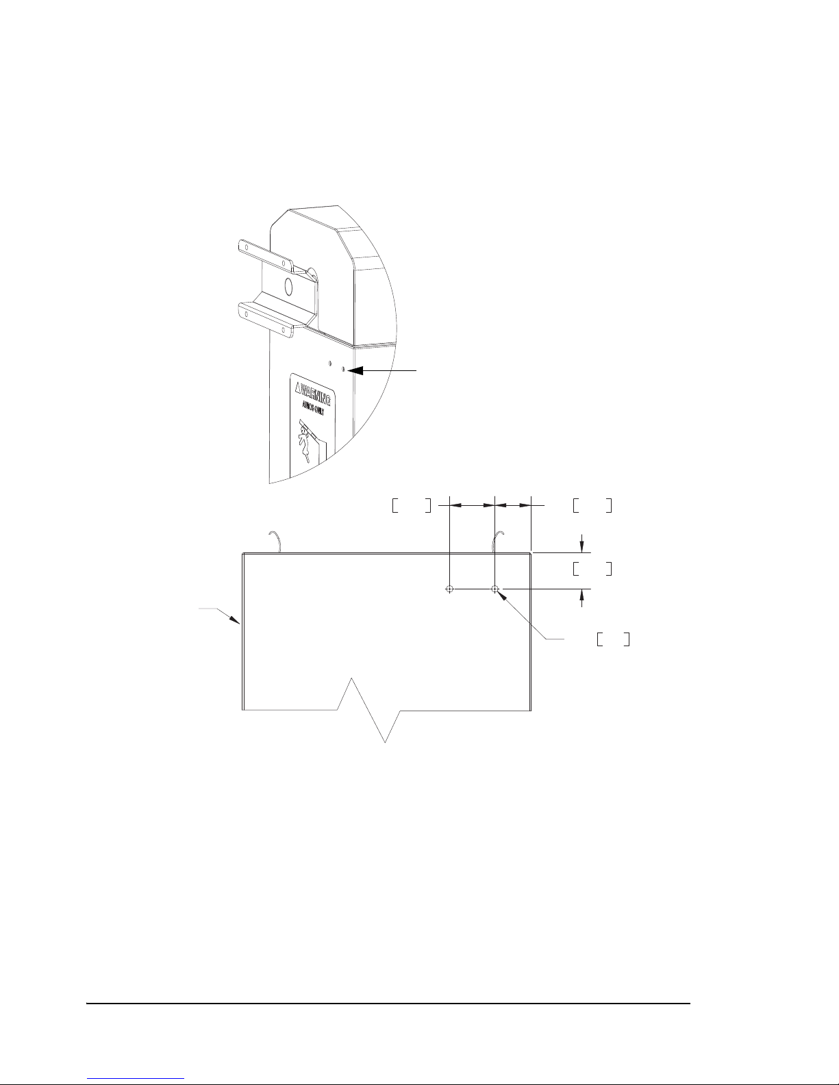
To install a folding gate arm:
Holes for Folding
Gate Arm
1. Drill two 3/8” holes into the side of the gate enclosure. Refer to the dimensions
provided in Figure 2.7.
Figure 2.7
Dimensions for Folding Gate Arm Mounting Hole
2.00 50.802.50 63.50
2.00 50.80
FRONT OF
ENCLOSURE
Ø .38 9.53
2. To inhibit rust, paint the rims of the holes with the PosiDRIVE touch-up paint.
28 • Installing the Gate Arm ZMA-330, Ver.6 PosiDRIVE Security Gate
Page 37
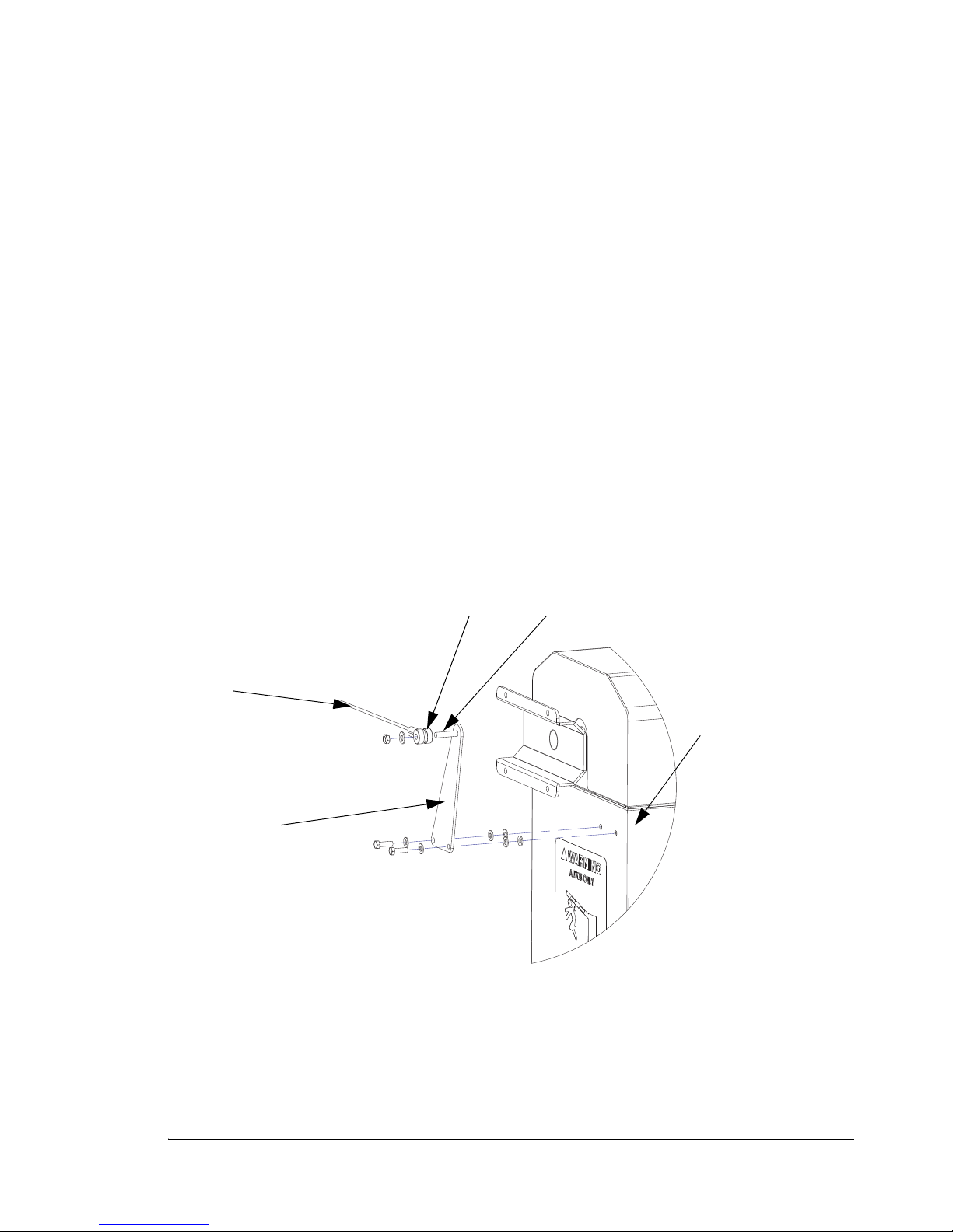
3. Install the cable tower (Figure 2.8) on the side of the gate enclosure using two
Cable Tower
Cable
Spacer Spindle
The two washers and
two nuts on the inside of
the gate are not shown
on this illustration.
5/16-18 x 1” hex bolts, eight 5/16” plain washers, and two 5/16-18 Nylock hex nuts
as follows:
a. Align two washers over each of the holes that you drilled in the gate enclosure.
b. Align the cable tower over the washers.
c. Align one washer over each hole in the cable tower.
d. Thread 1 hex bolt through each hole to fasten the cable tower to the gate
enclosure.
e. On the inside of the gate, place a washer on each bolt and tighten with a Nylock
hex nut.
4. Install the cable on the cable tower (Figure 2.8) using a spacer, cable, one 3/8” plain
washer, and one 3/8-16 Nylock hex nut as follows:
a. Thread the spacer onto the cable tower spindle.
b. Place the washer onto the spindle.
c. Thread the Nylock hex nut onto the spindle and tighten.
Figure 2.8
Installing the Cable Tower
PosiDRIVE Security Gate ZMA-330, Ver. 6 Installing the Gate Arm • 29
Page 38
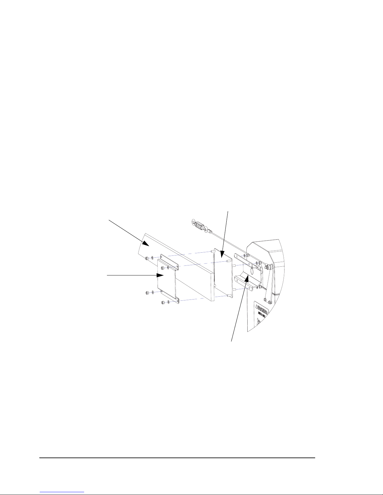
5. Attach the fixed section of the folding gate arm to the gate arm flange (Figure 2.9)
Adapter
(front side)
Retainer
Folding Gate Arm
Fixed Section
Flange
using the adapter, arm retainer, eight 3/8” lock washers, and eight 3/8” Nylock hex
nuts, as follows:
a. Place the studs that are on the back side of the adapter (the side where the studs
are closer together) into the four flange holes and secure the adapter with four
washers and four hex nuts.
b. Place the retainer on the adapter front side studs.
c. Place a washer on each of the adapter studs.
d. Hand thread four hex nuts onto the adapter studs; do not tighten the nuts.
e. Insert the fixed section of the folding gate arm between the adapter and the
retainer.
f. Tighten the hex nuts on the arm retainer so that the gate arm is secured.
Figure 2.9
Attaching the Fixed Section of the Folding Gate Arm to the Gate Flange
30 • Installing the Gate Arm ZMA-330, Ver.6 PosiDRIVE Security Gate
Page 39
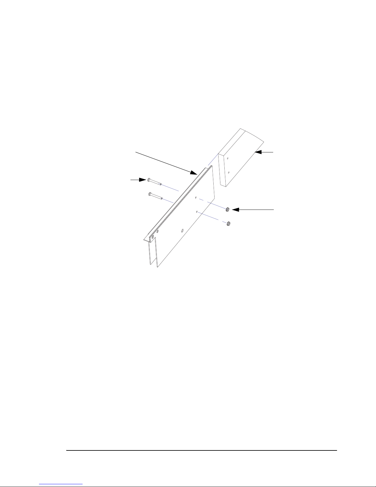
6. Secure the folding section of the gate arm onto the gate arm stabilizer (Figure 2.10)
Folding Section of
Gate Arm
Gate Arm Stablizer
Keps Nuts
Pan Head Screws
using two 10-24 x 1.5 pan head screws, and two 10-24 Keps nuts, as follows:
a. Align the holes on the folding gate arm section with the holes on the gate arm
stabilizer.
b. Insert a pan head screw into each hole.
c. Place a Keps nut on each screw and tighten to secure the folding gate arm.
Figure 2.10
Attaching the Folding Section to the Gate Arm Stabilizer
PosiDRIVE Security Gate ZMA-330, Ver. 6 Installing the Gate Arm • 31
Page 40
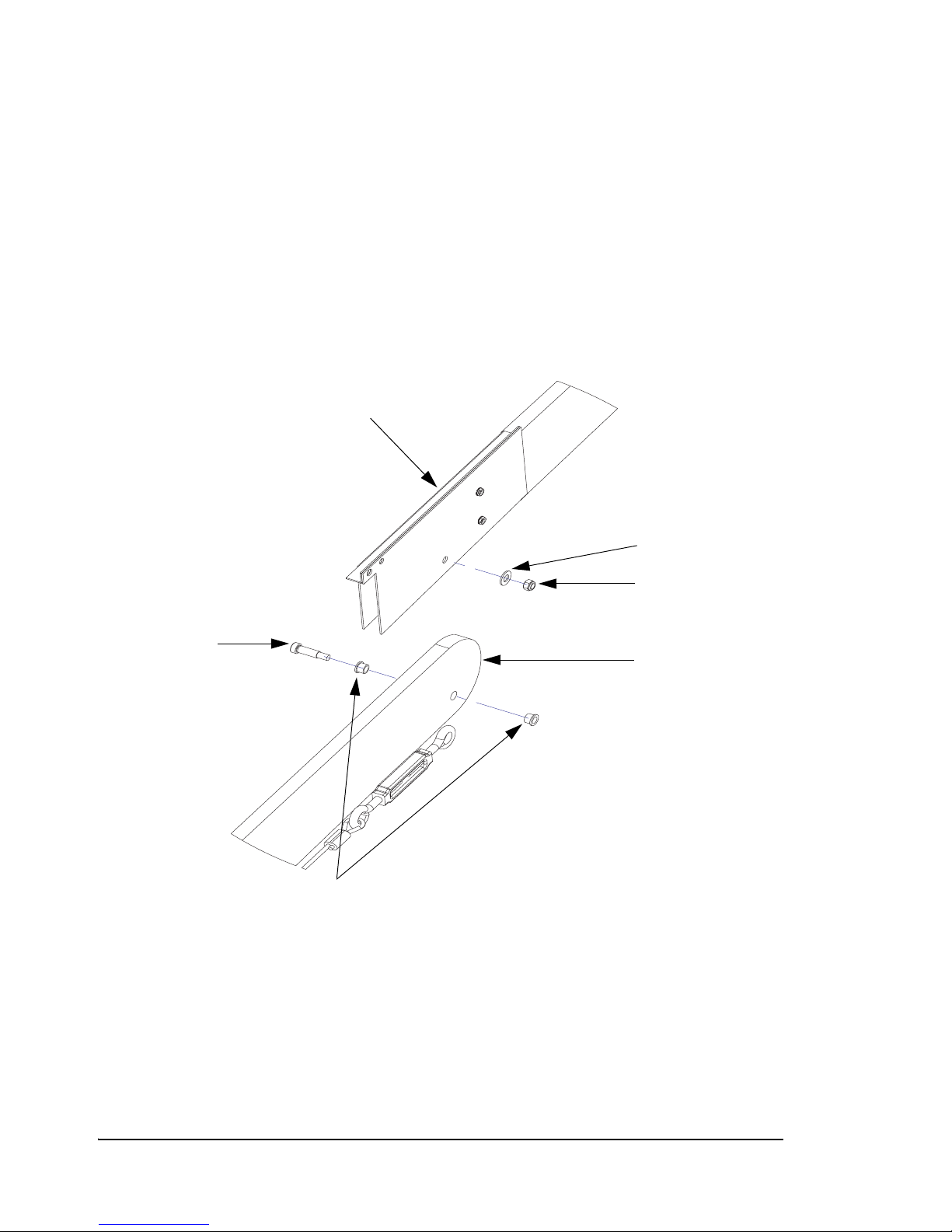
7. Attach the folding section with the gate arm stabilizer to the fixed section of the gate
Bushing
Shoulder Screw
Folding Section with
Gate Arm Stabilizer
Fixed Gate Arm
Section
Plain Washer
Nylock Hex Nut
(Figure 2.11) arm as follows:
a. Insert the two 3/8” bushings into either side of the hole on the fixed gate arm
section.
b. Align the hole on the bottom of gate arm stabilizer with the hole in the fixed arm
section.
c. Insert the shoulder screw into the bushings on the fixed gate arm section.
d. Secure the shoulder screw with a 3/8” plain washer and Nylock hex nut.
Figure 2.11
Attaching the Stabilized Folding Section to the Gate Arm Fixed Secton
32 • Installing the Gate Arm ZMA-330, Ver.6 PosiDRIVE Security Gate
Page 41
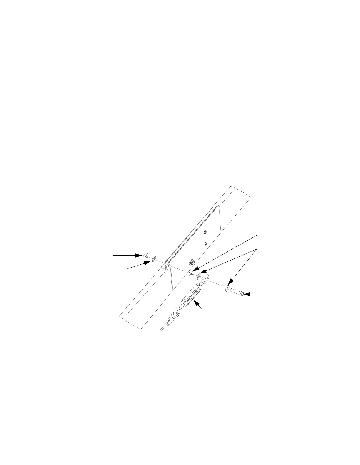
8. Attach the cable turnbuckle to the gate arm (Figure 2.12) as follows:
Hex Bolt
Plain Washers
Cable Turnbuckle
Hex Nut
Lock Washers
Hex Nut
a. Place a 3/8” plain washer onto the 3/8-16 x 1.5” hex bolt.
b. Insert the hex bolt into the eye of the cable turnbuckle.
c. Secure the bolt to the turnbuckle eye using a 3/8” plain washer and 3/8-16 hex
nut.
d. Insert the hex bolt into the gate arm stabilizer and loosely secure it with a 3/8"
lock washer and 3/8” hex nut.
e. Adjust the 3/8” hex nut until contact is made between the plain washer and the
turnbuckle eye. Do not tighten the nut against the turnbuckle eye.
f. Using 2 wrenches, tighten the 3/8” hex nut on the far side of the gate arm
stabilizer against the other 3/8” hex nut. When tight, the turnbuckle eye should
be free to move between the two 3/8” plain washers.
Figure 2.12
Attaching the Cable Turnbuckle to the Gate Arm
PosiDRIVE Security Gate ZMA-330, Ver. 6 Installing the Gate Arm • 33
Page 42
Change the Gate Arm Configuration
Mainspring
Pivot Bar
Mainshaft
Arm
Clamp
3/8” Bolts
and Nuts
Mainspring
Mainspring
Adjustment
Bar
Mainshaft
Bearing
Mainshaft Crank 1
Mainshaft Crank 2
The PosiDRIVE is factory-configured for left- or right-hand drive based on your site’s
requirements; however, if you receive a gate that is not configured properly, either return
the gate to Federal APD for replacement or have a qualified technician change the gate’s
configuration. No additional hardware is required to modify the gate’s configuration.
This task requires removing and reinstalling the gate arm. If the gate is
equipped with a standard gate arm, this task requires two technicians
to ensure safety and avoid damage to the equipment.
To change the gate arm configuration:
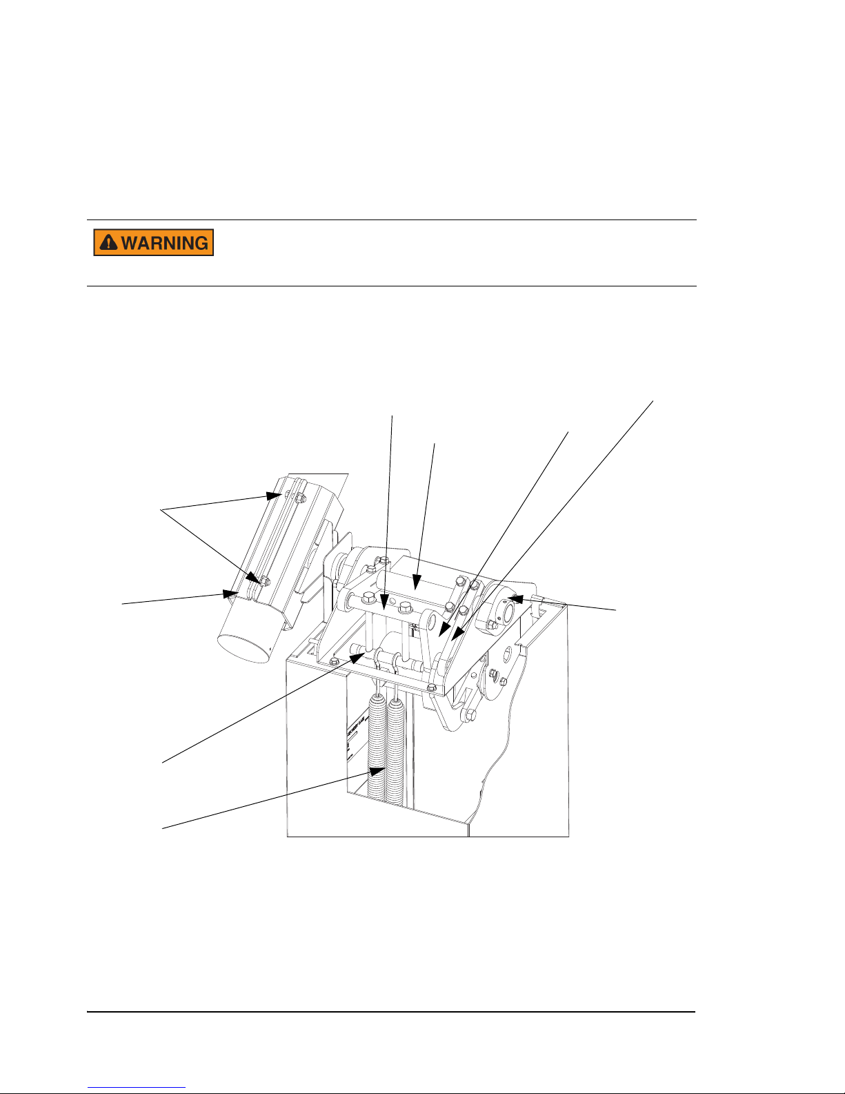
Figure 2.13
Gate Arm Configuration Components
1. Remove the enclosure door, so that the door interlock safety switch de-activates the
motor.
2. Turn off the power to the gate using the circuit breaker switch and disconnect the
backup battery assembly, if applicable.
3. Remove the enclosure cap. See “Removing the Enclosure Cap” on page 16.
34 • Installing the Gate Arm ZMA-330, Ver.6 PosiDRIVE Security Gate
Page 43
4. Manually raise the arm to the “up” position.
Remove the pivot bar
and set aside.
Slide the spring crank
along the mainshaft.
To avoid serious injury, make sure that the mechanism is fully locked
in the up position. See “Locking, Unlocking, and Advancing the Gate
Arm” on page 49.
5. Loosen the 3/8” bolts and nuts used to hold the arm clamp to the mainshaft.
6. Remove the gate arm and arm clamp and set aside.
7. Unhook all of the mainsprings. Remove the mainspring hooks from the bottom
flange first, and then unhook them from the mainspring connection bar
(Figure 2.13).
8. Loosen the six clamping bolts on the spring crank and on the mainshaft crank
(Figure 2.13).
9. Push the motor crank so that the mechanism moves towards the “down” arm
position just far enough so that the spring crank is above the frame mechanism
(Figure 2.13).
10. Slide the spring crank along the mainshaft until the mainspring pivot bar can be
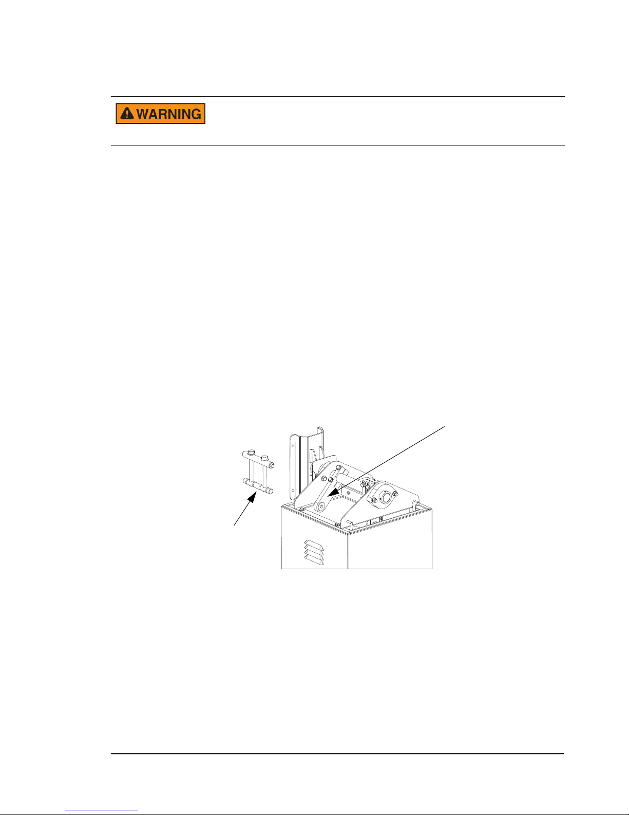
removed and then remove the pivot bar and set aside (Figure 2.14).
Figure 2.14
Pivot Bar
PosiDRIVE Security Gate ZMA-330, Ver. 6 Installing the Gate Arm • 35
Page 44
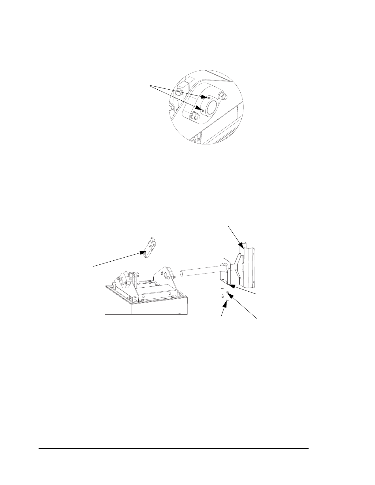
11. Loosen the set screws in the mainshaft bearing collars (Figure 2.15).
Loosen set screws
Slide mainshaft out of
the drive mechanism.
Remove spring crank
and set aside.
1/4-20 hex bolts.
Side shield.
1/4” flat
washers.
Figure 2.15
Set Screws
12. Remove the 1/4-20 hex bolts that hold the side shield in place (Figure 2.16).
13. Slide the mainshaft out of the drive mechanism (Figure 2.16).
14. Remove the spring crank (Figure 2.16) and set it aside.
Figure 2.16
Mainshaft Removal
15. Make sure that the surface of the mainshaft between the bearings is completely free
of grease and contamination. Clean the mainshaft thoroughly with isopropyl alcohol
if in doubt. The clamping mechanisms on the various cranks rely on static friction to
function properly and any contamination may cause them to slip.
16. Insert the mainshaft into the mainshaft bearing on the desired side of the gate.
36 • Installing the Gate Arm ZMA-330, Ver.6 PosiDRIVE Security Gate
17. Slide the mainshaft through the mainshaft bearing, the mainshaft crank 1 and the
mainshaft crank 2.
Page 45
18. Insert and tighten the 1/4” flat washers and 1/4-20 hex bolts that hold the side shield
in place.
19. Re-install the spring crank onto the mainshaft and slide the mainshaft into the
opposing mainshaft bearing.
20. Align the end of the mainshaft so that it is flush with the mainshaft bearing.
Note: A rubber hammer may be useful in moving the mainshaft through the
mainshaft bearing. Never use a steel hammer as it may damage the
mainshaft.
21. Re-install the mainspring pivot bar onto the spring crank.
Note: Make sure that the mainspring pivot bar is level and square with the
mainshaft crank and spring crank to avoid damaging the bearings.
22. Re-install the mainsprings. See “Adding, Removing, or Replacing the Mainsprings”
on page 52.
23. Re-install the gate arm. See “Installing the Gate Arm” on page 25.
a. Position and hold the gate arm in the fully vertical “up” position.
b. Tighten the mainshaft crank clamping bolts.
c. Tighten the spring crank clamping bolts.
24. Balance the gate arm. See “Setting the Mainsprings” on page 38.
25. Turn on the power to the gate and re-connect the backup battery assembly, if
applicable.
To avoid injury, stay clear of the gate arm path. When the gate powers
up, the gate arm raises and lowers as part of the homing process.
26. Replace the enclosure cap.
27. Replace the enclosure door.
28. Verify that the positioning of the arm is correct.
PosiDRIVE Security Gate ZMA-330, Ver. 6 Installing the Gate Arm • 37
Page 46
Setting the Mainsprings
The mainsprings are a vital part of the operation of the PosiDRIVE gate. They
counterbalance the weight of the arm, allowing the PosiDRIVE to operate arms as large
as 20 feet (6 m) with a relatively low powered motor. Too much spring (overbalance) or
too little spring (underbalance) can adversely affect the operation of the PosiDRIVE.
After installing the gate arm, set the mainsprings to ensure optimum gate performance.
To avoid serious injury, two technicians are required to perform this
task: one to handle the gate arm and the other to make mainspring
adjustments.
To set the mainsprings:
1. Open the gate enclosure.
2. Disconnect the circuit breakers to turn power off to the gate and disconnect the
battery backup if applicable.
3. Manually advance the drive mechanism out of the “locked” position so the arm and
linkage are free to move. See “Locking, Unlocking, and Advancing the Gate Arm”
on page 49.
4. Manually advance the arm to a 45 degree angle, but do not let go of the gate arm.
If the gate does not have the correct number of mainsprings installed
or if they are not adjusted properly, the gate arm can spring upward or
fall to the down position and damage the drive mechanism. To prevent
damage to the gate, carefully support the arm as you slowly lower it.
If you feel the gate arm pulling upward or it feels like it will fall if you let it go,
return the arm to the upright position and proceed with adjustment.
If the gate arm feels balanced, slowly let it go. If it remains stationary at 45 degrees,
the mainspring tension is correct. Replace the enclosure cap, turn on the power to
the gate, and close the enclosure door.
38 • Setting the Mainsprings ZMA-330, Ver.6 PosiDRIVE Security Gate
Page 47
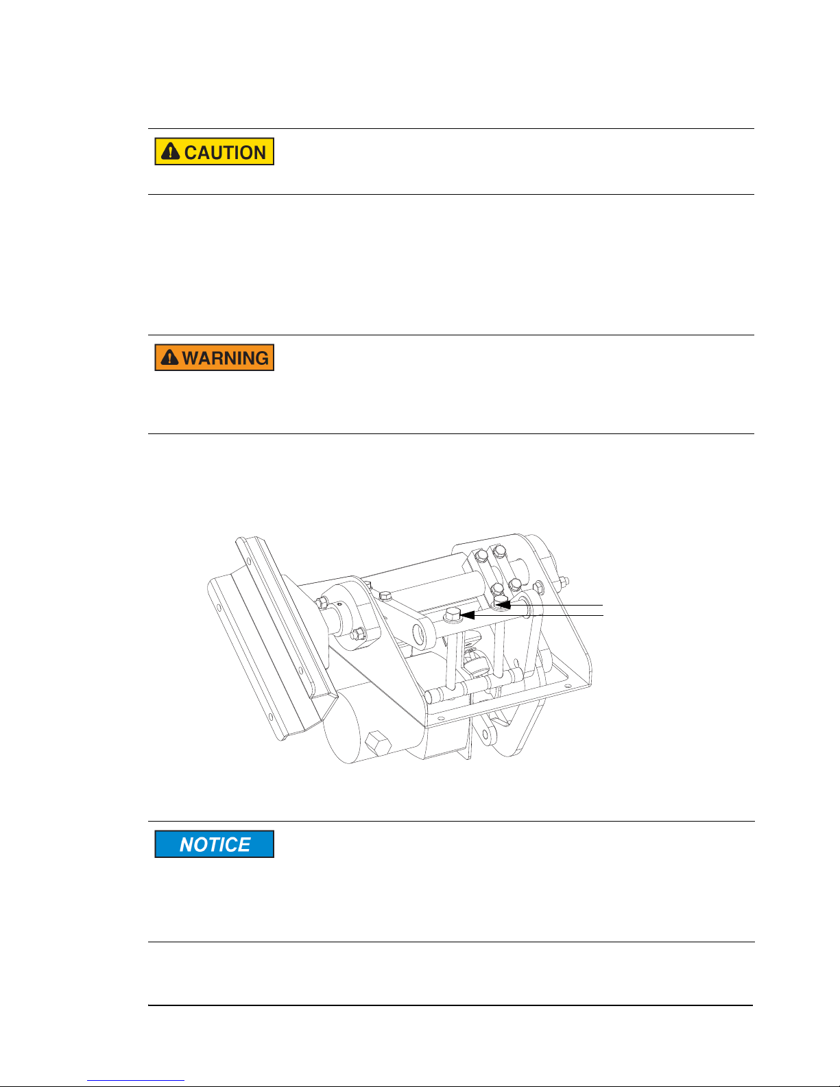
5. Adjust the mainspring tension as follows:
Spring Adjustment Bolts
To avoid binding the spring adjustment bolts (Figure 2.17), make
adjustments evenly; that is, turn each bolt once or twice and then apply
the same number of turns to the other bolt.
◆ To increase spring tension, turn the spring adjustment bolts (Figure 2.17)
clockwise.
◆ To decrease spring tension, turn the spring adjustment bolts (Figure 2.17)
counterclockwise.
Pay attention to the mainspring connection bar and the adjustment
bolts. If you are reducing spring tension, NEVER relax the mainsprings
to the point where they may detach from the connection bar. The
mainsprings should never be fully relaxed and loose with the gate in
the “up” position.
Adjust the bolts until the gate holds the arm at the 45 degree angle.
Figure 2.17
Spring Adjustment Bolts
If, at the limits of adjustment, the gate arm does not balance, add or
remove a mainspring. See “Adding, Removing, or Replacing the
Mainsprings” on page 52.
If you are increasing the tension and the adjustment is approaching the
limit, consider adding a mainspring and using a lower adjustment to
reduce the stress on the mainsprings.
PosiDRIVE Security Gate ZMA-330, Ver. 6 Setting the Mainsprings • 39
Page 48

Disabling the Locked-Down Feature (Optional)
The PosiDRIVE Security Gate drive mechanism is designed to lock at the limits of
travel. This feature prevents the gate arm from being moved manually when the gate is
in the fully up or fully down position, which ensures:
■ The safety of the technician(s) that perform maintenance and repairs on the gate. For
example, many procedures call for locking the gate in the up position to ensure the
gate arm does not fall and the drive mechanism does not move while maintenance or
repairs are preformed.
■ The security of the facility by preventing unauthorized entry. Although the locking
the gate in the down position provides a higher level of security, it also increases the
potential for damage to the gate if someone tries to manually raise the gate arm. As
with any gate, applying an upward force to the outer end of the arm generates
enormous force back through the drive mechanism that can damage the gate.
Placing one or more washers under the down rubber bump stop (Figure 2.18)
prevents the gate from becoming fully locked in the down position, yet allows the
gate to come close enough to the locked position to provide significant resistance;
thus, deterring most attempts to gain unauthorized access.
To disable the fully locked down position:
1. Open the gate enclosure. See “Opening the Enclosure Door” on page 16.
2. Set the Auto/Manual Switch (Figure 1.6, on page 11) to the Manual position to
raise the gate arm to the fully up position.
3. Reactivate the door safety switch by depressing the plunger.
4. Turn off the power to the gate using the circuit breaker switch and disconnect the
backup battery assembly.
5. Remove the enclosure cap. See “Removing the Enclosure Cap” on page 16.
40 • Disabling the Locked-Down Feature (Optional) ZMA-330, Ver.6 PosiDRIVE Security Gate
Page 49
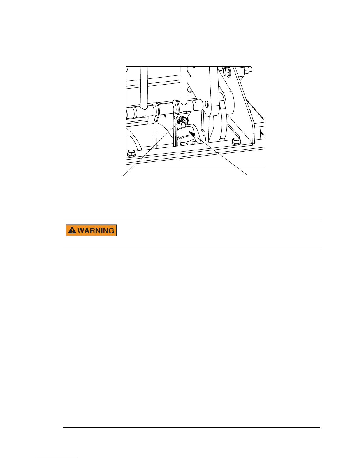
6. Remove the down rubber bump stop (Figure 2.18).
1/4” Flat Washer Rubber Bump Stop
Figure 2.18
Down Bump Stop
7. Place one or more 1/4" flat washer(s) on the neck of the down rubber bump stop and
return the bump stop to its original position.
To ensure safety, do not place washers under the Up Bump Stop. You
must be able to place the gate in the fully locked up position to avoid
serious bodily injury.
8. Ensure all technicians are clear of the drive mechanism and the gate arm path.
9. Connect the battery back up, turn on the circuit breaker switch, and pull out the door
safety switch. The gate powers up and begins the homing process in which the arm
travels up and down.
10. Once the gate arm settles in the down position, fully depress the door safety switch,
disconnect the battery backup, and turn off the circuit breaker switch again.
11. Attempt to raise the arm manually and observe the resistance encountered. If the
arm cannot be moved, add another washer. If the arm moves too easily remove a
washer. Be sure the lock the arm in the up position before adding or removing
washers.
PosiDRIVE Security Gate ZMA-330, Ver. 6 Disabling the Locked-Down Feature (Optional) • 41
Page 50
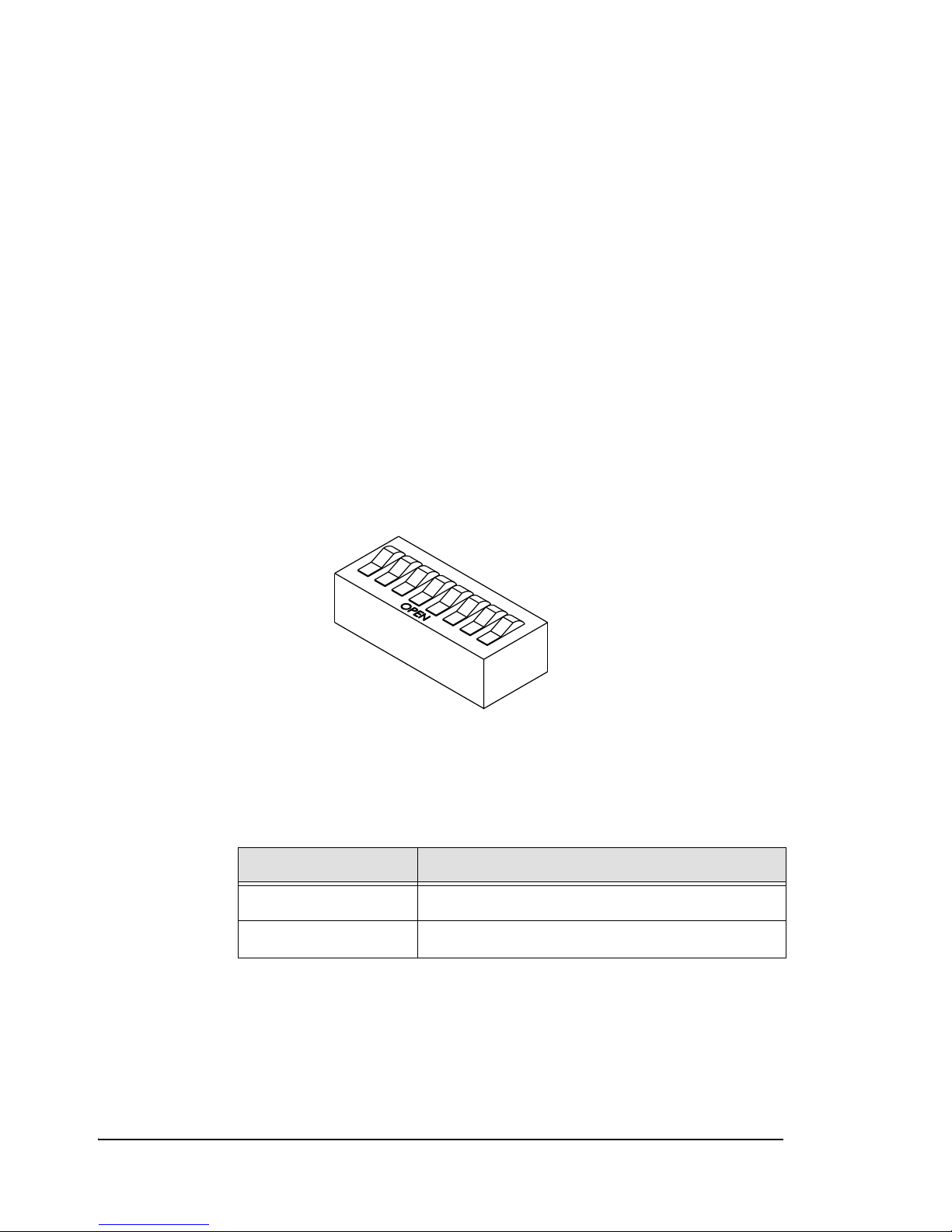
12. When the gate arm provides the appropriate amount of resistance, reconnect power
and close up the gate as follows:
a. Ensure all technicians are clear of the drive mechanism and the gate arm path.
b. Replace the enclosure cap.
c. Connect the battery backup.
d. Turn on the circuit breaker switch.
e. Close the enclosure door.
Setting the DIP Switches
Set the SW2 DIP switches on the PosiDRIVE Controller (Figure 1.9, on page 14) for the
gate to function as intended. Figure 2.19 shows the DIP switches in the “open” position.
Descriptions of the DIP switch functions follow the illustration.
Note: DIP switch 2 is unused.
Figure 2.19
DIP switches in the Open Position
DIP Switch 1: Vend Counts
The following table lists the DIP switch positions to enable or disable vend
counts.
Table 2-3 —
Vend Count Enabled/Disabled DIP Switch Settings
Values DIP Switch Positions
Vend counts enabled DIP switch 1 closed
Vend counts disabled DIP switch 1 open
42 • Setting the DIP Switches ZMA-330, Ver.6 PosiDRIVE Security Gate
Page 51

DIP Switches 3 and 4: Backout Gate Reset Time
The following table lists the DIP switch positions to set the amount of time,
from 15 seconds to 60 seconds, that the gate stays up to let the patron enter the
facility. If DIP switch 7 is closed, enabling Backout Gate Arm Timeout, the gate
automatically closes if loop-B does not detect the vehicle within the configured
time.
Note: This setting only affects the amount of time the patron has to pull onto
loop-B. Once the patron pulls onto loop B, the gate arm stays up until
the patron clears the loop.
If DIP switch 7 is open, disabling Backout Gate Arm Timeout, DIP switches 3
and 4 are not applicable; the gate arm stays up until the patron clears loop B.
Table 2-4 —
Backout Gate Reset Time DIP Switch Settings
Values DIP Switch Positions
15 seconds DIP switches 3 and 4 closed
30 seconds DIP switch 3 open, DIP switch 4 closed
45 seconds DIP switch 3 closed, DIP switch 4 open
60 seconds DIP switches 3 and 4 open
DIP Switches 5 and 6: Gate Arm Length
The following table lists the DIP switch positions for the various gate arm
lengths.
Table 2-5 — Gate Arm Length DIP Switch Settings
Values DIP Switch Positions
10-12 feet (3.05m -
3.66m)
14-16 feet (4.27m -
4.88m)
DIP switch 5 open, DIP switch 6 closed
DIP switch 5 closed, DIP switch 6 open
18-20 feet (5.49m -
6.10m)
PosiDRIVE Security Gate ZMA-330, Ver. 6 Setting the DIP Switches • 43
DIP switch 5 open, DIP switch 6 open
Page 52

DIP Switch 7: Backout Gate Arm Timeout
The following table lists the DIP switch positions to enable or disable Backout
Gate Arm Timeout.
Table 2-6 —
Backout Gate Arm Timeout DIP Switch Settings
Values DIP Switch Positions
Backout Gate Arm
Timeout disabled - gate
arm stays up until
vehicle clears loop B
Backout Gate Arm
Timeout enabled - gate
arm closes after time
specified with DIP
switches 3 and 4
elapses if vehicle is not
detected on loop B
DIP switch 7 open
DIP switch 7 closed
DIP Switch 8: Auto-Raise
The following table lists the DIP switch positions to enable or disable the autoraise function.
Table 2-7 — Auto-Raise Function DIP Switch Settings
Values DIP Switch Positions
Automatically raise gate
during a power failure
Do not raise gate during
a power failure
DIP switch 8 open
DIP switch 8 closed
44 • Setting the DIP Switches ZMA-330, Ver.6 PosiDRIVE Security Gate
Page 53

CHAPTER 3
Maintenance and Repair
This chapter contains the following topics:
Maintenance and Repair Overview ...................................................................46
Performing Preventive Maintenance .................................................................46
Grease the Connection Rod Bearings .........................................................47
Troubleshooting a Problem ...............................................................................48
Locking, Unlocking, and Advancing the Gate Arm..........................................49
Adding, Removing, or Replacing the Mainsprings...........................................52
Aligning the Drive Mechanism .........................................................................54
PosiDRIVE Security Gate ZMA-330, Ver. 6 Maintenance and Repair • 45
Page 54

Maintenance and Repair Overview
To keep the gate functioning properly, perform monthly and semi-annual preventive
maintenance, such as checking the mechanical components and greasing bearings.
Moving parts can cause bodily injury, and hazardous voltage can
shock, burn, or cause death. Turn off the power to the gate and
disconnect the backup battery before performing any maintenance or
repairs.
If the gate does not function properly, refer to the troubleshooting table provided in this
chapter (Table 3-8) for help diagnosing and repairing the issue.
Many gate adjustment and repair tasks call for advancing the gate arm to the fully up or
fully down position and locking the drive mechanism into place. If this done via a raise/
lower switch, the drive mechanism automatically locks into the place; however, some
tasks require moving the gate arm manually, in which case you must lock the drive
mechanism by hand.
This chapter explains how to perform the following maintenance and repair tasks:
■ “Performing Preventive Maintenance” on page 46
■ “Troubleshooting a Problem” on page 48
■ “Locking, Unlocking, and Advancing the Gate Arm” on page 49
■ “Adding, Removing, or Replacing the Mainsprings” on page 52
■ “Aligning the Drive Mechanism” on page 54
Performing Preventive Maintenance
To keep the gate functioning properly, perform the following preventive maintenance tasks:
■ Monthly:
◆ Inspect all warning labels to ensure that all are clear and readable.
◆ Inspect the gate enclosure for damage to ensure structural integrity of gate
enclosure.
◆ Check mainspring tension to ensure that the gate is still properly balanced.
■ Semi-annually:
◆ Check tightness on all fasteners on the drive system and gate arm, and check the
gate mounting bolts to ensure the integrity of the drive mechanism.
◆ Grease mainshaft bearings to maintain bearing capacity and prevent internal
corrosion. See “Grease Mainshaft Bearings” on page 47.
◆ Grease connecting rod bearings to maintain bearing capacity and prevent
internal corrosion. See “Grease the Connection Rod Bearings” on page 47.
46 • Maintenance and Repair Overview ZMA-330, Ver.6 PosiDRIVE Security Gate
Page 55
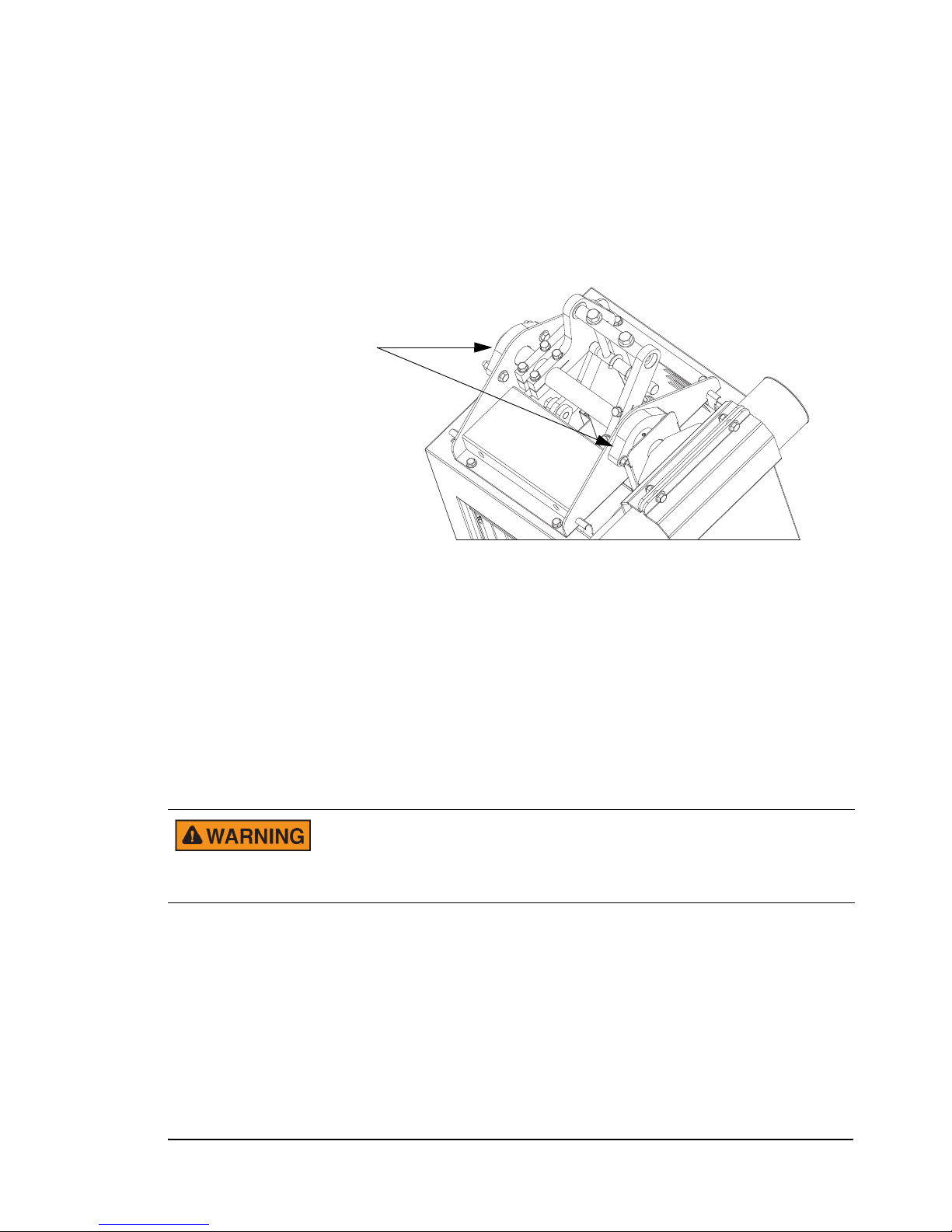
Grease Mainshaft Bearings
Mainshaft
Bearings
To grease the mainshaft bearings:
1. While the gate arm is in the down position, open the enclosure door and remove the
enclosure cap. See “Removing the Enclosure Cap” on page 16.
2. Use a grease gun to inject heavy-duty synthetic grease into the grease fitting on each
bearing housing.
Grease the Connection Rod Bearings
To grease the connection rod bearings:
1. Advance the gate to the up position. See “Locking, Unlocking, and Advancing the
Gate Arm” on page 49.
2. Remove the enclosure door and cap. See “Removing the Enclosure Cap” on
page 16.
3. Have another technician hold the gate arm in the up position.
Holding the gate arm in the up position is necessary to avoid serious
injury and damage to the gate. Once the connecting rod is removed,
the gate arm is no longer balanced and can easily fall from the up
position.
PosiDRIVE Security Gate ZMA-330, Ver. 6 Performing Preventive Maintenance • 47
Page 56
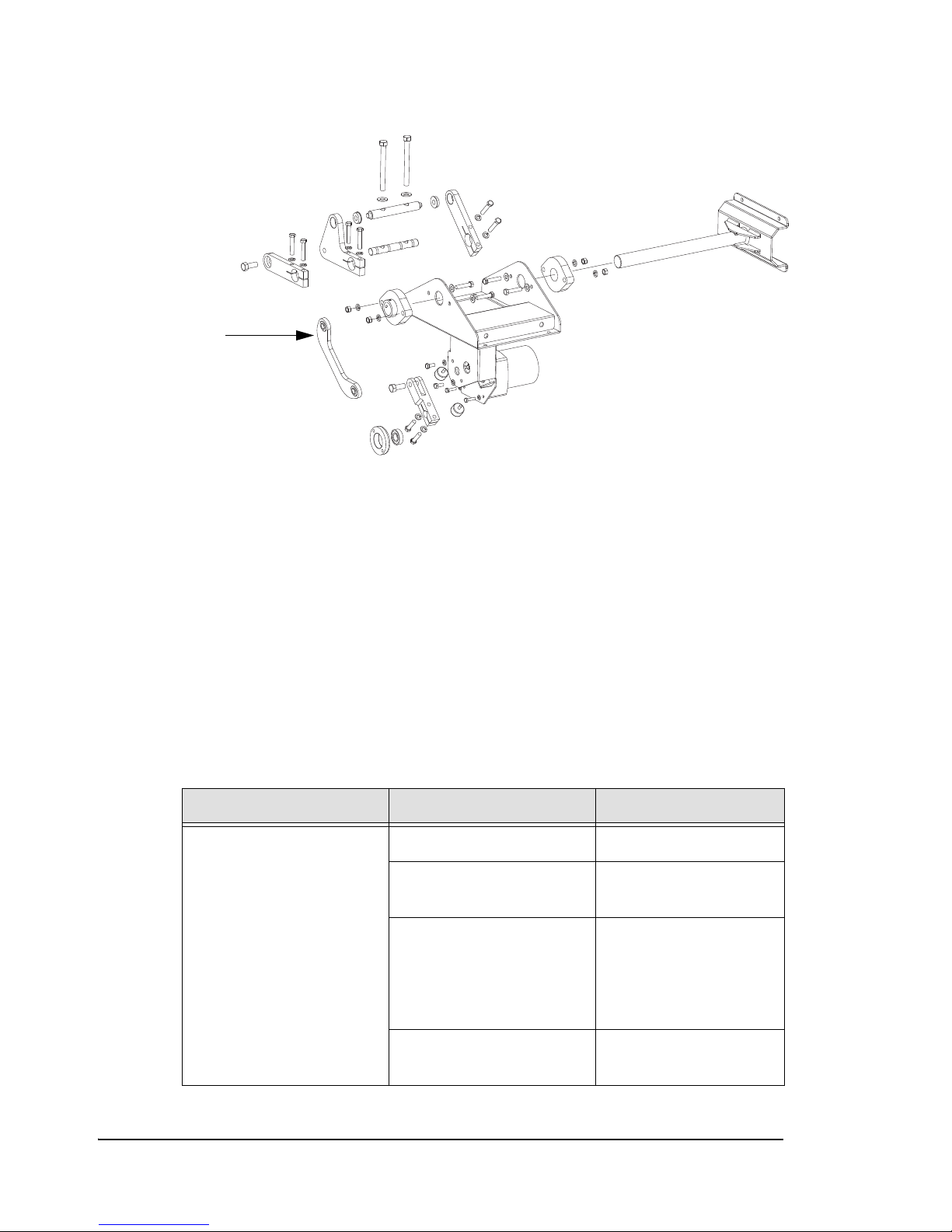
4. Unbolt and remove the connecting rod.
Connecting Rod
5. Turn the spherical bearing element within the bearing housing so that the bearing
surface is visible.
6. Apply bearing grease to the bearing surface and move the bearing element around to
spread the grease evenly within the bearing housing.
7. Replace the connecting rod and connecting rod bolts.
Troubleshooting a Problem
If the PosiDRIVE gate fails to operate properly, use the following table to troubleshoot
the problem. If you are still unable to correct the problem, contact your distributor. If
you are the distributor, contact Federal APD. See Appendix A,“Product Support”.
Problem Potential Cause Solution
The gate is not operating. The main power is off. Turn the power on.
Table 3-8 —
The wiring connections may
be loose.
The breaker switch may be
tripped.
The door safety switch is
out.
Troubleshooting
Check all wiring
connections.
Reset the breaker switch.
Caution: if this is the
problem, the cause of the
current overload must be
identified and fixed.
Make sure the access
door is on and secured.
48 • Troubleshooting a Problem ZMA-330, Ver.6 PosiDRIVE Security Gate
Page 57

Table 3-8 — Troubleshooting (Continued)
Problem Potential Cause Solution
The gate arm is not properly
positioned, i.e., the gate arm
is not horizontal when
linkage is in the full down
position.
The gate does not operate
smoothly, landing
excessively hard in the up
or down positions.
The gate arm begins to
raise when commanded,
and then stops and returns
to the down position.
The gate arm begins to
lower, and then stops and
returns to the raised
position; this happens
repeatedly.
The drive mechanism has
slipped.
The mainspring is
imbalanced.
There is a severe negative
mainspring imbalance.
There is a severe positive
mainspring imbalance.
Locking, Unlocking, and Advancing the Gate Arm
Adjust the drive
mechanism. See
“Aligning the Drive
Mechanism” on page 54.
See “Setting the
Mainsprings” on page 38.
See “Setting the
Mainsprings” on page 38.
See “Setting the
Mainsprings” on page 38.
The PosiDRIVE Security Gate drive mechanism is designed to lock at the limits of
travel. This feature prevents the gate arm from being moved manually when the gate is
in the fully up or fully down position, which ensures:
■ The safety of the technician(s) that perform maintenance and repairs on the gate. For
example, many procedures call for locking the gate in the up position to ensure the
gate arm does not fall and the drive mechanism does not move while maintenance or
repairs are preformed.
■ The security of the facility by preventing someone from manually lifting the gate
arm to gain unauthorized access or to exit without paying a fee.
PosiDRIVE Security Gate ZMA-330, Ver. 6 Locking, Unlocking, and Advancing the Gate Arm • 49
Page 58
When performing maintenance or repairs, using the Auto-Manual switch on the
PosiDRIVE controller (Figure 1.6, on page 11) is the easiest way to move the gate arm
into the fully up or fully down position. Since the enclosure door must be open to access
the Auto-Manual switch, and the door safety switch disables the drive motor when the
door is open, this method requires bypassing the door safety switch (see “Safety Switch”
on page 12).
To avoid serious injury, always make sure that all technicians are clear
of the drive mechanism and the path of the gate arm before bypassing
the door safety switch. If a person’s hand is inside the gate enclosure
when the drive mechanism actuates, serious injury, including
dismemberment, can occur.
Some procedures, such as setting the mainsprings or manually opening the gate during a
power failure, require manually advancing the gate arm. Manually advancing the gate
arm requires bumping the linkage out of the locked position.
To avoid serious injury, always take the following precautions when
manually advancing the gate arm:
• Terminate all power to the gate; that is, turn off the circuit breaker
and disconnect the battery backup (see “Electrical Components” on
page 10). If the battery backup is not disconnected and the gate is
programmed to automatically raise during a power failure, the drive
mechanism begins raising the gate arm 10 seconds after the circuit
breaker is turned off.
• Have a second technician secure the position of the gate arm. This
is especially important when lowering the gate arm. After bumping
the linkage out of the locked position, the weight of the arm can
cause the gate to descend. If your hand is not clear of the drive
mechanism, serious injury, including dismemberment, can occur.
To manually advance the gate arm:
1. Remove the gate enclosure cap. See “Removing the Enclosure Cap” on page 16.
2. If you are moving the gate arm from the fully up position, have a second technician
secure the gate arm so that it does not descend while your hands are near the drive
mechanism.
50 • Locking, Unlocking, and Advancing the Gate Arm ZMA-330, Ver.6 PosiDRIVE Security Gate
Page 59
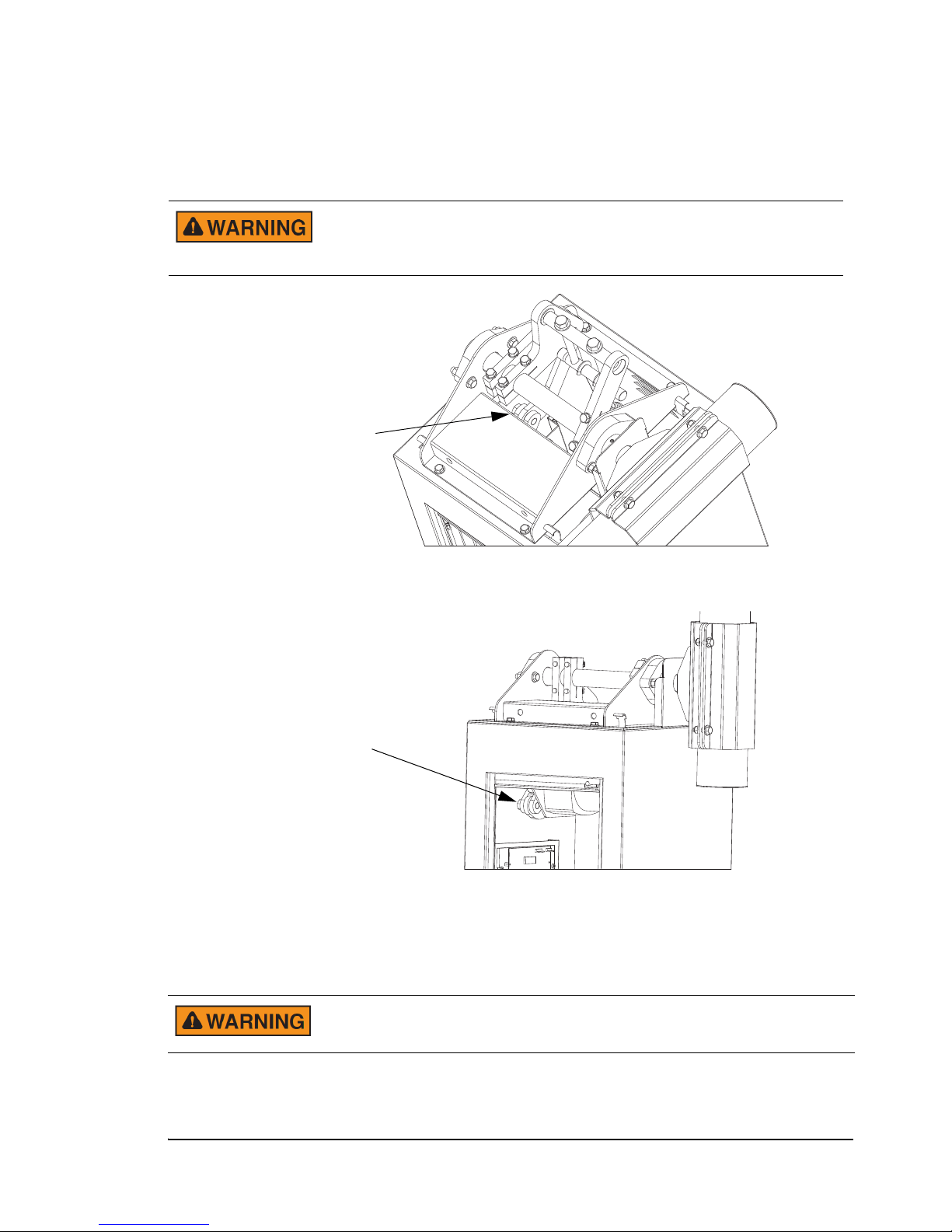
3. Push the motor crank hinge, shown in Figure 3.1 and Figure 3.2, to advance the
Point at which you can move
the mechanism to manually
advance the gate arm out
of the down position
To prevent a serious pinching injury including dismemberment, use
care when working with the drive mechanism and alway terminate
power prior to performing maintenance or repairs.
Point at which you can move
the mechanism to manually
advance the gate arm out of
the up position
mechanism out of the locked position.
Figure 3.1
Motor Crank Position when the Gate Arm is Down
Figure 3.2 Motor Crank Position when the Gate Arm is Up
4. Manually raise or lower the gate arm as far as possible.
5. Pull the motor crank to lock the drive mechanism linkage. When locked, the hinges
in the linkage are aligned.
PosiDRIVE Security Gate ZMA-330, Ver. 6 Locking, Unlocking, and Advancing the Gate Arm • 51
If the mainsprings are not installed, locking the gate arm when it is in
the up position is especially important to avoid serious injury.
Page 60
Adding, Removing, or Replacing the Mainsprings
The PosiDRIVE Security Gate is equipped with two or more mainsprings that provide
the necessary tension to operate the gate arm. The required number of mainsprings
depends upon the length of the gate arm. The following table lists the number of
mainspring required for each available gate arm length:
Gate Arm Length Number of Mainsprings
10 feet 2
12 feet 2
14 feet 3
16 feet 3
18 feet 4
20 feet 4
The mainsprings are installed at the factory. However, this procedure is provided in case
you need to add, remove, or replace a mainspring.
To prevent serious bodily injury:
• Two people are required to add, remove, or replace a mainspring:
one to hold the gate arm in the up position and the other to handle
the mainspring installation or removal.
• Lock the gate arm in the up position as described in “Locking,
Unlocking, and Advancing the Gate Arm” on page 49.
To install the mainsprings:
1. Open the gate enclosure and remove the enclosure cap. See “Removing the
Enclosure Cap” on page 16.
2. If the gate arm is installed, the arm must be raised to up position. See “Locking,
Unlocking, and Advancing the Gate Arm” on page 49.
52 • Adding, Removing, or Replacing the Mainsprings ZMA-330, Ver.6 PosiDRIVE Security Gate
Page 61
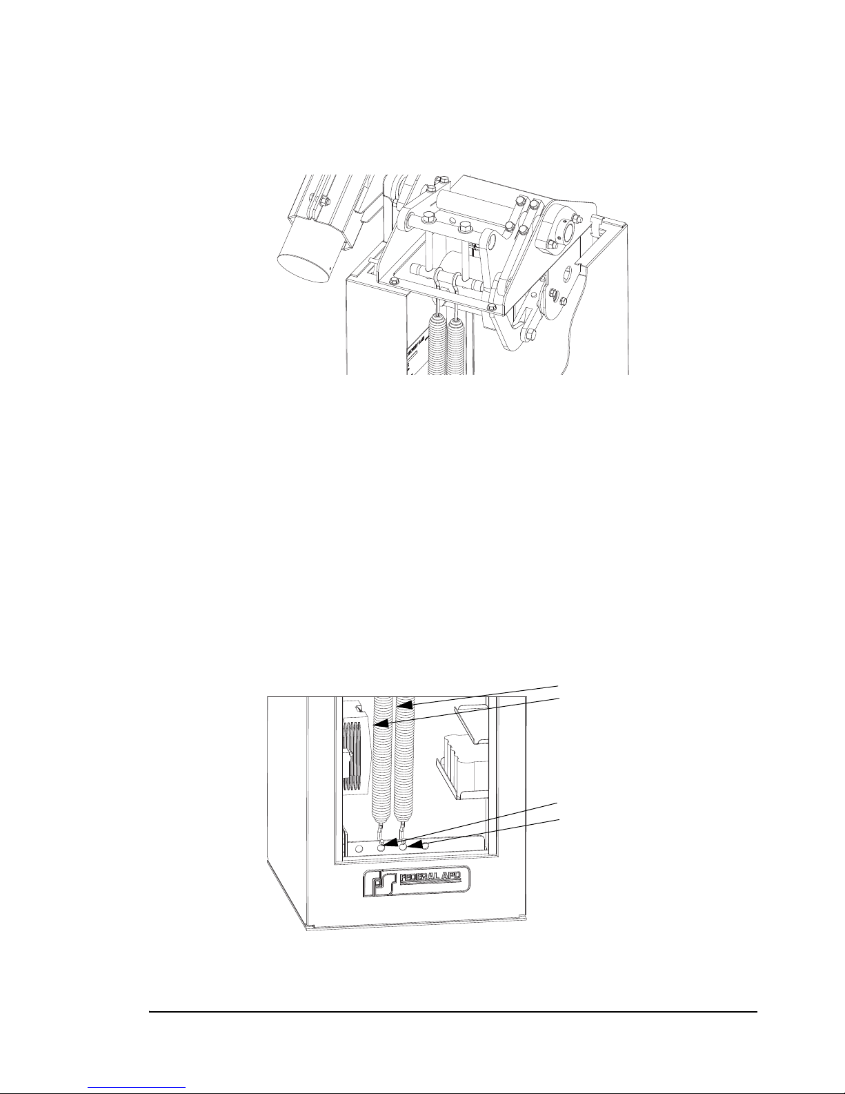
3. From inside the gate enclosure, attach the top hook of the mainspring to the
Mainsprings
Mainspring Attachment Points
mainspring connection bar.
Figure 3.3
Mainspring Connection Bar
4. Hook the lower end of the mainspring into the corresponding hole in the flange at
the bottom of the gate (Figure 3.4). Make sure that the hole used in the flange
corresponds with the position on the mainspring connection bar, i.e., first hole with
first position, second hole with second position, etc.
Note: If the gate requires only two mainsprings, place the springs in the 2nd and
3rd position.
To remove a mainspring, reverse the procedure. Remove the mainspring hook from
the bottom flange first, and then unhook it from the mainspring connection bar.
Note: After the gate arm is installed, to achieve optimal balance of the gate arm
and proper operation of the PosiDRIVE gate, set the mainsprings as
described in “Setting the Mainsprings” on page 38.
Figure 3.4
Mainspring Attachment Points
PosiDRIVE Security Gate ZMA-330, Ver. 6 Adding, Removing, or Replacing the Mainsprings • 53
Page 62
Aligning the Drive Mechanism
The PosiDRIVE is aligned at the factory; however, certain repairs may result in the need
to realign the gate. Alignment is required when the gate arm is not parallel with the
ground. This procedure requires two technicians.
To align the gate:
1. Open the gate enclosure and remove the enclosure cap. See “Removing the
Enclosure Cap” on page 16.
2. Use the Auto-Manual switch to raise the gate arm to the fully up and locked
position. See “Locking, Unlocking, and Advancing the Gate Arm” on page 49.
To avoid serious injury, make sure that the drive mechanism is fully
locked in the up position.
3. Turn off circuit breaker switch and disconnect the backup battery assembly to
terminate all power to the gate. See “Electrical Components” on page 10.
4. Unhook all of the mainsprings from the bottom flange (Figure 3.4, on page 53).
5. With the assistance of a second person, bump the drive mechanism out of the locked
position and slowly lower the gate arm to the horizontal position. See “Locking,
Unlocking, and Advancing the Gate Arm” on page 49.
6. While the second person supports the arm, manually bump the linkage into the fully
“locked down” position. See “Locking, Unlocking, and Advancing the Gate Arm”
on page 49.
54 • Aligning the Drive Mechanism ZMA-330, Ver.6 PosiDRIVE Security Gate
Page 63
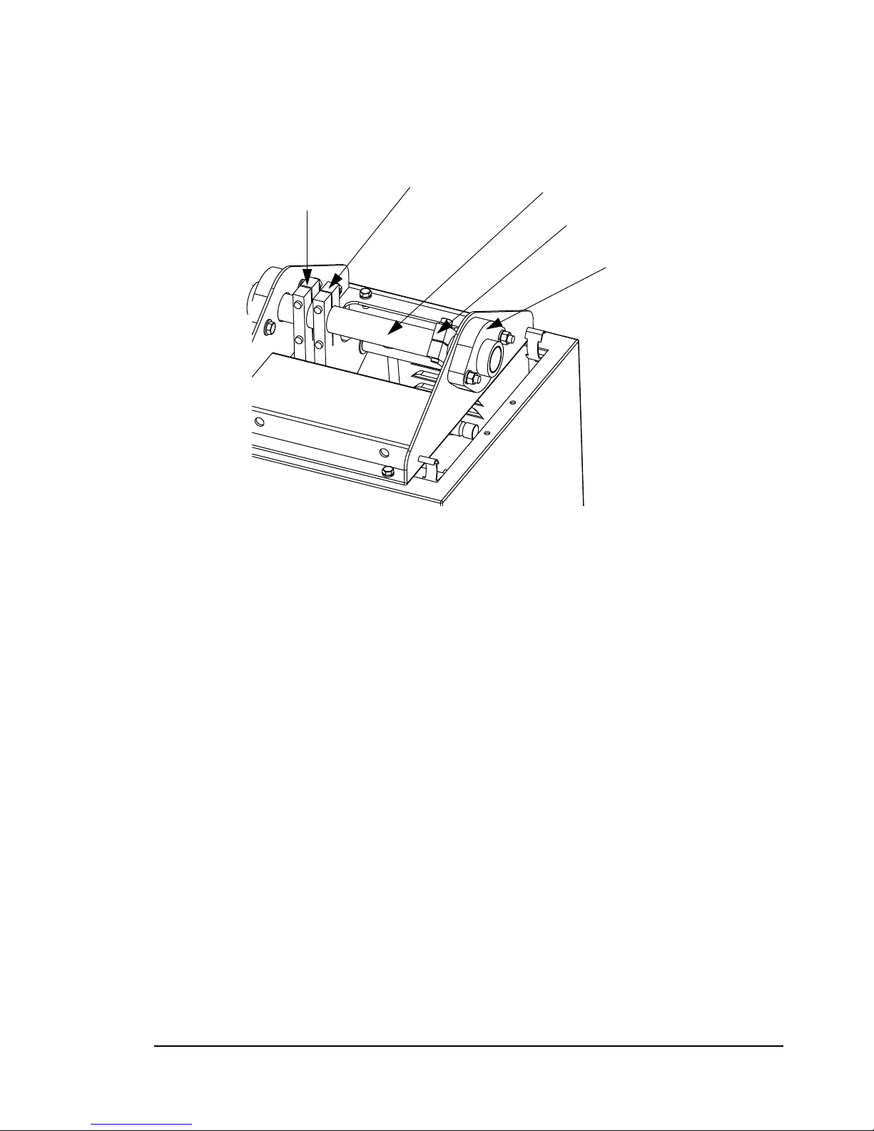
7. Loosen the clamping bolts on both of the mainshaft cranks and the mainspring
Mainshaft Crank
Part 1
Mainshaft Crank
Part 2
Mainshaft
Mainspring
Crank
Mainshaft Bearing
crank.
Figure 3.5
Drive Mechanism Alignment
8. While the second technician holds the gate arm at the desired down position, tighten
all of the bolts on the cranks.
9. Carefully bump the linkage out of the locked position, manually raise the arm to the
up position, and lock it into place. See “Locking, Unlocking, and Advancing the
Gate Arm” on page 49.
10. Re-install the mainsprings. See “Adding, Removing, or Replacing the Mainsprings”
on page 52.
PosiDRIVE Security Gate ZMA-330, Ver. 6 Aligning the Drive Mechanism • 55
Page 64

56 • Aligning the Drive Mechanism ZMA-330, Ver.6 PosiDRIVE Security Gate
Page 65

APPENDIX A
Product Support
This appendix contains the following topics:
Getting Help ......................................................................................................58
Accessing the Distributor Resource Center.......................................................59
PosiDRIVE Security Gate ZMA-330, Ver. 6 Product Support • 57
Page 66

Getting Help
If you have a product question that is not addressed in this manual, contact your Federal
APD distributor. If you are a distributor or you do not have a distributor, call Federal
APD Product Support at one of the telephone numbers listed in Table A-1.
Whether you call, write, or fax, please have the following information available:
■ A description of the events and the order in which they occurred
■ The type of hardware you are using, with serial number and model number
■ Firmware version, if applicable
■ The type and configuration of software you are using
■ Original sales order number
■ Any messages that appear on your display screen and the exact wording
■ Project name
■ SRO number, if applicable
Table A-1 —
Federal APD Product Support Phone Numbers
Location Phone Fax
United States (800) 527-4768 (248) 374-9610
Canada (800) 331-9144 (248) 374-9610
Central America
South America
Asia
Australia
China
Hong Kong
India
Indonesia
Korea
Malaysia
New Zealand
Philippines
Singapore
Tai wa n
Thailand
Vietnam
(248) 374-9629 (248) 374-9610
(852) 2671-9880 (852) 2402-1912
58 • Getting Help ZMA-330, Ver.6 PosiDRIVE Security Gate
Page 67

Table A-1 — Federal APD Product Support Phone Numbers (Continued)
Location Phone Fax
Bahrain
(248) 374-9629 (248) 374-9610
Egypt
Europe
Greece
Greenland
Iceland
Jordan
Saudi Arabia
Turkey
UAE
Accessing the Distributor Resource Center
If you are a distributor, visit the Distributor Resource Center on the Federal APD Web
site at www.federalapd.com
■ Access product information
■ Download software upgrades when they are available
■ Review Frequently Asked Questions.
Note: A user ID and password are required to access the Distributor Resource Center.
Obtain a user ID and password from Federal APD Sales Administration at
(248) 374-9600.
to:
PosiDRIVE Security Gate ZMA-330, Ver. 6 Accessing the Distributor Resource Center • 59
Page 68

60 • Accessing the Distributor Resource Center ZMA-330, Ver.6 PosiDRIVE Security Gate
Page 69

APPENDIX B
Order and Repair Procedures
This appendix contains the following topics:
Placing an Order................................................................................................62
Requesting a Repair...........................................................................................62
Locate a Part Number .................................................................................63
Mainsprings..........................................................................................64
Enclosure..............................................................................................65
Electrical Components .........................................................................68
Standard Gate Arm...............................................................................70
Folding Gate Arm.................................................................................73
Drive Mechanism .................................................................................78
PosiDRIVE Security Gate ZMA-330, Ver. 6 Order and Repair Procedures • 61
Page 70

Placing an Order
To place an order:
1. Determine the applicable part number. See “Locate a Part Number” on page B-63.
If the part number is not included in this manual, refer to the Federa APD Price
Book or contact Order Entry and Preparation for part names, part numbers, prices,
and delivery information at one of the following telephone numbers:
◆ Order Preparation: (800) 521-9330 or (248) 374-9629
◆ Order Preparation in Canada: (800) 331-9144
2. Fill out a purchase order from your company.
3. Fax or mail the purchase order to:
Federal APD, Inc.
42775 West Nine Mile Road
Novi, Michigan 48375
USA
Fax: (248) 374-9610
Requesting a Repair
If a problem occurs with a product part, in many cases you can return the part to the
Depot Repair Center for repair. All repairs require a:
■ Service Request Order (SRO) form.
■ Purchase order (PO) number. A PO number is required whether the repair is
under warranty or not.
For an additional charge, Federal APD offers Expedited Repair Service, which
guarantees that the repairs are made within two working days from the date the part is
received in the repair center.
To request a repair:
1. Download an SRO form from the Distributor Resource Center on the Federal APD
Web site at www.federalapd.com
Note: If you do not have access to the Distributor Resource Center, contact the
Federal APD Product Support Operator at (248) 374-9629.
2. Acquire a PO number from your company.
.
62 • Placing an Order ZMA-330, Ver.6 PosiDRIVE Security Gate
Page 71

3. Fill out the SRO form. In addition to the Customer and Product information, be sure
to include the following information:
◆ In the Customer PO Number field, enter the PO number assigned by your
company. A PO number is required whether the repair is under warranty or not.
◆ If the part is under warranty, enter the original sales order number in the
Warranty box.
◆ If the part is no longer under warranty, check the Billable box.
◆ To expedite the repairs, check Ye s next to Expedited Service Requested.
Note: The cost of expedited service is indicated on the SRO form.
4. E-mail or fax the form to the e-mail address or fax number provided on the bottom
of the form. Within 36 hours, you will receive an SRO number from Federal APD
Order Entry/Product Support.
5. Ship the part to the Federal APD Repair Center at:
Federal APD, Inc.
Depot Repair Center (DRC)
42775 Nine Mile Road
Novi, MI 48375
Include the SRO number on the shipping label. Federal APD cannot
accept packages without SRO numbers.
Locate a Part Number
This section lists the part numbers for the components of the following:
■ “Mainsprings” on page B-64
■ “Enclosure” on page B-65
■ “Electrical Components” on page B-68
■ “Standard Gate Arm” on page B-70
■ “Folding Gate Arm” on page B-73
■ “Drive Mechanism” on page B-78
PosiDRIVE Security Gate ZMA-330, Ver. 6 Requesting a Repair • 63
Page 72
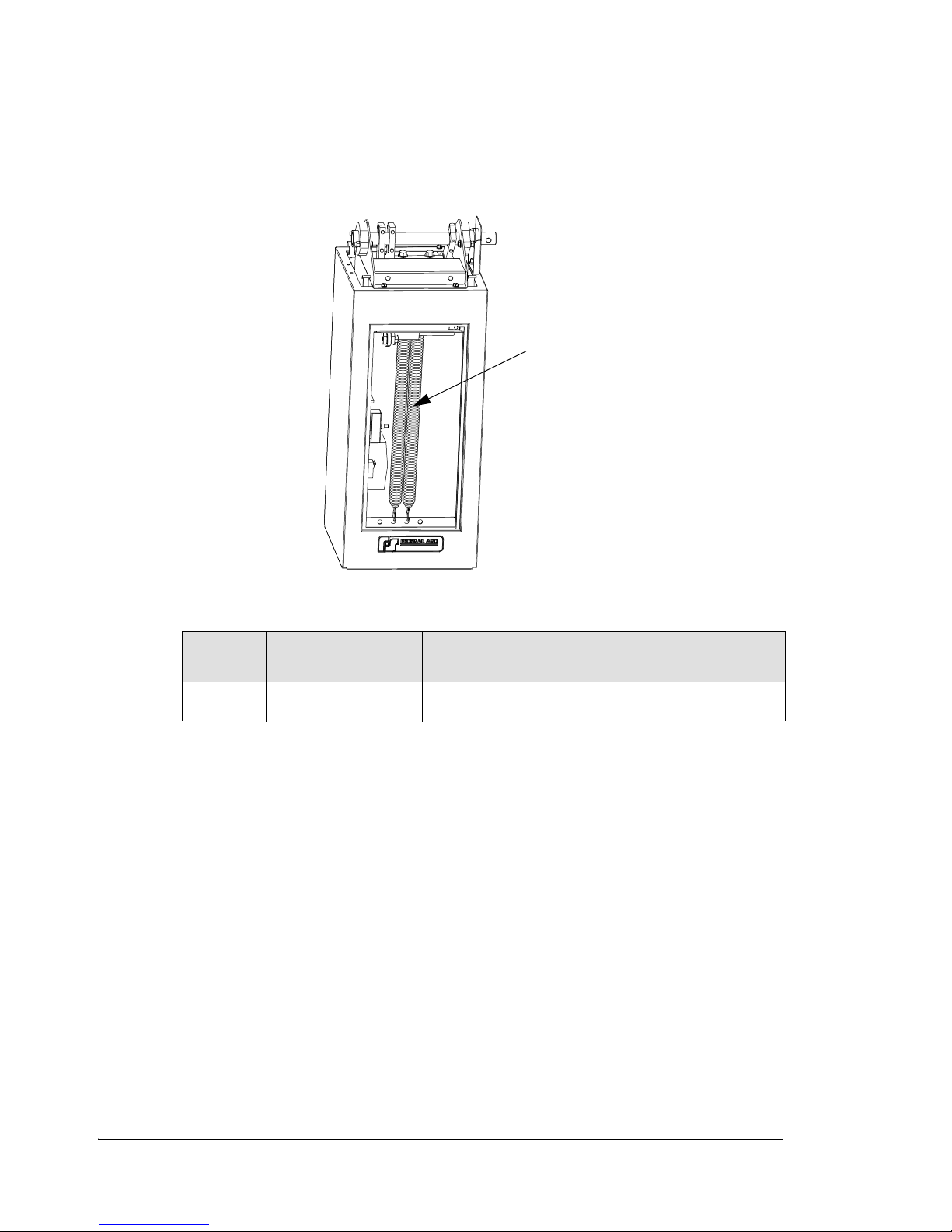
Mainsprings
1
This section identifies mainspring part numbers.
Figure B.1
Mainspring Parts
Table B-1 — Mainspring Part Numbers
No. on
Figure
1 50-25403 MAINSPRING, INDUSTRIAL GATE
Part Number Description
64 • Requesting a Repair ZMA-330, Ver.6 PosiDRIVE Security Gate
Page 73
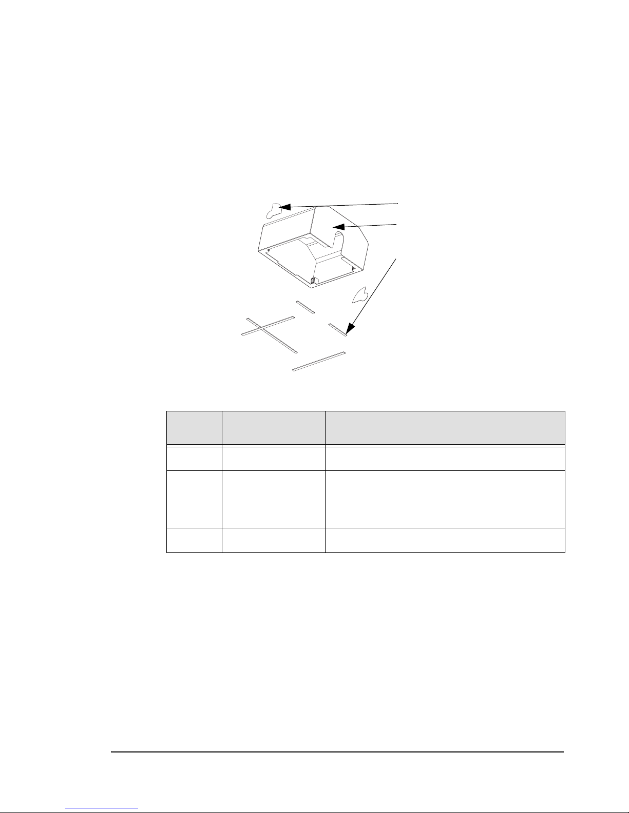
Enclosure
1
2
3
This section identifies enclosure part numbers. It includes the following illustrations:
■ Figure B.2, Enclosure Cap Parts, on page B-65
■ Figure B.3, Enclosure Door Parts, on page B-66
■ Figure B.4, Enclosure Cabinet Parts, on page B-67
Figure B.2
Enclosure Cap Parts
Table B-2 —
No. on
Figure
1 20-11945 Label, PosiDRIVE logo (2 required)
Part Number Description
Enclosure Cap Part Numbers
2 50-14021Y
50-14021W
50-14021S
Enclosure Cap, Posi Drive Yellow
Enclosure Cap, Posi Drive White
Enclosure Cap, Posi Drive Special
3 11-3226 WEATHERSTRIPPING, 1/8 X 3/8
PosiDRIVE Security Gate ZMA-330, Ver. 6 Requesting a Repair • 65
Page 74
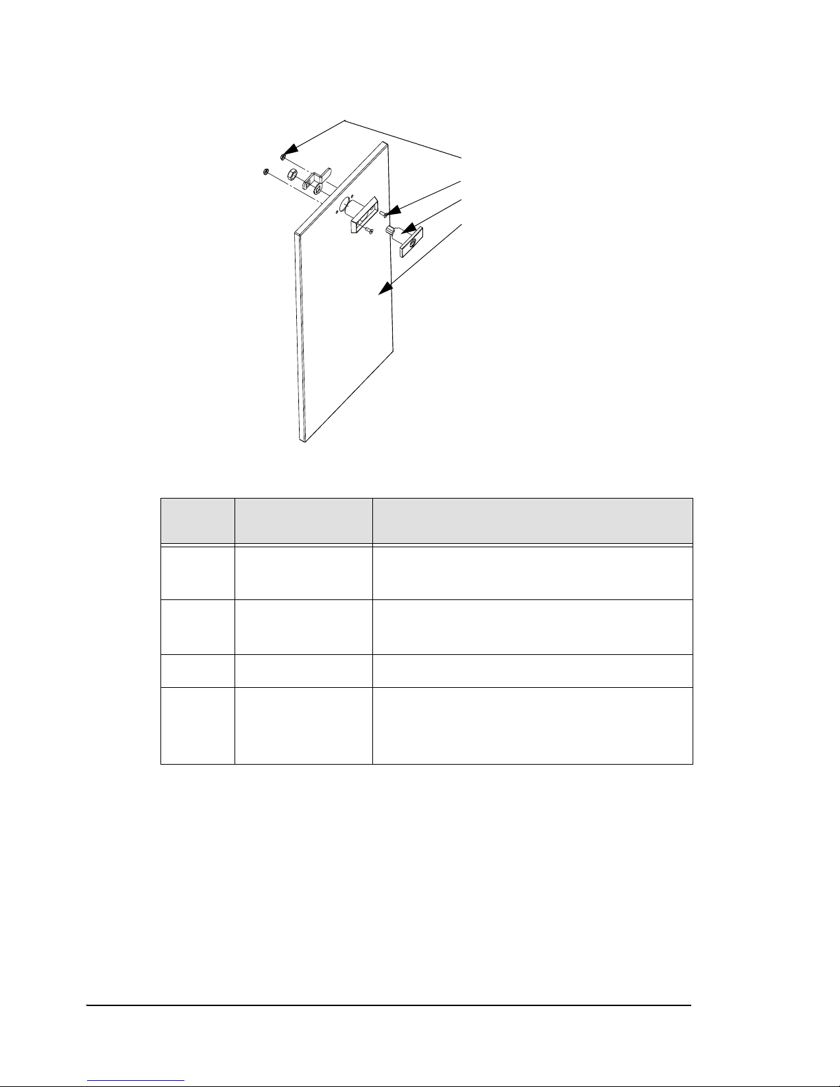
Figure B.3 Enclosure Door Parts
1
2
3
4
No. on
Figure
Table B-3 —
Part Number Description
Enclosure Door Part Numbers
1 n/a 10-24 Kep Nut (2 required)
(metric = M5 x 0.8)
2 n/a 10-24 x 1/2 Flat Head Screw (2 required)
(metric = M5 x 0.8 x 12)
3 11-0003 LOCK, T-HANDLE
4 50-14020Y
50-14020W
50-14020S
Door Enclosure, PosiDrive Yellow
Door Enclosure, Posi Drive White
Door Enclosure, Posi Drive Special
66 • Requesting a Repair ZMA-330, Ver.6 PosiDRIVE Security Gate
Page 75
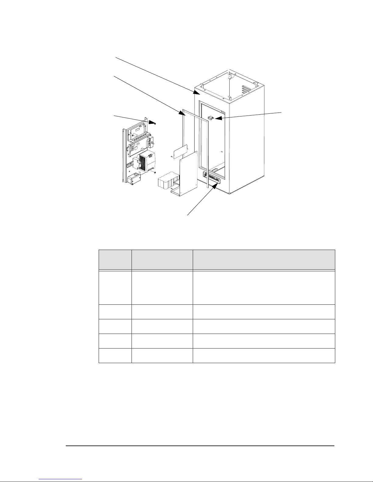
Figure B.4 Enclosure Cabinet Parts
1
2
3
4
5
Table B-4 —
No. on
Figure
1 50-14018Y
2 11-3226 WEATHERSTRIPPING, 1/8 X 3/8
3 21-11944 Switch, Pushbutton w/ cheat interlock
4 n/a 10-24 Kep Nut (4 required)
5 10-4847 NAMEPLATE, LARGE FEDERAL APD
Part Number Description
50-14018W
50-14018S
Enclosure Sub-Assembly Part Numbers
Enclosure Base, Posi Drive Yellow
Enclosure Base, Posi Drive White
Enclosure Base, Posi Drive Special
PosiDRIVE Security Gate ZMA-330, Ver. 6 Requesting a Repair • 67
Page 76
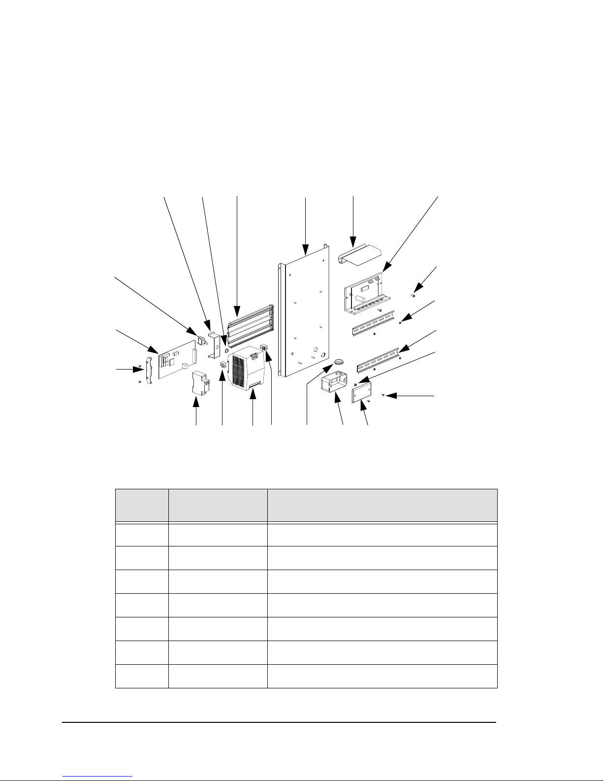
Electrical Components
15
19
18
31
6
13
4
10
5
11
7
9
8
17
16
16
2
12
20
14
This section identifies the electrical component part numbers. It includes the following
illustrations:
■ Figure B.5, Electrical Sub-Panel Parts, on page B-68
■ Figure B.6, Detector Bracket and Backup Battery Assembly Parts, on page B-70
Figure B.5
Electrical Sub-Panel Parts
Table B-5 —
No. on
Figure
68 • Requesting a Repair ZMA-330, Ver.6 PosiDRIVE Security Gate
1 20-11931 Electronics Subpanel
2 50-25799 Electronics Shield
3 21-11897 Motor Driver Board
4 See Description #10-24 x 1/2” Pan Head Screw
5 See Description #6-32 Keps Nut (small)
6 20-11912 DIN Rail (35mm)
7 See Description #6-32 Keps Nut
Part Number Description
Electrical Sub-Panel Part Numbers
Page 77
Table B-5 — Electrical Sub-Panel Part Numbers (Continued)
No. on
Figure
8 See Description #6-32 x 3/8” Flat Head Screw
9 11-0700 Handy-Box Cover
10 11-0699 Handy-Box Duplex
11 11-3343 Grommet
12 21-11947 Fastener, Power Supply, Right Hand
13 21-11927 Power Supply, Industrial Gate
14 21-11947-2 Fastener, Power Supply, Right Hand
15 21-11929 Circuit Breaker, 5 AMP 2 Pole Time Delay
16 21-11946 PC Board Holder, DIN Rail Mtd.
17 22-10345 PC Board Assembly, Industrial Gate
18 11-1099 Switch, SPDT
Part Number Description
19 20-11932 Switch Bracket, Raise/Lower
20 11-1099nut Switch Nut
PosiDRIVE Security Gate ZMA-330, Ver. 6 Requesting a Repair • 69
Page 78
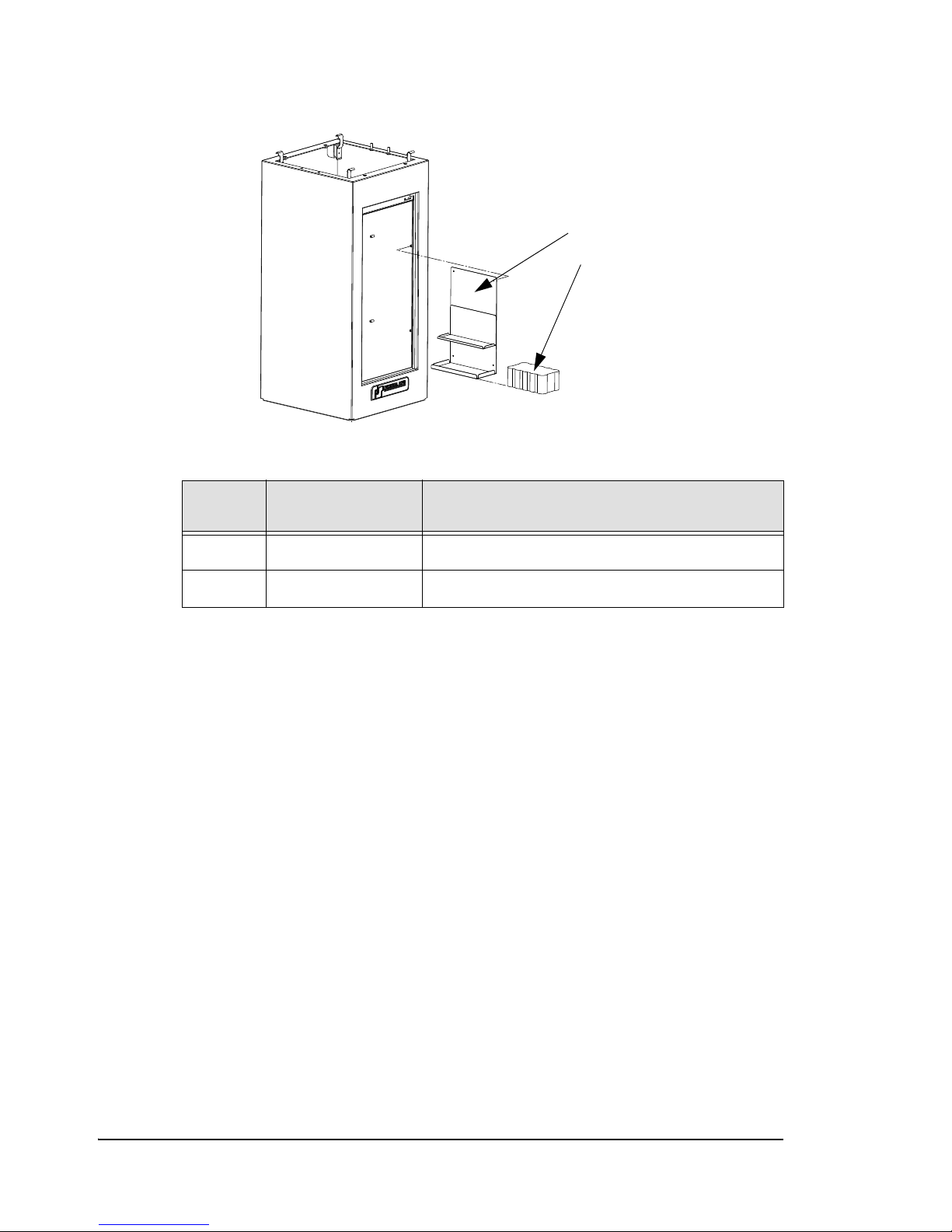
Figure B.6 Detector Bracket and Backup Battery Assembly Parts
1
2
Table B-6 —
No. on
Figure
Part Number Description
Detector Bracket and Backup Battery Assembly Part Numbers
1 20-11999 DETECTOR BRACKET, PosiDRIVE GATE
2 21-11935 BATTERY BACKUP ASSY, PosiDRIVE GATE
Standard Gate Arm
You can purchase:
■ “Individual Components” on page B-71
■ “Gate Arm Assemblies” on page B-72
■ “Gate Arm Packages” on page B-72
70 • Requesting a Repair ZMA-330, Ver.6 PosiDRIVE Security Gate
Page 79
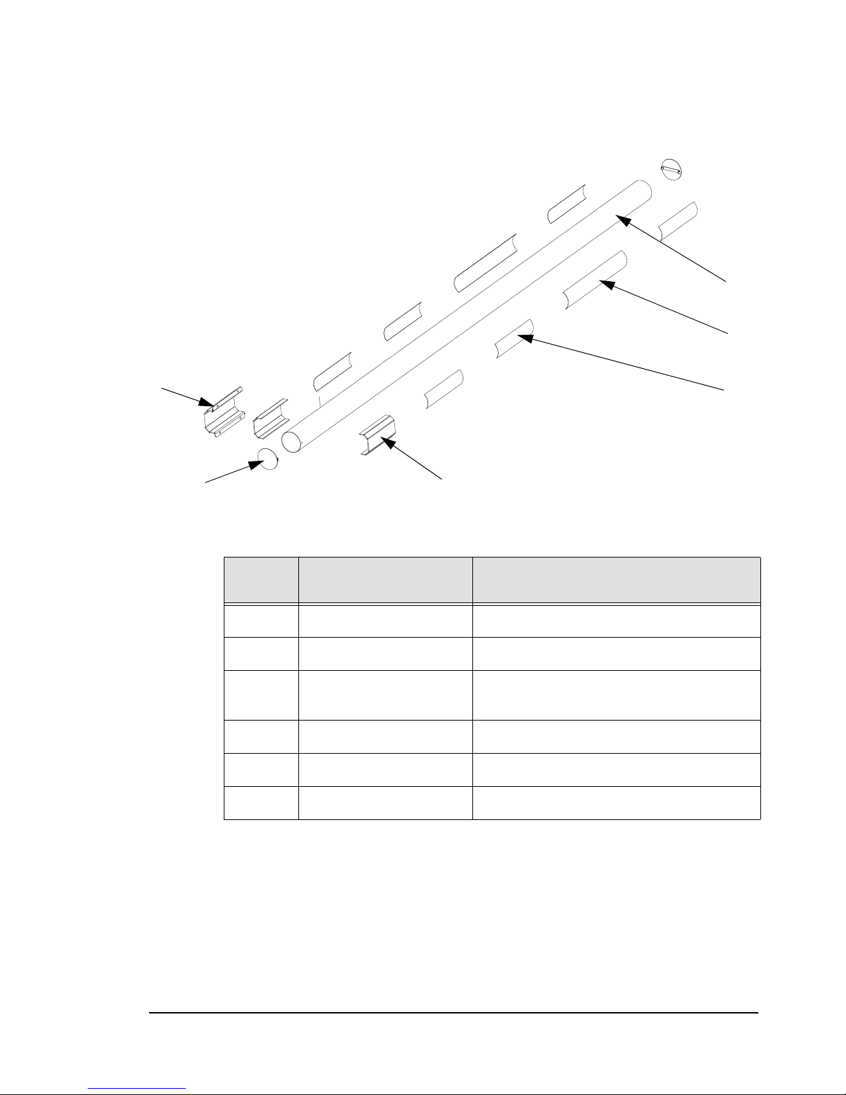
Individual Components
5
4
3
2
1
6
Figure B.7
Standard Gate Arm Parts
Table B-7 —
No. on
Figure
1 50-25463 Gate Arm, Round
2 20-12186 Reflective Tape
3 50-14048 Label, Gate Arm PosiDRIVE Caution,
4 51-26545 Plastic End Cap
5 50-25099 Arm Clamp
6 50-25102 Anti-slip Insert
Part Number Description
Standard Gate Arm Individual Part Numbers
Symbols
PosiDRIVE Security Gate ZMA-330, Ver. 6 Requesting a Repair • 71
Page 80

Gate Arm Assemblies
Gate Arm Assembly includes all gate arm parts. Gate Arm Assembly part numbers are:
■ 10 ft: 53-14065
■ 12 ft: 53-14066
■ 14 ft: 53-14067
■ 16 ft: 53-14068
■ 18 ft: 53-14069
■ 20 ft: 53-14070
Gate Arm Packages
Gate Arm Packages includes all gate arm parts and mainsprings. Gate Arm Package part
numbers are:
■ 10 ft: 53-14059
■ 12 ft: 53-14060
■ 14 ft: 53-14062
■ 16 ft: 53-14063
■ 18 ft: 53-14063
■ 20 ft: 53-14064
72 • Requesting a Repair ZMA-330, Ver.6 PosiDRIVE Security Gate
Page 81
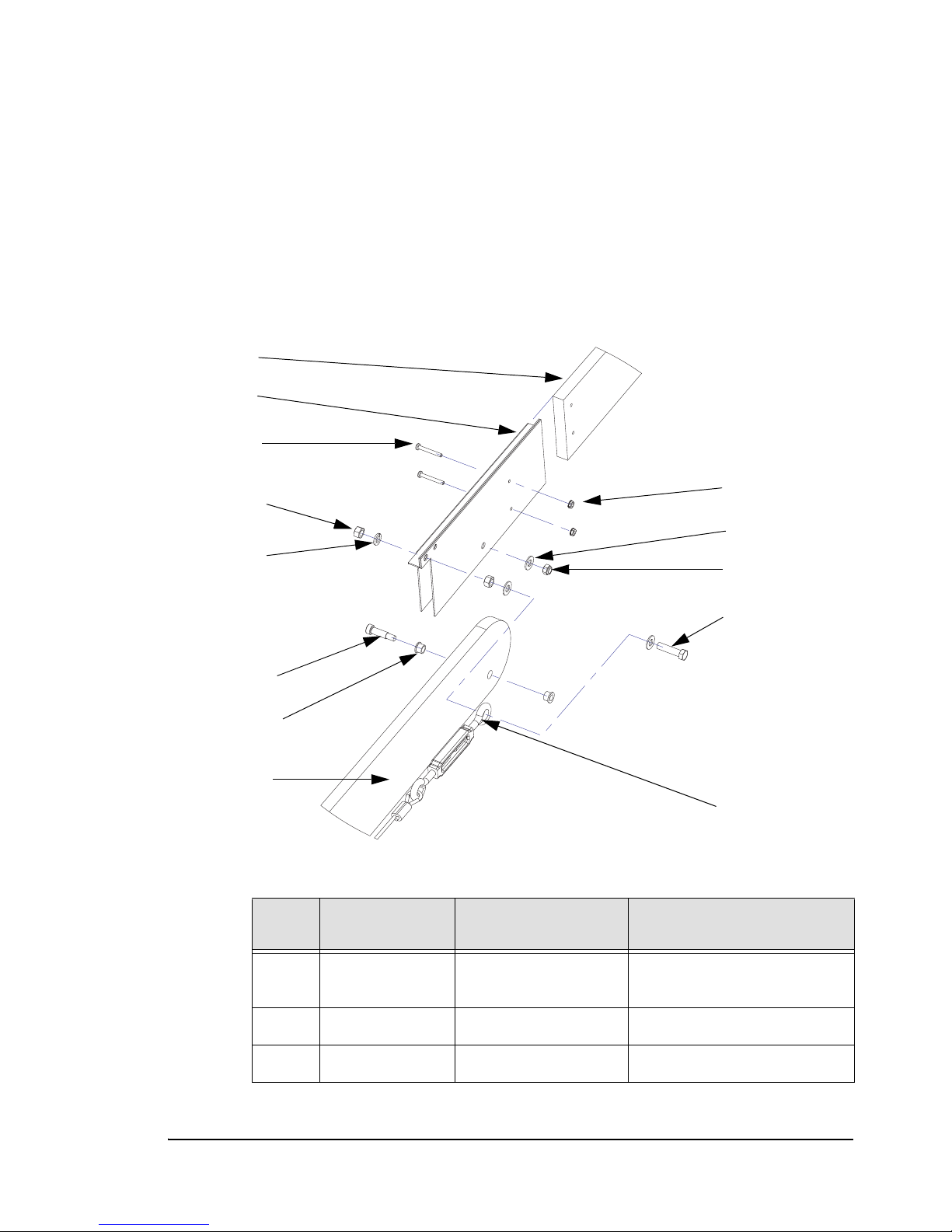
Folding Gate Arm
1
2
3
4
5
6
7
8
9
10
11
12
13
This section shows the part numbers for the folding gate arm components and for the
folding gate arm packages. It includes the following illustrations:
■ Figure B.8, Folding Gate Arm and Stabilizer Parts, on page B-73
■ Figure B.9, Folding Gate Arm Cable Tower Parts, on page B-75
■ Figure B.10, Folding Gate Arm Adapter and Fixed Section Parts, on page B-76
■ Figure B.11, Folding Gate Arm Packages, on page B-77
Figure B.8
Folding Gate Arm and Stabilizer Parts
No. on
Figure
1 1 20-4828 Gate Arm, 10 ft. Tapered,
2 1 20-0051 Gate Arm Stabilizer
PosiDRIVE Security Gate ZMA-330, Ver. 6 Requesting a Repair • 73
3 2 See Description #10-24 x 1.50 Pan Head Screw
Table B-8 — Folding Gate Arm with Stabilizer Part Numbers
Qty. Part Number Description
Folding Section
Page 82
Table B-8 — Folding Gate Arm with Stabilizer Part Numbers (Continued)
No. on
Figure
4 3 See Description 3/8 - 16 UNC Hex Nut
5 17 See Description 3/8" Lock Washer
6 1 See Description 0.375 x 1.00 Shoulder Screw
7 2 20-0056 Bushing, 3/8"
8 1 20-4828 Gate Arm, 10 ft. Tapered,
9 8 See Description #10 - 24 Keps Nut Zinc Plated
10 20 See Description 3/8” Plain Washer
11 3 See Description 5/16 - 18 UNC Nylock Hex Nut
12 7 See Description 3/8 - 16 UNC x 1.50" Hex Bolt
13 1 11-4127 3" Turnbuckle
Qty. Part Number Description
Fixed Section
Steel
74 • Requesting a Repair ZMA-330, Ver.6 PosiDRIVE Security Gate
Page 83
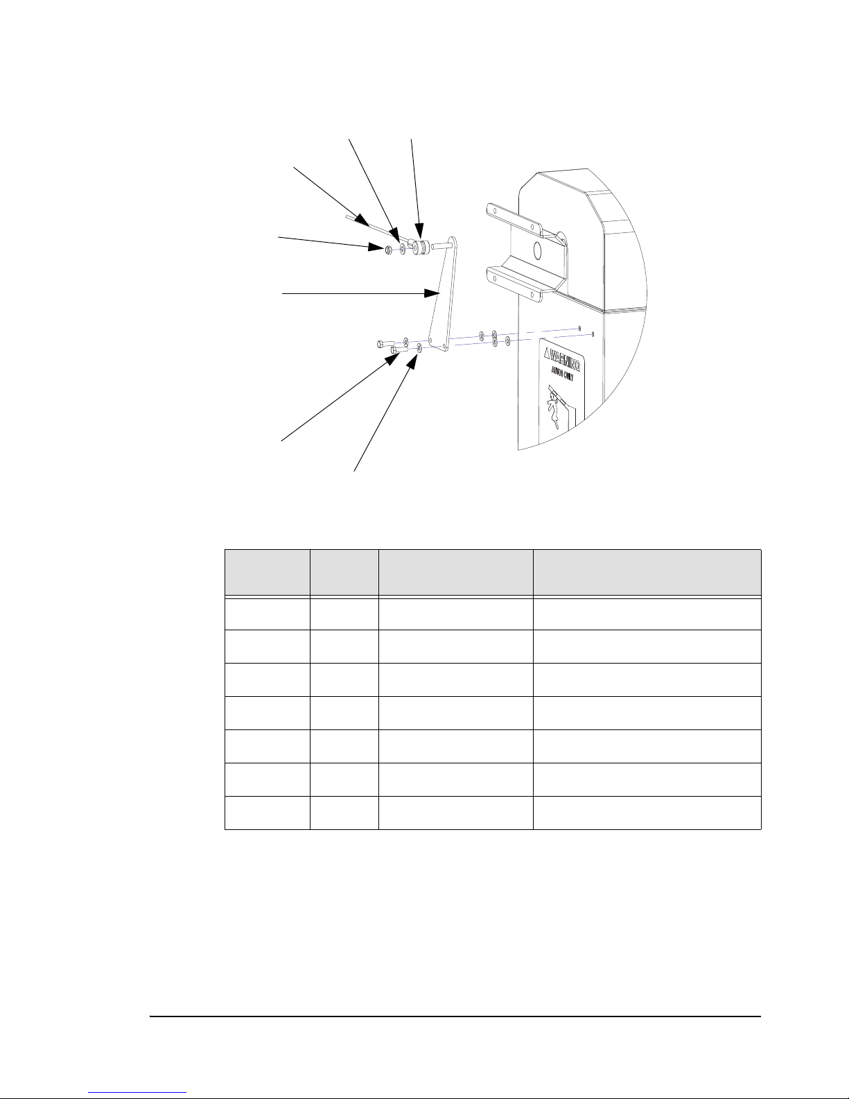
Figure B.9 Folding Gate Arm Cable Tower Parts
1
3
2
4
5
6
7
Table B-9 — Folding Gate Arm Cable Tower Part Numbers
No. on
Figure
1 1 20-3332 Spacer, Folding Arm Cable
2 20 See Description 3/8” Plain Washer
3 3.87’ 11-3335 Cable, 3/18" DIA Steel
4 3 See Description 3/8 - 16 UNC Hex Nut
5 1 50-14076 Cable Tower
6 10 See Description 5/16 - 18 UNC x 1” Hex Bolt
7 18 See Description 5/16" Plain Washer
Qty. Part Number Description
PosiDRIVE Security Gate ZMA-330, Ver. 6 Requesting a Repair • 75
Page 84
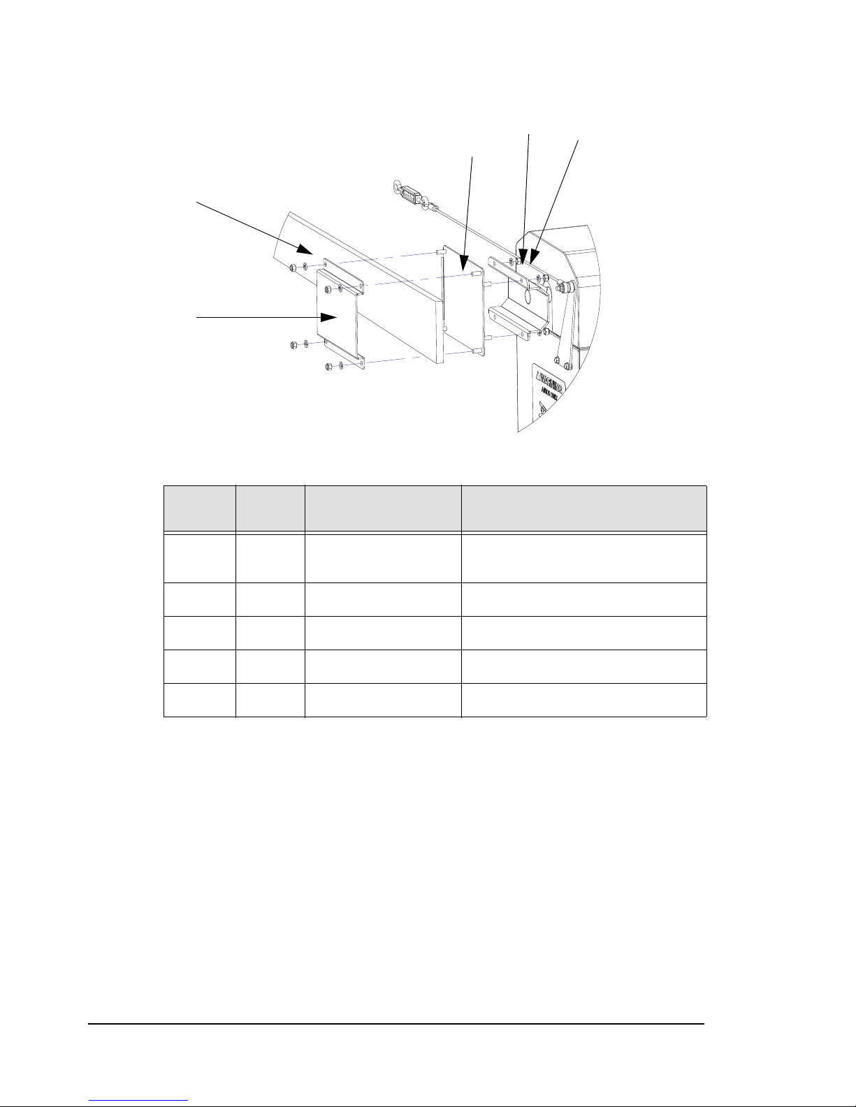
Figure B.10 Folding Gate Arm Adapter and Fixed Section Parts
1
2
3
4
5
Table B-10 — Folding Gate Arm Adapter and Fixed Section Part Numbers
No. on
Figure
Qty. Part Number Description
1 16 See Description 3/8 - 16 UNC Hex Nut Zinc Plated
Steel
2 17 See Description 3/8" Lock Washer
3 1 50-14074 Adapter, Folding Arm
4 1 20-4828 Gate Arm 10 ft. Fixed Section
5 1 50-14075 Arm Retainer
76 • Requesting a Repair ZMA-330, Ver.6 PosiDRIVE Security Gate
Page 85
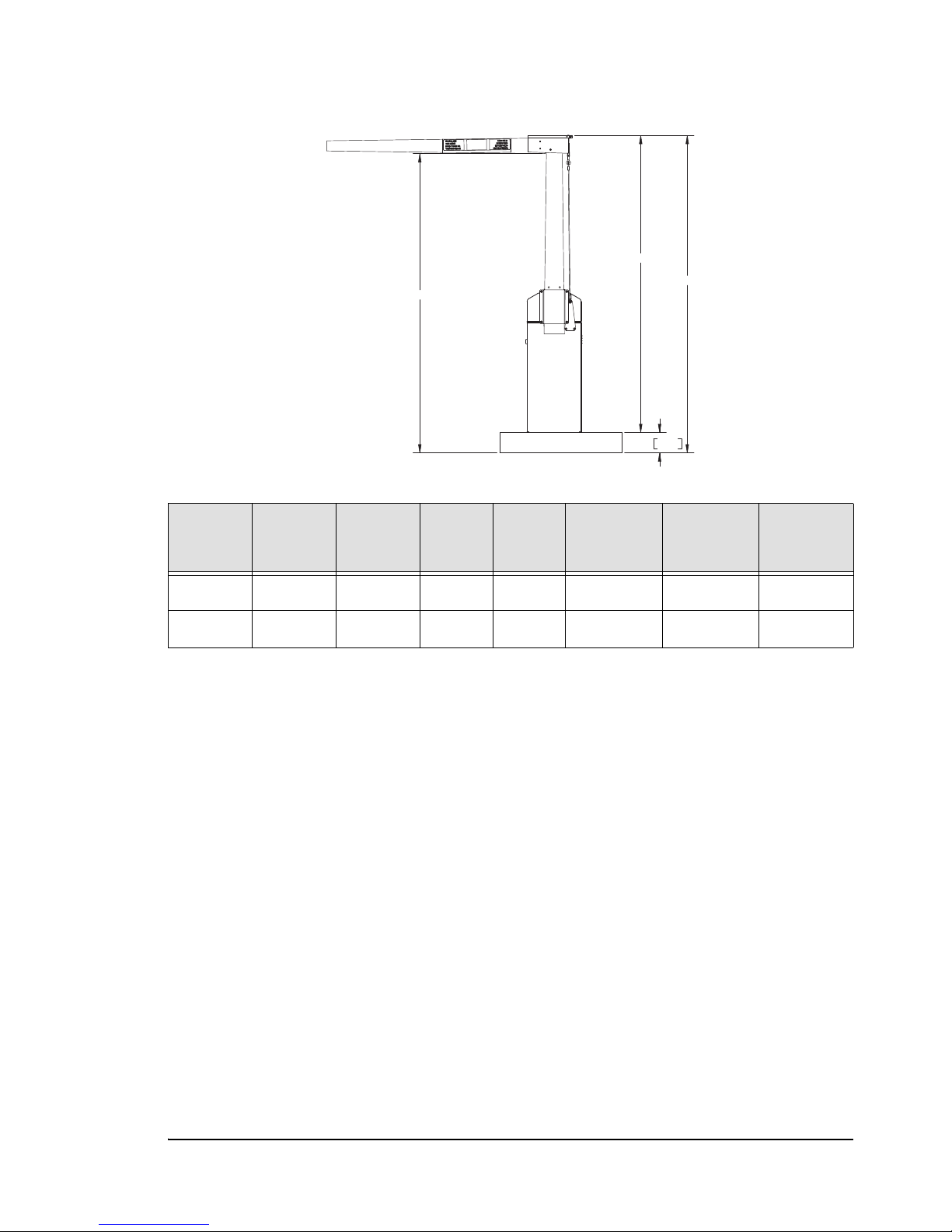
Figure B.11 Folding Gate Arm Packages
5
D4
D3
6.00 152.4
D
Type
Left
Hand
Part #
Right
Hand
Part #
Arm
Length
Cable
Length
Vehicle
Clearance
Clearance
from Curb
Clearance
from
Roadway
Std. 53-14078 53-14084 55-3/4” 40-1/2” 7’-4” 7’-3” 7’-9”
ADA 53-14085 53-14086 70-3/4” 55-1/2” 8’-8” 8’-7” 9’-1”
PosiDRIVE Security Gate ZMA-330, Ver. 6 Requesting a Repair • 77
Page 86
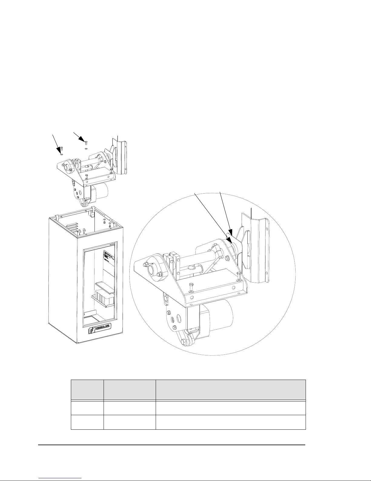
Drive Mechanism
1
4
2
3
This section identifies the drive mechanism component part numbers. It includes the
following illustrations:
■ Figure B.12, Drive Mechanism Installation Parts, on page B-78
■ Figure B.13, Drive Mechanism Frame Parts (View 1), on page B-79
■ Figure B.14, Drive Mechanism Parts (View 2), on page B-80
Figure B.12
Drive Mechanism Installation Parts
Table B-11 —
No. on
Figure
1 n/a 5/16 Lock Washer (4 required)
2 n/a 5/16-18 x 3/4 Hex Head Cap Screw (4 required)
78 • Requesting a Repair ZMA-330, Ver.6 PosiDRIVE Security Gate
Part Number Description
Drive Mechanism Installation Parts
Page 87
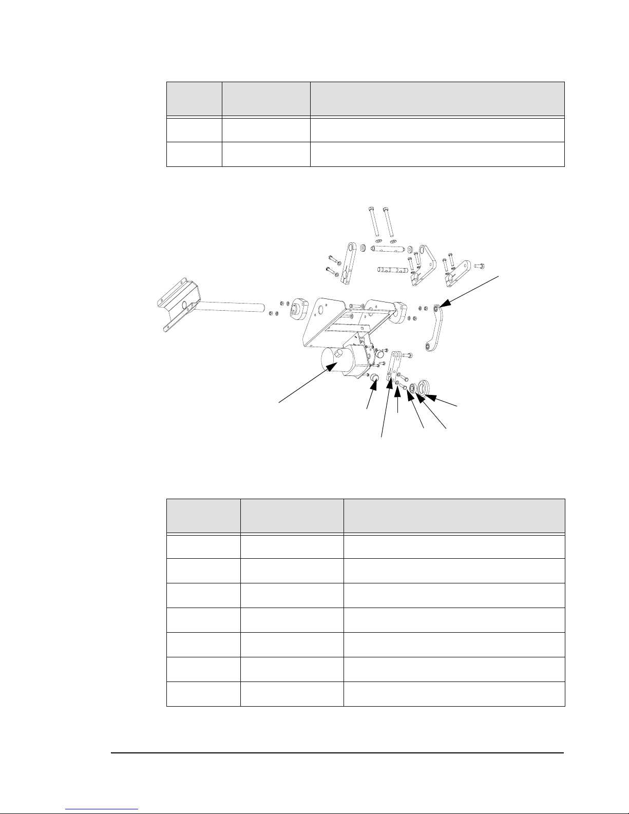
Table B-11 — Drive Mechanism Installation Parts (Continued)
1
5
4
2
3
6
7
8
No. on
Figure
3 20-11914 SEAL, MAIN SHAFT INDUSTRIAL GATE
4 20-11913 SIDE SHIELD, MAINSHAFT INDUSTRIAL GATE
Part Number Description
Figure B.13 Drive Mechanism Frame Parts (View 1)
No. on
Figure
1 21-11908 Bump Stop
2 See Description 3/8” Lock Washer
3 20-11905 Motor Bearing Support
4 21-11906 Bearing, Motor Support
5 21-11896 Motor
6 20-11907 Motor Crank
7 See Description 3/8-16 UNC x 1.50” Hex Bolt
PosiDRIVE Security Gate ZMA-330, Ver. 6 Requesting a Repair • 79
Table B-12 — Drive Mechanism Frame (View 1) Part Numbers
Part Number Description
Page 88
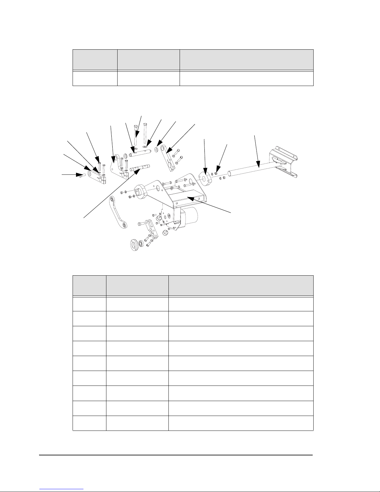
Table B-12 — Drive Mechanism Frame (View 1) Part Numbers (Continued)
1
2
3
4
5
6
7
8
9
10
11
12
13
14
15
No. on
Figure
8 50-26748 Connecting Rod
Part Number Description
Figure B.14 Drive Mechanism Parts (View 2)
Table B-13 — Drive Mechanism (View 2) Part Numbers
No. on
Figure
1 20-11918 Mechanism Frame
2 21-11901 Bearing Main Shaft
3 See Description 3/8” Lock Washer
4 See Description 3/8” Hex Nut
5 See Description 1/2-13 x 1-1/4 Hex Bolt
6 50-25566 Mainshaft Crank Part 1, Steel
7 See Description 3/8-16 UNC x 2” Hex Bolt
8 50-25567 Mainshaft Crank Part 2, Steel
9 21-11921 Bearing, Spring Crank
Part Number Description
80 • Requesting a Repair ZMA-330, Ver.6 PosiDRIVE Security Gate
Page 89
Table B-13 — Drive Mechanism (View 2) Part Numbers (Continued)
No. on
Figure
10 20-11922 Mainspring Pivot Bar
11 See Description 1/2” Plain Washer, Zinc Plated
12 See Description 1/2-13 x 5 Hex Bolt
13 20-11923 Mainspring Connection Bar
14 20-11920 Spring Crank
15 50-25098 Mainshaft
Part Number Description
PosiDRIVE Security Gate ZMA-330, Ver. 6 Requesting a Repair • 81
Page 90

82 • Requesting a Repair ZMA-330, Ver.6 PosiDRIVE Security Gate
Page 91

Index
A
AC mains .............................................................11
auto/manual switch ..............................................12
automatic operation ...............................................2
auto-raise, enabling..............................................44
B
backout detection, enabling .................................44
backout time, setting............................................43
backup battery......................................................10
part number...................................................70
battery, backup.....................................................10
C
cabinet
components.....................................................6
description of ..................................................6
installing .......................................................20
footprint dimensions..............................21
opening .........................................................16
part numbers .................................................67
removing cap ................................................17
cable tower...........................................................29
cap, enclosure
part numbers .................................................65
removing.......................................................17
circuit breaker switch
description of ................................................12
part number...................................................69
components
electrical, description of ...............................10
mechanical, description of..............................7
connecting rod
description of ..................................................9
greasing bearings ..........................................47
controller..............................................................12
inputs ............................................................15
outputs ..........................................................16
overview .......................................................14
D
dimensions
enclosure installation, for .............................21
folding gate arm............................................77
DIP switches
overview .......................................................15
setting ...........................................................42
door safety switch................................................12
draw latch.............................................................17
drive mechanism
aligning .........................................................54
frame...............................................................8
part numbers ..........................................80
installation
part numbers ..........................................78
overview .......................................................10
part numbers .................................................78
E
electrical components ..........................................10
description of ................................................10
electrical sub-panel ..............................................12
illustration of.................................................11
part numbers .................................................68
enclosure
components.....................................................6
description of ..................................................6
installing .......................................................20
footprint dimensions..............................21
opening .........................................................16
part numbers .................................................67
removing cap ................................................17
enclosure cap
part numbers .................................................65
enclosure door
part numbers .................................................66
F
flange, gate arm......................................................9
folding gate arm
cable tower....................................................29
dimensions ....................................................77
overview .......................................................13
part numbers .................................................73
free mode ...............................................................3
G
gate arm
advancing manually......................................49
aligning drive mechanism.............................54
changing configuration .................................34
defining length..............................................43
dimensions for folding arm...........................77
disabling lock-down feature .........................40
flange ..............................................................9
folding gate arm
overview ................................................13
part numbers ..........................................73
PosiDRIVE Security Gate ZMA-330, Ver. 6 Index • 83
Page 92

installing .......................................................25
folding gate arm ....................................27
standard gate arm ..................................26
locking ..........................................................49
lowering........................................................49
part numbers .................................................70
raising ...........................................................49
standard gate arm
overview ................................................13
part numbers..........................................71
unlocking ......................................................49
Gate Up output.....................................................16
H
handy-box ............................................................11
help ......................................................................58
I
inputs....................................................................15
installation
changing gate arm configuration ..................34
disabling lock-down feature .........................40
enclosure.......................................................20
installing the gate arm ..................................25
folding gate arm ....................................27
standard gate arm ..................................26
overview .......................................................20
setting DIP switches .....................................42
setting mainsprings.......................................38
wiring the gate ..............................................23
J
junction box .........................................................11
part number...................................................69
L
locked down feature.............................................40
Loop A input........................................................ 15
Loop B input ........................................................15
M
main power feed ..................................................11
mainshaft
bearings...........................................................9
crank ...............................................................9
description of ..................................................9
mainshaft bearings, greasing ...............................47
mainspring
adjustment bolts..............................................9
connection bar ................................................9
crank ...............................................................9
installing .......................................................52
pivot bar..........................................................9
setting............................................................38
mainsprings
adding ...........................................................52
description of ..................................................7
part numbers .................................................64
removing.......................................................52
replacing .......................................................52
setting............................................................38
maintenance, preventive ......................................46
manual operation....................................................2
manual/auto switch ..............................................12
mechanical components.........................................7
description of ..................................................7
modes
free mode ........................................................3
pay mode.........................................................4
pay/free mode .................................................5
motor................................................................7, 10
crank ...............................................................9
description of ..................................................9
power ............................................................12
motor driver board ...............................................12
part number...................................................68
O
operation
automatic ........................................................2
free mode.................................................3
pay mode .................................................4
pay/free mode ..........................................5
during power failure .......................................6
manual ............................................................2
operational overview..............................................2
optimum operating temperature.............................2
orders
how to place..................................................62
outputs..................................................................16
overview
installation ....................................................20
operational ......................................................2
structural .........................................................6
P
part numbers
drive mechanism...........................................78
electrical sub-panel .......................................68
enclosure.......................................................67
enclosure cap ................................................65
enclosure door...............................................66
folding gate arm............................................73
mainsprings...................................................64
standard gate arm..........................................71
84 • Index ZMA-330, Ver.6 PosiDRIVE Security Gate
Page 93

pay mode................................................................4
pay/free mode ........................................................5
PosiDRIVE controller..........................................12
inputs ............................................................15
outputs ..........................................................16
overview .......................................................14
power failure
backup battery ..............................................10
detection .........................................................6
enabling auto-raise feature ...........................44
gate operation, during.....................................6
power receptacle
wiring illustration .........................................23
power supply..................................................10, 13
part number...................................................69
preventive maintenance .......................................46
problems, resolving..............................................48
R
Raise/Lower input................................................15
repair
requesting .....................................................62
Reset switch.........................................................14
right-/left-hand configuration ..............................34
S
safety switch ........................................................12
sinusoidal mechanism............................................7
SRO .....................................................................62
structural overview ................................................6
System Fault output .............................................16
T
technical support..................................................58
temperature, optimum............................................2
troubleshooting ....................................................48
V
vend counts, enabling ..........................................42
Vend input ...........................................................15
W
warning label, gate arm........................................27
wiring.............................................................23, 24
power receptacle...........................................23
PosiDRIVE Security Gate ZMA-330, Ver. 6 Index • 85
Page 94

86 • Index ZMA-330, Ver.6 PosiDRIVE Security Gate
Page 95

Page 96

For Sales and Service, Contact Your Local Federal APD Distributor:
42775 Nine Mile Road • Novi, Michigan 48375 • USA
Tel: (248) 374-9600• Fax : (248) 374-9610
USA Toll Free: (800) 521-9330 • CN Toll Free: (800) 331-9144
www.FederalAPD.com
© Federal APD, Inc. The features described in this manual may not be included with every model, and Federal APD reserves the right to modify its products and
supporting documentation without notice.
 Loading...