

Federal LPRSS Series, ELPRSS Series, LPRSS3, LPRSS4, LPRSS5 Installation & Operation Instructions
...
E2915-3 Rev. A 09/01/2018
Installation & Operation Instructions
Refrigerated LPRSS & ELPRSS Models
Federal Industries
215 Federal AVE
Belleville, WI 53508
Toll Free: (800) 356-4206
WI Phone: (608) 424-3331
Fax: (608) 424-3234

Page 2 of 40
Contents
(1) Introduction ..................................................................................................................................... 4
1.1 Serial Number ............................................................................................................................... 4
(2) Warning Labels & Safety Instructions .............................................................................................. 5
(3) Pre-Installation Procedures ............................................................................................................. 6
3.1 Inspection for Shipping Damage .................................................................................................. 6
(4) General Electrical & Grounding ....................................................................................................... 7
4.1 Cord Connected ............................................................................................................................ 7
4.2 Permanent Connected (Option) ................................................................................................... 7
(5) Installation Instructions ................................................................................................................... 8
5.1 Locating the Display Case ............................................................................................................. 8
5.2 Removing Case From Shipping Skid and General Installation ..................................................... 8
5.3 Cleaning ........................................................................................................................................ 8
5.4 Center Panel Joining (Option) ...................................................................................................... 8
5.5 Refrigeration System .................................................................................................................. 10
5.5.1 Self Contained Models ............................................................................................................ 10
5.5.2 Remote Models ...................................................................................................................... 10
5.6 Evaporator Condensate Drain Tube ........................................................................................... 10
5.7 Condensate Pump ...................................................................................................................... 11
(6) Shelving Installation & Removal .................................................................................................... 13
6.1 Metal Shelves ............................................................................................................................. 13
6.2 Glass Shelves .............................................................................................................................. 14
6.3 Optional Shelf Lights (ELPRSS) .................................................................................................... 15
(7) Plastic End Removal & Installation ................................................................................................ 16
(8) Rear Doors (Options) ..................................................................................................................... 17
(9) Night Curtain .................................................................................................................................. 18
(10) Security Night Curtain (Option) ..................................................................................................... 19
(11) Operating Instructions ................................................................................................................... 20
11.1 User Controls Overview ............................................................................................................. 20
11.2 Using the electronic control ....................................................................................................... 21
11.2.1 Button and Display Overview ................................................................................................. 21
11.2.2 Powering on control ............................................................................................................... 21
11.2.3 Adjusting the set point ........................................................................................................... 22
11.2.4 Entering manual defrost mode............................................................................................... 22
11.2.5 Error codes .............................................................................................................................. 22
11.3 Initial Startup .............................................................................................................................. 23
11.4 Placing Product in Case .............................................................................................................. 24
(12) Maintenance .................................................................................................................................. 26
12.1 Light Replacement ...................................................................................................................... 26
(13) Periodic Maintenance .................................................................................................................... 27
13.1 Cleaning Condenser Coil............................................................................................................. 27

Page 3 of 40
(14) Cleaning Instructions ..................................................................................................................... 28
14.1 Daily Cleaning ............................................................................................................................. 28
14.2 Weekly Cleaning ......................................................................................................................... 28
(15) Sale & Disposal ............................................................................................................................... 31
15.1 Owner Responsibility ................................................................................................................. 31
(16) Service Information ........................................................................................................................ 32
16.1 Pre-Service checklist ................................................................................................................... 32
16.1.1 Case does not operate ............................................................................................................ 32
16.1.2 Lights do not operate ............................................................................................................. 32
16.1.3 Case temperature too warm (product is exceeding 41°F) ..................................................... 32
16.2 Special Service Instructions ........................................................................................................ 33
16.3 Refrigeration & Electrical Data ................................................................................................... 33
16.4 Electronic Control Operation ..................................................................................................... 33
16.4.1 Operation ................................................................................................................................ 33
16.4.2 Defrost Cycle ........................................................................................................................... 34
16.5 Control Parameters .................................................................................................................... 34
16.6 Error Codes ................................................................................................................................. 34
16.7 Refrigeration Operation ............................................................................................................. 35
16.7.1 Self Contained Models ............................................................................................................ 35
16.7.2 Remote Models ...................................................................................................................... 35
(17) Wiring Diagrams ............................................................................................................................. 37
17.1 Self Contained ............................................................................................................................ 37
17.2 Remote ....................................................................................................................................... 37
(18) Replacement Parts ......................................................................................................................... 38
Tables
Table 1- Shelf Loading Limits .................................................................................................................... 24
Table 2 - Electrical Ratings ........................................................................................................................ 33
Table 3 - Control Parameters .................................................................................................................... 34
Table 4 - Error Codes and Resolutions ...................................................................................................... 34
Table 5 - Temperature Probe Common Resistance Chart ........................................................................ 35

Page 4 of 40
(1) INTRODUCTION
Thank you for purchasing a Federal Industries display case. This manual contains important instructions for
installing and servicing the LPRSS refrigerated self-service merchandisers. A repair parts list and wiring diagram
are also included in the manual. Read all of these documents carefully before installing or servicing your case.
NOTICE
Read this manual before installing your case. Keep this manual and refer to it
before doing any service on the equipment. Failure to do so could result in
personal injury or damage to the case.
NOTICE
Installation and service of the electrical components in the case must be
performed by a licensed electrician.
The portions of this manual covering components contain technical instructions
intended only for persons qualified to perform electrical work.
DANGER
Improper or faulty hookup of electrical components in the case can result in
severe injury or death.
All electrical wiring hookups must be done in accordance with all applicable local,
regional, or national standards.
1.1 SERIAL NUMBER
Record the model and serial numbers of the case for easy reference. Always refer to both model and serial
numbers in your correspondence with Federal regarding the case.
Case Model__________________________ Serial Number______________________
Condensing Unit Model________________ Serial Number______________________
This manual cannot cover every installation, use, or service situation. If you need additional information, call
or write us:
WARRANTY/TECHNICAL SERVICE DEPARTMENT
Federal Industries
215 Federal AVE
Belleville, WI 53508
Toll Free (800) 356-4206 / WI Phone (608) 424-3331
Page 5 of 40
(2) WARNING LABELS & SAFETY INSTRUCTIONS
This is the safety-alert symbol. When you see this symbol on your case or in the
manual, be alert to the potential for personal injury or damage to your
equipment.
Be sure you understand all safety messages and always follow recommended precautions and safe operating
procedures.
NOTICE TO EMPLOYERS:
You must make sure that everyone who installs, uses, or services your case is
thoroughly familiar with all safety information and procedures.
Important safety information is presented in this section and throughout the manual. The following signal
words are used in the warning and safety messages:
DANGER:
Severe injury or death will occur if you ignore the message.
WARNING:
Severe injury or death can occur if you ignore the message.
CAUTION:
Minor injury or damage to your case can occur if you ignore the message.
NOTICE:
This is important installation, operation, or service information. If you ignore the
message, you may damage your case.
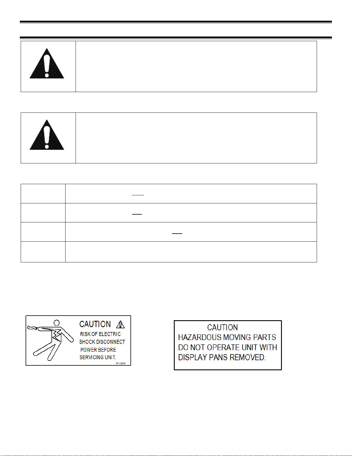
The warning and safety labels shown throughout this manual are placed on your Federal Industries case at the
factory. Follow all warning label instructions. If any warning or safety labels become lost or damaged, call our
customer service department at (800) 356-4206 for replacements.
This label is located on the back of the display
case
This label is located below the display pan.

Page 6 of 40
(3) PRE-INSTALLATION PROCEDURES
3.1 INSPECTION FOR SHIPPING DAMAGE
You are responsible for filing all freight claims with the delivering truck line. Inspect all cartons and crates for
damage as soon as they arrive. If damage is noted to shipping crates, cartons, or if a shortage is found, note
this on the bill of lading (all copies) prior to signing.
If damage is discovered when the case is uncrated, immediately call the delivering truck line and follow up the
call with a written report indicating concealed damage to your shipment. Ask for an immediate inspection of
your concealed damage item. Crating material must be retained to show the inspector from the truck line.

Page 7 of 40
(4) GENERAL ELECTRICAL & GROUNDING
DANGER:
Improper or faulty hookup of electrical components in the display case can result
in severe injury or death.
4.1 CORD CONNECTED
All standard models are supplied with a power cord that is properly sized to the amperage
requirements of the case. See the electrical data plate located on the rear left interior of the case for
the proper circuit size for each case.
The cord is factory installed protruding from the bottom rear corner of the case.
A separate circuit for each display case is required to prevent other appliances on the same circuit from
overloading the circuit and causing malfunction.
4.2 PERMANENT CONNECTED (OPTION)
Only a licensed electrician must perform all case electrical connections.
All electrical wiring hookups must be done in accordance with all applicable local, regional, or national
electrical standards.
A separate circuit for each display case is required to prevent other appliances on the same circuit from
overloading the circuit and causing malfunction.
The electrical service must be grounded upon installation.
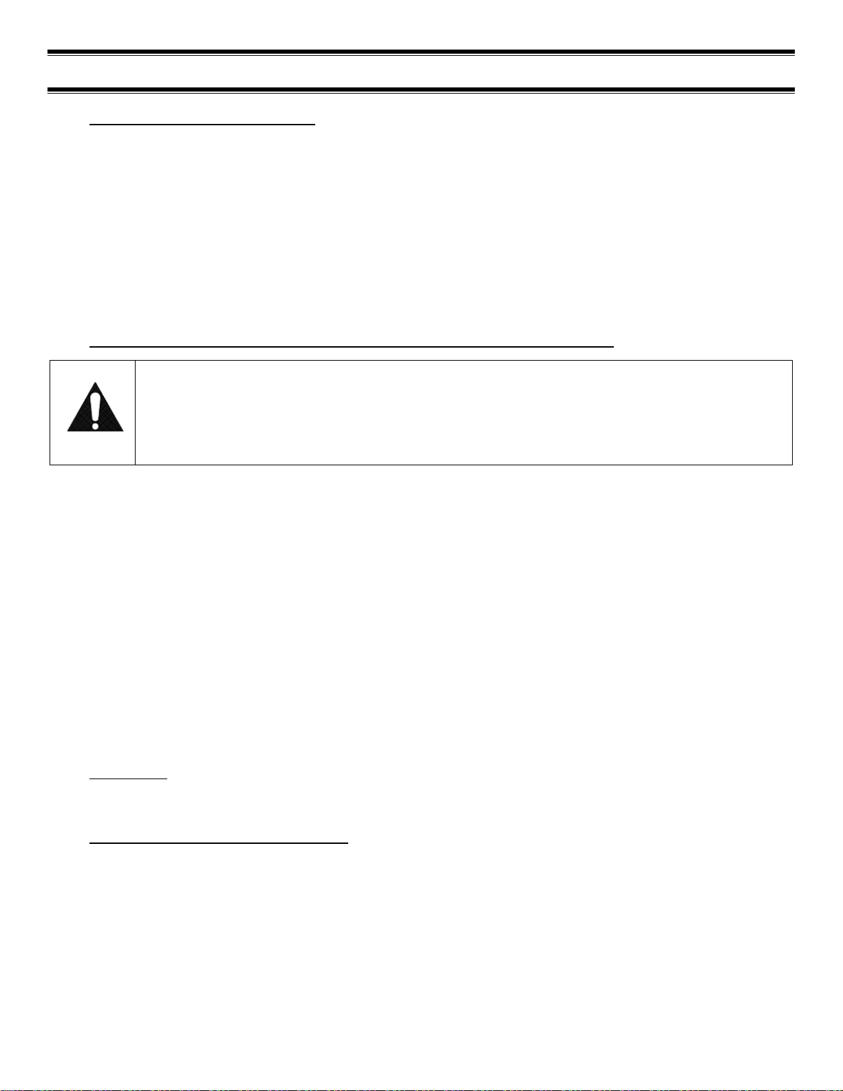
See the electrical data plate located at the rear of the case for proper circuit size and wire ampacity.
The electrical connection box is accessible from the rear of the case with rear grill removed.
FIELD CONNECTION BOX
POWER CORD OR
CONDUIT CONNECTION
HOLE (7/8"O)
REAR BASE
PANEL
(6) REAR BASE
PANEL SCREWS
Page 8 of 40
(5) INSTALLATION INSTRUCTIONS
5.1 LOCATING THE DISPLAY CASE
The case should be located where it is not subjected to the direct rays of the sun, heating ducts, grills,
radiator, or ceiling fans, nor should it be located near open doors or main door entrances. Also, avoid
locations where there are excessive air movement or air disturbances.
The case requires a minimum of 6 inches of clearance at the rear of the unit for air discharge. Do not locate
case with back tight against the wall. The louvers located on front of base must remain clear for air intake. If
rear clearance or front clearance is not possible see a Federal representative for air intake and discharge kit
options.
No clearance is needed on sides of the unit.
5.2 REMOVING CASE FROM SHIPPING SKID AND GENERAL INSTALLATION
CAUTION:
Do not push or pull against the top panel, plastic end, end glass, or door frames when
removing the case from the skid or moving the case. Case damage or glass breakage could
result.
1. Remove crate top and sides and note missing or damaged items as explained in the pre-installation
procedures outlined above.
2. Move the case as near as possible to the final location and before removing it from the shipping skid.
3. Remove the (4) brackets that secure the case to the shipping skid.
4. Prepare cabinet according to instructions in this section that pertain to your model.
5. Lift the case off of skid and into required position. Only lift the case from under the rear lip and front
bottom trim channel above the base. Note: Do not push or pull on front bottom trim channel or lift
using the plastic end panel.
6. The case must be level for proper drainage of defrost condensate to the condensate evaporator. Using
the wrench provided level and square the case as needed by adjusting the leg leveler in each corner of
base. The 6ft cases also have a set of leg levelers in the center. These must be adjusted so the base is
flat.
7. The leveled case must be sealed to the floor using a NSF listed sealant.
5.3 CLEANING
For initial setup, clean the case as outlined in the “Weekly Cleaning” section of this manual.
5.4 CENTER PANEL JOINING (OPTION)
If your cases where ordered with the Center Panel Joining Option you will need to perform the following
installation procedures.
Page 9 of 40
FRONT JOINING
BRACKET
REAR JOINING TRIM
CENTER PANEL
BASE MOUNTING
HOLES (4)
RIGHT CASE
LEFT CASE
LEFT CASE REAR
BASE PANEL
LEFT CASE FRONT
BASE PANEL
TOP JOINING
BRACKET
INTERIOR JOINING FLANGE
1. Place the right case into desired location and level case by adjusting leg levelers with provided
wrench.
2. Remove the front base panel (4) screws and rear base panels (6) screws from the left case. Push
the left case end tightly against the right case end. The rear joining trim on the right case must be
behind the back panel of the left case and the front joining bracket on the right case must be inside
the front aluminum trim channel of the left case.
3. Adjust the leg levelers on the left case so it is level and exactly aligned with the right case. The (4)
base mounting hole in the right case panel must align with the (4) mounting holes located in base
compartment of left case.
4. Push the cases together as tightly as possible and the gap between the cases must be tight and
even. If the gap is larger at the top or the bottom adjust leg levelers accordingly. HOLD CASES
TOGETHER AS TIGHT AS POSSIBLE WHILE ATTACHING ALL JOINING BRACKETS AND DO NOT OVER
TIGHTEN SCREWS OR SCREWS WILL STRIP OUT.
5. Attach the bottom of the left case to the right case center panel base mounting holes through the
holes located inside of the left case base. Use the (4) large 10-12x1/2 screws provided.
6. Attach the rear top of left case through the holes in the rear joining bracket using the (3) black
#10-12x1/2 self drilling screws provided.
7. Attach the front of left case through the holes in the front joining bracket using the (2) smaller
#8-12x1/2 self drilling screws provided.
8. Attach the top of left case through the holes in the top joining bracket using the (2) smaller
#8-12x1/2 self drilling screws provided.
9. Attach the interior of left case through the holes in the interior joining flange using the (3) smaller
#8-12x1/2 self drilling screws provided
10. If any there are any gaps along the joining seam fill them with NSF black silicone.
11. Reinstall front and rear grills.

Page 10 of 40
5.5 REFRIGERATION SYSTEM
5.5.1 Self Contained Models
The self-contained models are shipped from the factory with a completely operational 404A
refrigeration system and require no modifications or adjustments upon installation. Case must be
installed as per the installation section of this manual to provide proper condensing air cooling.
5.5.2 Remote Models
The remote models are designed to use 404A refrigerant and shipped from the factory with the
evaporator coil, expansion valve, sight glass, service valves and refrigerant solenoid valve. Installation
must be performed by a licensed Refrigeration Technician. See the Service section of this manual for
installation requirements.
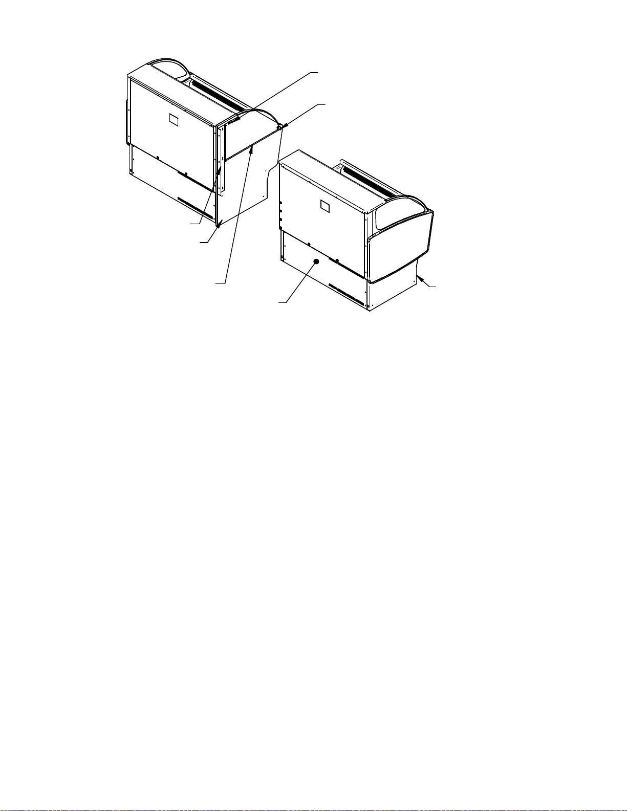
5.6 EVAPORATOR CONDENSATE DRAIN TUBE
WARNING TO INSTALLER:
Evaporator Condensate Drain Tube may become dislodged during shipping. Installer must
check Evaporator Condensate Drain Tube upon installation to be sure drain tube is properly
seated and installed correctly.
Evaporator Drain Tube must be attached to tube protruding from bottom of Evaporator Tub and must either
be inside the Condensate Pan area or inside of hole of Condensate Pump.
Page 11 of 40
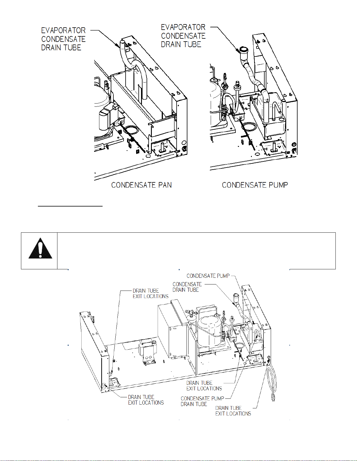
5.7 CONDENSATE PUMP
A condensate pump is Standard on some models and Optional on all models. Installer must check unit to see if
a condensate pump has been provided with case.
WARNING TO INSTALLER:
Installer must determine if case was provided with condensate pump. Failure to hook up
pump hose to drain will cause water on floor and cause a slip hazard.

Page 12 of 40
Instead of using heat energy to remove condensate run off from the evaporator coil a condensate pump
moves the water to a nearby drain.
• The Condensate Pump is provided with 50ft of clear 1/2in OD x 3/8in ID tubing that must be run out of
the base area to a drain.
• There are several drain tube exit locations provided in the base as noted in the drawing above. Plugs or
caps will need to be removed in the desired exit location.
• The hose can be run the entire 50ft in any direction as required, but no higher than 20ft from the
pump base. A check valve is provided in the pump to prevent water from flowing back into the
reservoir. For best efficiency extend the hose level below the level of the pump base to create a
siphoning effect. Never run the hose to or through an area below freezing (32°F, 0°C) or freezing water
will block the tube.
 Loading...