

Page 1
- 1 -
E3335
REV. K 6/9/20
INSTALLATION & OPERATIONS MANUAL
FEDERAL INDUSTRIES
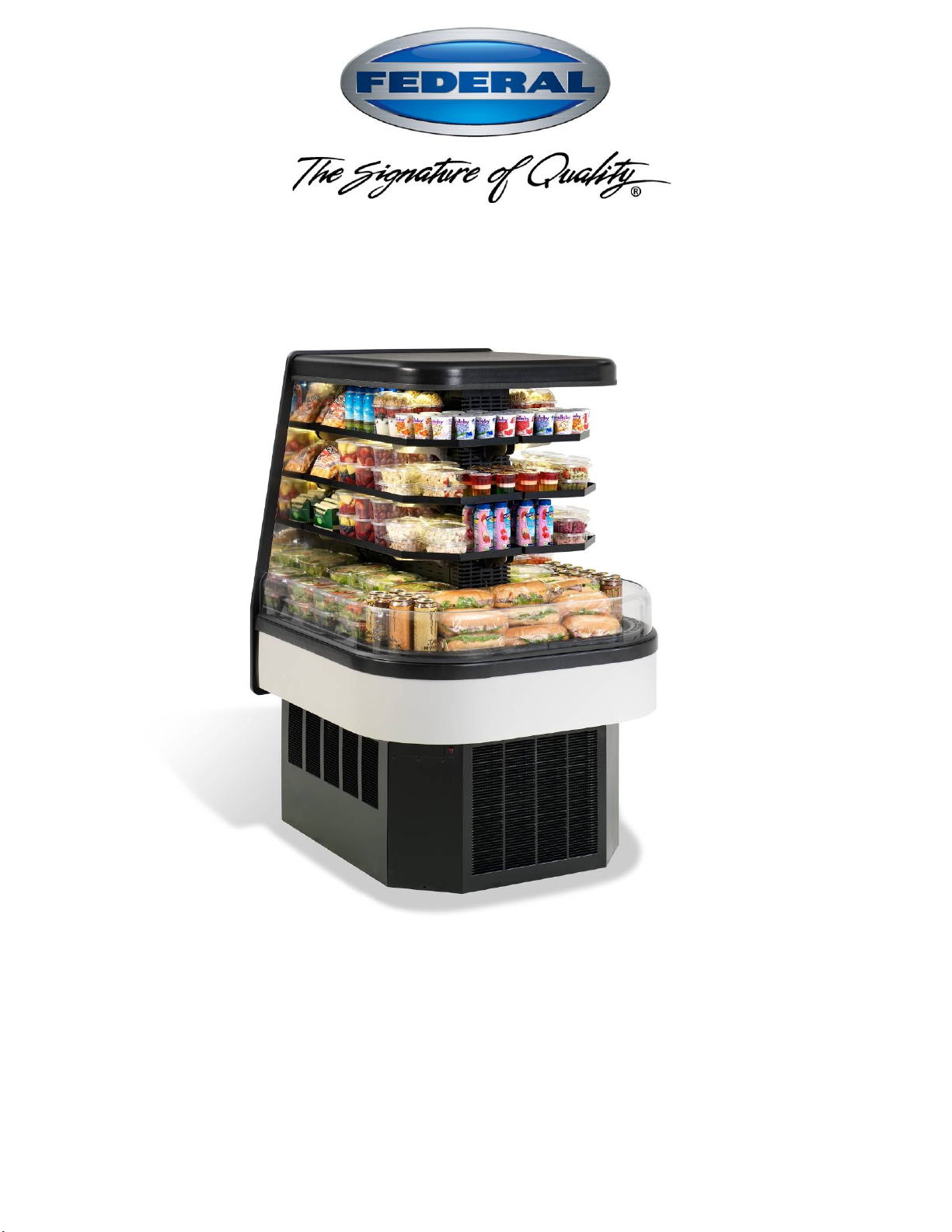
ECSS40 & ECSS60 MODELS
KEEP THIS MANUAL FOR FUTURE REFERENCE
Engineering and technical data are subject to change without notice.
FEDERAL INDUSTRIES 215 Federal AVE Belleville, WI 53508
Toll Free 1(800) 356-4206 WI Phone (608) 424-3331 Fax: (608) 424-3234
ECSS E3335
Page 2

- 2 -
CONTENTS
INTRODUCTION ....................................................................................................................................... 3
WARNING LABELS & SAFETY INSTRUCTIONS ............................................................................. 4
PRE-INSTALLATION PROCEDURES .................................................................................................. 5
INSPECTION FOR SHIPPING DAMAGE ............................................................................... 5
INSTALLATION INSTRUCTIONS......................................................................................................... 5
LOCATING THE DISPLAY CASE .......................................................................................... 5
ELECTRICAL CONNECTION ................................................................................................. 5
PERMANENT CONNECTED .................................................................................................. 6
CORD CONNECTED ............................................................................................................... 6
ELECTRICAL DATA .............................................................................................................. 7
REMOVING CASE FROM SHIPPING SKID .......................................................................... 8
REMOVING PACKAGING MATERIAL ................................................................................. 8
LEVELING THE CASE ............................................................................................................. 8
SEALING THE UNIT TO THE FLOOR ................................................................................... 8
BASE PANELS REMOVAL...................................................................................................... 9
SIDE PANELS ........................................................................................................................... 9
END PANELS ........................................................................................................................... 9
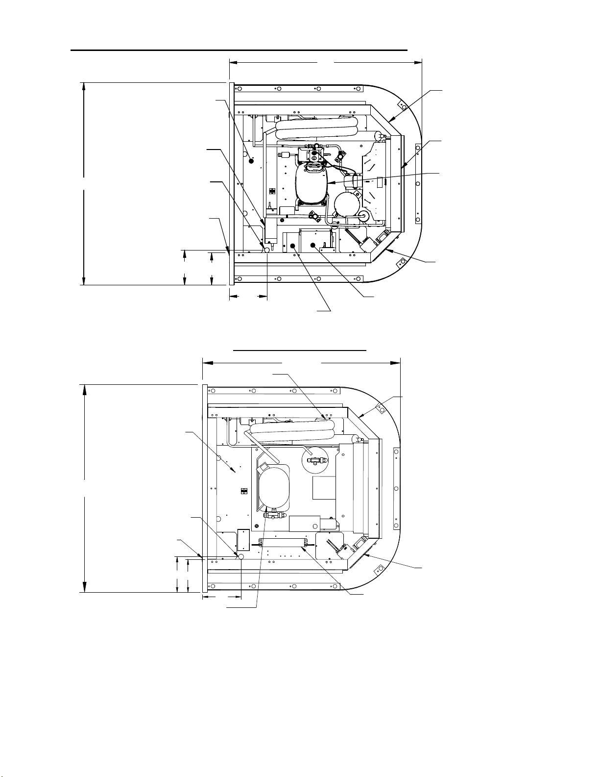
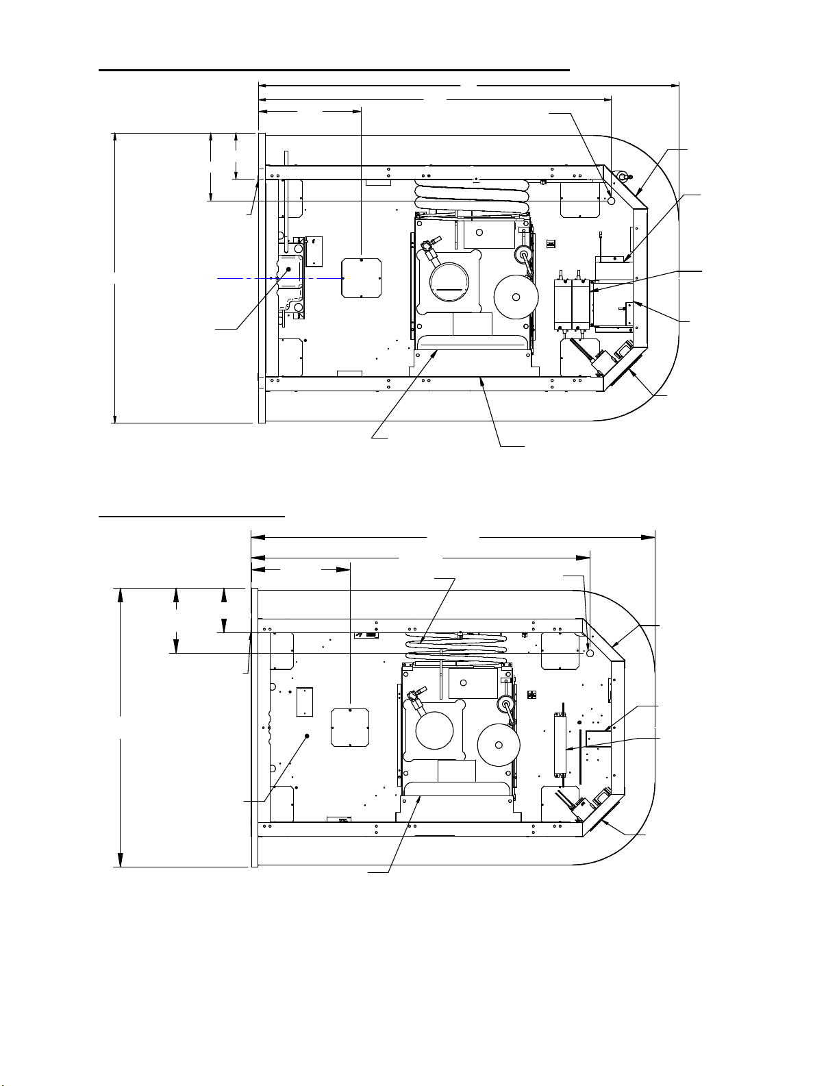
BASE COMPONENT LAYOUT SELF CONTAINED ...................................................... 10-11
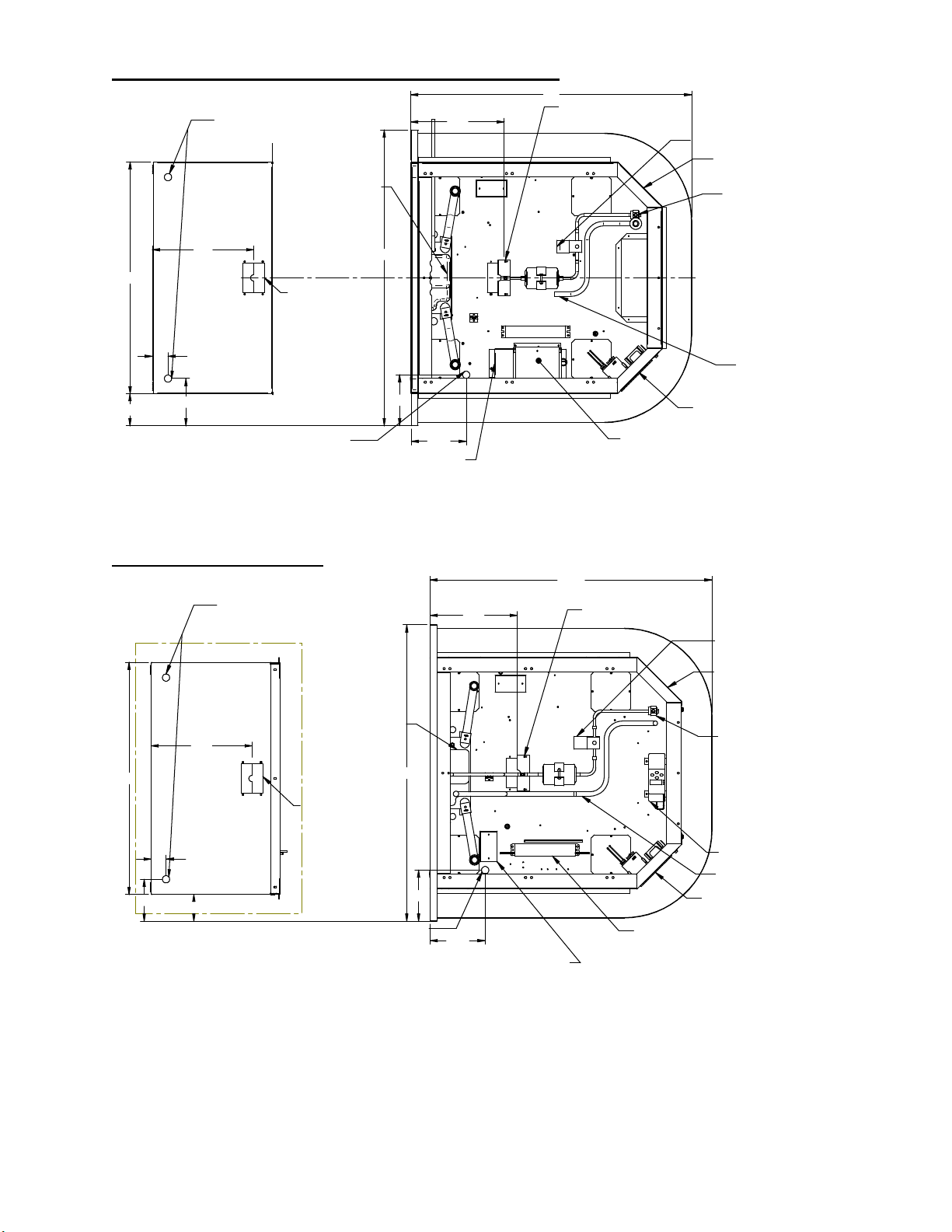
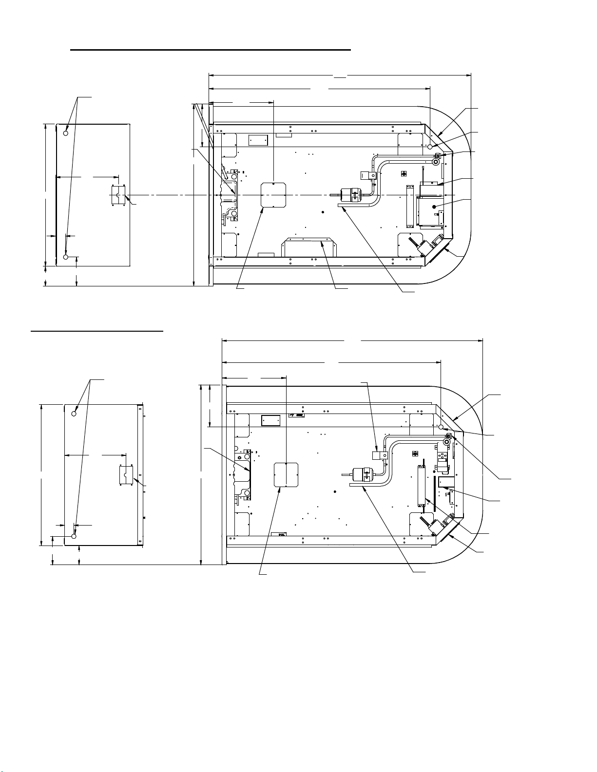
BASE COMPONENT LAYOUT REMOTE ....................................................................... 12-13
CONDENSATE PUMP STANDARD ..................................................................................... 14
CONDENSATE EVAPORATOR PAN ................................................................................... 15
SHELVES ............................................................................................................................ 16-17
OPERATING INSTRUCTIONS ............................................................................................................. 18
USER CONTROLS .................................................................................................................. 18
POWER SWITCH ................................................................................................................... 18
LIGHT SWITCH ..................................................................................................................... 18
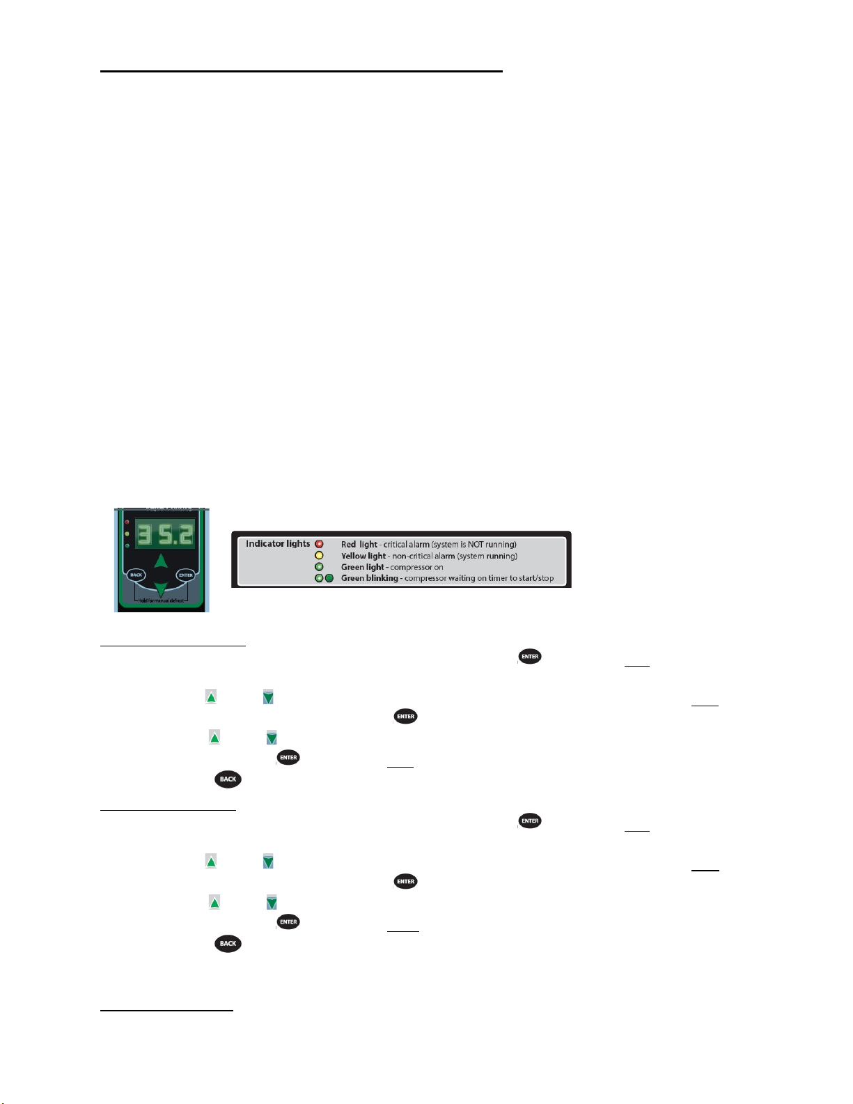
ELECTRONIC CONTROL ................................................................................................ 18-20
CONTROL OPERATION ....................................................................................................................... 21
ELECTRONIC CONTROL ..................................................................................................... 21
OPERATION ........................................................................................................................... 21
DEFROST CYCLE .................................................................................................................. 21
MAXIMUM RUN TIMER ...................................................................................................... 21
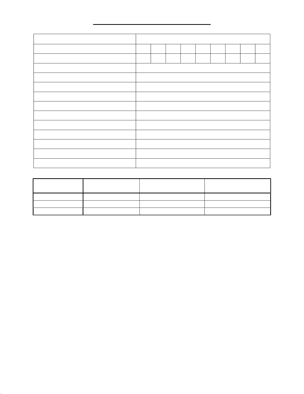
CONTROL PARAMETERS SELF-CONTAINED ................................................................ 21
CONTROL PARAMETERS REMOTE ............................................................................. 22-23
REFRIGERATION OPERATION ......................................................................................................... 24
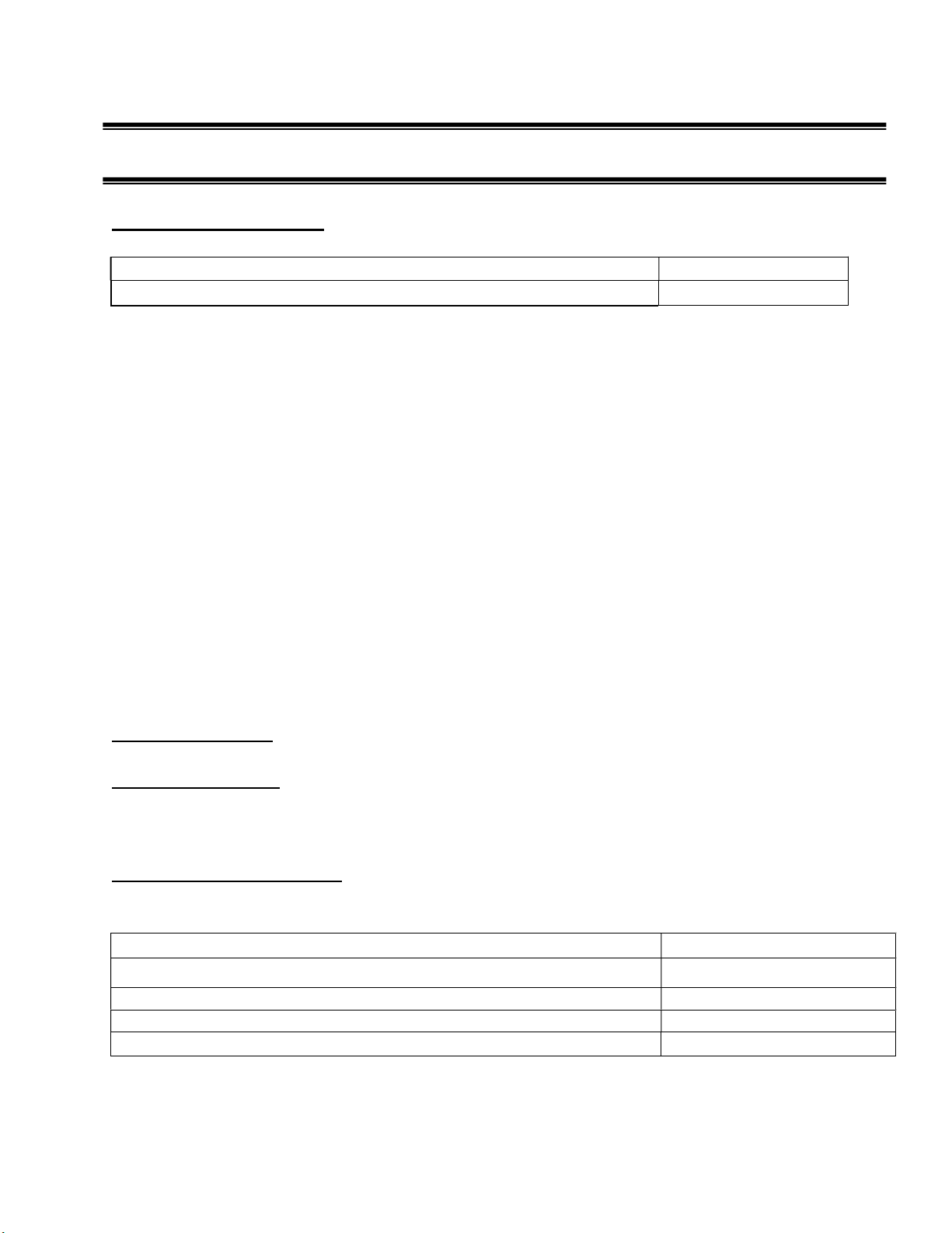
SELF CONTAINED OPERATION ........................................................................................ 24
REMOTE OPERATION .......................................................................................................... 24
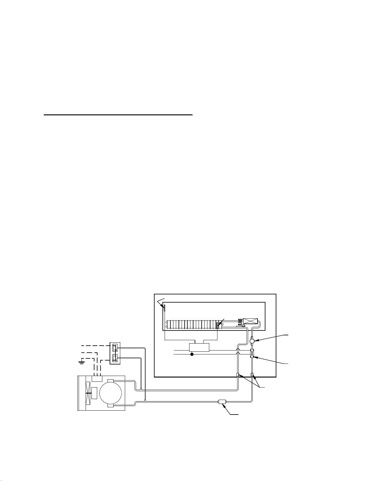
REMOTE CONDENSING UNIT INSTALLATION ............................................................... 25
ELECTRONIC EXPANSION VALVE (EEV)………………………………………………..26
INITIAL START UP ................................................................................................................ 27
PLACING PRODUCT IN CASE ............................................................................................. 27
CLEANING INSTRUCTIONS ........................................................................................................... 27-29
ACRYLIC AIR DEFLECTOR .................................................................................................. 27
DAILY CLEANING & WEEKLY CLEANING ................................................................. 28-29
MAINTENANCE - CLEANING CONDENSER COIL .......................................................................... 30
SERVICE INFORMATION .................................................................................................................... 31
PRE-SERVICE CHECKLIST .................................................................................................. 32
SPECIAL SERVICE SITUATIONS ........................................................................................ 33
SALE & DISPOSAL ................................................................................................................................. 33
REPLACEMENT PARTS - ................................................................................................................ 34-35
WIRING DRAWING ............................................................................................................ 36-57
ECSS E3335
Page 3
- 3 -
INTRODUCTION
Thank you for purchasing a Federal Industries Merchandiser. This manual contains important
instructions for installing and servicing the RSSM, Refrigerated Self-Service Merchandisers. A
repair parts list is also included in the manual. Read all of these documents carefully before
installing or servicing your case.
NOTICE
Read this manual before installing your case. Keep this manual and refer to it before
doing any service on the equipment. Failure to do so could result in personal injury or
damage to the case.
NOTICE
Installation and service of the electrical components in the case must be performed by a
licensed electrician.
The portions of this manual covering components contain technical instructions intended only
for persons qualified to perform electrical work.
DANGER
Improper or faulty hookup of electrical components in the case can result in severe
injury or death.
All electrical wiring hookups must be done in accordance with all applicable local,
regional, or national standards.
NOTE: UNIT MUST BE GROUNDED
REGISTRATION & SERIAL NUMBER
It’s important to keep a record of the model and serial number of your merchandiser for warranty
and part identification. Please write them here for your quick reference.
Register your product online! Visit our website at www.federalindustries.com and register
your product today.
Case Model__________________________ Serial Number______________________
We’re here to provide you with the best possible experience with your new product, however, we
cannot cover everything about your merchandiser in this manual, so if you have any additional
questions or issues, please see the SERVICE INFORMATION PAGE to find who you should
contact.
ECSS E3335
Page 4
- 4 -
WARNING LABELS & SAFETY
INSTRUCTIONS
This is the safety-alert symbol. When you see this symbol on your case or
in the manual, be alert to the potential for personal injury or damage to
your equipment.
Be sure you understand all safety messages and always follow recommended precautions and safe
operating procedures.
NOTICE TO EMPLOYERS
You must make sure that everyone who installs, uses, or services your case is thoroughly familiar
with all safety information and procedures.
Important safety information is presented in this section and throughout the
manual. The following signal words are used in the warning and safety messages:
DANGER: Severe injury or death will occur if you ignore the message.
WARNING: Severe injury or death can occur if you ignore the message.
CAUTION: Minor injury or damage to your case can occur if you ignore the message.
NOTICE: This is important installation, operation, or service information. If you ignore the message,
you may damage your case.
The warning and safety labels shown throughout this manual are placed on your Federal
Industries case at the factory. Follow all warning label instructions. If any warning or
safety labels become lost or damaged, call our customer service department at 1(800)
356-4206 for replacements.
CAUTION
RISK OF ELECTRIC
SHOCK DISCONNECT
POWER BEFORE
SERVICING UNIT.
91-12340
This label is located behind the removable base This label is located below panels
and under the display deck pans. display deck pans.
ECSS E3335
C A UT IO N
H A Z A R D O U S M OV IN G P AR T S
D O N O T O P E R A T E U N IT W IT H
D IS PL A Y P A N S R E M OV E D .
Page 5
- 5 -
PRE-INSTALLATION PROCEDURES
Inspection For Shipping Damage
You are responsible for filing all freight claims with the delivering truck line.
Inspect all cartons and crates for damage as soon as they arrive. If damage is
noted to shipping crates, cartons, or if a shortage is found, note this on the bill of
lading (all copies) prior to signing.
If damage is discovered when the case is uncrated, immediately call the
delivering truck line and follow-up the call with a written report indicating
concealed damage to your shipment. Ask for an immediate inspection of your
concealed damaged item. Crating material must be retained to show the
inspector from the truck line.
INSTALLATION INSTRUCTIONS
Locating The Display Case
The case should be located where it is not subjected to the direct rays of the sun,
heating ducts, grills, radiator, or ceiling fans, nor should it be located near open
doors or main door entrances. Also, avoid locations where there is excessive air
movement or air disturbances and avoid high humidity locations such as near
cases with water misting or fogging devices. Failure to locate this case as stated
will reduce the performance of your Island display and will affect temperature of
interior of case and product.
The case requires a minimum of 48” of clearance on the three service sides of
unit. The paneled side can be placed directly against wall.
Electrical Connection
DANGER: Improper or faulty hookup of electrical components in the
display case can result in severe injury or death.
Permanent Connected (Standard)
-Only a licensed electrician must perform all case electrical connections.
-All electrical wiring hookups must be done in accordance with all applicable local,
regional, or national electrical standards.
-A separate circuit for each display case is required to prevent other appliances on the
same circuit from overloading the circuit and causing malfunction.
-The electrical service must be grounded upon installation.
See the electrical data plate located on the base end, for proper circuit size and wire
ampacity.
ECSS E3335
Page 6
- 6 -
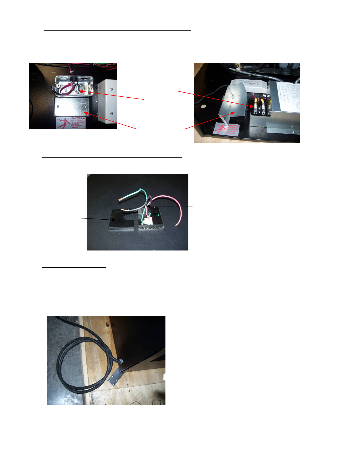
.Standard Base Electrical Connection: There are (2) different styles of
BOX COVER
electrical box connections as shown in pictures below. The electrical connection box is
in the base for floor electrical connection. The box is accessible by removing the base
panel. See “Panel Removal Section” of this manual for panel removal instructions.
Remove electrical box cover to access electrical connection.
PERMANENT
CONNECTION
TERMINAL
BLOCK
OR WIRE
PERMANENT
CONNECTION
ELECTRICAL
Optional Top Electrical Connection: The electrical connection box is
accessible on the top of the case for ceiling drop electrical connection. Remove
electrical box cover to access electrical connection.
PERMANENT
PERMANENT
CONNECTION
ELECTRICAL
BOX COVER
CONNECTION
WIRES
Cord Connected (OPTION)
-A factory installed optional power cord is properly sized to the amperage requirements
of the case. See the electrical data plate located on the rear exterior of the case for the
proper circuit size for each case.
- The cord is factory installed protruding from the corner of the case.
-A separate circuit for each display case is required to prevent other appliances on the
same circuit from overloading the circuit and causing malfunction.
ECSS E3335
Page 7
- 7 -
ELECTRICAL DATA
Model ECSS40SC/ECSS60SC ECSS40R/ECSS60R
Power Suppy, Volts 230 Volts 230 Volts
Frequency 60 Hertz 60 Hertz
Phase 1 Phase 1 Phase
Number of Wires 2 + GND 2 + GND
AMPS VOLTS AMPS VOLTS
Compressor 9.0 / 11.0 230V - -
Condenser Fan 2.6 230V - -
Base Fan - - .15 230V
Evaporator Fan Motor (EACH) 0.15 ea. 230V 0.15 ea. 230V
Lights Power Supply 24V .8 230V .8 ea 230V
Condensate Heater 7.8 230V 7.8 230V
Opt. Condensate Pump .75 240V .75 240V
Refer to the rating plate data attached to side of base for Maximum Fuse Size and
Minimum Circuit Ampacity.
ECSS E3335
Page 8
- 8 -
skid or moving the case.
Removing Case From Shipping Skid
CAUTION: Do not push against the clear acrylic deflector around the sides and nose.
Doing so can cause the acrylic to break.
Do not lift or push on the top canopy located on top of the case.
Doing so can permanently damage the tower frame.
Care must be taken not to damage or tip the case when removing it from the
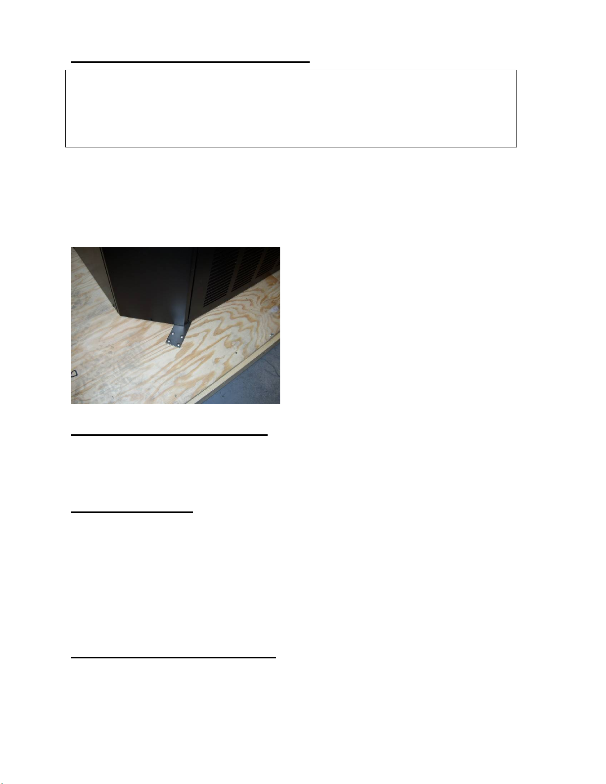
Remove the screws and brackets that secure the case to the skid. Remove the
brackets from the case.
Note that the case may have optional wheels installed and once the brackets
holding the case to the skid are removed the case will roll.
Removing Packaging Material
Remove bubble wrap and packing material for all shelves and panel, brackets,
etc. If it is necessary to remove tape residue from plastic materials, use cleaning
compounds recommended in the cleaning section of this manual.
Leveling The Case
The case must be level for proper drainage of defrost water to the condensate
pump.
Check the level of the case where the display overhangs the base.
Adjust levelers as needed to level the case side to side.
A wrench is included to aid in adjusting leg levelers.
NOTE: Use a wood or plastic shim under each leg leveler to avoid scratching the
tile floor.
SEALING THE UNIT TO FLOOR
After the unit is positioned and the leg levelers are turned out, the unit needs to be
sealed to the floor for NSF approved installation.
ECSS E3335
Page 9
- 9 -
Base Panel Removal
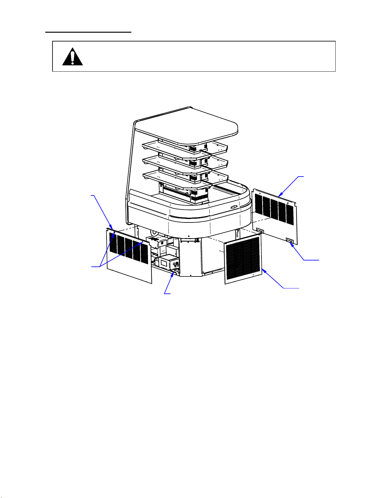
DANGER: Electric shock hazard. Do not operate unit with panels removed.
Panels must be in place when operating the case.
LEFT SIDE PANEL
RIGHT SIDE PANEL
1/4 TURN PANEL
RETAINER SCREWS
(TYPICAL)
Typical Panels Removal
1. Loosen the (2) ¼ turn retainer screws from top of panel.
(The screws will stay on the panel even after they are detached from base)
2. Tilt the top of the panel away from the base and pull up on panel to allow the
side panel hooks to pull out of the side panel slots.
3. Set the panel in safe place to prevent damage.
4. Reinstall panels in the reverse order.
PANEL BOTTOM RETAINING
SLOTS (TYPICAL)
SIDE PANEL HOOK
FRONT NOSE
PANEL
ECSS E3335
Page 10
- 10 -
Base Component Layout ECSS40SC Self Contained
40
CONDENSATE PUMP OR
OPTIONAL CONDENSATE
EVAPORATOR
DATA PLATE
LOCATION
LIGHT POWER SUPPLY
7/8 FLOOR ELECTRICAL
41
CONNECTION LOCATION
7/8 BACK PANEL
ELECTRICAL CONNECTION
LOCATION FOR OPTIONAL
POWER CORD
7.0
6.5
7.6
POWER CONNECTION BOX
LAYOUT AFTER 12/1/19
CONDENSING
COIL
CONDENSING
COIL
CONDENSING
UNIT
CONTROL PANEL
LOCATION
ELECTRICAL BOX
40
DATA PLATE
LOCATION
CONDENSATE EVAPORATOR
OR OPTIONAL CONDENSATE
PUMP
41
7/8 FLOOR ELECTRICAL
CONNECTION LOCATION
7/8 BACK PANEL
ELECTRICAL CONNECTION
LOCATION FOR OPTIONAL
POWER CORD
7.0
6.5
CONDENSING
UNIT
7.6
CONTROL PANEL
LOCATION
LIGHT POWER SUPPLY
ECSS E3335
Page 11
- 11 -
Base Component Layout ECSS60SC Self Contained
60
14.5
49.6
7/8 FLOOR ELECTRICAL
CONNECTION LOCATION
6.5
9.58
7/8 BACK PANEL ELECTRICAL
CONNECTION LOCATION
FOR OPTIONAL POWER CORD
41
CONDENSATE PUMP
OR OPTIONAL
CONDENSATE
EVAPORATOR
C
L
LAYOUT AFTER 12/1/19
14.5
SLIDE OUT
CONDENSING UNIT
49.7
CONDENSING COIL
60
7/8 FLOOR ELECTRICAL
CONNECTION LOCATION
DATA PLATE
LOCATION
POWER
CONNECTION
BOX
LIGHT
POWER
SUPPLYS
ELECTRICAL
BOX
CONTROL
PANEL LOCATION
CONDENSING
COIL
9.58
7/8 BACK PANEL ELECTRICAL
CONNECTION LOCATION
FOR OPTIONAL POWER CORD
41
6.5
CONDENSATE
EVAPORATOR
OR OPTIONAL
CONDENSTAE
PUMP
SLIDE OUT
CONDENSING UNIT
DATA PLATE
LOCATION
POWER
CONNECTION
BOX
LIGHT POWER
SUPPLY
CONTROL PANEL
LOCATION
ECSS E3335
Page 12
- 12 -
Base Component Layout ECSS40R Remote
40
7/8 BACK PANEL ELECTRICAL
CONNECTION LOCATION
FOR OPTIONAL POWER CORD
CONDENSATE PUMP
OR OPTIONAL
CONDENSATE
EVAPORATOR
14.1
32
40.91
REFRIGERATION
REAR ACCESS
COVER
13.0
REFRIGERATION FLOOR
ACCESS COVER
3/8 LIQUID SOLENOID
DATA PLATE
LOCATION
SITE GLASS
C
L
2.2
4.4
6.5
7/8 FLOOR ELECTRICAL
CONNECTION LOCATION
LAYOUT AFTER 12/1/19
7/8 BACK PANEL ELECTRICAL
CONNECTION LOCATION
FOR OPTIONAL POWER CORD
13.9
32
REFRIGERATION
REAR ACCESS
COVER
2.1
6.5
4.4
7/8 FLOOR ELECTRICAL
CONNECTION LOCATION
7.01
POWER CONNECTION
BOX
CONDENSATE
PUMP
40.9
7.05
7.62
12.0
7.59
POWER CONNECTION
BOX
5/8 SUCTION LINE
CONTROL
PANEL LOCATION
ELECTRICAL
BOX
40
REFRIGERATION FLOOR
ACCESS COVER
3/8 LIQUID
SOLENOID
DATA PLATE
LOCATION
SIGHT
GLASS
VALVE CONTROL
5/8 SUCTION LINE
CONTROL
PANEL LOCATION
LIGHT POWER SUPPLY
ECSS E3335
Page 13
- 13 -
Base Component Layout ECSS60R Remote
7/8 BACK PANEL ELECTRICAL
CONNECTION LOCATION
FOR OPTIONAL POWER CORD
CONDENSATE PUMP
OR OPTIONAL
CONDENSATE
14.1
32.00
2.2
4.5
6.5
LAYOUT AFTER 12/1/19
EVAPORATOR
REFRIGERATION
REAR ACCESS
COVER
40.91
9.58
14.50
REFRIGERATION FLOOR
ACCESS COVER
49.66
60.0
OPTIONAL
BASE FAN
60
C
L
CONTROL
PANEL LOCATION
5/8 SUCTION LINE
DATA PLATE
LOCATION
7/8 FLOOR ELECTRICAL
CONNECTION LOCATION
SITE GLASS
POWER CONNECTION
BOX
ELECTRICAL
BOX
49.7
7/8 BACK PANEL ELECTRICAL
CONNECTION LOCATION
FOR OPTIONAL POWER CORD
13.9
32
2.1
6.5
4.5
CONDENSATE
PUMP
REFRIGERATION
REAR ACCESS
COVER
9.6
41
14.5
3/8 LIQUID SOLENOID
REFRIGERATION FLOOR
ACCESS COVER
DATA PLATE
LOCATION
7/8 FLOOR ELECTRICAL
CONNECTION LOCATION
SIGHT
GLASS
POWER CONNECTION
BOX
LIGHT POWER SUPPLIES
CONTROL
PANEL LOCATION
5/8 SUCTION LINE
ECSS E3335
Page 14

- 14 -
Condensate Pump Standard
The pump is mounted in the base compartment and is designed to automatically
remove the condensate water that collects from defrosting the evaporator coil. The
pump has a built-in tank that collects water from the evaporator coil defrost cycle. When
the pump tank is full the pump switches on and pumps water to a remote location for
disposal. When the tank is empty the pump automatically switches off.
The pump is capable of lifting water to a maximum of 20’.
Condensate Discharge Hose.
The case is provided with a 25’ of 3/8ID clear flexible tubing. Depending on options it is
either coiled up on top of the case or in the base compartment.
Hose Coiled in Base
Disconnect Power: Access the hose located in base compartment by removing one
of the base side panels. The hose can be routed to the nearest remote drain through
one of the provided openings or holes Do not run hose in heavy traffic areas and be
sure hose does not get kinked or pinched.
Hose Coiled on Top
Hose coiled on top of the unit is designed to be run vertical to the ceiling before
being routed to the nearest remote drain. The maximum vertical height the hose can
run is 20’ from floor. Once the hose turns to a horizontal direction the hose must
have a downward slope to avoid low spots that water can collect. Be sure the hose
does not get kinked or pinched.
ECSS E3335
Page 15
- 15 -
Condensate Evaporator Pan Shipped Loose (OPTION)
If the optional high output condensate pan was ordered it will be shipped loose in a
separate box. This high output pan must be field mounted and wired by a licensed
electrician.
If there is already a factory condensate pan and mounting brackets installed in the base
compartment they must be removed before installing the optional high output pan.
Unwire the heater wires from the 2x 4 electrical box and cap remaining wire ends with
UL approved wire nuts. NOTE: THESE WIRES CAN NOT BE CONNECTED TO THE FIELD
INSTALLED HIGH OUTPUT PAN.
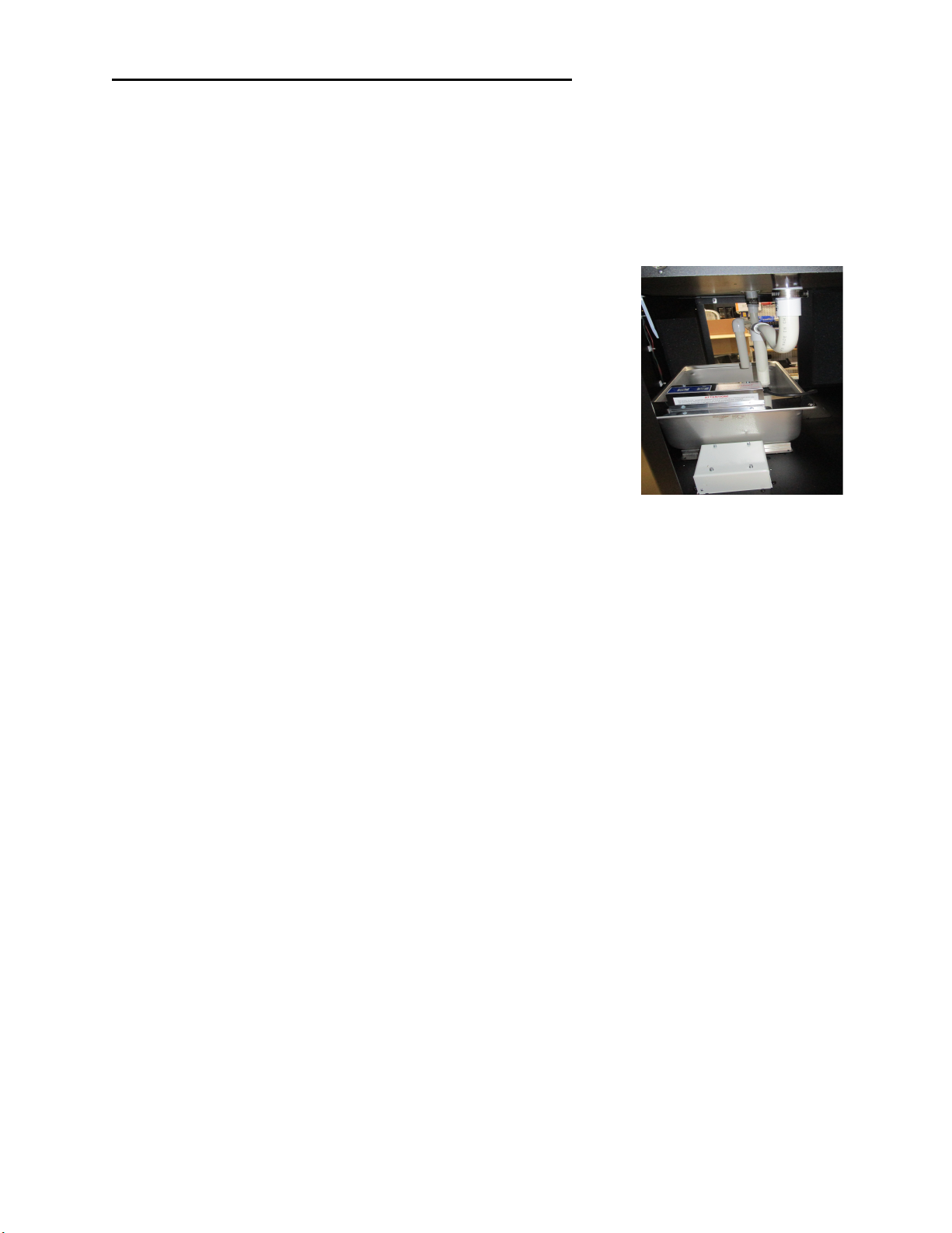
Mount the high output condensate pan inside the base
compartment so that the (2) condensate drain tubes drain
directly into the pan as shown in photo.
The field installed high output condensate pan must be wired
to its own designated circuit breaker and cannot be wired into
the same circuit breaker that the display case uses. The
display case circuit and wiring are not sized to handle the
extra amperage of the high output condensate pan.
See label on condo pan for proper circuit sizing.
- Bottom Electrical (standard): There is cord and plug provided on the high output
condensate pan. a licensed electrician must provide a designated receptacle to plug in
the high output condensate pan. There are access holes in various locations in the base
enclosure to run wires out of the case to electrical source.
-Top Electrical (optional): There is also a top wiring condensate pan option that provides
a top electrical box on the top side of the canopy. This allows wires to be run to the
store ceiling. There are (2) sets of wires, “main case wiring” and “condensate pan
wiring”. Each circuit is labeled and must run to separate circuits. The condensates pan
wires run down through the case into a 2 x 4 electrical box in the base compartment. A
licensed electrician will need to provide a designated receptacle to plug in the high
output condensate pan.
ECSS E3335
Page 16
- 16 -
Shelves
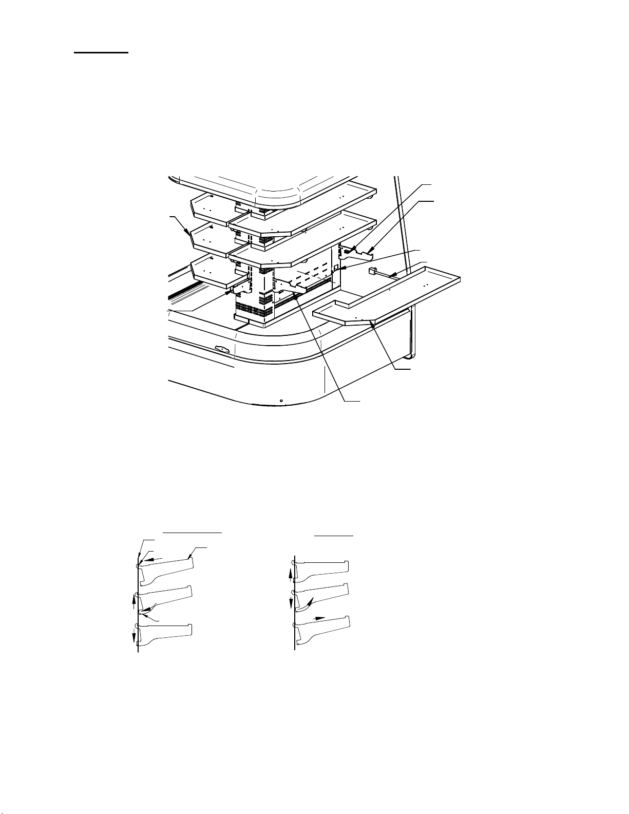
The ECSS has solid metal shelves with LED lighting as standard.
There are (3) brackets required for each shelf (2) long brackets and (1) short
brackets. The long brackets are for the long side of case and the short brackets
are at the short end of case. The long bracket with cord retainer clip must be
used at the panel end back of case where the light cord plugs in.
The shelves are adjustable in ~ 1 1/16” increments.
LEFT SIDE
SHELF ASSEMBLY
SHORT SHELF
BRACKET
CORD CLIP
LONG SHELF
BRACKET WITH
CORD CLIP
FEMALE LIGHT SOCKET
SHELF CORD
RIGHT SIDE
SHELF ASSEMBLY
LONG SHELF BRACKETS
1. Turn the light switch to the off position.
2. Follow the instruction in the illustration below and insert (1) of the (3) shelf brackets in the
desired tower slot on one side of the case. Place the additional shelf brackets in the same
height level on the opposite end of case. The short brackets must go on the short end and (2)
long brackets must go on the long end. The long bracket with a shelf light cord retainer clip
must be on the back side next to the shelf light receptacle.
INSTALLATION
TOWER
TOP HOOK
1
2
3
BOTTOM TAB
4
SHELF BRACKET
3
REMOVAL
1
2
4
1. Place shelf bracket top hook into desired slot in
the tower.
2. Lift shelf bracket top hook to allow shelf bracket
bottom tab to clear slot in tower.
3. Swing shelf bracket bottom tab into tower slot.
4. Place the shelf bracket notch onto bottom of tower
slot.
ECSS E3335
1. Lift shelf bracket up to allow shelf bracket notch
to clear the bottom of slot in tower.
2. Swing shelf bracket bottom tab out of slot in tower.
3. Drop shelf bracket down to allow shelf bracket top
hook to clear the slot in tower.
4. Remove shelf bracket top from slot in tower.
Page 17
- 17 -
3. Set the shelf on to the brackets and place the bracket retainer tip into slots on shelf.
4. Push shelf light cords into plastic shelf cord retainer clip located on inside of shelf bracket.
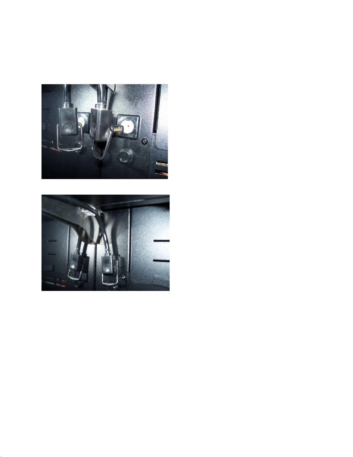
5. Remove the cap from the appropriate female light sockets.
6. If the socket is not being used for a shelf light, the cap must be plugged into socket to prevent
contamination and moisture out of the socket.
7. Plug in each shelf light by aligning the male pins on the appropriate shelf light cord plugs
with the female light sockets and push together. IMPORTANT: Do not roll plug during
insertion.
8. Place extra cord into cord clip as shown to keep it out of the way.
9. Removal of shelving is performed by following steps in reverse order.
ECSS E3335
Page 18
- 18 -
OPERATING INSTRUCTIONS
adjust mode
.
adjust mode
.
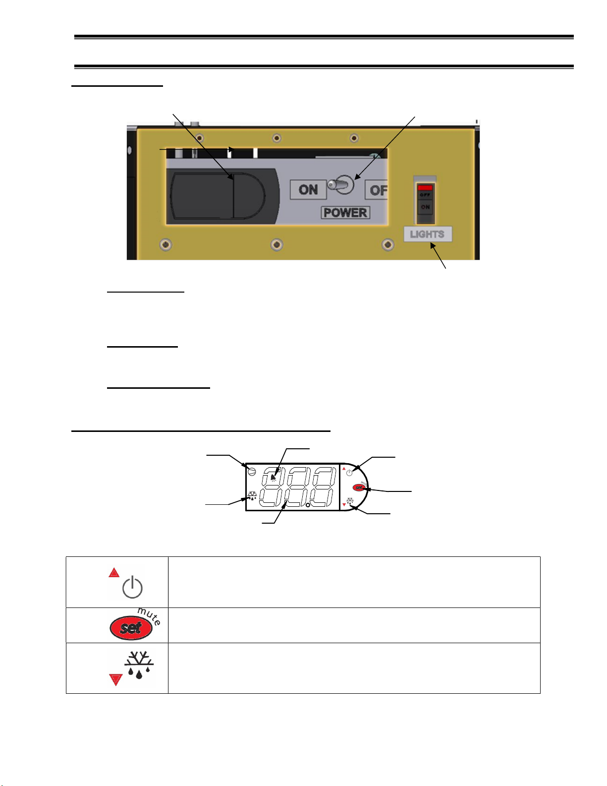
POWER SWITCH
CONTROL
/ DISPLAY
LIGHT SWITCH
User Controls
ELECTRONIC
Power Switch
The unit has a power switch that turns off power to the entire unit, including the
condensate evaporator and the lights. This switch is located behind a lift-up
panel on the unit base.
Light Switch
The unit has a light switch that turns on and off the interior lights of unit. This
switch is located below the lift up panel on the unit base.
Electronic Control
This control is located behind a lift-up panel on the unit base.
Using Electronic Temperature Control (Refrigerated Models Only)
COMPRESSOR RUN
INDICATOR
ALARM INDICATOR
POWER TO CONTROL ON/OFF
AND SET POINT UP ADJUST
SET POINT ADJUST MODE
DEFROST MODE INDICATOR
MANUAL DEFROST AND
DIGITAL DISPLAY
SET POINT DOWN ADJUST
Button Overview
Press and hold this button for 3 seconds to turn
system on (if off) or off (if on).
Also used to adjust set point when in set point
Press to enter set point adjust mode, confirm set
point changes, and mute alarms.
Press and hold this button for 3 seconds to initiate
a manual defrost (and cancel defrost if initiated),
also adjusts set point down when in set point
ECSS E3335
Page 19
- 19 -
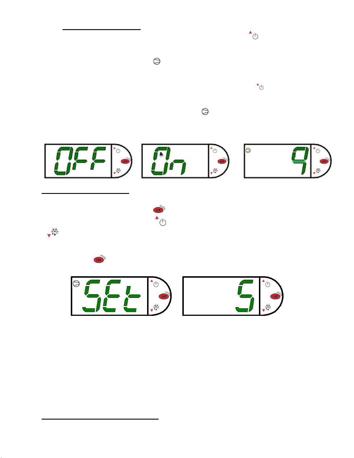
Powering on control
To turn refrigeration control power on, press and hold for approx. five
seconds. The display will read “On” while the button is depressed. When the
control powers on, the display will read the current set point numbers 1 thru 9.
The compressor run indicator will illuminate on the display, meaning that the
compressor is running. (Note: the control may already be in the on mode when
shipped from factory).
To turn refrigeration control power to off, press and hold for approx. five
seconds. The display will read “Off” while the button is depressed. When the
control powers off the display will flash back and forth between the current set
point and “Off”. The compressor run indicator will be off on the display. When
refrigeration control is in the off-mode cabinet lights and evaporator fans will still
operate, but the compressor will not turn on causing the case to gradually reach
room temperature.
Adjusting the set point
The set point is what determines how cold the display case will hold food and beverage. To
adjust the set point press and hold the button approx. 5 seconds until the display begins to
flash a number. Then press the use the button to scroll number up (colder) or press the
button to scroll number lower (warmer). There are nine (9) available set point numbers,
the higher the number of the set point, the colder the display case will run, with setting “9”
being the coldest and setting “1” being the warmest. Once you have chosen your desired
setting press the button again to confirm your choice.
Entering manual defrost mode
ECSS E3335
Page 20
- 20 -
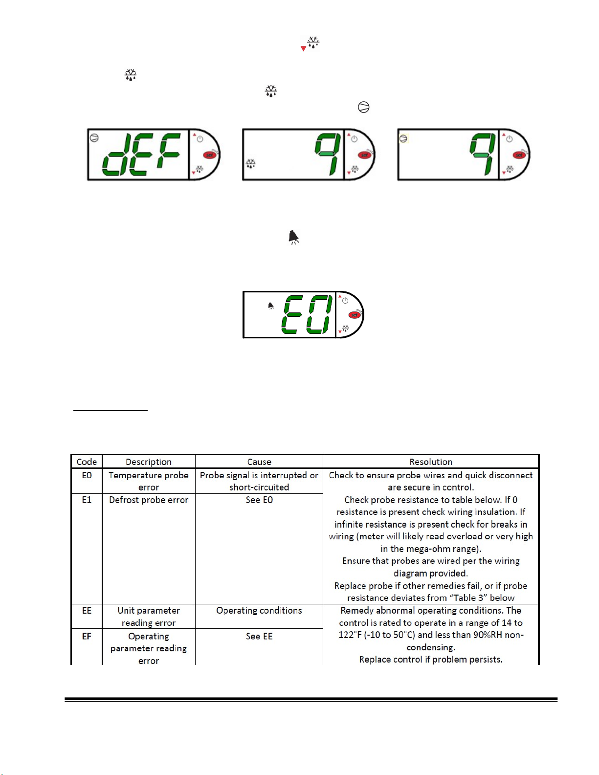
To initiate a manual defrost press and hold the button approx. 5 seconds. The control will
read “dEF” while the button is being held. The defrost is initiated when the defrost mode
indicator illuminates on the display. The control display will then return to reading the set
point. when the defrost mode indicator turns off the defrost is complete and the compressor
will turn back on illuminating the compressor run indicator .
Error codes
It is possible for error codes to be displayed on the control screen. In the event of a malfunction
an alarm will sound and the alarm indicator will be displayed on the display. An error code
or codes will flash intermittently on the display. If there are multiple codes, the display will
continuously cycle through them. The following photo shows error code “E0” as an example.
Mute: You may mute the alarm by pressing and releasing the wrench button. The red ringing bell
and all error codes will still be displayed. When the fault is remedied the control will return to
normal operation and will automatically clear the codes from the display.
Carel Control
EO = Air sensing probe - Open or shorted
E1 = Evap. coil probe - Open or shorted
ECSS E3335
Page 21
- 21 -
CONTROL OPERATION
Electronic Control
This unit is equipped with an electronic temperature control. The control parameters are
set at the factory and cannot be manually changed in the field. Control parameter
changes can only be made by downloading a new set of parameters via a program chip
supplied by Federal Industries.
Operation
The control uses two sensors, one located in the air stream and one located on the
evaporator coil. The sensor located in the air stream is referred to as the temperature
control sensor. The sensor located on the evaporator coil is referred to as the coil
sensor.
The temperature control sensor is located inside the center tower at the top. The sensor
location is critical for proper operation on the unit. Do not move or relocate this sensor.
The coil sensor is strapped to the evaporator coil. This sensor location is critical for
proper operation of the unit. Do not move or relocate this sensor.
The temperature control is set to cut in at 39 degrees F. The Temp control cuts out at
14 degrees F at the coldest setting “9” and 28 degrees F at the warmest setting, ‘1’ on
the control display.
The temp control turns off the refrigeration system when you “press and hold” the top
arrow / power button for approx. 3 seconds until “OFF” flashes on display.
Defrost Cycle
The CAREL control is programmed to initiate defrost via two different methods. There
are 3 programmed defrost cycles in the case which will initiate a defrost cycle every 8
hours. The unit does not have a time clock so the defrost cycles cannot be set for any
specific time of day.
The unit also has an ‘On demand’ defrost feature that will initiate a defrost when the
temperature differential between the evaporator temperature and the air temperature is
more than 15 degrees for 5 minutes after 30 minutes into the refrigeration cycle.
Maximum Run Timer
The unit is equipped with a maximum run timer that is preset at the factory for 75
minutes on. If the temperature control does not reach cut out set point after running for
one hour, the timer will turn the compressor off for a minimum of 2 minutes.
ECSS E3335
Page 22
- 22 -
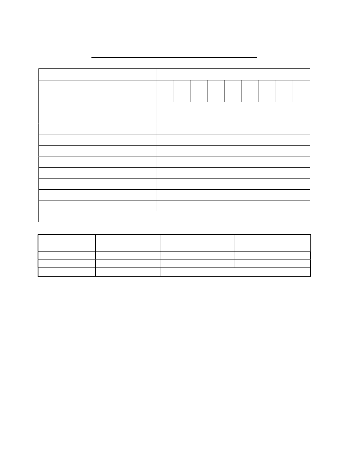
CONTROL PARAMETERS ECSS SELF-CONTAINED
Resistance [
Ω
]
32°F
(0°C)
27.83
27.28
26.74 77°F
(25°C)
10.1
10
9.9
212°F
(100°C)
1
0.97
0.94
Parameter Description
Control Setpoint 1 2 3 4 5 6 7 8 9
Compressor Cut out [°F] 28.0 26.2 24.5 22.7 21.0 19.2 17.5 15.7 14.0
Table 1 - Control Parameters
Compressor Cut in [°F]
Compressor Min On Time
Compressor Min Off Time
Compressor Max Run Time
Defrost Termination Temp [°F]
Time to first defrost
Time to subsequent defrost
Maximum Defrost duration
Defrost on demand differential [°F]
Delay for defrost on demand
Time delay to the next defrost on demand
\Table 2 - Temperature Probe Common Resistance Chart
Probe Temp
Maximum
39.0°
5 min
2 min
75 min
43.0
8 hr.
8 hr.
30 min
15.0
5 min
30 min
Normal Resistance [Ω] Minimum Resistance [Ω]
ECSS E3335
Page 23
- 23 -
CONTROL PARAMETERS ECSS REMOTE
Resistance [
Ω
]
32°F
(0°C)
27.83
27.28
26.74
77°F
(25°C)
10.1
10
9.9
212°F
(100°C)
1
0.97
0.94
Parameter Description
Control Setpoint 1 2 3 4 5 6 7 8 9
Compressor Cut out [°F] 30.0 28.0 26.0 24.0 22.0 20.0 18.0 16.0 14.0
Table 3 - Control Parameters
Compressor Cut in [°F]
Compressor Min On Time
Compressor Min Off Time
Compressor Max Run Time
Defrost Termination Temp [°F]
Time to first defrost
Time to subsequent defrost
Maximum Defrost duration
Defrost on demand differential [°F]
Delay for defrost on demand
Time delay to the next defrost on demand
\Table 4 - Temperature Probe Common Resistance Chart
Probe Temp
Maximum
38.0°
5 min
2 min
60 min
43.0
6 hr.
6 hr.
30 min
18.0
5 min
30 min
Normal Resistance [Ω] Minimum Resistance [Ω]
ECSS E3335
Page 24
- 24 -
Refrigeration R
449A
Charge
ECSS40
6 Pounds
Refrigera
t
ion R
449A
Charge
ECSS60
Refrigeration R
449A
Charge
CHARGED IN FIELD
Remote Low Press. Switch
Cut In
50
psi Remote Low Press. Switch Cut Out
15 psi
Adjustable Head Master
200 psi
Remote High Press. Switch Cut Out
400 psi
REFRIGERATION OPERATION
Self-Contained Models
7.5 Pounds
The self-contained models are shipped from the factory with a completely operational R449A
refrigeration system and require no modifications or adjustments upon installation. Case must be
installed as per the installation section of this manual to provide proper condensing air cooling.
Dual Pressure Control (Self-Contained Models Only)
The dual pressure control is used as a safety device and is factory set. The pressure control works
on a differential. The low-pressure side is a safety to protect the compressor in the case of
refrigerant loss. The high-pressure side is a safety to protect from system failure causing too high
of system pressure. As of 8/1/14 ECSS60 only has integrated dual pressure control on
condensing unit.
The high side of the pressure control is factory set to 400psi and is not adjustable. Low
side setting for the R449a cases are set at 40psi differential for the cutout and 60psi for
the cut-in.
Self-Contained Refrigeration Operation
The unit temperature is controlled by the Electronic control and timers outlined in the control
section of this manual.
Note: The condenser fan runs continuously.
Remote Models
BTU Requirements
ECSS40R – 10,000 BTU’S @20F EVAP / 90F Ambient
ECSS60R – 14,000 BTU’S @20F EVAP / 90F Ambient
Pressure Control Settings
- Use pressure gauges to set pressure control.
The remote models are designed to use R449A refrigerant and shipped from the factory with the
evaporator coil, expansion valve, sight glass and refrigerant solenoid valve. Drier filter most be
ECSS E3335
Page 25
- 25 -
installed in field for proper operation. Electronic control runs identical to the Self-Contained
models except the electronic control opens and closes a refrigeration solenoid valve located on
the suction line instead of turning on and off a compressor. The solenoid valve closes and shuts
off the refrigeration flow to the unit and initiates a pump down cycle. This will allow the remote
low-pressure switch to open and shut off remote compressor.
The condensing unit and pressure controls are optionally supplied from the factory for remote
location installation. The condensing unit must be mounted and wired by the installer. The high
low-pressure switch must be wired in series with the compressor power supply as shown in
diagram below.
Remote Condensing Unit Installation
1. Mount condensing unit as close as possible to the remote display case as practical. Follow
condensing unit manufacturer guidelines for proper piping and distance requirements.
2. All refrigeration and/or electrical materials between the condensing unit and display case are
to be supplied by installing contractor.
3. Route properly sized and designed refrigeration lines from the condensing unit to the cabinet.
Horizontal suction lines should be pitched downward towards the condensing unit at least ½”
per 10’ run to aid the oil drainage. A “P” trap must be installed in the suction line at the foot
of every riser to insure oil return. Dry nitrogen must be used to flow through tubing while
brazing refrigeration lines.
4. Suction line must be insulated the entire length with Armaflex (or equivalent). Do not run
liquid line inside insulation with suction line.
5. The remote high/low-pressure control must be mounted, wired and set pressures by the
installer.
6. Leak check condensing unit, cabinet, and all connecting tubing. Cabinet and condensing unit
tubing should be checked to insure no leaks occurred during shipping or from rough
handling.
Make certain all refrigeration valves are opened and evacuate system to 500 microns. Charge
the system with refrigerant type specified on the data plates.
DISPLAY CASE
AIR TEMP. CONTROL PROBE
FUSED
POWER
SUPPLY
HOT
REMOTE
HIGH LOW
PRESSURE
CONTROL
HIGH
LOW
FUSED
CASE
POWER
EVAPORATOR
COILS
ELECTRONIC
CONTROL
DEFROST
TERMINATE
PROBE
EXPANSION
VALVE
SIGHT GLASS
LIQUID LINE
SOLENOID VALVE
REMOTE
CONDENSING
UNIT
SUCTION LINE (INSULATED)
LIQUID LINE
FIELD CONNECTION
DRIER/FILTER
ECSS E3335
Page 26
- 26 -
Electronic Expansion Valve (EEV) After 12/1/19
A traditional TXV uses springs and a temperature bulb to open and close a valve port that
controls the flow of refrigerant entering the evaporator coil. An electronic expansion valve
(EEV) controls the refrigerant flow much more precisely, increasing the performance and
efficiency of the refrigeration system. The EEV controls the flow of Refrigerant by opening and
closing the valve port based on the response to signals sent to the EEV by an electronic
controller. The electronic Control bases these signals by processing information provided from a
temperature sensor and pressure transducer located on the discharge side of the evaporator coil.
These sensors monitor the evaporator superheat and protects the compressor from any liquid
flood back under low superheat conditions.
EEV Controller Settings
The electronic expansion valve controller also allows the use of different types of refrigerants
without the need to change the expansion valve.
The controller is set from the factory to run on 449A refrigerant and will not need any changes to
the control unless another refrigerant is used.
Note: Check your State and Local regulations for approved refrigerants for your install
location. Federal Industries is not liable for any alternate refrigerants used.
The control is located on the left side of the case.
Note: Never change any of the other setting other than the refrigerant type. It may also be
necessary to change the superheat setting only when using a different refrigerant.
Changing Refrigerant
Access the set point mode by pressing and holding the button until Ctl displays on the
screen.
Use the up or down arrows to advance through the available set points until rFG
displays on the screen and press the botton.
Use the up or down arrows until the desired refrigeration displays on the screen and
press and hold the button until rFG once again displays on the screen.
Press the to return to escape the settings menue.
Changing Superheat
Access the set point mode by pressing and holding the button until Ctl displays on the
screen.
Use the up or down arrows to advance through the available set points until SSP
displays on the screen and press the botton.
Use the up or down arrows to set the desired superheat displays on the screen and
press and hold the button until SSP once again displays on the screen.
Press the to return to escape the settings menue.
Initial Start-Up
ECSS E3335
Page 27
- 27 -
After all the checks outlined in the installation section of this manual have been made, the
case is ready to be put into service. Turn on the Power at the breaker box and flip the
Power Switch and Light Switch on unit to the on position. At start up from a warm unit, it is
recommended that the temperature control is set at a warm setting, such as After the unit
has gone through several cycles, change the control to a mid-range setting, then to a
colder setting if necessary to maintain desired product temperature
NOTICE: This refrigerated display case is designed to operate
in a maximum environment of 75 DEG. F and 55% relative
humidity. Exceeding these limits will cause poor case
performance, excessive sweating & overflow condensate pan.
Placing Product into Case
- Do not exceed 75 pounds of weight per shelf. Heavy product should be distributed
evenly across the entire shelving area.
- Determine desired shelving location before placing product in case. Product must be
removed to readjust shelf location.
- Allow a minimum of 2” between top of product and bottom of shelf.
- Do not overhang the front or rear of shelves with product. Improper clearance in
front and rear of shelf will block the refrigerated airflow and will cause product loss.
-Do not block the slots along the front and rear air discharge slots. Covering
these slots will block the refrigerated airflow and could cause product loss.
-The display deck is removable for cleaning and can become dislodged in shipment. To
ensure proper airflow and performance of the case, make sure that the display deck is
pushed completely down.
-Allow refrigerated models to run for at least two hours before placing pre-chilled
product into unit.
NOTICE: CASE MUST BE STOCKED WITH PRE-CHILLED PRODUCT
ONLY.
CLEANING INSTRUCTIONS
Acrylic Air Deflector Cleaning
NOTICE: Clear acrylic air deflector requires special washing procedures
to prevent hazing and yellowing of material.
NEVER USE paper towels (wet or dry) for cleaning or drying and never use a dry towel.
NEVER USE glass cleaner of any kind.
Lightly dust (not wipe) surface with a damp Micro Fiber towel or chamois. The surface can
then be washed using a small amount of dishwashing detergent such as Dawn or Joy and
lukewarm water. Use a Micro Fiber towel or chamois, applying only light pressure. The cloth
or chamois must be kept free of grit by frequently rinsing. Rinse surface with clear water
and dry by blotting with a damp Micro Fiber towel or chamois.
ECSS E3335
Page 28
- 28 -
Daily Cleaning
The case should be cleaned thoroughly, as described in the weekly cleaning
section, before it is used for the first time.
NOTICE: Avoid splashing or soaking any electrical components
with water to prevent electrical damage to the case.
NOTICE: Shut off lights and power switches and remove all
products from case. Allow sufficient time for the unit to
reach room temperature before proceeding with
cleaning.
NOTICE: Remove all products from the case before proceeding
with cleaning procedure.
NOTICE: Acrylic air deflector requires special washing
procedures to prevent hazing and yellowing of material.
Clean as described in “Acrylic Air Deflector Cleaning”
section of this manual.
Note: For major spills or foreign material buildup use complete weekly
cleaning instructions.
Note: Detergents are not recommended and do not use abrasive cleaners or
pads to prevent scratching of surfaces.
1. Dip rag in warm soapy water and ring out thoroughly. Wipe complete interior
of case and dry with soft dry towel.
2. The remaining exterior surface should be wiped down using any ammoniated
cleaners or soapy warm water and dried with soft dry towel.
3. IMPORTANT: Cleaning the clear acrylic plastic front air deflector. Clean
as described in “Acrylic Air Deflector Cleaning” section of this manual.
Weekly Cleaning
NOTICE: Avoid splashing or soaking any electrical components with
water to prevent electrical damage to the case.
NOTICE: Shut off lights and power switches and remove all products
from case. Allow sufficient time for the unit to reach room
temperature before proceeding with cleaning.
NOTICE: Remove all products from case before proceeding with
cleaning procedure.
NOTICE: Acrylic front air deflector requires special washing procedures
to prevent hazing and yellowing of material.
Note: Detergents are not recommended and do not use abrasive cleaners or
pads to prevent scratching of surfaces.
ECSS E3335
Page 29
- 29 -
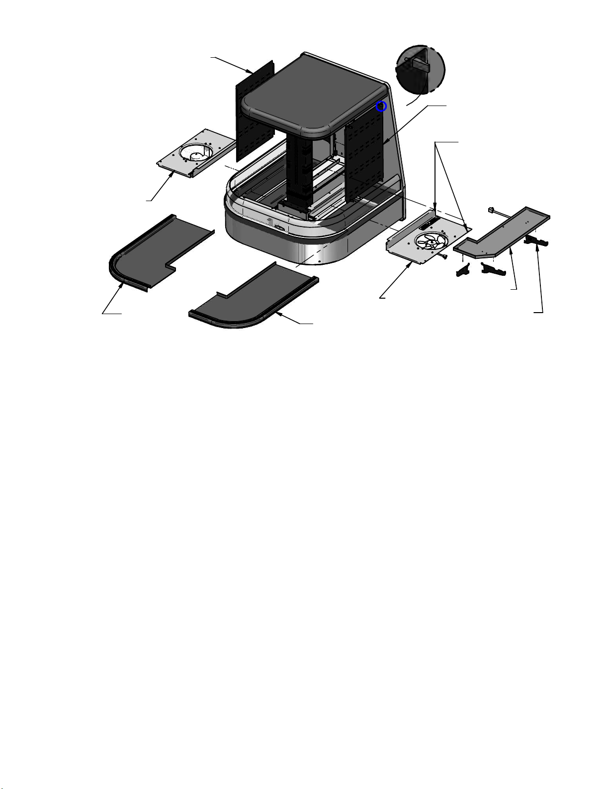
TOWER SIDE PANEL
FAN SHROUD
A
TOWER SIDE PANEL
LATCH (4)
TOWER SIDE PANEL
FAN SHROUD
RETAINER SCREWS (4)
FAN SHROUD
SHELVES (6)
DISPLAY DECK
SHELF BRACKETS
DISPLAY DECK
Remove interior shelving from unit as described in the “Shelving Installation and
Removal” section of this manual.
1. Dip rag in warm soapy water and ring out thoroughly. Clean all shelves and
shelf brackets and dry with soft dry towel.
2. Remove tower side panels by lifting (4) latch levers and pulling tower side panel
out away from tower.
3. Dip rag in warm soapy water and ring out thoroughly. Clean the tower side
panels and inside both tower ends. Dry with soft dry towel
4. Lift the display decks up and out of evaporator tub.
5. Remove the fan shroud assembly by removing (2) retaining screws from the
outer flange and the (2) from the inner flange. Lift the fan shroud assembly and
reach in and unplug the evaporator fan motor cord. Lift fan shroud assembly out
of tub.
6. Clean the display deck(s) using warm soapy water and a brush. Rinse
thoroughly and allow dry. Wipe off fan shroud assembly (do not rinse or
submerge fan motors).
7. Clean the entire interior of the case using warm soapy water. Wipe off all soapy
water with a damp cloth and allow to dry. (DO NOT use solvents such as
Acetone, Benzene, Carbon Tetrachloride, and Lacquer Thinners)
8. IMPORTANT: Cleaning the clear acrylic plastic front air deflector. Clean as
described in “Acrylic Air Deflector Cleaning” section of this manual.
9. Reassemble all components in reverse order.
NOTE: Depending on the amount of usage and spillage of foreign material, some
fasteners may have to be removed and parts disassembled to allow proper cleaning
of the unit.
ECSS E3335
Page 30
- 30 -
MAINTENANCE
Cleaning Condenser Coil
NOTICE: Condenser coil or optional air filter must be cleaned a
minimum of twice per month to insure proper refrigeration
performance and prevent compressor failure. In some
environments, it may be necessary to clean more frequently.
FAILURE TO CLEAN CONDENSER COIL WILL VOID
COMPRESSOR WARRANTY.
It is very important that the Condenser coil or optional air filter is cleaned twice
per month to insure proper refrigeration performance and to prevent compressor
failure. In some environments, it may be necessary to clean more frequently.
Failure to clean condenser coil will void condenser warranty. This procedure is
for Self-Contained models. The remote condenser coil must also be cleaned at
same intervals.
1. Disconnect power to the unit.
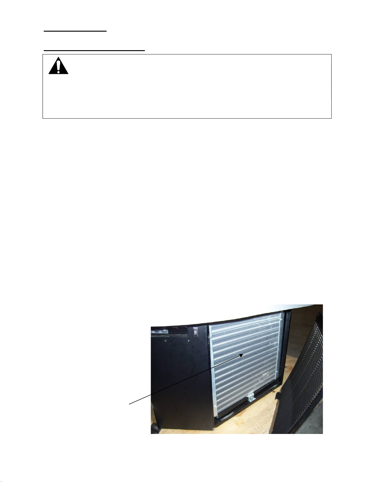
2. On ECSS40 Remove the nose panel and on ECSS60 remove the side panel on
left side of case next to the controls.
Carefully vacuum the front surface of condenser coil. Take care not to bend coil
fins with vacuum cleaner nozzle.
-If equipped with optional air filter remove filter and carefully vacuum the front
surface of condenser coil. Take care not to bend coil fins with vacuum cleaner
nozzle. Wash filter using warm soapy water, rinse, and let dry. Apply a generous
coat of filter coat adhesive to both sides of filter. (Filter coat adhesive is available
through any restaurant supply distributor.) Recommended Super Filter Coat
NOTE: Failure to coat filter with a fresh coat of filter adhesive after
cleaning will prevent filter from working properly. Failure to do so
will allow the condenser coil to plug, which will affect refrigeration
performance and could cause compressor failure.
3. Reinstall side panel(s).
VACUUM FRONT
SURFACE OF
CONDENSER COIL
ECSS40 SHOWN
ECSS E3335
Page 31
- 31 -
SERVICE INFORMATION
DISCONNECT POWER BEFORE
To find a service company in your area, please visit our website at
www.federalindustries.com. There you can also find self-service tools to
For Warranty Service Requests & ALL Technical Support please contact:
- Phone: (800) 356-4206 and choose the Tech Support/Warranty Option
- Email: [email protected]
For Warranty Compressors please contact the Parts Department:
- Phone: (800) 356-4206 and choose the Warranty Parts Option
- Email: [email protected]
CAUTION
RISK OF ELECTRIC SHOCK
SERVICING UNIT
help you get the answers you need faster!
Before any service work
is performed on the
case, make sure all
power is disconnected
to the case.
Federal Industries has partnered with Parts Town for ALL Non-Warranty Part
Identification, Pricing, Lead Times, Orders & Freight Quotes. Please contact
Parts Town directly if you need parts:
- Phone: 833-809-8188
…………………………………………………
Pre-Service Checklist
ECSS E3335
Page 32
- 32 -
You may avoid the cost and inconvenience of an unnecessary service call by first
reviewing this checklist of frequently encountered situations that can cause
unsatisfactory case performance.
CAUTION: Before servicing case, turn off power at the main breaker of fuse
box.
Case Does Not Operate
Check for disconnected power supply.
Check for tripped breaker on blown fuse.
Check that the thermostat display is on and that the green indicator light
is lit.
Lights Do Not Operate
Check that power switch & light switch is on.
Check for tripped breaker or blown fuse.
Check that light housing cords are plugged in correctly to sockets in the
tower
Case Temperature Too Warm
Check that the cold air inlet and outlet slots are not blocked.
Check for a blocked or dirty condenser coil.
Check for cold airflow. Lack of adequate cold airflow could indicate a
defective evaporator fan or a blocked evaporator coil. Check that paper or
foreign materials are not blocking evaporator. If the evaporator coil is
blocked due to excessive frost, put into manual defrost. Excessive frost
can buildup overtime if the case is set too cold or if there is excessive
humidity in the store.
Check all the fans in the evaporator compartment and tower are running.
Case Sweating Note: Some interior sweating is normal on this case.
Check room ambient – Case is designed to operate in an environment not
to exceed 75ºF and 55% relative humidity.
Check all the fans in the evaporator compartment and tower are running.
Overflow of Condensate Pan
Check that drain in bottom of tub floor is not plugged.
Check that drain trap to the condensate pan is not plugged
Overflow of Optional Condensate Pump:
Check that drain in bottom of tub floor is not plugged.
Check that drain trap to the condensate pan is not plugged
Check that drain lines from pump is not plugged or pinched.
Check to see that pump float is operating correctly.
Verify that pump is plugged in and has power.
Replace pump if still not pumping condensate.
ECSS E3335
Page 33
- 33 -
Special Service Situations
There are rare occasions when the refrigerant charge must be evacuated from a
case to perform service work. In those situations, Federal Industries
recommends that the refrigerant charge be evacuated into a recovery system to
prevent the possibility of hydrofluoro olefin (HFO) from being released into the
atmosphere.
The release of HFO into the atmosphere is a potential source of global warming.
Note the condensing unit that was supplied with this case has a receiver tank
large enough to hold all the charge you may be able to pump down the system
when service is required.
If moisture or liquid is observed around or under a Federal Industries case, an
immediate investigation should be made by qualified personnel to determine the
source of the moisture or liquid. The investigation made should determine if the
case is malfunctioning or if there is a simple housekeeping problem.
Moisture or liquid around or under a case is a potential slip /fall hazard for
persons walking by or working in the general area of the case. Any case
malfunction or housekeeping problem that creates a slip / fall hazard around or
under a case should be corrected immediately.
SALE & DISPOSAL
If you the owner sells or gives away this Federal Industries case it is the owner’s
responsibility to make sure that all safety labels and the Installation-Service
Manual are included with it. If you need replacement labels or manuals, Federal
Industries will provide them free of charge. Contact the customer service
department at Federal Industries at (800) 356-4206.
The customer service department at Federal Industries should be contacted at
the time of sale or disposal of your case so records may be kept of its new
location.
If you sell or give away your Federal Industries case, you should evacuate the
refrigerant charge before shipment. Federal Industries recommends that the
charge be evacuated into a recovery system to prevent the possibility of HFO’s
from being released into the atmosphere.
PARTS LIST
ECSS E3335
Page 34
- 34 -
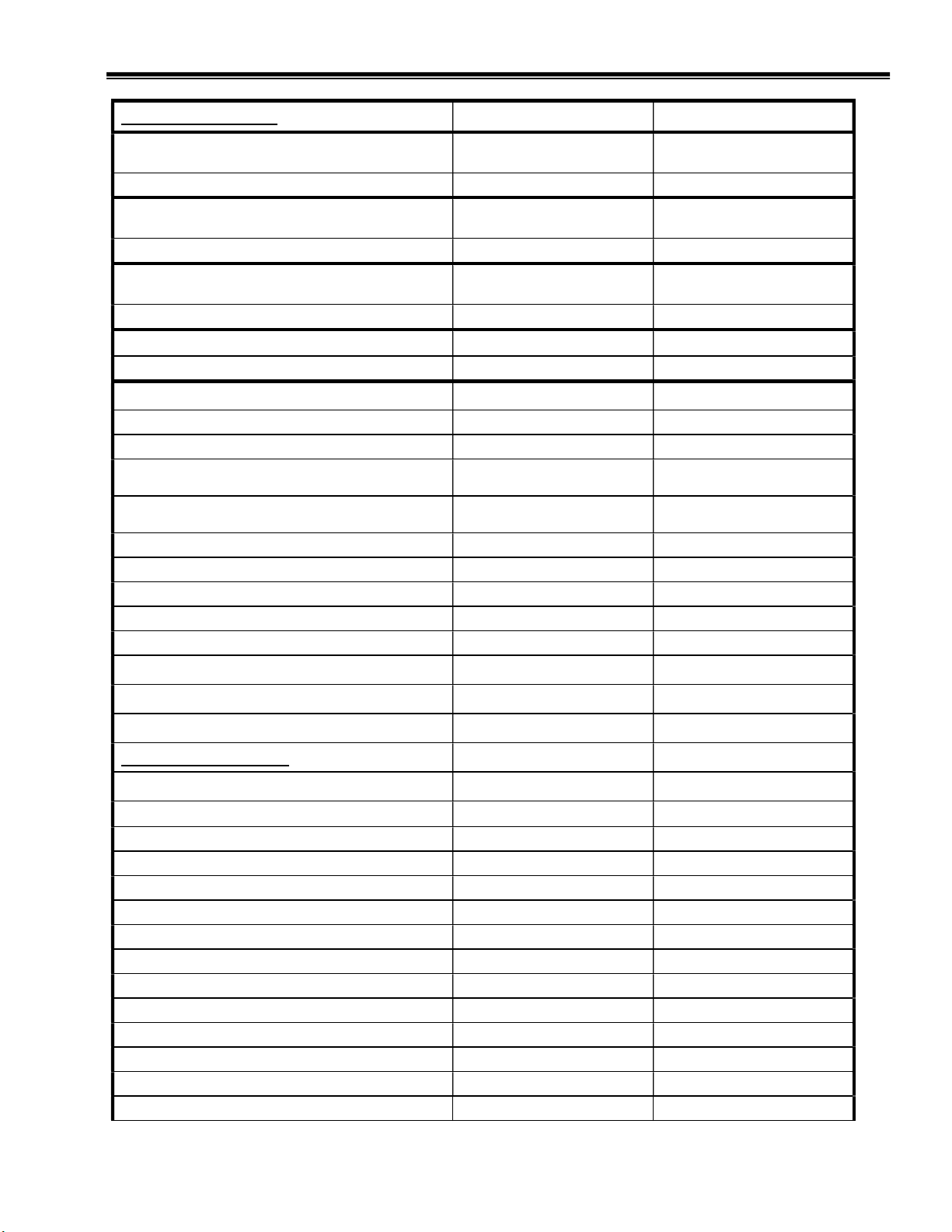
Refrigeration System ECSS40 ECSS60
Condensing Unit Copeland (Self Contained)
Before 8/1/14
30-19128 Obsolete 30-19025 Obsolete
Replacement Compressor 30-19718 30-19719
Condensing Unit Copeland (Self Contained)
After 8/1/14
30-19128 Obsolete 30-20047 Obsolete
Replacement Compressor 30-19718 30-20290
Condensing Unit (Self Contained) Before
2/1/16
30-17889 30-20448
Replacement Compressor 30-18054 30-20290
Condensing Unit (Self Contained) After 2/1/16 30-17889 30-20448
Replacement Compressor 30-18054 30-20290
Safety Pressure Control before 8/1/14 32-51009 32-51009
Safety Pressure Control after 8/1/14 32-51009 N/A
Evaporator Coil Left/ Right 33-18810-L/33-18810-R 33-19285-L/33-19285-R
Expansion Valve TXV (Self Contained Before
12/1/19)
Expansion Valve TXV (Self Contained After
12/1/19)
32-19408 32-19408
32-20874 32-20874
Remote EEV 32-21226 32-21226
Sight Glass 32-54011 32-54011
Refrigerant Filter/Drier 32-19067 32-19067
Refrigeration Solenoid Valve (Remote) 32-14325 32-14325
Refrigeration Solenoid Valve COIL (Remote) 41-14324 41-14324
Motor Evaporator Fan 41-19070 41-19070
Wire Harness Evaporator Motor 43-19083 43-19083
Blade Evaporator Fan 72-12254 72-12254
Electrical Components
Wire Harness 43-21207 43-21206
LED light bar (8) Before 8/1/18 42-19038 42-19038
LED light bar 10" (1) Before 8/1/18 42-19038-1 42-19038
Shelf Lamp Cord Before 8/1/18 43-19061-1 43-19061-1
Light power Supply 12V Before 8/1/18 39-19039 39-19039
LED Strip Light 3500K (8) After 8/1/18 42-20871-25C35 42-20871-42C35
LED Strip Light 3500K 18" (1) After 8/1/18 42-20871-18C35 42-20871-18C35
Shelf Lamp Cord After 8/1/18 43-20861-1B 43-20861-1B
TOP Lamp Cord After 8/1/18 43-20867-1B 43-20867-1B
Light power Supply 24V After 8/1/18 39-20555 39-20555
Shelf Lamp Socket 43-19060-1 43-19060-1
Power Switch 41-13733 41-13733
Light Switch 41-11066 41-11066
Temp Control - Self Contained (Before 32-19027 Obsolete 32-19027 Obsolete
ECSS E3335
Page 35
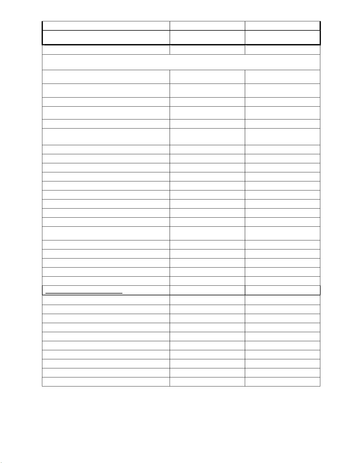
- 35 -
5/23/12) replaced by 32-19865-3
Temp Control Display (Before 5/23/12)
obsolete no longer available
ECSS40 ECSS60
32-19092 Obsolete 32-19092 Obsolete
PARTS LIST CONTINUED
Temp Control - Self Contained (After 5/23/12)
obsolete replaced by 32-19865-3
Temp Control Display (Between 5/23/12 5/1/18) obsolete no longer available
Temp Control - Self Contained (After 5/1/18) 32-19865-3 32-19865-3
Temp Control - Remote (Between 5/23/12 - 5/1/18)
Obsolete replaced by 32-19865-71
Temp Control - Remote (After 5/1/18) 32-19865-71 32-19865-71
Ribbon Cable - Display (Before 5/1/18)
no longer available
Probe Temp (2) 32-19094 32-19094
Timer, Max Run (Before 5/23/12) 41-17324 41-17324
Condensate Pan Ass'y SA4889-1 SA4889-1
Heater Condensate Pan 40-17861 40-17861
Condensate Evap Pan 47-12963 47-12963
High-Temp Safety Ass'y SA-1880 SA-1880
Float Switch Condensate Pan 41-13022 41-13022
Float Condensate Pan SA2928 SA2928
Optional Power Cord 43-19090 43-19090
Optional Field Installed Condensate Pan
120V/1600W
Optional Condensate Pump 230V 47-15687 47-15687
Optional Condensate Pump 120V 47-15686 47-15686
EEV Control 32-21223 32-21223
EEV Temperature Probe 32-21224 32-21224
EEV Pressure Transducer 32-21225 32-21225
Miscellaneous Components
Display Deck Plastic Left/Right 15-18857-L/ 15-18857-R 15-19293-L/ 15-19293-R
Fastener Pad Set Display Deck 77-17848/77-17849 77-17848/77-17849
Metal Shelf (SHELF ONLY) Before 8/1/18 SA4737-L/SA4737-R SA5048-L/SA5048-R
Metal Shelf (SHELF ONLY) After 8/1/18 M20957-3L & 3R M20957-2L & 2R
Air Diffuser Honeycomb Air Discharge W11533-2 W11533-4
Shelf Bracket Long 67-18727 67-18727
Shelf Bracket Short 67-18727-1 67-18727-1
Thermometer 32-13662 32-13662
Replacement Optional Condenser Air Filter 16-19228 16-19228
Super Filter Coat – Filter Adhesive 22-21164 22-21164
32-19445-3 Obsolete 32-19445-3 Obsolete
32-19446 Obsolete 32-19446 Obsolete
32-19446-71 Obsolete 32-19446-71 Obsolete
32-19093 Obsolete 32-19093 Obsolete
47-19541 47-19541
ECSS E3335
Page 36
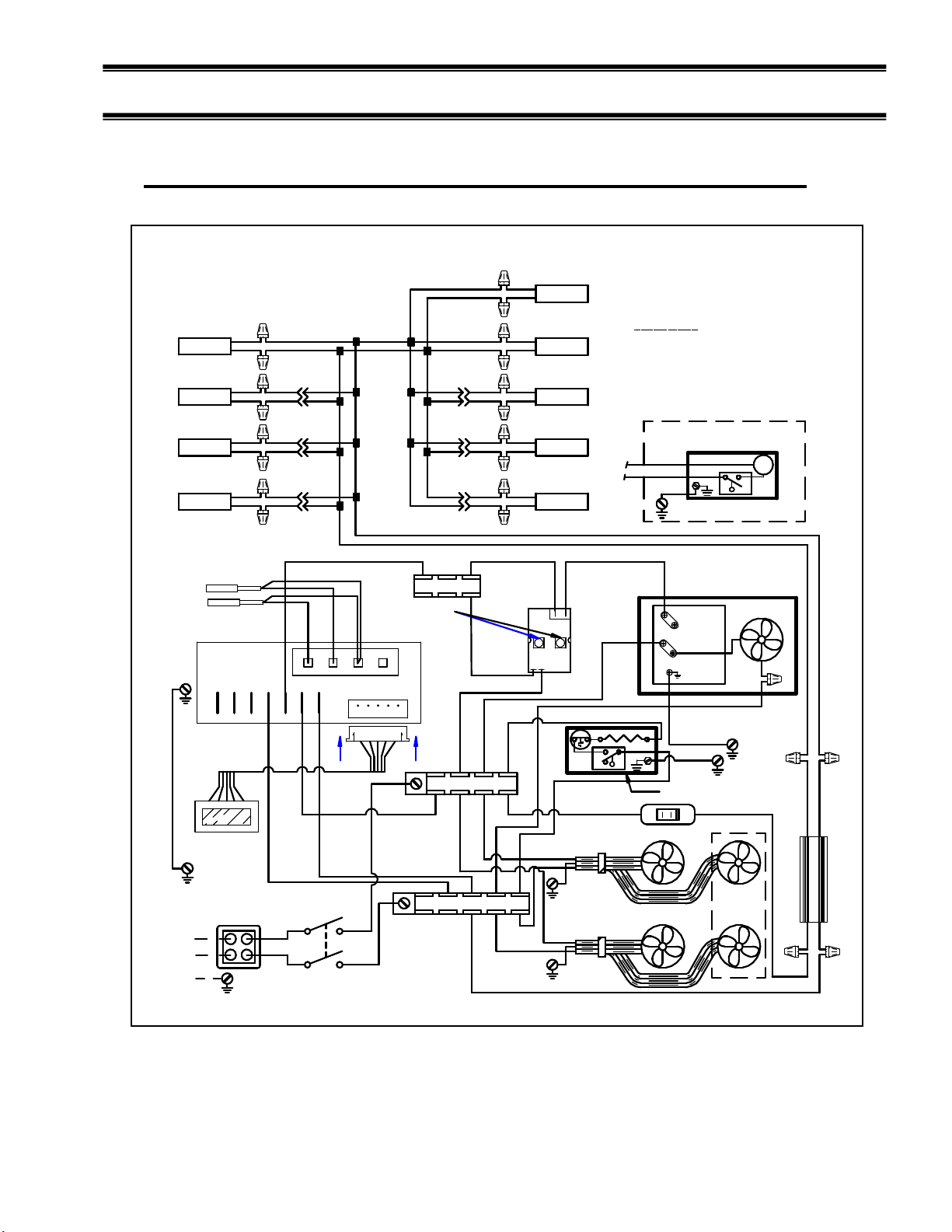
- 36 -
Case Wiring Diagrams
Self-Contained ECSS40 SC Copeland BEFORE 5/23/12
91-19099 10/21/11
ECSS40 SC
R
B
SHELF LAMP
SHELF LAMP
SHELF LAMP
R
B
R
B
R
SHELF LIGHT QUANITY MAY VARY
ON DIFFERENT MODELS.
DEFROST PROBE PB2
TEMP PROBE PB1
1 2 3 4 5 6 7
G(26)
RIBBON
CABLE
DISPLAY
B
B/BL
R
BL
B
B/BL
R
BL
B
B/BL
R
BL
B
8 9 10 11
Y(6)
TURN FULL
CLOCK WISE
R(12)
B/BL
B
B/BL
BBLK
B/BL
R
BL
B
B/BL
R
BL
B
BL
B
B/BL
R
TERM BLOCK
Y (21)
TERM BLOCK L2
R(20)
Y(9)
B
R
BB B/BL B/BL
R
B
R
B
R
R
B
TOP LAMP
TOP LAMPTOP LAMP
SHELF LAMP
SHELF LAMP
SHELF LAMP
4
1
32
B(17)
B(22)
MAX RUN TIMER
R(23)
NO
NC
COLOR CODE
B = BLACK
W = WHITE
BL = BLUE
Y = YELLOW
IF OPTIONAL CONDENSATE PUMP OR
CONDENSATE PAN ARE NOT USED
DISCARD WIRES B(22), R(23),G(24),
OPTIONAL
CONDENSATE PUMP
R(22)
R(23)
P
G(24)
B/BL
Y(10)
1 or L1
COND UNIT
R(11)
C
R or L2
GR
G(25)
G(24)
B
B(17)
CONDENSATE PAN
R(15)R(14)
LIGHT SWITCH
G = GREEN
R = RED
FAN
B
12V
B/BL
B
R
B(5)
208-240V / 60Hz / 1PH
L2
L1
N
R(2)
B(1)
POWER SWITCH
B(13)
R(4)
B(3)
TERM BLOCK L1
RIB
RIB
EVAPORATOR FANS
IMSS
MODELS
ONLY
R(15)
B(16)
POWER SUPPLY
BL
BRW
ECSS E3335
Page 37
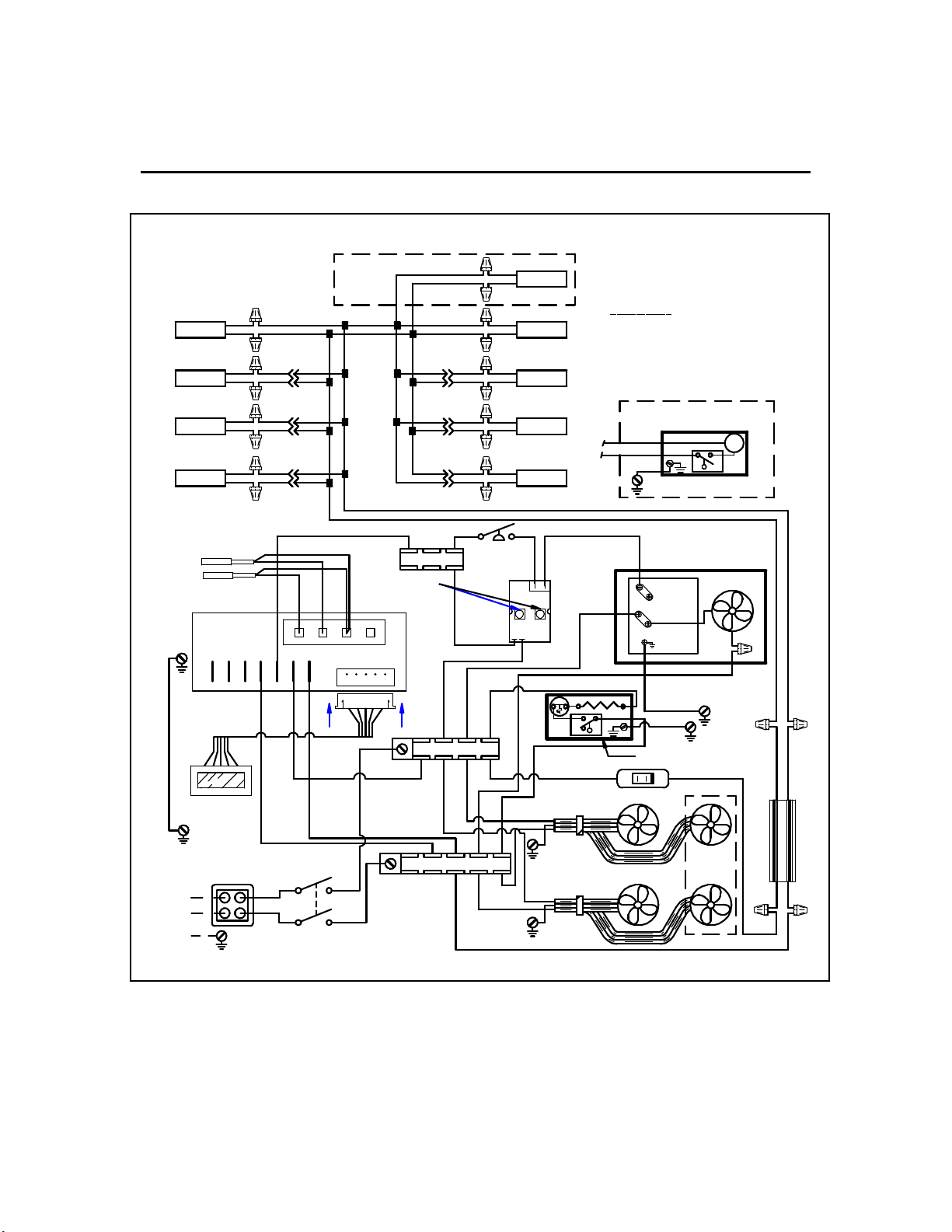
- 37 -
Self-Contained ECSS40 SC Tecumseh BEFORE 5/23/12
91-19504 11/16/11
ECSS40 SC
R
B
R
B
SHELF LAMP
SHELF LAMP
R
B
R
SHELF LIGHT QUANITY MAY VARY
ON DIFFERENT MODELS.
DEFROST PROBE PB2
TEMP PROBE PB1
1 2 3 4 5 6 7
B BBLK
B/BL
R
BL
B
B/BL
R
BL
B
B/BL
R
BL
B
8 9 10 11
ECSS
MODELS
ONLY
Y(6)
B/BL
B/BL
B
B/BL
TERM BLOCK
TURN FULL
CLOCK WISE
B/BL
B
B/BL
B
B
B
TOP LAMP
R
BB B/BL B/BL
TOP LAMPTOP LAMP
R
R
B
BL
R
BL
BL
R
Y
R
B
R
R
B
SHELF LAMPSHELF LAMP
SHELF LAMP
SHELF LAMP
Y
COLOR CODE
B = BLACK
W = WHITE
BL = BLUE
Y = YELLOW
G = GREEN
R = RED
IF OPTIONAL CONDENSATE PUMP OR
CONDENSATE PAN ARE NOT USED
DISCARD WIRES B(22), R(23),G(24),
OPTIONAL
CONDENSATE PUMP
R(22)
R(23)
P
G(24)
B/BL
Y(10)
PRESS
Y (21)
SWITCH
R(20)
41
R(11)
32
MAX RUN TIMER
R(23)
1 or L1
R or L2
G(25)
GR
B(17)
COND UNIT
B
FAN
G(26)
RIBBON
CABLE
DISPLAY
B(5)
208-240V / 60Hz / 1PH
L2
L1
N
R(2)
B(1)
POWER SWITCH
TERM BLOCK L2
R(12)
B(13)
TERM BLOCK L1
R(4)
B(3)
RIB
RIB
B(17)
NO
C
NC
B(22)
G(24)
CONDENSATE PAN
R(15)R(14)
LIGHT SWITCH
EVAPORATOR FANS
IMSS
MODELS
ONLY
12V
R(15)
B(16)
ECSS E3335
B B/BLBR
POWER SUPPLY
BL
BRW
Page 38
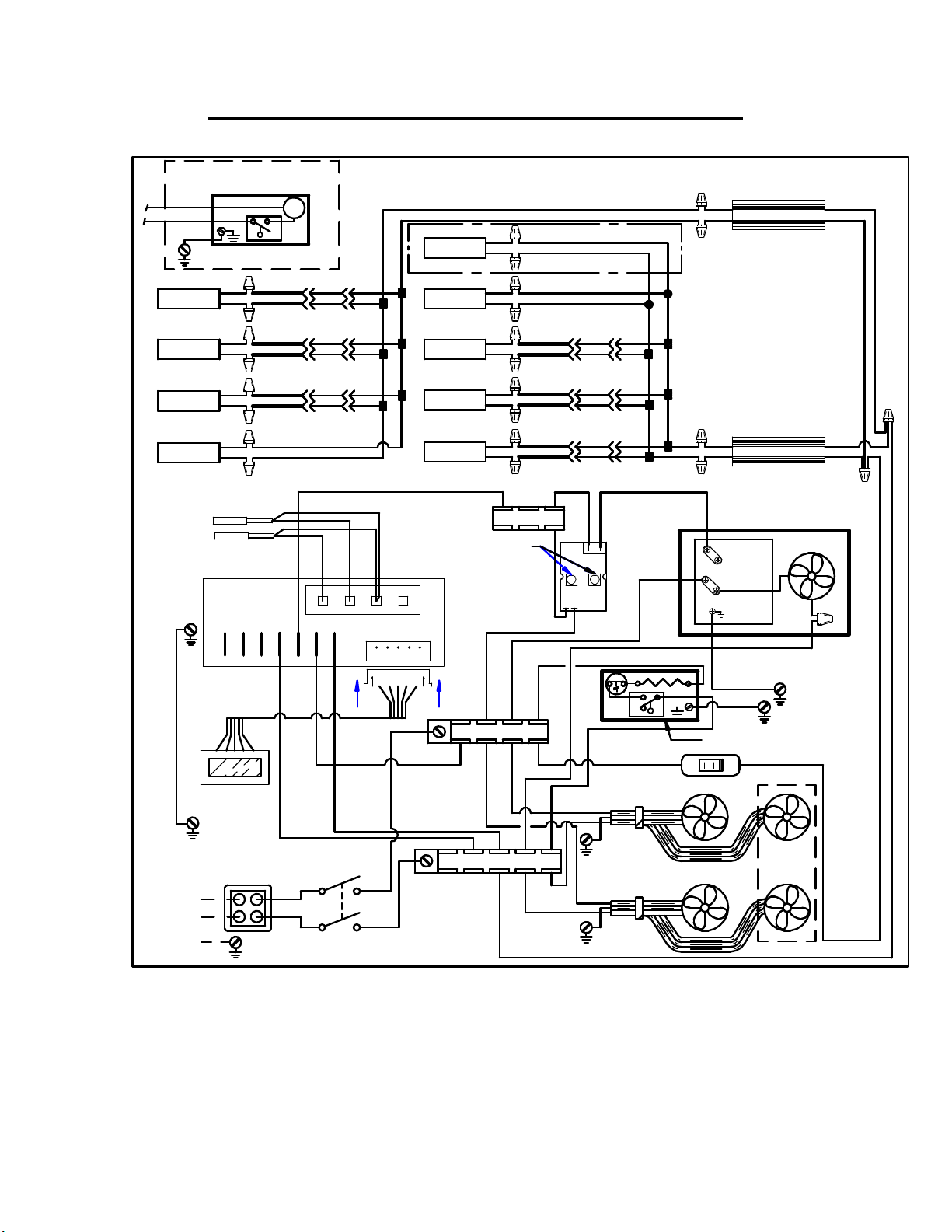
- 38 -
Self-Contained ECSS60SC BEFORE 5/23/12
OPTIONAL
CONDENSATE PUMP
R(22)
R(23)
G(24)
B
SHELF LAMP
SHELF LAMP
SHELF LAMP
TOP LAMP
BL
R
B
BL
R
B
R
BL
R
B
R
DEFROST PROBE PB2
TEMP PROBE PB1
1 2 3 4 5 6 7
IF OPTIONAL CONDENSATE PUMP OR
CONDENSATE PAN ARE NOT USED
DISCARD WIRES B(22), R(23),G(24),
P
B/BLR
B/BL
B
B/BLR
B/BL
B
B/BL
B/BL
B
B/BL
8 9 10 11
91-19453 12/19/11 IMSS60SC & ECSS60SC
B
B/BL
B/BL
B
B/BL
B
B/BL
B
B/BL
B
B/BL
B
B/BL
B
B/BLR
B
B/BL
B
Y(10)
TOP LAMP
B
B
B
B
TOP LAMP
SHELF LAMP
SHELF LAMP
SHELF LAMP
Y(6)
B
R
B
R
B
R
B
R
B
R
ECSS ONLY
R
BL
BL
R
BL
Y(9)
TERM BLOCK
TURN FULL
TURN FULL
CLOCK WISE
CLOCK WISE
4
1
Y (21)
32
R(11)
MAX RUN TIMER
R(20)
R(23)
R
B
COLOR CODE
B = BLACK
W = WHITE
G = GREEN
B
B/BL
B
R
G(25)
POWER SUPPLY
POWER SUPPLY
1 or L1
R or L2
GR
BL = BLUE
Y = YELLOW
R = RED
COND UNIT
B
B(17)
BRW
BL
BRW
BL
FAN
G(26)
RIBBON
CABLE
DISPLAY
B(5)
208-240V / 60Hz / 1PH
L2
R(2)
B(1)
L1
N
POWER SWITCH
B(13)
R(4)
B(3)
TERM BLOCK L2
R(12)
TERM BLOCK L1
RIB
RIB
B(17)
NO
C
NC
G(24)
B(22)
CONDENSATE PAN
R(15)R(14)
LIGHT SWITCH
IMSS
EVAPORATOR FANS
MODELS
ONLY
R(15)
B(16)
ECSS E3335
Page 39
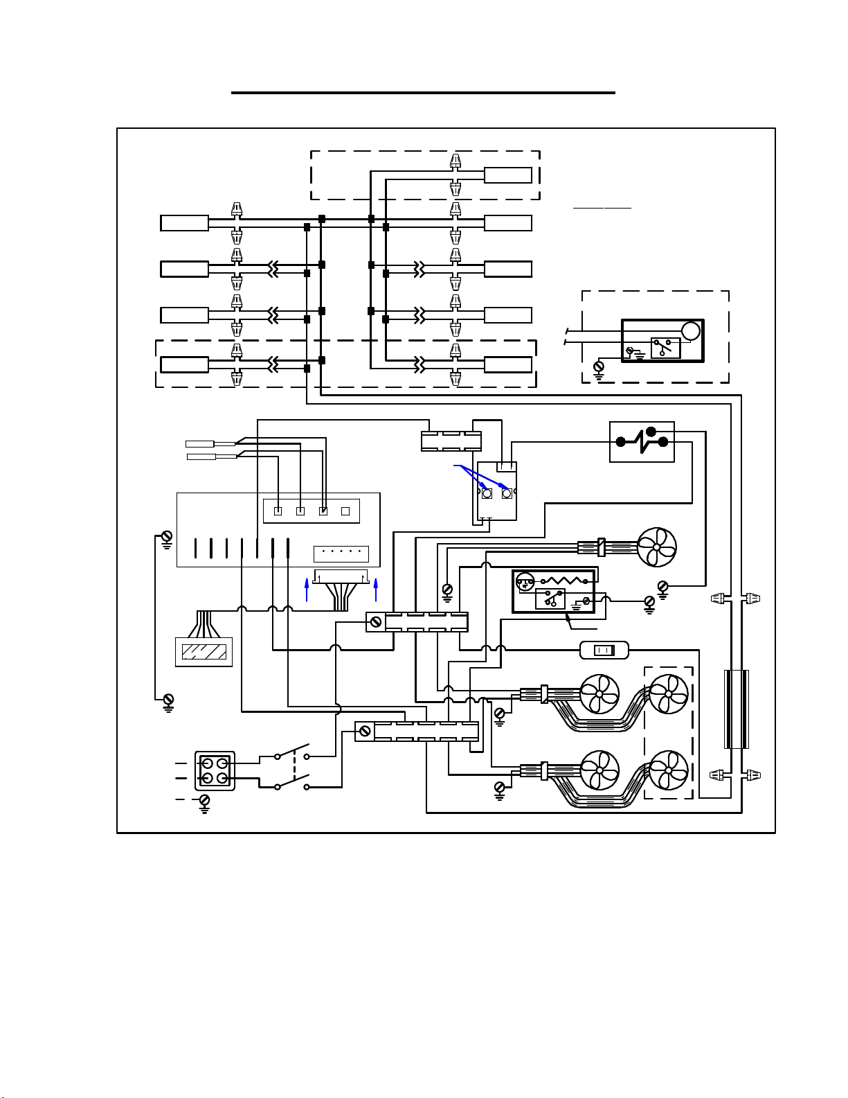
- 39 -
Remote ECSS40R BEFORE 5/23/12
B/BL
B/BL
B/BL
ECSS
MODELS
ONLY
B/BLB/BLB B
BLK BB
B
B
ECSS
B
MODELS
ONLY
91-19155 2/25/11
IMSS/ECSS REMOTE
TOP LAMP TOP LAMP
SHELF LAMP
SHELF LAMP
SHELF LAMP
R
B
R
R
BL
R
B
BL
R
R
B
BL
R
B/BL
B/BL
B
B/BL
B/BL
B
B/BL
R
BL
B
R
BL
B
BL
R
Y(6)
DEFROST PROBE PB2
TEMP PROBE PB1
8 9 10 11
TERM BLOCK
TURN FULL
TURN FULL
CLOCK WISE
CLOCK WISE
R(20)
1 2 3 4 5 6 7
G(26)
RIBBON
CABLE
TERM BLOCK L2
R(12)
DISPLAY
B
R
R
B
R
B
R
R
B
Y(9)
Y (21)
2 3
TOP LAMP
SHELF LAMP
SHELF LAMP
SHELF LAMP
1 4
B(22)
COLOR CODE
B = BLACK
W = WHITE
BL = BLUE
Y = YELLOW
IF OPTIONAL CONDENSATE PUMP OR
CONDENSATE PAN ARE NOT USED
DISCARD WIRES B(22), R(23),G(24),
OPTIONAL
CONDENSATE PUMP
R(22)
R(23)
G(24)
B/BL
Y(10)
REFRIGERATION
R(11)
MAX RUN TIMER
R(23)
NO
C
NC
R(14) R(15)
SOLENOID
BASE FAN
G(24)
CONDENSATE PAN
LIGHT SWITCH
G = GREEN
R = RED
P
G(25)
12V
B
B/BL
B
R
B(5)
208-240V / 60Hz / 1PH
L2
L1
N
R(2)
B(1)
POWER SWITCH
B(13)
R(4)
B(3)
TERM BLOCK L1
RIB
RIB
EVAPORATOR FANS
IMSS
MODELS
ONLY
R(15)
B(16)
POWER SUPPLY
BL
BRW
ECSS E3335
Page 40
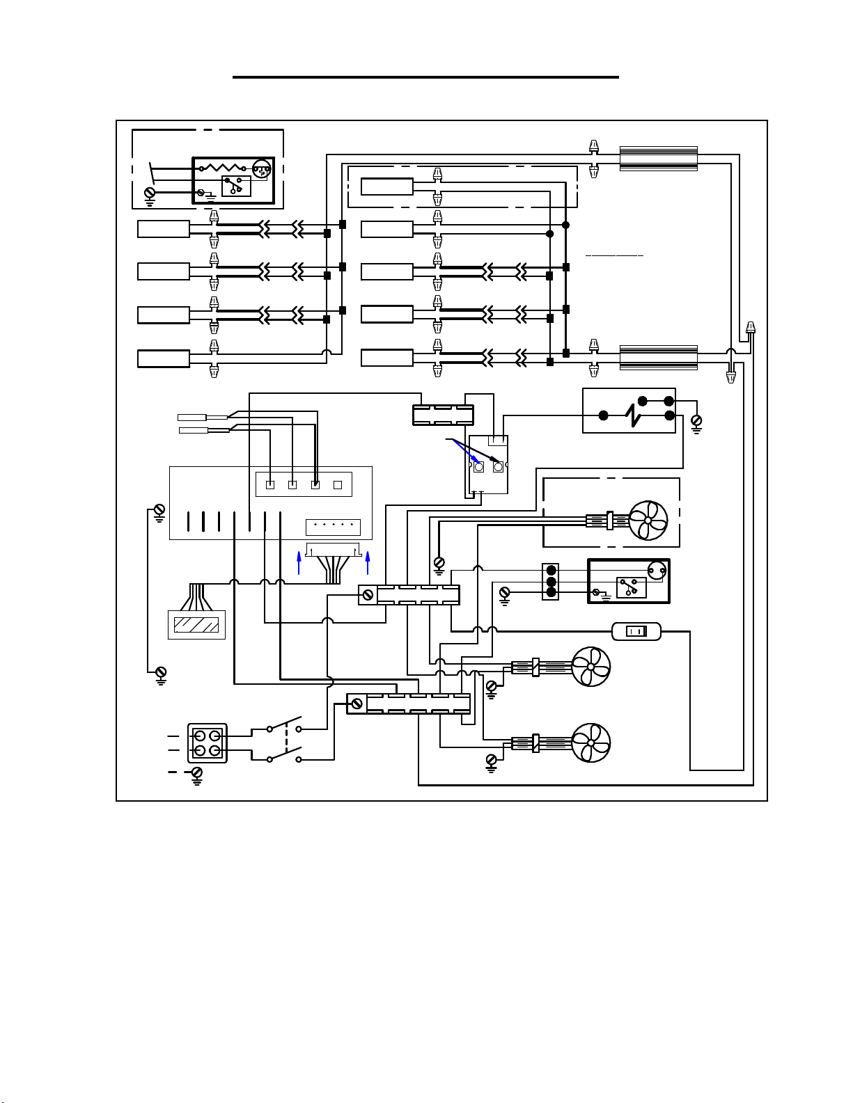
- 40 -
Remote ECSS60R BEFORE 5/23/12
OPTIONAL CONDENSATE
HEATER PAN
R(23)
B(22)
G(24)
SHELF LAMP
SHELF LAMP
SHELF LAMP
TOP LAMP
C
B
R
B
R
B
R
B
R
DEFROST PROBE PB2
TEMP PROBE PB1
1 2 3 4 5 6 7
NO
NC
B/BL
R
BL
R
BL
R
BL
B
B/BL
B
B/BL
B
8 9 10 11
B/BL
B
B/BL
B
B/BL
B
B/BL
B
TOP LAMP
TOP LAMP
SHELF LAMP
SHELF LAMP
SHELF LAMP
Y(6)
TURN FULL
TURN FULL
CLOCK WISE
CLOCK WISE
B
B/BL
B
R
B
R
B
R
BL
R
B
R
BL
R
B
BL
R
TERM BLOCK
R(20)
91-19454 1/2/12 IMSS60R & ECSS60R
R
POWER SUPPLY
B
COLOR CODE
B = BLACK
W = WHITE
G = GREEN
BRW = BROWN
B/BL
B
B
BL = BLUE
Y = YELLOW
R = RED
POWER SUPPLY
R
JUMP R & Y
BL
REFRIGERATION
SOLENOID
G
B
ECSS ONLY
Y(9)
Y (21)
32
B/BL
B/BL
B/BL
41
B/BL
B
B/BL
B
B/BL
B
B
B/BL
B
B
B/BLR
B
B
Y(10)
R(11)
BASE FAN OPTIONAL
MAX RUN TIMER
BRW
BL
BRW
BL
G(25)
G(26)
RIBBON
CABLE
DISPLAY
208-240V / 60Hz / 1PH
L2
L1
N
B(5)
B(13)
R(2)
B(1)
POWER SWITCH
R(4)
B(3)
R(12)
TERM BLOCK L1
TERM BLOCK L2
RIB
RIB
RIB
R(23)
B(22)
G(24)
BRW
BL
G
CONDENSATE
NO
C
PUMP
NC
R(15)R(14)
LIGHT
SWITCH
EVAPORATOR FANS
R(15)
B(16)
ECSS E3335
Page 41
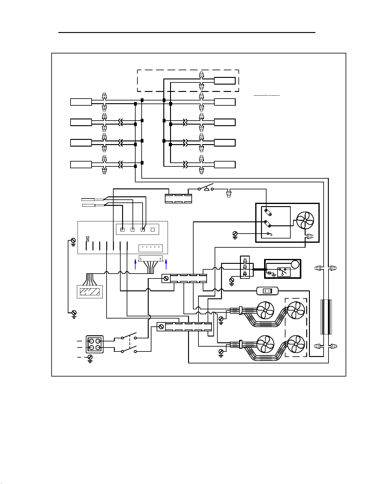
- 41 -
Self-Contained ECSS40 SC Tecumseh Between 5/23/12-5/1/18
91-19504 8/26/14
ECSS40SC TECHUMSEH
R
B
R
SHELF LAMP
SHELF LAMP
B
R
B
R
SHELF LIGHT QUANITY MAY VARY
ON DIFFERENT MODELS.
DEFROST PROBE PB2
TEMP PROBE PB1
1 2 3 4 5 6 7
G(26)
RIBBON
CABLE
DISPLAY
B BBLK
B/BL
R
BL
B
B/BL
R
BL
B
B/BL
R
BL
B
B
8 9 10 11
B
ECSS
MODELS
ONLY
Y(6)
W
W
TERM BLOCK
TERM BLOCK L2
R(12)
B
B/BL
B/BL
B/BL
B/BL
B
B/BL
B
B
B
TOP LAMP
R
BB B/BL B/BL
TOP LAMPTOP LAMP
R
R
B
BL
R
BL
BL
R
Y
R
B
R
R
B
SHELF LAMPSHELF LAMP
SHELF LAMP
SHELF LAMP
Y
COLOR CODE
B = BLACK
W = WHITE
IF OPTIONAL CONDO PUMP HOSE
HEATER IS USED, TIE HEATER
WIRES TO B22 & R23
B/BL
BL = BLUE
Y = YELLOW
Y(10)
G = GREEN
R = RED
PRESS
SWITCH
B(22)
R(23)
G(24)
R(11)
G(25)
B(17)
2 X 4
BR
BL
G
LIGHT SWITCH
1 or L1
R or L2
GR
CONDENSATE PUMP
COND UNIT
B
P
R(15)R(14)
FAN
12V
B
B/BL
B
R
B(5)
208-240V / 60Hz / 1PH
L2
L1
N
R(2)
B(1)
POWER SWITCH
B(13)
R(4)
B(3)
TERM BLOCK L1
RIB
RIB
EVAPORATOR FANS
IMSS
MODELS
ONLY
R(15)
B(16)
POWER SUPPLY
BL
BRW
ECSS E3335
Page 42
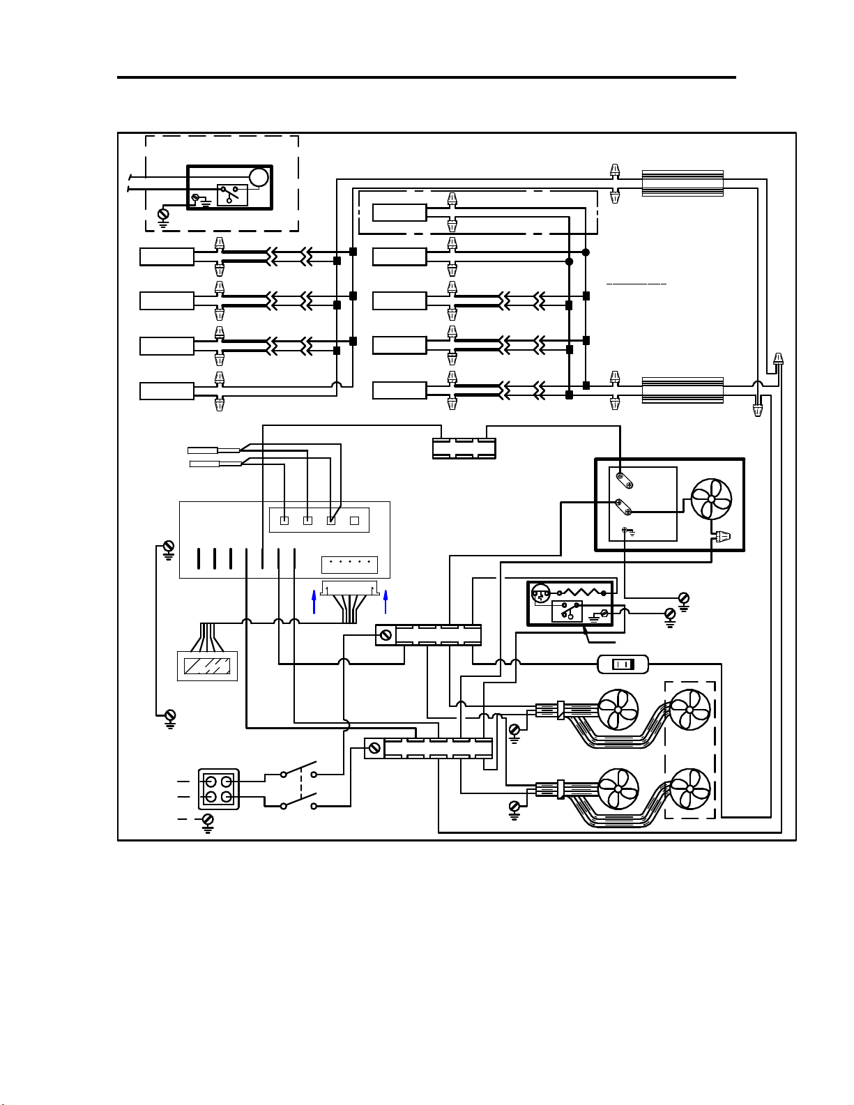
- 42 -
Self-Contained ECSS60SC used Between 5/23/12 & 8/1/14
OPTIONAL
CONDENSATE PUMP
R(22)
R(23)
G(24)
B
BL
SHELF LAMP
SHELF LAMP
SHELF LAMP
TOP LAMP
R
B
BL
R
B
R
BL
R
B
R
DEFROST PROBE PB2
TEMP PROBE PB1
IF OPTIONAL CONDENSATE PUMP OR
CONDENSATE PAN ARE NOT USED
DISCARD WIRES B(22), R(23),G(24),
P
B/BLR
B/BL
B
B
B/BLR
B/BL
B
B
B/BL
B/BL
B
B
B/BL
B
B
B
8 9 10 11
91-19630 5/23/12 IMSS60SC & ECSS60SC
B
B/BL
B/BL
B
B/BL
B
B/BL
B
B/BL
B
B/BL
B
B/BL
B
B/BL
B
B/BL
B
Y(10)
TOP LAMP
TOP LAMP
SHELF LAMP
SHELF LAMP
SHELF LAMP
Y(6)
B
R
B
R
B
R
B
R
B
R
ECSS ONLY
R
BL
R
BL
R
BL
TERM BLOCK
W
W
R(11)
R
B
COLOR CODE
B = BLACK
W = WHITE
G = GREEN
B
B/BL
B
R
POWER SUPPLY
POWER SUPPLY
1 or L1
R or L2
GR
BL = BLUE
Y = YELLOW
R = RED
COND UNIT
B
BRW
BL
BRW
BL
FAN
1 2 3 4 5 6 7
G(26)
RIBBON
CABLE
DISPLAY
B(5)
208-240V / 60Hz / 1PH
L2
R(2)
B(1)
L1
N
POWER SWITCH
B(13)
R(4)
B(3)
TERM BLOCK L2
R(12)
TERM BLOCK L1
RIB
RIB
R(23)
B(17)
NO
C
NC
B(22)
CONDENSATE PAN
LIGHT SWITCH
EVAPORATOR FANS
G(25)
B(17)
G(24)
R(15)R(14)
IMSS
MODELS
ONLY
R(15)
B(16)
ECSS E3335
Page 43
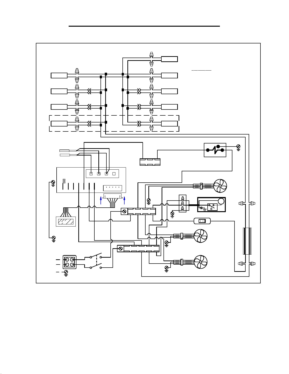
- 43 -
Remote ECSS40R Between 5/23/12-5/1/18
B/BL
B/BL
B/BL
B
B/BL
B
B/BL
R
BL
B
R
BL
B
BL
R
91-19629 5/23/12
ECSS40R
TOP LAMP TOP LAMP
SHELF LAMP SHELF LAMP
SHELF LAMP
SHELF LAMP
R
B
R
B
R
B
R
B/BL
R
BL
B
B/BL
R
BL
B
B/BL
R
BL
B
B/BLB/BLB B
BLK BB
ECSS
MODELS
ONLY
Y(6)
DEFROST PROBE PB2
TEMP PROBE PB1
1 2 3 4 5 6 7
G(26)
RIBBON
B
B
W
8 9 10 11
W
TERM BLOCK
CABLE
TERM BLOCK L2
R(12)
DISPLAY
B
R
R
B
R
B
R
R
B
TOP LAMP
SHELF LAMP
SHELF LAMP
B(22)
R(23)
G(24)
COLOR CODE
B = BLACK
W = WHITE
IF OPTIONAL CONDO PUMP HOSE
HEATER IS USED, TIE HEATER
WIRES TO B22 & R23
B/BL
BL = BLUE
Y = YELLOW
Y(10)
REFRIGERATION
R(11)
SOLENOID
BASE FAN
2 X 4
BR
BL
G
CONDENSATE PUMP
R(14) R(15)
LIGHT SWITCH
P
G = GREEN
R = RED
G(25)
12V
B
B/BL
R
B
B(5)
208-240V / 60Hz / 1PH
L2
L1
R(2)
B(1)
N
B(13)
R(4)
B(3)
POWER SWITCH
TERM BLOCK L1
RIB
RIB
EVAPORATOR FANS
R(15)
B(16)
POWER SUPPLY
BL
BRW
ECSS E3335
Page 44
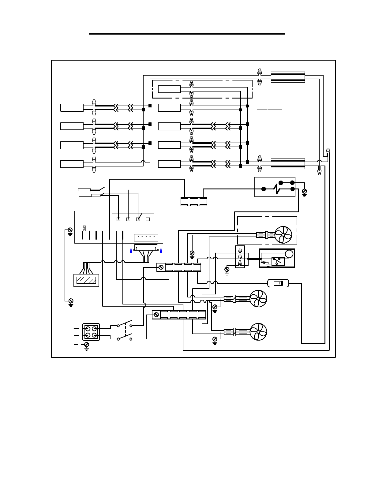
- 44 -
SHELF LAMP
SHELF LAMP
SHELF LAMP
Remote ECSS60R Between 5/23/12-5/1/18
91-19631 5/23/12 IMSS60R & ECSS60R
B
B/BL
B/BL
B/BL
B/BL
B
B/BL
B
B/BLR
B
B
B/BLR
B
B
B
TOP LAMP
B
BL
R
B
R
BL
R
B
BL
R
B/BL
B/BL
B/BL
B/BLR
B
B
B/BL
B
B
B/BLR
B
B
TOP LAMP
SHELF LAMP
SHELF LAMP
R
B
R
B
R
B
R
ECSS ONLY
BL
BL
R
POWER SUPPLY
B
COLOR CODE
B = BLACK
W = WHITE
G = GREEN
BRW = BROWN
IF OPTIONAL CONDO PUMP HOSE
HEATER IS USED, TIE HEATER
WIRES TO B22 & R23
BL = BLUE
Y = YELLOW
R = RED
BRW
BL
TOP LAMP
B
R
DEFROST PROBE PB2
TEMP PROBE PB1
8 9 10 11
1 2 3 4 5 6 7
G(26)
RIBBON
CABLE
DISPLAY
B(5)
208-240V / 60Hz / 1PH
L2
L1
N
R(2)
B(1)
POWER SWITCH
B/BL
B/BL
B
SHELF LAMP
B/BLR
B
R
B/BL
BL
B
B
B
B
POWER SUPPLY
R
Y(6)
B
B
W
W
TERM BLOCK
JUMP R & Y
Y(10)
REFRIGERATION
R(11)
BL
SOLENOID
G
B
BRW
BL
G(25)
BASE FAN OPTIONAL
B(13)
R(4)
B(3)
TERM BLOCK L2
R(12)
TERM BLOCK L1
RIB
RIB
RIB
B(22)
R(23)
G(24)
BR
BL
G
2 X 4
CONDENSATE PUMP
EVAPORATOR FANS
P
R(15)R(14)
LIGHT
SWITCH
R(15)
B(16)
ECSS E3335
Page 45
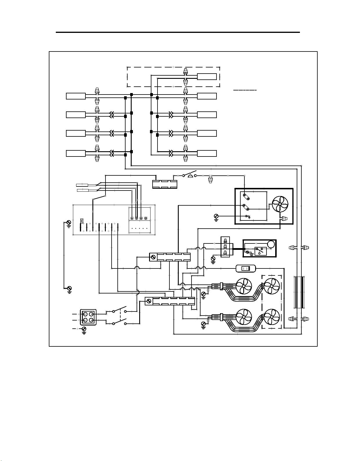
- 45 -
Self-Contained ECSS40SC -Between 5/1/18 & 12/15/18
91-19504-1 5/1/18
ECSS40SC TECHUMSEH
R
B
R
SHELF LAMP
SHELF LAMP
B
R
B
R
SHELF LIGHT QUANITY MAY VARY
ON DIFFERENT MODELS.
DEFROST PROBE PB2
TEMP PROBE PB1
5 4 6 7
G(26)
B BBLK
B/BL
R
BL
B
B/BL
R
BL
B
B/BL
R
BL
B
B
ECSS
MODELS
ONLY
Y(6)
W
W
B
8 9 10 11
R(12)
B/BL
B/BL
B
B/BL
TERM BLOCK
B
TERM BLOCK L2
B/BL
B
B/BL
B
B
B
TOP LAMP
R
BB B/BL B/BL
TOP LAMPTOP LAMP
R
R
B
BL
R
BL
BL
R
Y
SHELF LAMPSHELF LAMP
R
B
SHELF LAMP
R
R
B
SHELF LAMP
Y
COLOR CODE
B = BLACK
W = WHITE
IF OPTIONAL CONDO PUMP HOSE
HEATER IS USED, TIE HEATER
WIRES TO B22 & R23
B/BL
BL = BLUE
Y = YELLOW
Y(10)
G = GREEN
R = RED
PRESS
SWITCH
B(22)
R(23)
G(24)
R(11)
G(25)
B(17)
2 X 4
BR
BL
G
LIGHT SWITCH
1 or L1
R or L2
GR
CONDENSATE PUMP
COND UNIT
B
P
R(15)R(14)
FAN
12V
B
B B/BL
R
B(5)
208-240V / 60Hz / 1PH
L2
L1
N
R(2)
B(1)
POWER SWITCH
B(13)
R(4)
B(3)
TERM BLOCK L1
RIB
RIB
EVAPORATOR FANS
IMSS
MODELS
ONLY
R(15)
B(16)
ECSS E3335
POWER SUPPLY
BL
BRW
Page 46
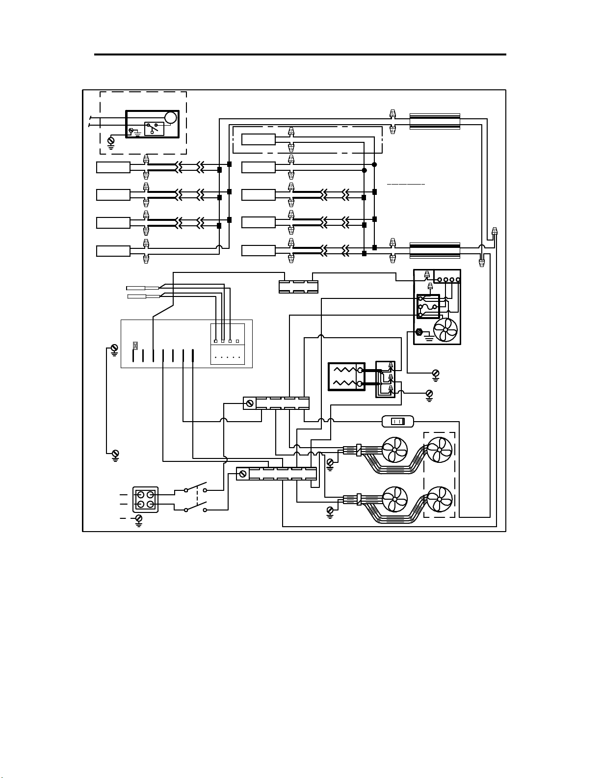
- 46 -
Self-Contained ECSS60SC -Between 5/1/18 & 12/15/18
CONDENSATE PUMP
B(22)
R(23)
G(24)
CONDENSATE PUMP
STD ECSS
B
BL
SHELF LAMP
SHELF LAMP
SHELF LAMP
TOP LAMP
R
B
BL
R
B
R
BL
R
B
R
DEFROST PROBE PB2
TEMP PROBE PB1
5 4 6 7
G(26)
IF OPTIONAL CONDO PUMP HOSE
HEATER IS USED, TIE HEATER
WIRES TO B22 & R23
P
B/BLR
B/BL
B
B
B/BLR
B/BL
B
B
B/BL
B/BL
B
B
B/BL
B
W
B
8 9 10 11
W
R(12)
B
TOP LAMP
TOP LAMP
SHELF LAMP
SHELF LAMP
SHELF LAMP
Y(6)
91-20308-1 5/1/18 IMSS60SC & ECSS60SC SCROLL
B/BL
B
R
B
R
B
R
B
R
B
R
TERM BLOCK
TERM BLOCK L2
B
ECSS ONLY
R
BL
BL
R
BL
R(23)
B/BL
B
B/BL
B
B/BL
B/BL
B
B
B/BLR
B/BL
B
B
B/BL
B/BL
B
B
B(17)
R(11)
CONDENSATE
PAN STD IMSS
B(22)
B/BL
B
Y(10)
2X4
BL
BR
G
LIGHT SWITCH
R
POWER SUPPLY
B
COLOR CODE
B = BLACK
W = WHITE
G = GREEN
B
POWER SUPPLY
R
L2
L1
G(25)
G(24)
BRW
BL
BL = BLUE
Y = YELLOW
R = RED
BRW
BL
1
453
PRESS
CONTROL
CONDENSING
UNIT
R(15)R(14)
B(5)
208-240V / 60Hz / 1PH
L2
L1
R(2)
B(1)
N
B(13)
R(4)
B(3)
POWER SWITCH
TERM BLOCK L1
RIB
RIB
EVAPORATOR FANS
IMSS
MODELS
ONLY
R(15)
B(16)
ECSS E3335
Page 47
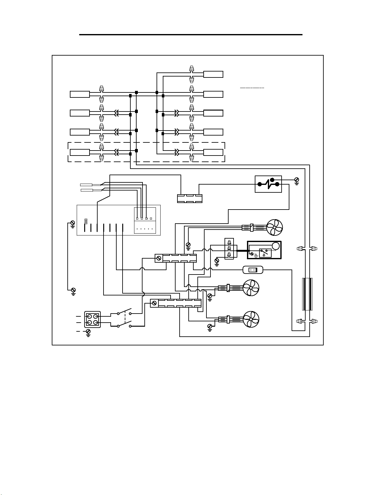
- 47 -
Remote ECSS40R - Between 5/1/18 & 12/15/18
91-19629-1 5/1/18
ECSS40R
B B
TOP LAMP TOP LAMP
SHELF LAMP SHELF LAMP
SHELF LAMP
SHELF LAMP
R
B
R
B
R
B
R
B/BL
R
BL
B
B/BL
R
BL
B
B/BL
R
BL
B
B/BLB/BL
BLK BB
ECSS
MODELS
ONLY
B
B/BL
B/BL
B/BL
B/BL
B
B/BL
R
BL
B
R
BL
B
BL
R
Y(6)
DEFROST PROBE PB2
TEMP PROBE PB1
5 4 6 7
B
W
W
B
TERM BLOCK
G(26)
R(12)
B
R
R
B
R
B
SHELF LAMP
R
R
SHELF LAMP
B
TOP LAMP
B(22)
R(23)
G(24)
COLOR CODE
B = BLACK
W = WHITE
IF OPTIONAL CONDO PUMP HOSE
HEATER IS USED, TIE HEATER
WIRES TO B22 & R23
B/BL
BL = BLUE
Y = YELLOW
Y(10)
REFRIGERATION
R(11)
SOLENOID
BASE FAN
2 X 4
BR
BL
G
CONDENSATE PUMP
R(14) R(15)
LIGHT SWITCH
P
G = GREEN
R = RED
G(25)
12V
B
B/BLB
R
B(5)
208-240V / 60Hz / 1PH
L2
L1
R(2)
B(1)
N
B(13)
R(4)
B(3)
POWER SWITCH
TERM BLOCK L1
RIB
RIB
EVAPORATOR FANS
R(15)
B(16)
POWER SUPPLY
BL
BRW
ECSS E3335
Page 48
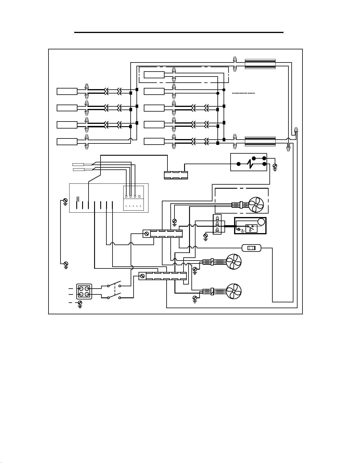
- 48 -
Remote ECSS60R - Between 5/1/18 & 12/15/18
91-19631- 1 IMSS60R & ECSS60R - AFTER 5/1/18
SHELF LAMP
SHELF LAMP
SHELF LAMP
B
B/BL
B/BL
B/BL
B/BL
B
B/BL
B
B/BLR
B
B
B/BLR
B
B
TOP LAMP
B
BL
R
B
BL
R
B
BL
R
B/BL
B/BL
B/BL
B/B LR
B
B
B/B LR
B
B
B/B LR
B
B
TOP LAMP
SHELF LAMP
SHELF LAMP
B
R
B
R
B
R
B
R
ECSS ONLY
BL
BL
R
B
COLOR CODE
B = BLACK
W = WHITE
G = GREEN
BRW = BROWN
IF OPTIONAL CONDO PUMP HOSE
HEATER IS USED, TIE HEATER
WIRES TO B22 & R23
POWER SUPPLY
BL = BLUE
Y = YELLOW
R = RED
BRW
BL
TOP LAMP
B
R
DEFROST PROBE PB2
TEMP PROBE PB1
5 4 6 7
G(26)
B(5)
208-240V / 60Hz / 1PH
L2
L1
N
R(2)
B(1)
POWER SWITCH
B/B L
8 9 10 11
B(13)
R(4)
B(3)
B
SHELF LAMP
B
R
B/BL
BL
B
B
B
POWER SUPPLY
B
B/BL
B/BLR
R
Y(6)
B
W
W
B
TERM BLOCK
JUMP R & Y
Y(10)
REFRIGERATION
R(11)
BL
SOLENOID
G
B
BRW
BL
G(25)
BASE FAN OPTIONAL
RIB
TERM BLOCK L2
R(12)
TERM BLOCK L1
B(22)
R(23)
G(24)
RIB
RIB
BR
BL
G
2 X 4
CONDENSATE PUMP
EVAPORATOR FANS
P
R(15)R(14)
LIGHT
SWITCH
R(15)
B(16)
ECSS E3335
Page 49
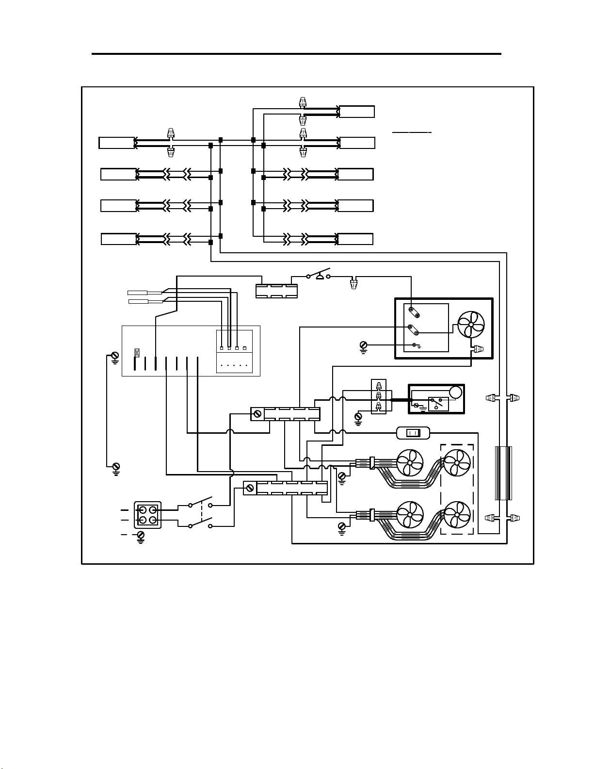
- 49 -
Self-Contained ECSS40SC Between 12/15/18 & 12/1/19
91-19504-2 12/27/18
ECSS40SC ITC LED
TOP LAMP
SHELF LAMP
SHELF LAMP
SHELF LAMP
+B(RI B)
+B(RI B)
- B
+B(RI B)
- B
+B(RI B)
- B
- B
SHELF LIGHT QUANITY MAY VARY
ON DIFFERENT MODELS.
DEFROST PROBE PB2
TEMP PROBE PB1
5 4 6 7
G(26)
B/R
B/BL B/BL
B/R
B/R
B/BL
B/BL
B/R
B/R
B/BL
B/BL
B/R B/R
B/R
B/BL
B/BL
B
Y(6)
W
W
B
8 9 10 11
R(12)
B/R
B/BL
B/R
B/BL
B/BL
TERM BLOCK
B
TERM BLOCK L2
B/R
B/BL
B/RB/R
B/BL
B/R
B/BL
B/R
B/BL
B/R
B/BL
Y
+B(RI B)
- B
+B(RIB)
- B
+B(RIB)
- B
+B(RIB)
- B
+B(RI B)
- B
PRESS
SWITCH
TOP LAMP
TOP LAMP
SHELF LAMP
SHELF LAMP
SHELF LAMP
Y
B(22)
R(23)
G(24)
COLOR CODE
B = BLACK
W = WHITE
IF OPTIONAL CONDO PUMP HOSE
HEATER IS USED, TIE HEATER
WIRES TO B22 & R23
IF LIGHT WIRES
ARE B/BL & B
TIE B/BL TO RED
& B TO BLUE ON
POWER SUPPLY
B/R
B/BL
Y(10)
1 or L1
R(11)
G(25)
R or L2
GR
B(17)
2 X 4
CONDENSATE PUMP
BR
BL
G
LIGHT SWITCH
BL = BLUE
Y = YELLOW
COND UNIT
P
R(15)R(14)
G = GREEN
R = RED
FAN
B
B/BL
+ R
- BL
B(5)
208-240V / 60Hz / 1PH
L2
L1
N
R(2)
B(1)
POWER SWITCH
B(13)
R(4)
B(3)
TERM BLOCK L1
RIB
RIB
EVAPORATOR FANS
IMSS
MODELS
ONLY
R(15)
B(16)
ECSS E3335
POWER SUPPLY
W
B B/R
Page 50
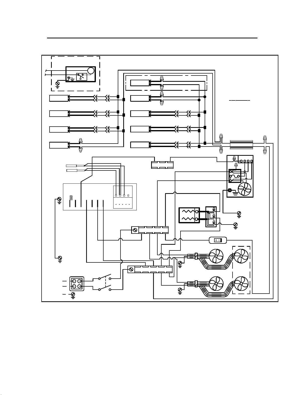
- 50 -
Self-Contained ECSS60SC Between 12/15/18 & 12/1/19
CONDENSATE PUMP
B(22)
R(23)
G(24)
CONDENSATE PUMP
STD ECSS
+B(R IB)
SHELF LAMP
SHELF LAMP
SHELF LAMP
TOP LAMP
- B
+B(R IB)
- B
+B(R IB)
- B
+B(R IB)
- B
DEFROST PROBE PB2
TEMP PROBE PB1
5 4 6 7
G(26)
IF OPTIONAL CONDO PUMP HOSE
HEATER IS USED, TIE HEATER
WIRES TO B22 & R23
P
B/R
B/R
B/BL
B/BL
B/R
B/R
B/BL
B/BL
B/R B/ R
B/BL
B/BL
B/R
B/BL
W
B
8 9 10 11
W
R(12)
B
TOP LAMP
TOP LAMP
SHELF LAMP
SHELF LAMP
SHELF LAMP
Y(6)
+B(RI B)
- B
+B(RI B)
- B
+B(RI B)
- B
+B(RI B)
- B
+B(RI B)
- B
TERM BLOCK
TERM BLOCK L2
B/R
B/BL
ECSS ONLY
CONDENSATE
PAN STD IMSS
R(23)
B/R
B/BL
B/R
B/BL
B/BL
B(22)
R(14)
B/BL
B/R
B/BL
B/R
B/R
B/BL
B/R
B/BL
B/RB/R
B/BL
Y(10)
B(17)
R(11)
B/R
B/BL
BL/R
R
BL
G(25)
2X4
BL
BR
G(24)
G
LIGHT SWITCH
COLOR CODE
B = BLACK
W = WHITE
G = GREEN
IF LIGHT WIRES
ARE B/BL & B
TIE B/BL TO RED
& B TO BLUE ON
POWER SUPPLY
POWER SUPPLY
1
BL = BLUE
Y = YELLOW
453
L2
L1
CONDENSING
UNIT
R(15)
R = RED
B
W
PRESS
CONTROL
B(5)
208-240V / 60Hz / 1PH
L2
R(2)
B(1)
L1
N
POWER SWITCH
B(13)
R(4)
B(3)
TERM BLOCK L1
RIB
RIB
EVAPORATOR FANS
IMSS
MODELS
ONLY
R(15)
B(16)
ECSS E3335
Page 51
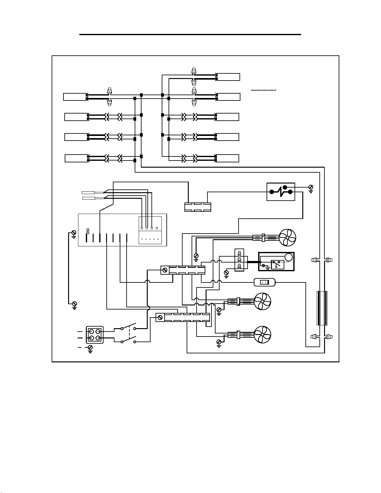
- 51 -
Remote ECSS40R Between 12/15/18 & 12/1/19
91-19629-2 12/27/18
ECSS40R ITC LED
+B(RI B)
+B(RI B)
- B
+B(RI B)
- B
+B(R IB)
- B
- B
B/R
B/BL
B/BL
B/BL
TOP LAMP
SHELF LAMP
SHELF LAMP
SHELF LAMP
DEFROST PROBE PB2
TEMP PROBE PB1
5 4 6 7
G(26)
B/R
B/BL B/BL
B/R
B/BL
B/R
B/R
B/BL
B/R B/R
B/R
B/BL
W
B
W
R(12)
B/R
B/BL
B/R
B/BL
B/R
B/BL
+B(RI B)
- B
+B(RI B)
- B
+B(RIB )
+B(RIB )
+B( RIB)
- B
- B
- B
TOP LAMP
TOP LAMP
SHELF LAMP
SHELF LAMP
SHELF LAMP
COLOR CODE
B = BLACK
W = WHITE
IF OPTIONAL CONDO PUMP HOSE
HEATER IS USED, TIE HEATER
WIRES TO B22 & R23
IF LIGHT WIRES
ARE B/BL & B
TIE B/BL TO RED
& B TO BLUE ON
POWER SUPPLY
B/R
B/BL
BL = BLUE
Y = YELLOW
G = GREEN
R = RED
B/R
B/BL
B/BL
B/R
B/BL
B/R
B/BL
B/BL
B/RB/R
Y(6)
Y(10)
B
TERM BLOCK
REFRIGERATION
R(11)
SOLENOID
G(25)
BASE FAN
2 X 4
B(22)
R(23)
G(24)
BR
BL
G
CONDENSATE PUMP
R(14) R(15)
LIGHT SWITCH
P
B
+ R
- BL
B(5)
208-240V / 60Hz / 1PH
L2
L1
R(2)
B(1)
N
B(13)
R(4)
B(3)
POWER SWITCH
TERM BLOCK L1
RIB
EVAPORATOR FANS
RIB
R(15)
B(16)
ECSS E3335
POWER SUPPLY
W
B B/BL
Page 52
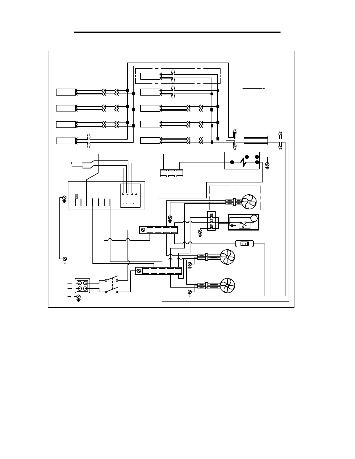
- 52 -
Remote ECSS60R Between 12/15/18 & 12/1/19
IF OPTIONAL CONDO PUMP HOSE
HEATER IS USED, TIE HEATER
WIRES TO B22 & R 23
+B(RIB )
SHELF LAMP
SHELF LAMP
SHELF LAMP
TOP LAMP
- B
+B(RIB )
- B
+B(RIB )
- B
+B(RIB )
- B
DEFROST PROBE PB2
TEMP PROBE PB1
5 4 6 7
G(26)
B(5)
B/BL
B/BL
B/R
B/BL
B/R
B/R
B/BL
B(13)
B/R
B/BL
B/RB /R
B/BL
B/R
B/BL
W
W
B
8 9 10 11
R(12)
91-19631-2 12/27/18 IMSS60R, IMSS84R & ECSS60R ITC LED
TOP LAMP
TOP LAMP
SHELF LAMP
SHELF LAMP
SHELF LAMP
+B(RIB)
+B(RIB)
+B(RIB)
+B(RIB)
+B(RIB)
B/R
B/BL
B/R
B/R
B/BL
B/BL
B/R B/R
B/BL
B/BL
B/BL
B/BL
B/R
B/R
B/BL
B/RB/R
B/BL
B/R
B/BL
COLOR CODE
B = BLACK
W = WHITE
G = GREEN
IF LIGHT WIRES
ARE B/BL & B
TIE B/BL TO RED
& B TO BLUE ON
POWER SUPPLY
R
POWER SUPPLY
BL = BLUE
Y = YELLOW
R = RED
- B
ECSS ONLY
- B
- B
- B
- B
BL
Y(6)
B
TERM BLOCK
Y(10)
REFRIGERATION
R(11)
JUMP R & Y
BL
SOLENOID
G(25)
G
B
BASE FAN OPTIONAL
RIB
TERM BLOCK L2
B(22)
R(23)
G(24)
2 X 4
BR
BL
G
CONDENSATE PUMP
P
R(15)R(14)
LIGHT
SWITCH
B
W
208-240V / 60Hz / 1PH
L2
L1
N
R(2)
B(1)
POWER SWITCH
R(4)
B(3)
TERM BLOCK L1
RIB
RIB
EVAPORATOR FANS
R(15)
B(16)
ECSS E3335
Page 53
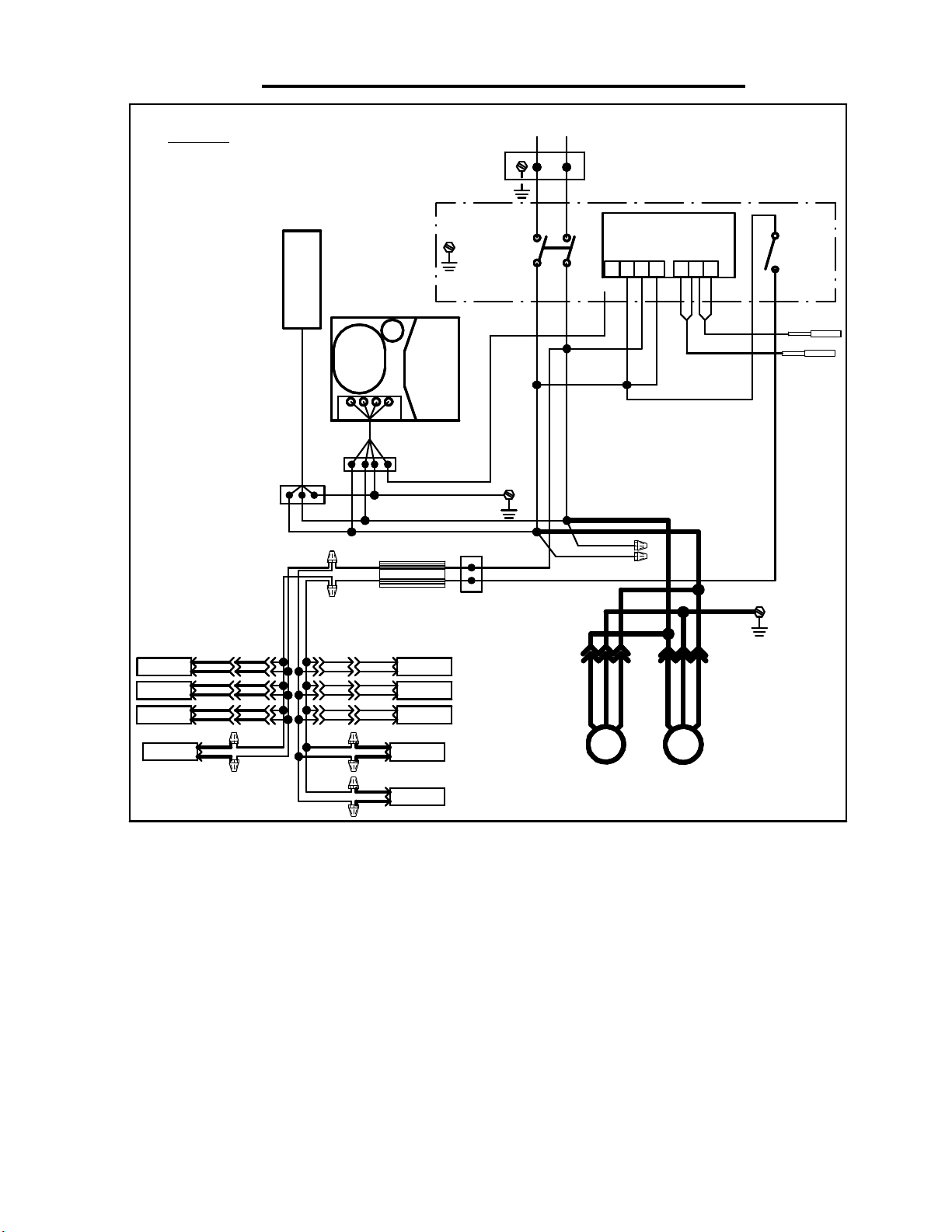
- 53 -
COLOR CODE
BLK = BLACK
W = WHITE
Self-Contained ECSS40SC After 12/1/19
L2
L1
N
CAREL
CONTROL
45
Y
R
BLK
BLK
BLK
R
BLK
B = BLUE
Y = YELLOW
CONDO
BRW= BROWN
G = GREEN
R = RED
PUMP
240V/3PH/60HZ
POWER
SWITCH
IN COMP.
FOR DETAILS.
SEE DIAGRAM
ECSS40
91-21214 1/17/20
LIGHT
96 7
10
8
BLK
W
W
BLK
SWITCH
DEFROST PROBE
PB2
TEMP PROBE
PB1
SHELF LAMP
SHELF LAMP
SHELF LAMP
TOP LAMP
+B(RI B)
- B
+B(RI B)
- B
+B(RI B)
- B
+B(RI B)
- B
R
B/BLK
B/R
B/R
B/BLK
B/R
B/BL
B/R
B/BL
B/R
B/BL
B/R
B/BLK B/BLK
B/R
B/R
B/BLK
G
B/R
B/BL
B/R
B/BL
B/R
B/BL
BLK
CONDENSING
R G
R
BLKBLK
BL-
POWER SUPPLY
R+
+B(RI B)
- B
+B(RI B)
- B
+B(RI B)
- B
+B(RI B)
- B
+B(RI B)
- B
UNIT
SHELF LAMP
SHELF LAMP
SHELF LAMP
TOP LAMP
TOP LAMP
BLK
G
R
W
B
BLK
R
BLK
R
BLK/RIB
BLK
BLK
BLK/RIB
EVAP.
M
DARK LINES REPRESENT
(3) CONDUCTOR CORD
BLK
BLK
M
IF LIGHT WIRES
ARE B/BL & B
TIE B/BL TO RED
& B TO BLUE ON
POWER SUPPLY
FANS
ECSS E3335
Page 54
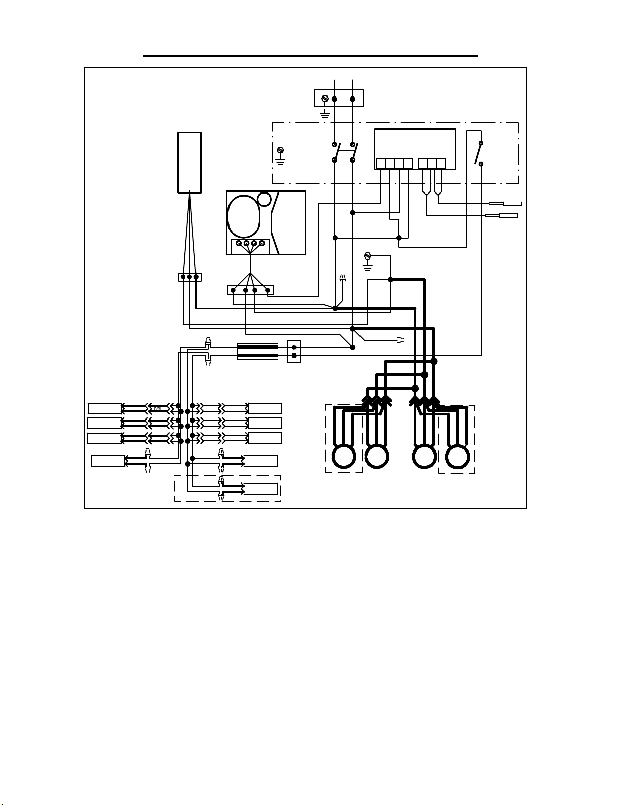
- 54 -
COLOR CODE
BLK = BLACK
W = WHITE
Self-Contained ECSS60SC AFTER 12/1/19
L2
L1
IMSS60 AND IMSS84
ECSS60
N
5 9
Y
BLK
R
91-21213 1/17/20
CAREL
CONTROL
4
6 7 10
8
BLK
W
R
BLK
W
BLK
BLK
B = BLUE
Y = YELLOW
CONDO PAN/
BRW= BROWN
G = GREEN
R = RED
PUMP
240V/3PH/60HZ
POWER
SWITCH
LIGHT
SWITCH
DEFROST PROBE
PB2
SHELF LAMP
SHELF LAMP
SHELF LAMP
TOP LAMP
+B(RI B)
- B
+B(RI B)
- B
+B(RI B)
- B
+B(RIB )
- B
BLK
G
R
B/BLK
B/R
B/R
B/BLK
B/R
B/BL
B/R
B/BL
B/R
B/BL
B/R
B/BLK B/BLK
B/R
B/R
B/BLK
B/R
B/BL
B/BL
B/R
B/BL
IN COMP.
FOR DETAILS.
SEE DIAGRAM
CONDENSING
BLK
R
BLK
BLK
G
TEMP PROBE
PB1
UNIT
R
POWER SUPPLY
+B(RIB )
- B
SHELF LAMP
+B(RIB )
- B
SHELF LAMP
+B(RIB )
- B
SHELF LAMP
- B
TOP LAMP
- B
TOP LAMP
G
R
W
B
BLK
ECSS60 ONLY
BLK
R
BLK
BLK
M
IMSS84 ONLY
BLK/R IB
BLK
BL-
R+
B/R
+B(RI B)
+B(RI B)
G
R
DARK LINES REPRESENT
(3) CONDUCTOR CORD
BLK/RIB
BLK
M
BLK
EVAP.
BLK
BLK
BLK
BLK/RIB
M
BLK
M
IF LIGHT WIRES
ARE B/BL & B
BLK/RIB
TIE B/BL TO RED
& B TO BLUE ON
POWER SUPPLY
FANS
IMSS84 ONLY
ECSS E3335
Page 55
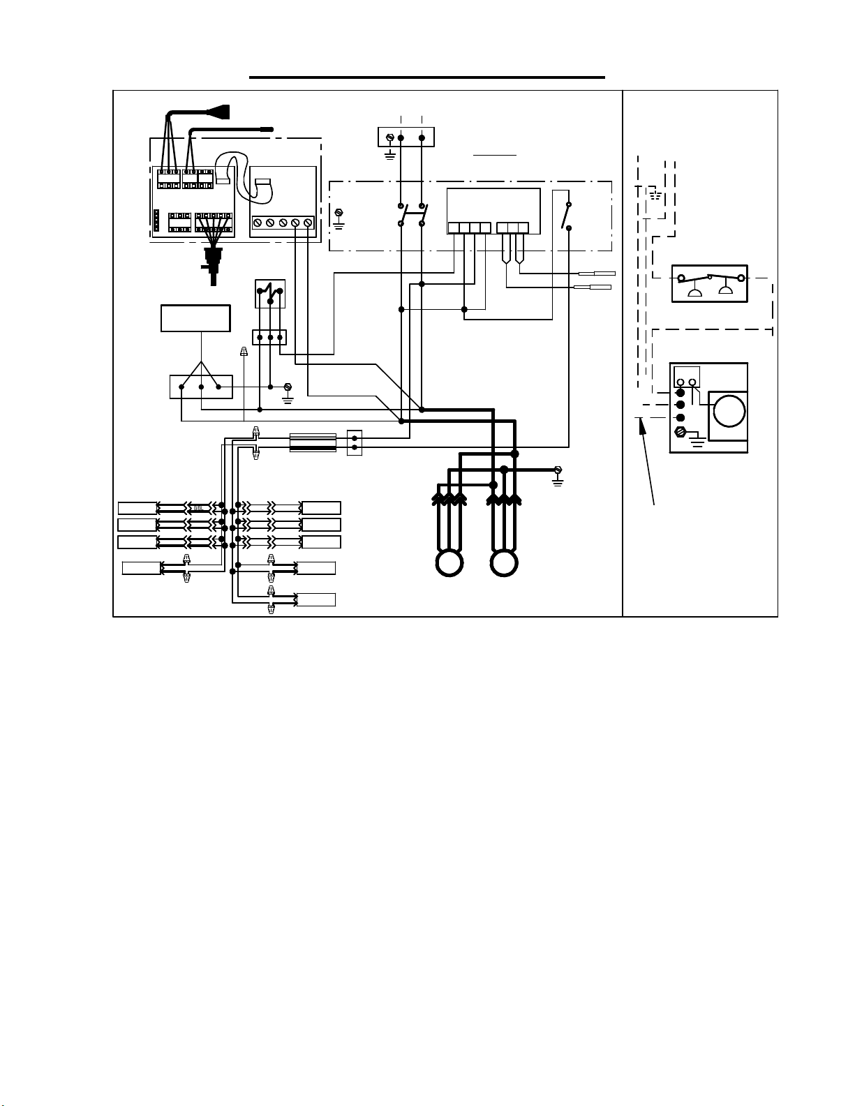
- 55 -
Remote ECSS40R After - 12/1/19
SHELF LAMP
SHELF LAMP
SHELF LAMP
TOP LAMP
PRESS. TRANS.
TEMP 1 TEMP 2Red
Blk Grn
TEMP 3
RSV-Blue
Empty
B A
Sh
CONDO
PUMP
BLK
+B(RIB )
- B
+B(RIB )
- B
+B(RIB )
- B
+B(RIB)
- B
Org
Yel
Red
Blk
Blk
Red
Grn
Wht
EEV
BLK
G
R
B/BLK
B/R
B/R
B/BLK
B/R
B/BL
B/R
B/BL
B/R
B/BL
B/R
B/BLK B/BLK
B/BLK
TEMP SENSOR
RIBBON
TEMP & VALVE
CABLE
CONTROL
345
REFRIG
SOLENOID
R G
G
R
BL-
R+
+B(RIB )
B/R
B/BL
+B(RIB )
B/R
B/BL
+B(RIB )
B/R
B/BL
B/R
+B(RIB )
B/R
+B(RIB )
2
1
BLK
POWER SUPPLY
- B
SHELF LAMP
- B
SHELF LAMP
- B
SHELF LAMP
- B
TOP LAMP
- B
TOP LAMP
240V/3PH/60HZ
N
POWER
SWITCH
R
BLK
R
W
B
BLK
BLK
L2
L1
91-21216 1/17/20
COLOR CODE
R
R
BLK = BLACK
W = WHITE
4
5 9
6 7 10
Y
R
BLK
CAREL
CONTROL
8
BLK
BLK
BLK
B = BLUE
Y = YELLOW
W
W
BLK
ECSS40R
BRW= BROWN
G = GREEN
R = RED
LIGHT
SWITCH
DEFROST PROBE
PB2
TEMP PROBE
PB1
BLK
SEPARATE
POWER SUPPLY
REMOTE
PRESSURE
CONTROL
HI/LO PRESS SW
Y
4 5
RELAY
Y
M
FAN
REMOTE
COMPRESSOR
BLK
BLK
BLK/RIB
M
DARK LINES REPRESENT
(3) CONDUCTOR CORD
IF LIGHT WIRES
ARE B/BL & B
TIE B/BL TO RED
& B TO BLUE ON
POWER SUPPLY
ALL FIELD WIRED
OPTIONAL REMOTE
MOUNTED & WIRED
COMPONENTS
BLK/R IB
BLK
BLK
EVAP.
M
FANS
ECSS E3335
Page 56
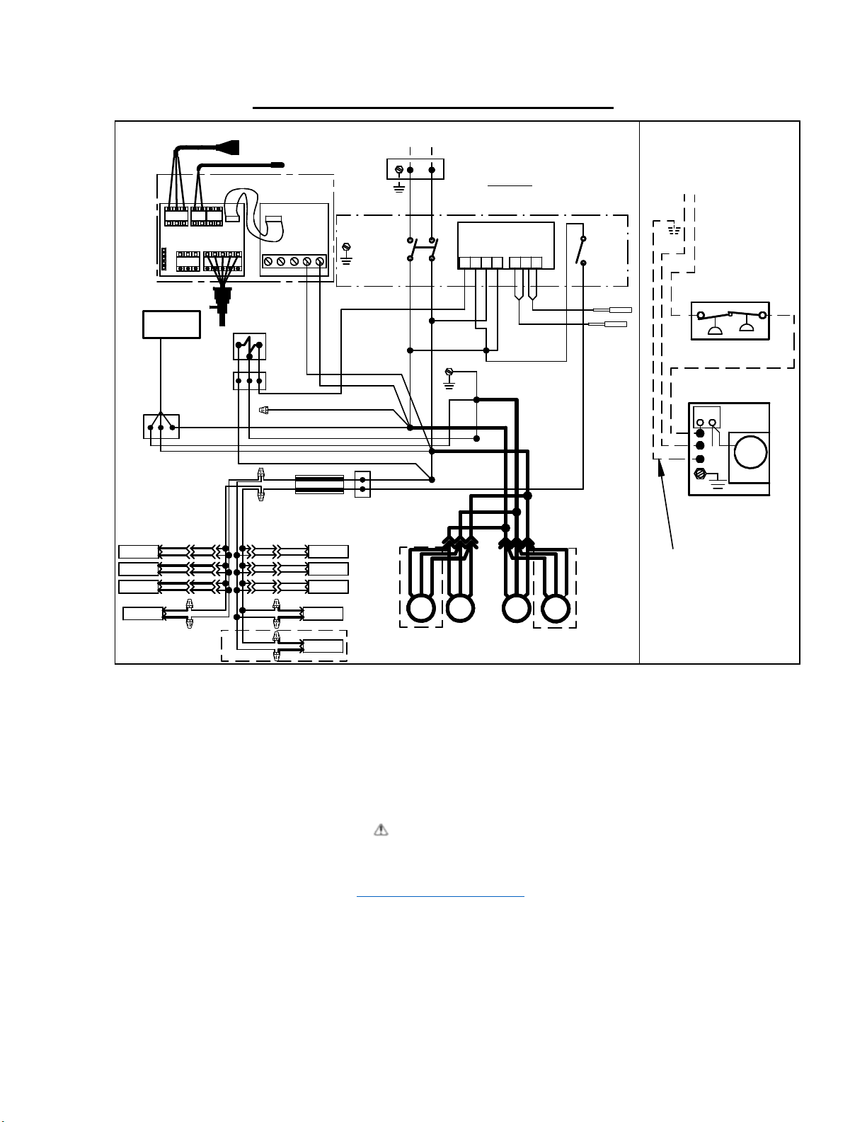
- 56 -
Remote ECSS60R After - 12/1/19
G
SHELF LAMP
SHELF LAMP
SHELF LAMP
TOP LAMP
PRESS. TRANS.
TEMP 1 T EMP 2Red
Blk Grn
TEMP 3
RSV-Blue
Empty
Sh B A
PUMP
BLK
R
+B(RIB)
B/R
- B
B/BL
+B(RIB)
B/R
- B
B/BL
+B(RIB)
B/R
- B
B/BL
+B(RIB)
- B
B/BLK B/BLK
L2
R
BLK
N
L1
BLK
BLK
BLK
BLK
M
IMSS84 ONLY
R
R
R
BLK/R IB
12
BLK
R
POWER SUPPLY
SHELF LAMP
SHELF LAMP
SHELF LAMP
TOP LAMP
TOP LAMP
240V/3PH/60HZ
POWER
SWITCH
BLK
W
B
ECSS MODELS ONLY
TEMP SENSOR
RIBBON
TEMP & VALVE
CABLE
CONTROL
Blk
Org
Yel
Red
Red
Grn
Wht
Blk
REFRIG
EEV
SOLENOID
R
B/BLK
B/R
B/R
B/BLK
B/R
B/BLK
345
G
BL-
R+
+B(RIB)
B/R
B/BL
- B
+B(RIB)
B/R
B/BL
- B
+B(RIB)
B/R
B/BL
- B
B/R
+B(RIB )
- B
B/R
+B(RIB )
- B
IMSS60R AND IMSS84R
ECSS60R
91-21215 1/17/20
COLOR CODE
BLK = BLACK
W = WHITE
CONTROL
45
Y
R
BLK
BLK
BLK
G
G
BLK/R IB
BLK
BLK
EVAP.
M
FANS
CAREL
BLK
BLK
B = BLUE
Y = YELLOW
96 7 10
8
BLK
W
W
BLK
DARK LINES REPRESENT
(3) CONDUCTOR CORD
BLK
BLK
BLK/RIB
M
IMSS84 ONLY
BLK
M
BRW= BROWN
G = GREEN
R = RED
LIGHT
SWITCH
DEFROST PROBE
PB2
IF LIGHT WIRES
ARE B/BL & B
BLK/RIB
TIE B/BL T O RED
& B TO BLUE ON
POWER SUPPLY
TEMP PROBE
PB1
SEPARATE
POWER SUPPLY
REMOTE
PRESSURE
CONTROL
HI/LO PRESS SW
Y
5
4
RELAY
REMOTE
COMPRESSO R
ALL FIELD WIRED
OPTIONAL REMOTE
MOUNTED & WIRED
COMPONENTS
Y
M
FAN
California Residents Only.
WARNING
This product can expose you to chemicals including chromium which is known to the State of
California to cause cancer and birth defects or other reproductive harm. For more information
go to www.P65Warnings.ca.gov
ECSS E3335
Page 57
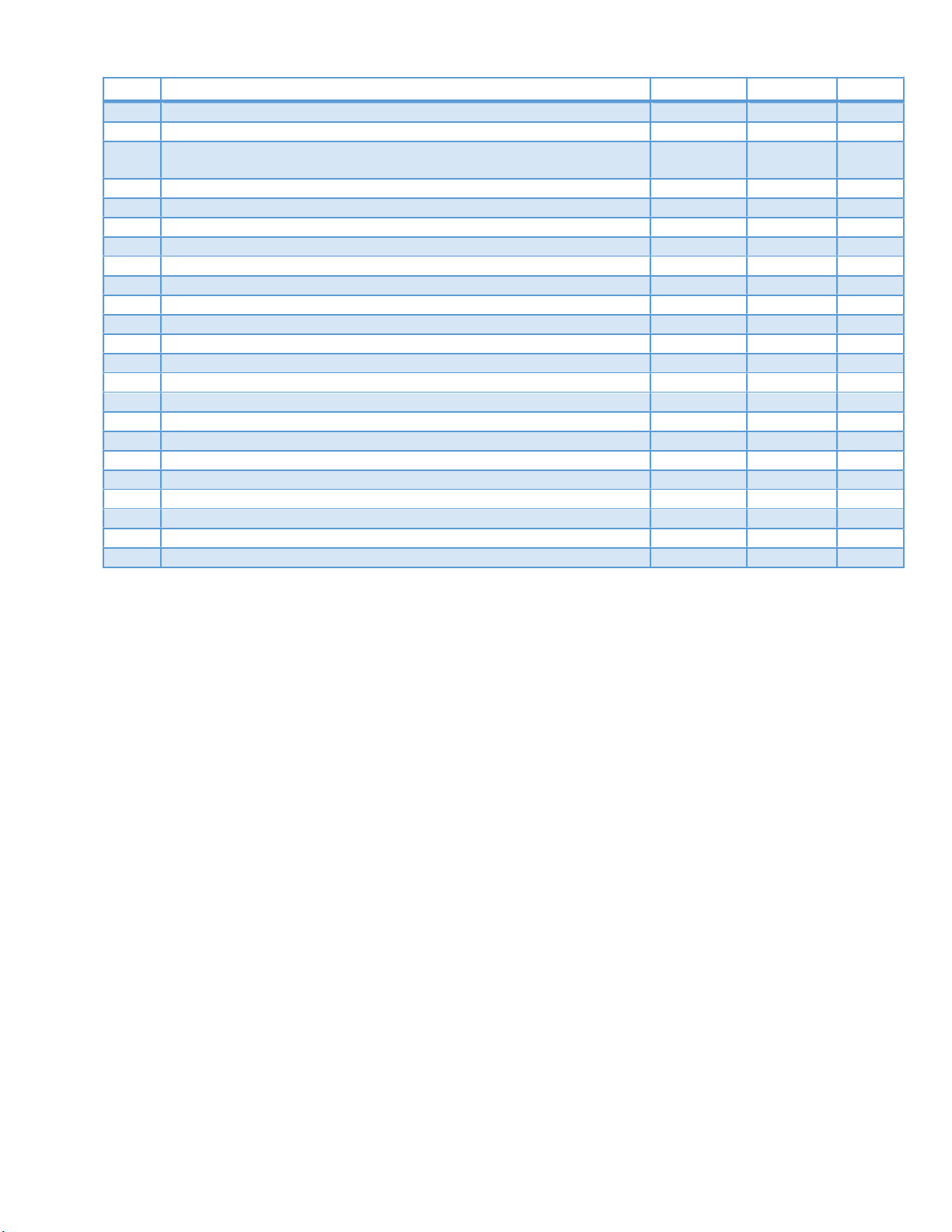
- 57 -
REV
CHANGE RECORD
APP’D
DATE
ECN#
G
H
J
K
LED LIGHT UPDATE SES 12/27/18
USER CONTROL, WARRANTY/SERVICE/PARTS UPDATE BJW 05/16/19
I ADDED DUAL PRESSURE CONTROL INFO, CORRECTED
SAFETY PRESSURE CONTROL ON PARTS LIST
ADDED NEW WIRE HARNESS AND EEV INFO KMC 9/17/19 3524
REVISED CONDO PAN SECTION SES 6/9/20 3625
ADC 8/6/19 3506
ECSS E3335
 Loading...