

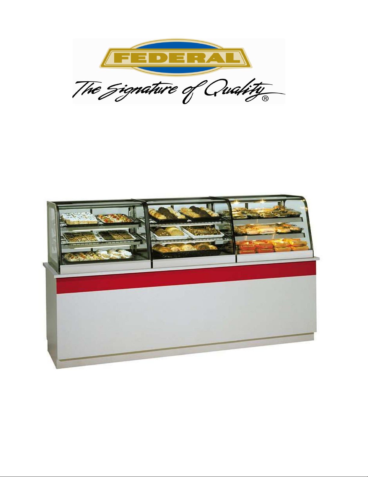
Federal CRR4828, CRB3628, CD3628, CRR3628, CRB4828 Installation & Operation Instructions
...Page 1
E2660
Revised 3/26/10
INSTALLATION & OPERATIONS INSTRUCTIONS
Self-Contained & Remote Refrigerated Models
& Non-Refrigerated Counter Displays
(Service & Self-Serve)
KEEP THIS MANUAL FOR FUTURE REFERENCE
Engineering and technical data are subject to change without notice.
FEDERAL INDUSTRIES 215 Federal Avenue Belleville, WI 53508
Toll Free 1(800) 356-4206 WI Phone (608) 424-3331 Fax: (608) 424-3234
- 1 -
Page 2
CONTENTS
INTRODUCTION.................................................................................................................................................................3
WARNING LABELS & SAFETY INSTRUCTIONS........................................................................................................4
PRE-INSTALLATION PROCEDURES.............................................................................................................................5
Inspection For Shipping Damage .......................................................................................................................5
GENERAL ELECTRICAL & GROUNDING ...................................................................................................................5
INSTALLATION INSTRUCTIONS ...................................................................................................................................5
Locating The Display Case.................................................................................................................................5
Removing Case From Shipping Skid & General Installation ......................................................................... 5-6
Cleaning..............................................................................................................................................................6
Dry CD Model Installation.......................................................................................................................................6
Cabinet Preparation ............................................................................................................................................6
Cord Options .................................................................................................................................................. 6-7
Refrigerated CRR Self Contained Model Installation..............................................................................................7
Cabinet Preparation ............................................................................................................................................7
Cord Options ......................................................................................................................................................8
Refrigerated CRB Self Contained Model Installation..............................................................................................8
Cabinet Preparation ........................................................................................................................................ 8-9
Cord Options ......................................................................................................................................................9
Refrigerated CRR Remote Model Installation .......................................................................................................10
Cabinet Preparation ..........................................................................................................................................10
Cord Options ....................................................................................................................................................10
Connect Remote Refrigeration Lines & Evaporator Condensate Drain ............................................................11
Refrigerated CRB Remote Model Installation .......................................................................................................11
Cabinet Preparation ..........................................................................................................................................11
Cord Options ....................................................................................................................................................12
Connect Refrigeration Lines..............................................................................................................................12
Refrigeration Installation (Refrigerated units)........................................................................................................13
Self Contained Models .....................................................................................................................................13
Remote Models.................................................................................................................................................13
Case Line Up Installation.......................................................................................................................................14
Top Joining Bracket..........................................................................................................................................14
Bottom Pedestal Joining ...................................................................................................................................15
END PANEL INSTALLATION ........................................................................................................................................16
SHELVING INSTALLATION & REMOVAL ................................................................................................................17
Shelf Brackets & Supports.......................................................................................................................... 17-18
Shelves and shelf light quantity........................................................................................................................18
Wire Shelf Installation......................................................................................................................................18
Glass Shelf Installation.....................................................................................................................................19
Metal Shelf Installation ....................................................................................................................................19
DOOR REMOVAL INSTRUCTION ................................................................................................................................20
OPERATING INSTRUCTIONS .......................................................................................................................................21
Controls ............................................................................................................................................................21
Shelves..............................................................................................................................................................21
Rear Package Shelf...........................................................................................................................................21
Placing Product Into Case.................................................................................................................................22
MAINTENANCE ................................................................................................................................................................23
Shelf Light Replacement ..................................................................................................................................23
Top Light Replacement (All Service and Dry Self-Serve) ...............................................................................23
Top Light Replacement (Refrigerated Self-Serve) ...........................................................................................23
PERIODIC MAINTENANCE ...........................................................................................................................................24
Cleaning Condenser Coil..................................................................................................................................24
CLEANING INSTRUCTIONS ..........................................................................................................................................24
Daily Cleaning............................................................................................................................................ 24-25
Weekly Cleaning ........................................................................................................................................ 25-26
SERVICE INFORMATION ..............................................................................................................................................27
Pre-Service Checklist ................................................................................................................................. 27-28
Special Service Situations.................................................................................................................................28
SALE & DISPOSAL...........................................................................................................................................................28
Owner Responsibility .......................................................................................................................................28
REFRIGERATION & ELECTRICAL DATA.................................................................................................................29
WIRING DIAGRAMS.................................................................................................................................................. 29-31
PARTS............................................................................................................................................................................32-33
- 2 -
Page 3
INTRODUCTION
Thank you for purchasing a Federal Industries display case. This manual contains important instructions for
installing and servicing the Curved Glass and Hi-Volume Refrigerated (including Dual Zone & Cold Deli)
and Non-Refrigerated Display Cases. A repair parts list and wiring diagram are also included in the manual.
Read all of these documents carefully before installing or servicing your case.
Read this manual before installing your case. Keep this manual and refer to it before doing any
service on the equipment. Failure to do so could result in personal injury or damage to the case.
NOTICE
NOTICE
Installation and service of the electrical components in the case must be performed by a licensed
electrician.
The portions of this manual covering components contain technical instructions intended only for persons
qualified to perform electrical work.
Improper or faulty hookup of electrical components in the case can result in severe injury or death.
All electrical wiring hookups must be done in accordance with all applicable local, regional, or
national standards.
DANGER
SERIAL NUMBER
Record the model and serial numbers of the case for easy reference. Always refer to both model and serial
numbers in your correspondence regarding the case.
Case Model__________________________ Serial Number______________________
Condensing Unit Model________________ Serial Number______________________
This manual cannot cover every installation, use, or service situation. If you need additional information,
call or write us:
WARRANTY/TECHNICAL SERVICE DEPARTMENT
Federal Industries
215 Federal Avenue
Belleville, WI 53508
Toll Free (800) 356-4206 / WI Phone (608) 424-3331
- 3 -
Page 4
WARNING LABELS & SAFETY
INSTRUCTIONS
This is the safety-alert symbol. When you see this symbol on your case or in the
manual, be alert to the potential for personal injury or damage to your equipment.
Be sure you understand all safety messages and always follow recommended precautions and safe
operating procedures.
NOTICE TO EMPLOYERS
You must make sure that everyone who installs, uses, or services your case is thoroughly
familiar with all safety information and procedures.
Important safety information is presented in this section and throughout the manual. The
Following signal words are used in the warning and safety messages:
DANGER: Severe injury or death will occur if you ignore the message.
WARNING: Severe injury or death can occur if you ignore the message.
CAUTION: Minor injury or damage to your case can occur if you ignore the message.
NOTICE: This is important installation, operation, or service information. If you ignore the
message, you may damage your case.
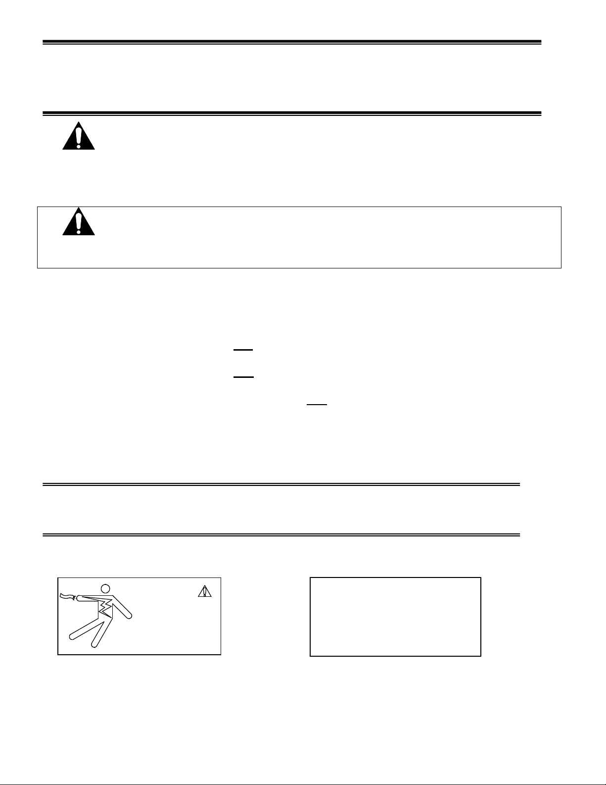
The warning and safety labels shown throughout this manual are placed on your Federal
Industries case at the factory. Follow all warning label instructions. If any warning or safety labels
become lost or damaged, call our customer service department at 1(800) 356-4206 for replacements.
CAUTION
RISK OF ELECTRIC
SHOCK DISCONNECT
POWER BEFORE
SERVICING UNIT.
91-12340
This label is located on the back of the display case. This label is located below the display pan.
CAUTION
HAZARDOUS MOVING PARTS
DO NOT OPERATE UNIT WITH
DISPLAY PANS REMOVED.
- 4 -
Page 5
PRE-INSTALLATION PROCEDURES
Inspection for Shipping Damage
You are responsible for filing all freight claims with the delivering truck line. Inspect all cartons
and crates for damage as soon as they arrive. If damage is noted to shipping crates, cartons, or if a
shortage is found, note this on the bill of lading (all copies) prior to signing.
If damage is discovered when the case is uncrated, immediately call the delivering truck line and
follow up the call with a written report indicating concealed damage to your shipment. Ask for an
immediate inspection of your concealed damage item. Crating material must be retained to show
the inspector from the truck line.
GENERAL ELECTRICAL & GROUNDING
DANGER:
display case can result in severe injury or death.
-All models are supplied with a power cord that is properly sized to the amperage requirements of the case.
See the electrical data plate located on the rear left interior of the case for the proper circuit size for each
case.
- The cord is factory installed protruding from the bottom rear corner of the case (see the “Cord Options”
section of this manual that pertains to your model case for alternate location.). If factory installed cord must
be relocated for desired application the electrical work must be performed by a licensed electrician.
-A separate circuit for each display case is recommended to prevent other appliances on the same circuit
from overloading the circuit and causing malfunction.
-All electrical wiring hookups must be done in accordance with all applicable local, regional, or national
electrical standards
Improper or faulty hookup of electrical components in the
INSTALLATION INSTRUCTIONS
General Display Case Location
The case should be located where it is not subjected to the direct rays of the sun, heating ducts, grills,
radiator, or ceiling fans, nor should it be located near open doors or main door entrances. Also, avoid
locations where there are excessive air movement or air disturbances. Allow at least 6” of clearance from
end of case to any walls or partitions.
Removing Case From Shipping Skid and General Installation
CAUTION:
door frames when removing the case from the skid or moving the case. Case
damage or glass breakage could result.
Do not push against the top glass, front glass, end glass, doors or
- 5 -
Page 6
1. Remove crate top and sides and note missing or damaged items as explained in the pre-installation
procedures outlined above.
2. Move the case as near as possible to the final location and before removing it from the shipping skid.
3. Remove the (4) brackets that secure the case to the shipping skid.
4. Prepare cabinet according to instructions in this section that pertain to your model.
5. Lift the case off of skid and into required position. Only lift the case from the frame channels located on
each end of the case
6. Fasten each case to cabinet with the (4) #12 screws supplied.
7. Rout electrical cord according to instructions in this section that pertain to your model.
C
ase must be sealed to the counter using a NSF listed sealant.
8. Install end panels.
Cleaning
For initial setup, clean the case as outlined in the “Weekly Cleaning” section of this manual.
Dry CD Model Installation
Cabinet Preparation
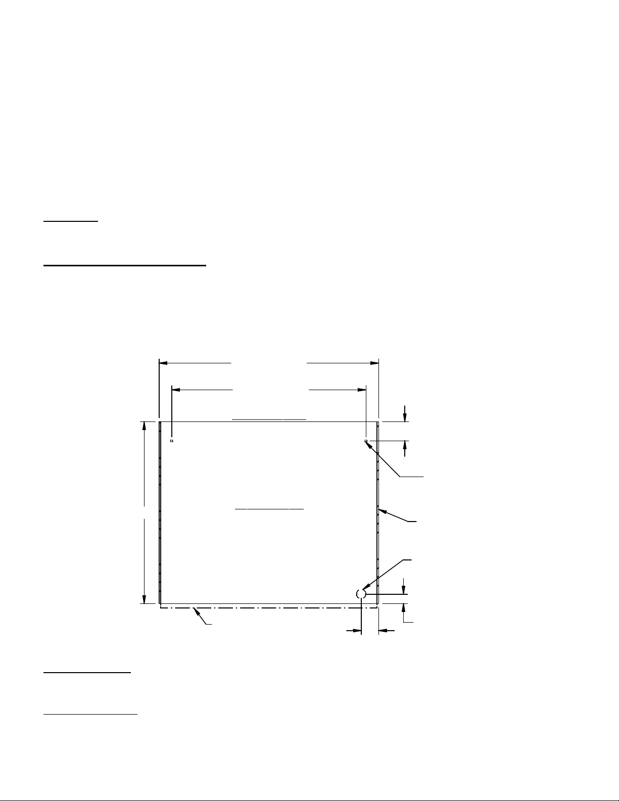
The CD models require (2) ½”dia. case fastening holes to be drilled through the counter top surface to
attach case to counter. Use the diagram below for hole placement location.
IMPORTANT: When placing cases in a line up the number of end panels used will be different. The cut
out and hole placement dimension will need to be adjusted for each particular line up circumstance. See
LINE UPS INTALLATION section of this manual.
35.0 (36" UNIT)
47.0 (48" UNIT)
31.0 (36" UNIT)
43.0 (48" UNIT)
CUSTOMER SIDE
FRONT
3.03
(2) 1/2" DIA
MTG. HOLES
29.0
CASE TOP VIEW
1/4" END
PANELS
1-1/2" HOLE
FOR CORD
STANDARD OPT.1
11/16 DOOR HANDLE
CLEARANCE
CORD OPTIONS
CORD OPTION1: The electrical cord is shipped from the factory protruding from the bottom rear corner of
the cases base. A 1-1/2”dia. hole must be drilled through the counter for the power cord clearance. See
diagram below for hole placement location.
CORD OPTION 2:An additional electrical cord connection hole is provided in the rear control panel next
to the case’s controls. A 1-1/2”dia hole through the counter is not required for this option. NOTE: Only a
licensed electrician must perform the electrical work required to move the cord to this optional position.
2.76
1.53
- 6 -
Page 7
DANGER:
Electric shock hazard. Do not operate unit with panels removed.
1. Remove the (8) screws holding the rear frame panel located under the door track and also remove
the 7/8” hole plug located next to the controls in the control panel.
2. Disconnect the power cord connections and move the cord and cord strain relief from the bottom
hole in the frame channel to the hole in the control panel and reconnect power cord. Plug bottom
hole in frame channel with the 7/8” hole plug removed from the control.
3. Reinstall the rear frame panel.
Refrigerated CRR Self Contained Models
Cabinet Preparation
The CRR Self Contained models have a large condenser compartment hanging from the rear of the unit that
contains the condenser/condensate evaporator unit. This compartment hangs off the rear edge of the
counter. The rear of the counter must be open to allow space for this compartment. The countertop top
should be flush with countertop back and the first top 8” of cabinet back must be flat with no doors.
IMPORTANT: The condenser air inlet and discharge louvers are located in the rear of the case. Do not
block these louvers and do not locate them near a source of heat. Clearance of 8” minimum must be
maintained for condenser air exchange.
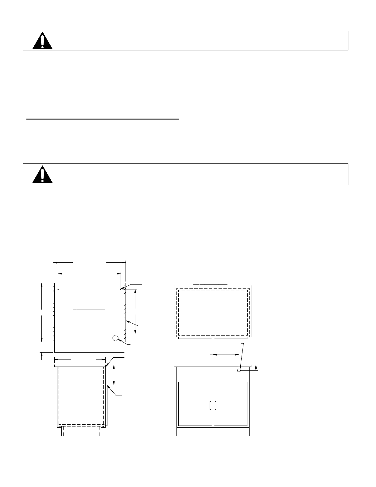
(2) ½”dia. case fastening holes will need to be drilled through the counter top surface to attach case to
counter with ¼” X 2” screws provided. Use the diagram below for hole placement location.
IMPORTANT: When placing cases in a line up the number of end panels used will be different. The cut
out and hole placement dimension will need to be adjusted for each particular line up circumstance. See
LINE UPS INTALLATION section of this manual.
DANGER:
Case must be fastened to counter and counter must be fastened to floor.
29.00
5.21 /
6.71 SS
36.0 (36"UNIT)
48.0 (48" UNIT)
31.0 (36"UNIT)
43.0 (43"UNIT)
FRONT
CASE TOP VIEW
EDG OF COUNTER TOP
CUTTING BOARD
25.25 MIN.
IMPORTANT:
UNIT MUST BE
FASTENED TO
COUNTER AND
CABINET MUST
BE FASTENED
TO FLOOR
(2) 1/2" DIA
MTG. HOLES
21.93
3/4" END
PANELS
CORD LOCATION
STANDARD OPT.1
COUNTER TOP MUST
BE FLUSH WITH REAR
OF CABINET.
10.0
DOORS ON REAR OF
CABINET MUST BE
10.0" FROM COUNTER
TOP SURFACE
TYPICAL CABINET CRB MODELS
FRONT
CUSTOMER SIDE
CORD LOCATION OPT.2
1-1/2" DIA HOLE
12.87 (36 UNIT)
18.87 (48 UNIT)
2.75
BACK
- 7 -
Page 8
CORD OPTIONS
CORD OPTION 1: The electrical cord is shipped from the factory protruding from the A 2-3/4” hole
located in the bottom rear corner of the condensing compartment and does not require a hole to be drilled
into the cabinet. (You may need to reach up into 2-3/4” hole to retrieve cord.)
CORD OPTION 2: The power cord can also be allowed to drop into counter interior space. This option
does not require any rewiring of the case, but does require a hole to be drilled into the back of cabinet.
1. Before placing the case onto the counter remove the (6) screws holding the condenser cover and remove
the condenser cover.
2. There is a 2-3/4” hole in the lower corner of the compartment and a 2-3/4”hole plug in the compartment
back. Remove the 2-3/4” plug from the back hole and place it into the bottom hole.
3. Install and fasten the case onto the counter.
4. Drill a 1-1/2” hole through the counter back in the location of the 2-3/4” hole for power cord to be
dropped into cabinet compartment.
5. Reinstall the condenser cover and the (6) screws.
OPTION 3: An electrical cord connection hole is provided in the rear control panel next to the controls. A
1-1/2”dia hole through the counter is not required for this option. NOTE: Only a licensed electrician must
perform the electrical work required to move the cord to this optional position.
1. Before or after the case has been installed onto the counter remove the (6) screws holding the condenser
cover and remove the condenser cover.
2. Remove the (4) screws holding the rear frame panel located under the door track. Loosen the (4) screws
holding the cutting board under each end of the cutting board. Tilt and lift the rear panel out from behind
the cutting board.
3. Remove the 7/8” hole plug located next to the controls in the control panel. Disconnect power cord
connections and move cord and cord strain relief from bottom hole in frame channel to the 7/8” hole in
the control panel. Reconnect power cord and plug bottom in frame channel with the 7/8” hole plug
removed from the control panel.
4. Reinstall the condenser cover and the rear frame panel and retighten the cutting board mounting screws.
DANGER:
Electric shock hazard. Do not operate unit with panels removed.
Refrigerated CRB Self Contained Models
Cabinet Preparation
The CRB Self Contained models have a large condenser compartment hanging from the bottom of case that
contains the condenser/condensate evaporator unit. This compartment hangs inside the cabinet
compartment. The interior of the cabinet must be open to allow space for this compartment and air
movement. The countertop must be cut to allow the case’s base and condenser compartment to drop into
the cabinet interior. Use the diagram below for cutout dimensions.
The condenser air inlet and discharge louvers are located on each side of the case condenser compartment.
The cabinet interior must have a divider that isolates intake and the exhaust sides of the condenser air. The
provided gasket must be attached to case in divider location to insure a seal between the air intake and air
discharge sides of condenser compartment. The Louvers provided must also be installed on each side of
these compartments for required condenser outside cabinet air exchange. The louvers can be installed in
either the front or the rear of the cabinet, as long there is a min. of 8”air space (drawing shows louvers in
rear for reference only). The cabinet compartment must not be used for storage or air restriction may occur.
(2) ½” dia. case fastening holes will need to be drilled through the counter top surface to attach case to
counter with ¼” X 2” screws provided. Use the diagram below for hole placement location.
IMPORTANT: Federal Industries reserves the right to deny warranty if the cabinet is not divided
internally and the cabinet louvers not installed properly, blocked or located near a source of heat.
- 8 -
Page 9
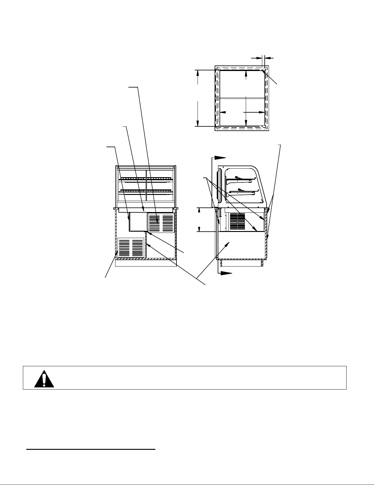
IMPORTANT: When placing cases in a line up the number of end panels used will be different. The cut
out and hole placement dimension will need to be adjusted for each particular line up circumstance. See
LINE UP INTALLATION section of this manual.
1.5
DISCHARGE GRILL
(PROVIDED)
LOCATED AS SHOWN
95 SQ. IN. MINIMUM
OF AIR OPENING
BASE OF UNIT MUST SIT INTO
OPENING AS SHOWN.
CONDENSER HOUSING,
DO NOT MOUNTGRILL BEHIND
CONDENSER HOUSING
33.5 (36)
32.8 (36)
44.8 (48)
45.5 (48)
26.9
TYPICAL COUNTER CUT OUT
GRILLS CAN BE INSTALLED ON EITHER FRONT
OR BACK OF CABINET. (FRONT SHOWN)
A
SEAL
WITH
GASKET
14.25 /
15.50 SS
GASKET
1/2" O HOLE
TO FASTEN CASE
TO COUNTER WITH
1/4" X 2" SCREWS
PROVIDED
SECTION AA
INTAKE GRILL(PROVIDED)
LOCATED AS SHOWN
95 SQ.IN. MINIMUM OF AIR OPENING
CORD OPTION 1: The electrical cord is shipped from the factory protruding from the bottom rear corner
of the base and will fall through the required cut in counter. After the case has been installed and fastened
onto the counter, plug cord into a proper power source.
CORD OPTION 2: An additional electrical cord connection hole is provided in the rear control panel
next to the case’s controls. A 1-1/2”dia hole through the counter is not required for this option. NOTE:
Only a licensed electrician must perform the electrical work required to move the cord to this optional
position.
DANGER:
1. Remove the (8) screws holding the rear frame panel located under the door track and also remove
the 7/8” hole plug located next to the controls in the control panel.
2. Disconnect the power cord connections and move the cord and cord strain relief from the bottom
hole in the frame channel to the hole in the control panel and reconnect power cord. Plug bottom
hole in frame channel with the 7/8” hole plug removed from the control.
3. Reinstall the rear frame panel.
Electric shock hazard. Do not operate unit with panels removed.
A
CENTER DIVIDER,
MUST BE SEALED
(GASKET PROVIDED)
Refrigerated CRR Remote Models:
- 9 -
Page 10
Cabinet Preparation
The CRR remote sets directly on top of the counter and refrigeration and evaporator condensate drain lines
must run through the counter top surface. The evaporator condensate drain must runs to a floor drain and
refrigeration lines to a remote condenser unit
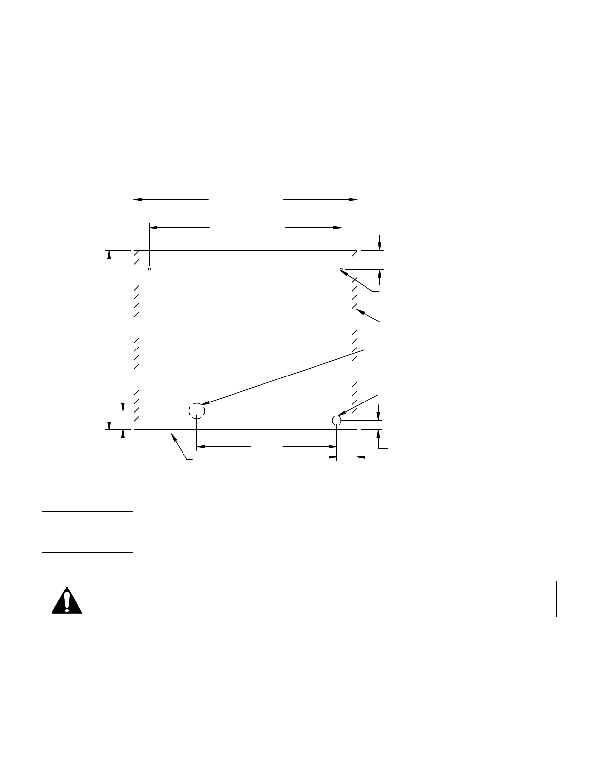
(2) ½”dia. case fastening holes will need to be drilled through the counter top surface to attach case to
counter with ¼” X 2” screws provided. A 2-1/2”dia. hole will also need to be drilled through counter top
for refrigeration lines and evaporator condensate tube connections. Use the diagram below for hole
placement location.
IMPORTANT: When placing cases in a line up the number of end panels used will be different. The cut
out and hole placement dimension will need to be adjusted for each particular line up circumstance. See
LINE UP INTALLATION section of this manual.
36.0 (36" UNIT)
47.0 (48" UNIT)
31.0 (36" UNIT)
43.0 (48" UNIT)
FRONT
3.03
CUSTOMER SIDE
(2) 1/2" DIA
MTG. HOLES
3/4" END
29.0
CASE TOP VIEW
PANELS
2-1/2" HOLE REFRIGERATION
AND EVAPORATOR
CONDENSATE DRAIN
1-1/2" HOLE
FOR CORD
3.0
22.62
11/16 DOOR HANDLE
3.26
STANDARD OPT.1
1.53
CLEARANCE
CORD OPTIONS
CORD OPTION 1: The electrical cord is shipped from the factory protruding from the bottom rear corner
of the cases base. A 1-1/2”dia. hole must be drilled through the counter for the power cord clearance. See
diagram below for hole placement location.
CORD OPTION 2: An additional electrical cord connection hole is provided in the rear control panel next
to the case’s controls. A 1-1/2”dia hole through the counter is not required for this option. NOTE: Only a
licensed electrician must perform the electrical work required to move the cord to this optional position.
1. Remove the (8) screws holding the rear frame panel located under the door track and also remove
the 7/8” hole plug located next to the controls in the control panel.
2. Disconnect the power cord connections and move the cord and cord strain relief from the bottom
hole in the frame channel to the hole in the control panel and reconnect power cord. Plug bottom
hole in frame channel with the 7/8” hole plug removed from the control.
3. Reinstall the rear frame panel.
DANGER:
Electric shock hazard. Do not operate unit with panels removed.
- 10 -
Page 11

Connect remote refrigeration lines and condensate evaporator drain.
1. Remove the rear refrigeration line cover by removing the (4) screws on each end of base and the
(3) screws from under the rear frame channel.
2. Connect remote refrigeration lines through the 2-1/2” hole in counter as described in the Remote
Connection section in this manual.
3. Connect the provided condensate evaporator drain hose through the 2-1/2” hole in counter by
pushing it onto the drain fitting and secure it with provided hose clamp. Run the hose to a floor drain
or a remote condensate evaporator pan.
Refrigerated CRB Remote Models:
Cabinet Preparation
The CRB Remote models have a large condensate evaporator compartment hanging from the bottom of
case that contains the condensate evaporator pan. This compartment hangs inside the cabinet compartment.
The interior of the cabinet must be open to allow space for this compartment. The countertop must be cut to
allow the case’s base and condenser compartment to drop into the cabinet interior. Use the diagram below
for cutout dimensions.
IMPORTANT: When placing cases in a line up the number of end panels used will be different. The cut
out and hole placement dimension will need to be adjusted for each particular line up circumstance. See
LINE UP INTALLATION section of this manual.
The condensate air louvers are located on each side of the condensate evaporator compartment. Do not
block these louvers. The louver panel provided with case must be installed in the cabinet to allow
condensate moisture to vent. The louver can be placed on any side of cabinet, but must be as near to the top
as possible. A 6” minimum clearance must be maintained from cabinet louver.
Also (2) ½”dia. case fastening holes will need to be drilled through the counter top surface to attach case to
counter with ¼” X 2” screws provided. Use the diagram below for hole placement location.
IMPORTANT: When placing cases in a line up the number of end panels used will be different. The cut
out and hole placement dimension will need to be adjusted for each particular line up circumstance. See
LINE UP INTALLATION section of this manual
1.1
29.0
CORD OPTION
26.9
36.0 (36 UNIT)
48.0 (48 UNIT)
33.5 (36 UNIT)
45.5 (48 UNIT)
FRONT
CASE TOP VIEW
CORD LOCATION
STANDARD OPT.1
3.03
(2) 1/2" DIA
MTG. HOLES
TOP CUT
OUT
3/4" END
PANELS
11/16 DOOR HANDLE
CLEARANCE
- 11 -
Page 12

OPTION 1: The electrical cord is shipped from the factory protruding from the bottom rear corner of the
base and will fall through the required cut in counter. After the case has been installed and fastened onto
the counter, plug cord into a proper power source.
CORD OPTION 2: An additional electrical cord connection hole is provided in the rear control panel next
to the case’s controls. A 1-1/2”dia hole through the counter is not required for this option. NOTE: Only a
licensed electrician must perform the electrical work required to move the cord to this optional position.
1. Remove the (8) screws holding the rear frame panel located under the door track and also remove
the 7/8” hole plug located next to the controls in the control panel.
2. Disconnect the power cord connections and move the cord and cord strain relief from the bottom
hole in the frame channel to the hole in the control panel and reconnect power cord. Plug bottom
hole in frame channel with the 7/8” hole plug removed from the control.
3. Reinstall the rear frame panel.
Connect remote refrigeration lines
1. Remove the cover by removing the (4) screws on the bottom of case inside the cabinet
compartment.
2. Connect remote refrigeration as described in the Remote Connection section in this manual. A 2-3/4
hole through the condensate evaporator compartment is provided.
3. Make sure that the drain line has not been dislodged during shipment and that the drain trap is
located properly over the water reservoir of the condensate evaporator pan.
4. Reinstall evaporator condensate cover.
DANGER:
Electric shock hazard. Do not operate unit with panels removed.
.
Condensing Unit Air Flow.
The remote condensing unit must be installed to allow separation of coil intake air and coil discharge
air. The coil discharge air must not be allowed to recirculate back into the coil intake. Condensing unit
coil intake air temperature should be as cool as possible and should not exceed 80 Degrees F.
- 12 -
Page 13

Refrigeration Installation
(Refrigerated units)
Self Contained Models
The self-contained models are shipped from the factory with a completely operational 134A refrigeration
system and require no modifications or adjustments upon installation.
Remote Models
The remote models are designed to use 134A refrigerant and shipped from the factory with the evaporator
coil, expansion valve, refrigerant solenoid valve and thermostat. The thermostat senses interior case
temperatures and opens and closes the refrigerant solenoid valve as needed to maintain proper case
temperatures. The condensing unit is optionally supplied from the factory for remote location installation.
REMOTE DISPLAY CASE
EXPANSION
EVAPORATOR COIL
VALVE
INSTALL
LOW PRESSURE
REMOTE
CONDENSING
UNIT
CUTOUT
LIQUID LINE
SOLENOID
VALVE
SUCTION LINE (INSULATED)
THERMOSTAT
LIQUID LINE
INSTALL
FILTER DRIER
1. Mount condensing unit indoors as close to the remote display case as practical. The refrigeration line
should be as short as possible and must not exceed 30 feet.
2. All refrigeration and/or electrical materials between the condensing unit and display case are to be
supplied by installing contractor.
3. Route properly sized and designed refrigeration lines from the condensing unit to the cabinet.
Horizontal suction lines should be pitched downward towards the condensing unit at least ½” per 10’
run to aid the oil drainage. A “P” trap must be installed in the suction line at the foot of every riser to
insure oil return. Dry nitrogen should be used to flow through tubing while brazing refrigeration lines.
4. Suction line must be insulated the entire length with Armaflex (or equivalent). Do not run liquid line
inside insulation with suction line.
5. The filter drier, sightglass, and low-pressure control are not furnished with remote display case models.
The recommended low pressure setting for R134a refrigerant is 32# cut in and 0# cutout.
6. Leak check condensing unit, cabinet, and all connecting tubing. Cabinet and condensing unit tubing
should be checked to insure no leaks occurred during shipping or from rough handling.
Make certain all refrigeration valves are opened and evacuate system to 500 microns. Charge the
system with refrigerant type specified on the data plates.
- 13 -
Page 14

Case Line Up Installation
Follow the “Case Installation” procedures in this manual for each display case that is going to be adjoined
in a lined up. Additional cases must be place directly next to the adjoining end of the first case
IMPORTANT: BEFORE CUTTING COUNTER TOP:
When placing cases in a line up the number of end panels used will be different. The cut out and hole
placement dimension will need to be adjusted for each particular line up circumstance as listed below.
-REFRIGERATED TO REFRIGERATED: (1) 3/4" end panel attached to one of the cases. It does not
matter which case.
- REFRIGERATED TO DRY: (1) 3/4" end panel attached to the refrigerated case.
- REFRIGERATED TO HOT: (1) 1-1/2" end panel attached to the refrigerated case.
- DRY TO HOT: (1) 1-1/2" end panel attached to the refrigerated case.
Note: The end panel screws and plastic spacers are not used on the case that does not get an end panel
when being butted up to a case with an end panel. Remove them from case and discard.
Once the cases are placed together with proper end panel(s). They will need to be pushed together as close
as possible keeping the front of the cases in alignment. Once adjoining case is in proper position complete
all of the procedures outlined in the “Case Installation” section in this manual before installing the joining
kit as outlined below.
Top Joining Bracket
TOP REAR JOINING BRACKET
(2) #6 X 3/8 BLACK SCREW
BLACK PLASTIC PLUG
LOCATION
All cases joined together should have a top joining bracket installed to keep the top of the case tight
together. There are different brackets included with each case to cover most joining combination needs. If
no holes are provided, drill a 1/8”dia x ½” deep hole in location needed for bracket attachment.
1. Remove the black plug from the hole located on the upper rear corner of case.
2. Find the correct bracket shipped with case and place it over the end panel(s).
3. Hold the two cases together as much as possible to eliminate gap and fasten with screw.
- 14 -
Page 15

Bottom Pedestal Joining
FRONT
PEDESTAL JOINING PLATE
REAR
The CRR model cases and cases with optional pedestal have a 2-3/4” pedestal that sets on top the counter.
When these cases are joined there is a gap between the pedestals. Two joining plates are provided for these
models.
The front plate is attached with self adhesive tape as follows:
1. Clean the front corner area on pedestal with rubbing alcohol
2. Remove adhesive backing strips from pedestal joining plate.
3. Center plate over opening and press firmly into place.
The rear plate must be attached with provided screws as follows: (Screw removal will be required to access
condenser compartment so do not use adhesive backing.)
1. Center plate at top of condenser compartments directly below cutting boards.
2. Mark location of (2) screw holes in cover plate on to each condenser panel.
3. Attach cover plate with (2) self drilling screws.
- 15 -
Page 16

END PANEL NSTALLATION INSTRUCTIONS
END GLASS
3/4" ON REFRIGERATED UNITS
1/4" ON DRY UNITS
1-1/2" BETWEEN HOT & DRY OR HOT & REFRIG
PLASTIC SPACER
10-32 SCREW
End panels are Ordinarily shipped loose from the factory and need to be installed once the case fastened to
the counter. When placing cases in a line up the number of end panels and end panel type will be different
for each line up circumstance. See Case Line Up Installation section of this manual.
1. Place end panel on to the side of case and align holes.
2. Place a plastic spacer on to a screw and install the screw through the hole on end panel and into the
case. Do not tighten screws until all (3) screws are started and then snug screws up, but do not over
tighten or glass breakage may occur.
3. Repeat for all ends that require an end panel.
- 16 -
Page 17

SHELVING INSTALLATION & REMOVAL
Shelf Brackets and Supports
SHELF LIGHT,
SET INTO FRONT NOTCH
ON SHELF BRACKET
REAR SHELF SUPPORT,
SET INTO REAR NOTCH
ON SHELF BRACKETS
CLEAR BUMPER, ATTACH
TO FRONT OUTSIDE CORNER
OF ALL BRACKETS
SHELF LIGHT CORD CLIP & SCREW,
SCREW TO SHELF BRACKET
ON SIDE OF SHELF LIGHT CORD
2 POSITION SHELF BRACKET,
HOOK INTO SHELF STANDARD
1. Turn the light switch to the off position. Remove rear doors as described in the “Rear Door Removal”
section of this manual to allow access to interior of case.
2. For first time installation it may be necessary to attach the clear plastic clips to only the shelf brackets
located on the side of the shelf light cord. Use the 6-32 x ¼ flat head screws supplied with unit to
attach clear plastic clips to the 1/8 hole on the inside of the shelf brackets. It may also be necessary to
attach the clear bumper to the outside end towards the side glass of each shelf bracket. The bumper
prevents damage to the end glass. These steps may have already been performed at the factory for you.
Insert a longer bottom shelf bracket in the desired shelf standard slot on one side of case (bumper side
towards end glass). Follow the instruction in the illustration below. Place the additional longer bottom
shelf bracket in the same shelf standard slot on the opposite end of case. Repeat for shorter top shelf
tier.
INSTALLATION
SHELF STANDARD
TOP HOOK
1
2
3
BOTTOM TAB
4
6v NOTCH
0v NOTCH
1. Place shelf bracket top hook into desired shelf
standard slot.
2. Lift shelf bracket top hook to allow shelf bracket
bottom tab to clear shelf standard slot.
3. Swing shelf bracketbottom tab into shelf standard
slot.
4. Place the desired shelf bracket notch of 0, 6, or 12
degrees onto bottom of shelf standard slot.
SHELF BRACKET
3
1. Lift shelf bracket up to allow shelf bracket notch
to clear the bottom of shelf standard slot.
2. Swing shelf bracket bottom tab out of shelf
standard slot.
3. Drop shelf bracket down to allow shelf bracket top
hook to clear top of shelf standard slot.
4. remove shelf bracket top from shelf standard slot.
1
REMOVAL
2
4
CLEAR BUMPER
TOWARDS END PANEL
- 17 -
Page 18

3. Hang one end of shelf light housing on the front notch of a shelf bracket and then the other end of shelf
light housing on the notch of the shelf bracket on the opposite end. Repeat for each additional shelf
tiers. NOTE: On models without shelf lights, use a shelf support instead of a shelf light housing.
4. Push shelf light cords into clear plastic clip located on inside of shelf brackets.
5. Remove the cap from the appropriate female light sockets. If socket is not being used for a shelf light,
the cap must be plugged into socket for entire light system to operate. NOTE: Grip each side of cap
firmly and wiggle and pull cap straight out of socket. Do not roll cap during removal.
6. Plug in each shelf light by aligning the male pins on the appropriate shelf light cord plugs with the
female light sockets and push together. NOTE: Do not roll plug during insertion.
7. Hang one end of the shelf support on to the rear notch of one shelf bracket and then on the rear notch of
the shelf bracket on the opposite side. Repeat for additional shelf tiers.
8. Place supplied shelving onto shelf supports as outlined in the appropriate “Shelf Installation” section of
this manual.
9. On units with sliding rear doors, re-install both rear doors by lifting top of door into top track and
swinging bottom of door onto bottom track. Install door labeled “inner door” first on inner track and
door labeled “outer door” second on outer track.
Shelves and shelf light quantity
It is not required that all shelves and shelf lights supplied with each case are used. The quantity of shelves
and shelf lights can be tailored to your specific needs. If the supplied quantity of shelves and shelf lights
are not required, cap unused female socket located in interior of the case mullion with caps supplied.
Failure to do so will prevent entire lighting system from operating.
Wire Shelves Installation
WIRE SHELF,
PUSH INTO CLIPS ON
REAR SHELF SUPPORT
WIRE SHELF RETAINER CLIP & SCREW,
SCEW TO EACH END OF SHELF
SUPPORT ON BOTH SUPPORTS
(WIRE SHELF MODELS ONLY)
WIRE SHELF
PUSH REAR WIRE
INTO WIRE SHELF
CLIP
1. For first time installation, it may be necessary to attach the clear plastic clips to each end of the rear
shelf supports. Use the 6-32 x ¼ flat head screws supplied with unit to attach clear plastic clips to the
1/8 hole on each side of shelf support. This step may have already been performed at the factory for
you. Repeat for each rear shelf support tier. (See illustration E1594-2 Detail C) NOTE: On 73” long
shelf supports, attach (2) additional clear plastic clips into 1/8 holes near the center of rear shelf
supports.
2. With rear sliding doors removed, place front of wire shelf onto front shelf light. (On front shelf support
for models without shelf lights)
3. Snap the rear of shelf into the clear plastic clips on rear shelf support.
4. Repeat 2 & 3 for each tier.
- 18 -
Page 19

Glass Shelves Installation
GLASS SHELF RETAINER
GLASS SHELF, AFTER RETAINERS
ARE ATTACHED RETAINER
STRADDELS REAR SHELF SUPPORT
(GLASS SHELF OPTION ONLY)
GLASS SHELF RETAINER,
CLEAN GLASS WITH RUBBING
ALCHOL & ATTACH RETAINER
O BOTTOM CORNER OF GLASS.
(GLASS SHELF OPTION ONLY)
TO BE LOCATED, IN FAR
CORNER OF GLASS SHELF
FLUSH WITH EDGES
GLASS SHELF CLEAR BUMPER
ATTACH TO SHELF LIGHT
FOR FRONT OF GLASS TO SET ON.
(GLASS SHELF OPTION ONLY)
1. For first time installation attach (2) glass shelf holders to each glass shelf. Remove backing from tape
located on flat side of glass shelf holder. Position the glass shelf holders in the (2) far corners of glass.
Repeat for each glass shelf. Attach a clear bumper on both sides of the light housing top surface for the
front of the glass to set on. This step may have already been performed at the factory for you.
NOTE: Clean area of glass where glass shelf holder is to be located with rubbing alcohol and let air
dry before installing shelf glass holder.
2. With rear sliding doors removed, place front of glass shelf onto front shelf light. (On front shelf
support for models without shelf lights.)
3. Let the rear of the glass shelf onto the rear shelf support so that the glass shelf holder straddles the rear
shelf support. If clear plastic clips were factory-installed on top of rear shelf support, remove and
discard clear plastic clips.
4. Repeat steps 2 & 3 for each tier.
Metal Selves Installation
METAL SHELF
METAL SHELF
ALIGN SLOT IN SHELF
WITH TAB ON FRONT
OF SHELF BRACKET.
1. With rear sliding doors removed, place front of the metal shelf onto front shelf light. (On front shelf
support for models without shelf lights)
2. Align slots on each side of the shelf with the tabs on the front of each shelf bracket.
- 19 -
Page 20

DOOR REMOVAL INSTRUCTIONS
ALL SERVICE CASES & SELF SERVE DRY
UPPER TRACK
LOWER TRACK
1. LIFT UP
2. SWING BOTTOM OUT
1. Start with the outer door and lift the door upward until the bottom edge of door clears the
lower track and then swing the bottom of the door outward and down out of upper track.
2. After the outer door is removed repeat the procedure for the inner door.
3.
Reverse this procedure for door reinstallation. The doors are not interchangeable.
SELF SERVE REFRIGERATED CASES
INNER DOOR
CATCH SLOT
INNER DOOR
CATCH
UPPER TRACK
2. SWING BOTTOM OUT
1. LIFT UP
2. SWING BOTTOM OUT
1. LIFT UP
INNER LOWER TRACK
LOWER TRACK
1. Start with the outer outside door and lift the door upward until the bottom edge of door
clears the lower track and then swing the bottom of the door outward and down out of
upper track.
2. Remove the outer inside door using the same procedure.
3. The inner door set can then be removed using the same procedure starting with the inner
outside door followed by the inner inside door.
4.
Reverse this procedure for door reinstallation starting with the inner inside door
followed by the inner outside door. Check that the doors slide freely.
5.
Replace the outside inner door and the outside outer door. Be sure to slide the inner door
catch into the inner door catch slot for each door.
Note: None of the doors are not interchangeable and they must be replaced in the same
location that they where removed from.
- 20 -
Page 21

OPERATING INSTRUCTIONS
Controls (Refrigerated Units)
Light Switch
This switch controls the power to the lighting circuit. The switch rocker is red in the “on” position,
black in the “off” position.
Temperature Control
This controls the refrigerated side by cycling the compressor/condensing unit. It has an “off”
position and the coldest setting when the knob is set all the way in the clockwise position. Set this
control at the lowest setting possible, while maintaining desired case temperature.
Controls (Non-Refrigerated Units)
Power Switch
This switch controls the power to the lighting circuit and to the optional interior fan if supplied.
The switch rocker is red in the “on” position and black in the “off” position.
Shelves
Each display is furnished with shelves that are adjustable up and down and can be tilted in two
angular positions. See “Shelving Installation & Removal” section of this manual for proper
installation, adjustment and removal of shelving.
Rear Package Shelf Pedestal
The rear package shelf is provided with the 2-3/4” pedestal option. It is not adjustable up and down.
And can be removed by loosening the retainer screws under the shelf and sliding out through
keyhole slots. After completing shelving installation as outlined in “Shelving Installation and
Removal” section of this manual you may begin placing product into the display case.
(optional)
- 21 -
Page 22

Placing Product into Case
- Do not exceed 100 pounds of weight per shelf. Heavy product should be distributed evenly across
the entire shelving area.
- Determine desired shelving location and angle before placing product in case. Product must be
removed to readjust shelf location and angle.
(Refrigerated Models)
- Do not overhang the front of wire shelves with product. Product may overhang rear of shelf, but
allow a minimum of 1-1/2” between product and rear door. Improper clearance in front and rear of
shelf will block the refrigerated airflow and could cause product loss.
-Do not block the slots along the front or rear of the case display pan. Covering these slots will
block the refrigerated airflow and could cause product loss.
-The display pan is removable for cleaning and can become dislodged in shipment. To ensure
proper airflow and performance of the case, make sure that the display pan is pushed completely
down into evaporation tub. Check that the pan is installed properly before placing product the
display pans.
-Allow refrigerated models to run for at least two hours before placing pre-chilled product into unit.
Turn temperature control to the lowest possible position that maintains required interior cabinet
temperature.
-CASE SHOULD BE STOCKED WITH PRE-CHILLED PRODUCT
ONLY.
ATTENTION:
- Federal refrigerated display cases are designed to operate in a
maximum environment of 75 DEG. F and 55% relative humidity.
Exceeding these limits could cause poor case performance and
sweating of glass panels.
- 22 -
Page 23

MAINTENANCE
Shelf Light Bulb Replacement
1. Remove both rear doors as described in the “Door Removal” section of this manual.
2. Remove shelving from unit through rear door opening as described in the “Shelving Installation and
Removal” section of this manual.
3. Unplug appropriate light housing cord from socket and remove light fixture from unit through rear door
opening.
4. Remove the plastic lens. Starting at one end of the light, push in on the topside of plastic lens until the
plastic lens clears the light fixture housing and peel the lens away from the fixture housing edge.
5. The shelf light fixture uses a spring-loaded socket at one end. To remove the bulb push the bulb
towards the spring-loaded socket until the opposite ends drops out of the socket.
6. Reinstall new bulb in the same manner as described in the Bulb Removal Procedure. Be sure bulb is
secure in bulb receptacles.
Note: Be sure to use a direct equivalent to the original bulb.
Top Light Bulb Replacement (All Service cases and Dry Self Serve Cases)
1. Remove both rear doors as described in the “Door Removal” section of this manual.
2. Remove shelving from unit through rear door opening as described in the “Shelving Installation and
Removal” section of this manual.
3. Remove the (3) top light lens retaining screws along the top frame.
4. Peel the light housing out from top frame across the entire length of light lens.
5. To remove bulb from top light housing, grip the bulb receptacle end caps at each end of bulb. Pull
the bulb receptacle end caps straight down. Once bulb and bulb receptacle end caps are removed
from top light housing remove the bulb receptacle end caps from end of bulb.
6. Reinstall new bulb in the same manner as described in the Bulb Removal Procedure. Be sure bulb is
secure in bulb receptacles. Note: Be sure to use a direct equivalent to the original bulb.
7. Reinstall top light lens and lens retaining screws
Top Light Bulb Replacement (Refrigerated Self Serve Cases)
1. Remove outer and inner rear doors as described in the “Door Removal” section of this manual.
2. Remove shelving from unit through rear door opening as described in the “Shelving Installation and
Removal” section of this manual.
3. Remove the plastic lens. Starting at one end of the light, push in on the topside of plastic lens until
the plastic lens clears the light fixture housing and peel the lens away from the fixture housing edge.
4. The top light fixture uses a spring-loaded socket at one end. To remove the bulb push the bulb
towards the spring-loaded socket until the opposite ends drops out of the socket.
5. Reinstall new bulb in the same manner as described in the Bulb Removal Procedure. Be sure bulb
is secure in bulb receptacles
- 23 -
Page 24

PERIODIC MAINTENANCE
Cleaning Condenser Coil (All Refrigerated Units)
It is very important that the Condenser coil is cleaned on a monthly basis to insure proper
refrigeration performance and to prevent compressor failure.
Self Contained Refrigerated Units
1. Disconnect power to the unit.
2. On CRR models remove the condenser cover located on the rear of the condenser compartment by
removing the (6) condensing cover retaining screws.
3. On CRB remove both the condenser covers on each side of the condenser compartment by
removing the (4) condensing cover retaining screws on each cover.
4. Carefully vacuum the front surface of condenser coil. Take care not to bend coil fins with vacuum
cleaner nozzle.
5. Reinstall condenser covers and condenser cover retaining screws.
CLEANING INSTRUCTIONS
Daily Cleaning
NOTICE:
NOTICE:
NOTICE:
NOTICE:
Note: For major spills or foreign material buildup perform the weekly cleaning instructions.
The case should be cleaned thoroughly, as described in the weekly cleaning section, before it is
used for the first time.
Avoid splashing or soaking any electrical components with water to
prevent electrical damage to the case.
Shut off lights and power switches and remove all product from case.
Allow sufficient time for the unit to reach room temperature before
proceeding with cleaning.
Remove all product from case before proceeding with cleaning
procedure.
Acrylic end panels and top panel require special washing procedures to
prevent hazing and yellowing of material. Read cleaning of end panel
and top panel procedure carefully.
1. Clean all foreign materials from the door opening.
2. Wipe complete interior of case using a damp cloth.
3. Clean both sides of the doors and interior and exterior of the front glass using any common
window cleaner. IMPORTANT: Do not allow glass cleaner to contact ¾” Acrylic plastic end
panels or Acrylic plastic top panel.
- 24 -
Page 25

4. Clean the end panels and top panel. IMPORTANT: The ¾” end panels and top panel are Acrylic
plastic and special care must be taken to prevent hazing and yellowing of material. Lightly dust
(not wipe) surface. with clean soft cloth. Then the surface can be wiped carefully with a soft,
wet cloth or chamois. The cloth or chamois must be kept free of grit by frequently rinsing in
clean water. Grease and oil can be removed with kerosene. Do not use window cleaners or
kitchen scouring compounds. DO NOT use solvents such as Acetone, Benzene, Carbon
Tetrachloride, and Lacquer Thinners. A spray wax such as Pledge or Maguire’s polish can be
applied and wiped with a clean soft cloth. The wax tends to fill in and hide small scratches.
Weekly Cleaning
This procedure is recommended on a weekly basis. It may need to be performed more often if
necessary to maintain a clean, sanitary case. The case should be cleaned to this procedure before
using the first time.
NOTICE:
NOTICE:
NOTICE:
NOTICE:
Avoid splashing or soaking any electrical components with water to
prevent electrical damage to the case.
Shut off lights and power switches and remove all product from case.
Allow sufficient time for the unit to reach room temperature before
proceeding with cleaning.
Remove all product from case before proceeding with cleaning
procedure.
Acrylic end panels, top panel, lift up doors, and inner doors require
special washing procedures to prevent hazing and yellowing of material.
Read cleaning of end panel and top panel procedure carefully.
SHOWN WITHOUT FRONT & SIDE
GLASS FOR ILLUSTRATION ONLY
DISPLAY PAN
EVAPORATOR SHROUD
THUMB SCREWS
AIR DEFLECTOR
- 25 -
Page 26

1. Remove both rear doors as described in the “Door Removal” section of this manual.
2. Remove shelving from unit through rear door opening as described in the “Shelving Installation and
Removal” section of this manual.Remove all interior shelving as described in the shelving
installation and removal section of this manual.
3. Remove both shelf standards from interior of case by removing the (2) thumbscrew from top and
bottom.
4. Steps 5 & 6 on refrigerated only.
5. On Refrigerated models lift the display pan up and out of evaporator tub. Remove display pan
through rear opening. Remove the evaporator fan shroud by removing the thumbscrews along the
backside of evaporator fan shroud and on each end of evaporator coil. Lift the rear of the
evaporator fan shroud and reach in and unplug the evaporator fan motor cord. Remove evaporator
fan shroud through rear opening.
6.
Clean the entire interior of the case using warm soapy water. Wipe off all soapy water with a damp
cloth and allow to dry. (DO NOT use solvents such as Acetone, Benzene, Carbon Tetrachloride, and
Lacquer Thinners)
NOTE: Depending on the amount of usage and spillage of foreign material, some fasteners may have
to be removed and parts disassembled to allow proper cleaning of the unit.
7. Clean all shelves, shelf support bars, shelf light housings, shelf brackets, and display pans using
warm soapy water and a brush. Rinse thoroughly and allow to dry.
8. Clean all foreign material from inner and outer rear door tracks using warm soapy water and a
brush. Apply a light film of lubricant such as PAM to make the doors operate smoother.
9. Clean both sides of the doors and interior and exterior of the front glass using any common window
cleaner. IMPORTANT: Do not allow glass cleaner to contact any of the Acrylic plastic end panels,
Acrylic plastic top panel, Acrylic plastic front lift up doors, or Acrylic plastic inner doors.
10. IMPORTANT: Cleaning the Acrylic plastic end panels, top panel, front lift up doors, and plastic
inner doors require special care to prevent hazing and yellowing of material. Lightly dust (not wipe)
surface with clean soft cloth. Then the surface can be wiped carefully with a soft, wet cloth or
chamois. The cloth or chamois must be kept free of grit by frequently rinsing in clean water. Grease
and oil can be removed with kerosene. Do not use window cleaners or kitchen scouring compounds.
DO NOT use solvents such as Acetone, Benzene, Carbon Tetrachloride, and Lacquer Thinners. A
spray wax such as Pledge or Maguire’s polish can be applied and wiped with a clean soft cloth. The
wax tends to fill in and hide small scratches.
11. Reassemble the case in reverse order.
- 26 -
Page 27

SERVICE INFORMATION
RISK OF ELECTRIC SHOCK
Service problems or request for repair parts from authorized service agencies, trained service personnel, or
owners should be referred to:
BEFORE SERVICING UNIT
Pre-Service Checklist
You may avoid the cost and inconvenience of an unnecessary service call by first reviewing this
checklist of frequently encountered situations that can cause unsatisfactory case performance.
CAUTION
DISCONNECT POWER
CUSTOMER SERVICE DEPARTMENT
Federal Industries
215 Federal Avenue
Belleville, WI 53508
Toll Free: (800) 356-4206 / WI Phone (608) 424-3331
Fax: (608) 424-3234
Before any service work is performed
on the case, make sure all power is
disconnected to the case.
CAUTION: Before servicing case turn off power at the main breaker of fuse
box.
Case Does Not Operate
-Check for disconnected power supply.
-Check for tripped breaker or blown fuse.
-Check that the thermostat is not “off”.
Lights Do Not Operate
-Check that light switch is on.
-Be sure light is properly seated in the sockets.
-Check that light cord(s) are tight in the sockets.
-Plug unused light sockets with socket cap provided with socket.
-Be sure that the rear doors are closed and tightly sealed.
Case Temperature Too Warm
-Check that the cold air inlet and outlet slots are not blocked.
- 27 -
Page 28

-Check for a blocked or dirty condenser coil fins.
-Check cold airflow. Lack of adequate cold airflow could be a defective evaporator fan or
blocked evaporator coil. Check that paper or foreign material is not blocking evaporator.
If the evaporator coil is blocked due to excessive frost, turn the thermostat knob to the
“off” position for approximately one hour to defrost. Excessive frost will buildup if the
case is operated with the door open or ajar.
-Check that the display pans are installed properly.
-Is the case installed properly to allow adequate air flow to and from condenser.
Glass Fogging
-Check room ambient – Case is designed to operate in an environment not to exceed 75°F
and 55% relative humidity.
-Check case temperature – Case is designed to operate between 38°F and 42°F.
-Check that nothing is placed on the top of the case glass.
Special Service Situations
There are rare occasions when the refrigerant charge must be evacuated from a case in order to
perform service work. In those situations, Federal Industries recommends that the refrigerant
charge be evacuated into a recovery system to prevent the possibility of hydrofluorocarbons
(HFC’s) from being released into the atmosphere.
If moisture or liquid is observed around or under a Federal Industries case, an immediate
investigation should be made by qualified personnel to determine the source of the moisture or
liquid. The investigation made should determine if the case is malfunctioning or if there is a simple
housekeeping problem.
Moisture or liquid around or under a case is a potential slip/fall hazard for persons walking by or
working in the general area of the case. Any case malfunction or housekeeping problem that creates
a slip/fall hazard around or under a case should be corrected immediately.
SALE & DISPOSAL
Owner Responsibility
If you sell or give away your Federal Industries case you must make sure that all safety labels and
the Installation-Service Manual are included with it. If you need replacement labels or manuals,
Federal Industries will provide them free of charge. Contact the customer service department at
Federal Industries at (800) 356-4206.
The customer service department at Federal Industries should be contacted at the time of sale or
disposal of your case so records may be kept of its new location.
If you sell or give away your Federal Industries case and you evacuate the refrigerant charge before
shipment. Federal Industries recommends that the charge be evacuated into a recovery system to
prevent the possibility of HFC’s from being released into the atmosphere.
- 28 -
Page 29

REFRIGERATION & ELECTRICAL DATA
REFRIGERATION AND ELECTRICAL DATA
NON REFRIGERATED
CD3628/CD3628SS N/A 1.5
CD4828 & CD4828SS N/A 1.5
REFRIGERATED SELF CONTAINED
CRB3628/CRB3628SS 24 8.1
CRB4828/CRB4828 26 8.3
CRR3628/CRR3628 24 8.1
CRR4828/CRR4828SS 26 8.3
REFRIGERATED REMOTE
CRB3628R/CRB3628SSR 24 3.6
CRB4828R/CRB4828SSR 26 3.8
CRR3628R/CRR3628SSR 24 1.5
CRR4828R/CRR4828SSR 26 1.5
REFRIGERANT TOTAL AMPS
134A (OZ)
MAIN WIRING DIAGRAMS
DRY, SERVICE AND SELF SERVE CASES (120VOLT)
PLUG & CORD 120 V, 60 HZ, 1 PH
(G)
(W)
(BLK)
COLOR CODE
BLK = BLACK
W = WHITE
R = RED
R
91-17144 10/21/02
B = BLUE
Y = YELLOW
G = GREEN
B
LAMP
W
BLK
(SWITCH)
(BALLAST)
LIGHT
SWITCH
W
BLK
BLK
BLK
BALLAST
(BALLAST)
(SWITCH)
G
B
R
BLK
(T)
(S1)
(BALLAST)
B
B
B
R
R
(S2)
BLK
G
G
B
R
BLK
BLK
TOP LIGHT
B
R
LAMP
SHELF
G
LIGHT
G
B
R
LAMP
SHEL LIGHT
- 29 -
Page 30

REFRIGERATED SELF CONTAINED, SERVICE CASE (120VOLT)
COLOR CODE
BLK = BLACK
W = WHITE
R = RED
(S1)
(BALLAST)
R
(S2)
(W)
(BLK)
W
BLK
(THERM)
TERMOSTAT
W
BLK
(SWITCH)
PLUG & CORD 120 V, 60 HZ, 1 PH
(G)
EVAP. FAN MOTOR
BLK
BLK/RIB
BLK
CONDENSER UNIT
W/CONDO. PAN
(THERM)
(BALLAST)
BLK
BLK/RIB
BLK
BLK
G
BLK
RELAY
1
2
FAN
3
OVERLOAD
W
BALLAST
M
S
C
M
S
R
1
LIGHT
SWITCH
BLK
BLK
(BALLAST)
(SWITCH)
(T)
B
B
B
R
REFRIGERATED REMOTE, SERVICE CASE (120 VOLT)
B = BLUE
Y = YELLOW
G = GREEN
R
G
B
R
BLK
BLK
G
G
B
R
BLK
BLK
91-17145 12/09/02
B
LAMP
TOP LIGHT
B
R
LAMP
SHELF
G
G
R
LIGHT
B
LAMP
SHEL LIGHT
91-17146 12/09/02
B
LAMP
TOP LIGHT
B
R
LAMP
SHELF
G
G
R
LIGHT
B
LAMP
SHEL LIGHT
(W)
(BLK)
BLK
TERMOSTAT
(THERM)
W
BLK
(SWITCH)
PLUG & CORD 120 V, 60 HZ, 1 PH
(G)
BLK
BLK/RIB
BLK
G
R
BLK
BLK/RIB
BLK
W
CRB
MODELS
M
CONDO.
PAN
SOLENOID
(THERM)
(BALLAST)
BLK
W
BLK
BALLAST
LIGHT
SWITCH
BLK
BLK
(BALLAST)
(SWITCH)
B
B
R
COLOR CODE
BLK = BLACK
W = WHITE
R = RED
(T)
(S1)
(BALLAST)
R
(S2)
B
B = BLUE
Y = YELLOW
G = GREEN
R
G
B
R
BLK
BLK
G
G
B
R
BLK
BLK
- 30 -
Page 31

REFRIGERATED SELF CONTAINED, SELF SERVE CASE (120VOLT)
(G)
(W)
(BLK)
BLK
(THERM)
BLK
(SWITCH)
PLUG & CORD 120 V, 60 HZ, 1 PH
ANTISWEAT HEATER
BLK
BLK
BLK/RIB
BLK
R
1
BLK
W
TERMOSTAT
DEFROST
BLK
BLK/RIB
BLK
(THERM)
TIMER
W
W
(BALLAST)
LIGHT
SWITCH
W
BLK
BLK
BLK
(BALLAST)
2
3
BALLAST
(SWITCH)
EVAP. FAN
MOTOR
M
R
R
4
(T)
B
B
R
CONDENSER UNIT
W/CONDO. PAN
RELAY
S
1
(BALLAST)
R
W
G
(S1)
M
2
FAN
1
3
OVERLOAD
R
G
G
B
R
BLK
BLK
91-17395 1/6/04
COLOR CODE
C
S
R
BLK = BLACK
W = WHITE
R = RED
B = BLUE
Y = YELLOW
G = GREEN
LAMP
TOP LIGHT
G
B
R
LAMP
SHEL LIGHT
B
REFRIGERATED REMOTE, SELF SERVE CASE (120 VOLT)
PLUG & CORD 120 V, 60 HZ, 1 PH
(G)
(W)
(BLK)
BLK
(THERM)
ANTISWEAT HEATER
BLK
BLK
TERMOSTAT
(THERM)
DEFROST
BLK
BLK/RIB
BLK
BLK
R
1
EVAP. FAN
MOTOR
BLK/RIB
BLK
W
BLK
R
4
M
R
TIMER
R
B
B
(T)
(BALLAST)
R
(S1)
BLK
(SWITCH)
W
W
(BALLAST)
LIGHT
SWITCH
W
BLK
BLK
BLK
2
3
BALLAST
(BALLAST)
(SWITCH)
91-17396 1/6/04
CRB MODELS
CONDO.
PAN
SOLENOID
B
R
G
G
B
R
BLK
BLK
COLOR CODE
BLK = BLACK
W = WHITE
R = RED
B = BLUE
Y = YELLOW
G = GREEN
LAMP
TOP LIGHT
G
B
R
LAMP
SHEL LIGHT
- 31 -
Page 32

PARTS
SERVICE MODELS
CRB3628 CRB4828 CD3628 CD4828
REFRIGERATION
Condensing Unit 30-16018 Condensing Compressor Only 30-18057
Evaporator Coil 33-16020-1 33-16020-2 Expansion Valve 32-12625 Filter Drier 32-12626 Thermometer 32-13662
Thermostat 32-15495 -
ELECTRICAL
Light Switch 41-11066
Light Ballast 39-12903
Light Bulb 42-11519 42-11069 42-11519 42-11069
Top Light Bulb Cap 42-15441
Top Light Bulb Receptacle 42-15440
Shelf Light Bulb Receptacle 42-10834
Shelf Light Bulb Recept.Spring 42-10833
Top Light Lens M14669-1 M14669-2 M14669-1 M14669-2
Shelf Lens Shelf M-10610-1 M-10610-2 M-10610-1 M-10610-2
Top Shelf light Cord 43-16861-1
Bottom Shelf light Cord 43-16861-2
Lighting Harness 43-17099
Wiring Diagram 91-17145 (SC)/91-17146 (REM) 91-17144
Power Cord 43-11302
GLASS & SHELVING
Rear Door Inner Clear 53-17390-1 53-17390-3 53-16026-1 53-16026-3
Rear Door Inner Reflective 53-17390-2 53-17390-4 53-16026-2 53-16026-4
Rear Door Outer Clear 53-17391-1 53-17391-3 53-16028-1 53-16028-3
Rear Door Outer Reflective 53-17391-2 53-17391-4 53-16028-2 53-16028-4
Rear Door Top Track 57-17388-1 57-17388-2 57-16035-1 57-16035-2
Rear Door Bottom Track 57-17389-1 57-17389-2 57-16034-1 57-16034-2
End Panel Clear Left 15-16017 15-16017 51-17130-L 51-17130-L
End Panel Clear Right 15-16017 15-16017 51-17130-R 51-17130-R
End Panel Reflective Left SA4087-L SA4087-L 51-17230-L 51-17230-L
End Panel Reflective Right SA4087-R SA4087-R 51-17230-R 51-17230-R
Glass Shelf (Optional) 52-17102-1 52-17102-2 52-17102-1 52-17102-2
Glass Shelf Retainer SA4091 SA4091 SA4091 SA4091
Wire Shelf Black 63-16053-1 63-16053-2 63-16053-1 63-16053-2
Wire Shelf Plastic Clip 81-30618
Shelf Bracket Top 67-16038-1A
Shelf Bracket Bottom 67-16038-2A
Front Glass Seal 64-17167 -
CRR3628 CRR4828
- 32 -
Page 33

SELF-SERVE MODELS
CRB3628SS CRB4828SS CD3628SS CD4828SS
REFRIGERATION
Condensing Unit 30-17318 Condensing Compressor Only 30-18058
Evaporator Coil 33-17315-1 33-17315-2 Expansion Valve 32-17407 Filter Drier 32-12626 Thermometer 32-13662
Thermostat 32-15495 -
ELECTRICAL
Light Switch 41-11066
Light Ballast 39-12902 39-12903
Light Bulb 42-11519 42-11069 42-11519 42-11069
Top Light Bulb Cap 42-15441 42-10834
Top Light Bulb Receptacle 42-15440 42-10833
Shelf Light Bulb Receptacle 42-10834
Shelf Light Bulb Recept.Spring 42-10833
Top Light Lens M-10610-1 M-10610-2 M14669-1 M14669-2
Shelf Lens Shelf M-10610-1 M-10610-2 M-10610-1 M-10610-2
Top Shelf light Cord 43-16861-1
Bottom Shelf light Cord - 43-16861-2
Lighting Harness 43-17401 43-17099
Wiring Diagram 91-17395(SC)/91-17396(REM) 91-17144
Power Cord 43-11302
GLASS & SHELVING
Rear Door Inner Clear 53-17390-1 53-17390-3 53-16026-1 53-16026-3
Rear Door Inner Reflective 53-17390-2 53-17390-4 53-16026-2 53-16026-4
Rear Door Outer Clear 53-17391-1 53-17391-3 53-16028-1 53-16028-3
Rear Door Outer Reflective 53-17391-2 53-17391-4 53-16028-2 53-16028-4
Rear Door Top Track 57-17388-1 57-17388-2 57-16035-1 57-16035-2
Rear Door Bottom Track 57-17389-1 57-17389-2 57-16034-1 57-16034-2
Clear Inner Door Ass'y Inner SA4132-1 SA4132-2 Clear Inner Door Ass'y Outer SA4131-1 SA4131-2 End Panel Clear Left 15-16017 15-16017 51-17130-L 51-17130-L
End Panel Clear Right 15-16017 15-16017 51-17130-R 51-17130-R
End Panel Reflective Left SA4087-L SA4087-L 51-17230-L 51-17230-L
End Panel Reflective Right SA4087-R SA4087-R 51-17230-R 51-17230-R
Glass Shelf (Optional) 52-17102-3 52-17102-4 52-17102-1 52-17102-2
Glass Shelf Retainer SA4091 SA4091 SA4091 SA4091
Shelf Black M15357-1 M15357-2 63-16053-1 63-16053-2
Wire Shelf Plastic Clip - 64-72570
Shelf Bracket Top 67-16038-3 67-16038-1
Shelf Bracket Bottom - 67-16038-2
Clear Top Lift Up Door - 15-16036-1 15-16036-2
Clear Bottom Lift Up Door - 15-16037-1 15-16037-2
Door Pivot Bushing - 78-17333
CRR3628SS CRR4828SS
- 33 -
 Loading...