

Page 1
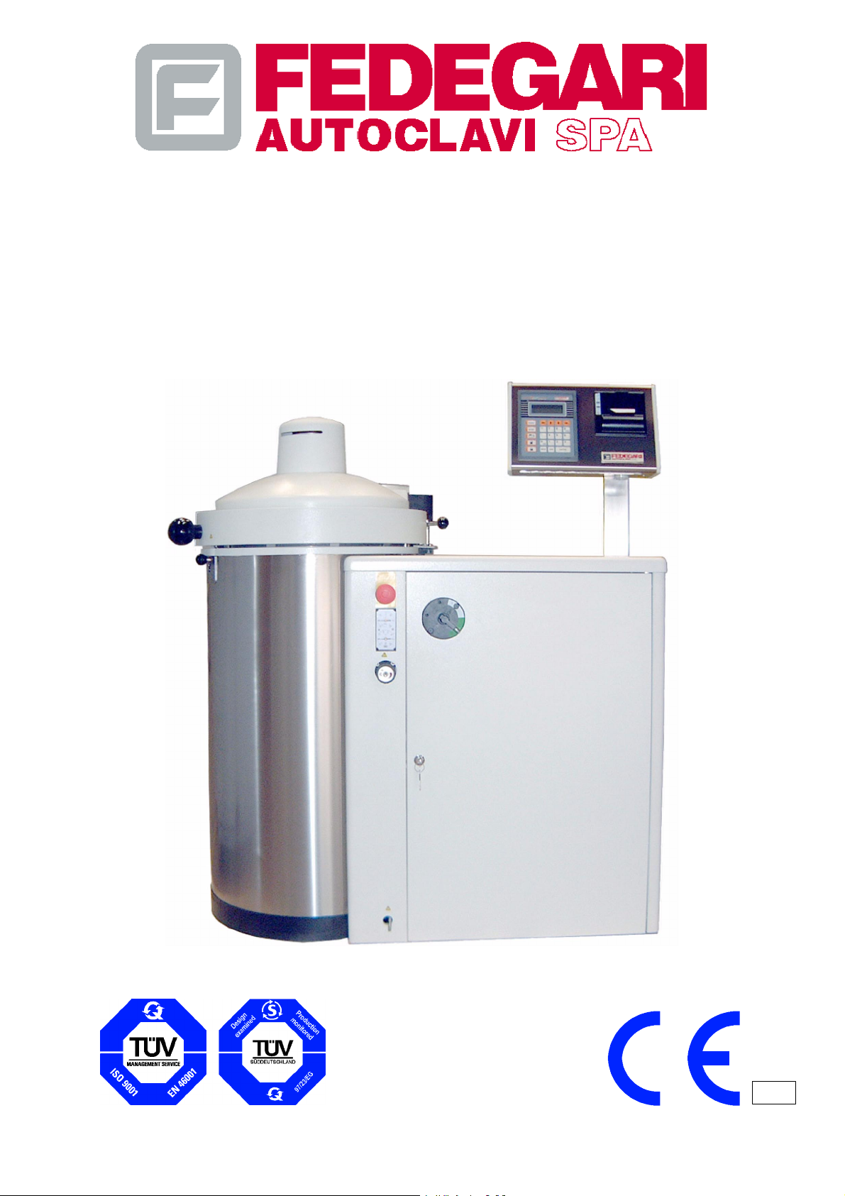
OPERATING MANUAL
STERILIZER MOD. FVA
Document Code: #68181 Rev.1
0123
Page 2

AUTOCLAVE
Model: FVA2 -- FVA3
THIS MANUAL’S INFORMATION REFERS TO THE MACHINE, COMPLETE WITH ALL OPTIONAL
FITTINGS. THE MACHINE CONFIGURATION DESCRIBED BELOW DEFINES THE OPTIONS
AVAILABLE DURING FINAL TESTS, BEFORE DELIVERY.
MACHINE CONFIGURATION:
F BASIC MACHINE
f
K10 STEAM GENERATOR
f K20 VACUUM PUMP
f K30 EFFLUENT COOLER
f K40 INTERNAL AIR ELECTROCOMPRESSOR
f K43 EXTERNAL AIR ELECTROCOMPRESSOR
f K50 AIR STERILIZING FILTER
f K51 NETWORK COMPRESSED AIR SUPPLY UNIT
f K52 QUICK COOLING UNIT
f K53 SPONTANEOUS COOLING
f K61 CHAMBER PRESSURE LEAK TEST
f K62 DECONTAMINATION CYCLE
f K70 STEAM SUPPLY DEFLECTION UNIT
f K80 ADDITIONAL HEAT PROBE
f K81 PROCESS PRINTER
f K82 KIT EN285--DATALOGGER
f HW1 SECONDARY RS232 SERIAL OUTPUT
f SW1 CONTROL FUNCTION FO
f T30 DEIONIZER
f SW2 CYCLE REPETITION
FEDEGARI Autoclavi S.p.A.
S.S. 235 km 8 -- 27010 Albuzzano (PV) -- Italia
+39 0382 434111 +39 0382 434150 http://www.fedegari.com
WARNING
The information contained in this document may be modified without prior notice.FEDEGARI does not
provide any kind of guarantee on this manual.FEDEGARI is not liable for any errors contained herein
and/or for any incidental/ consequential damageregarding the supply , performance or use of this manual,
This document’s information are our property. None of its parts may be photocopied, reproduced disclosed
in another language without FEDEGARI’s prior written consent.
-- I --
May 2001
#68181 Rev.1
Page 3

Model: FVA--HT
MACHINE CONFIGURATION:
F K10 STEAM GENERATOR
F K30 EFFLUENT COOLER
F K50 AIR STERILIZ ING FILTER
F K51 NETWORK COMPRESSED AIR SUPPLY UNIT
F K52 QUICK COOLING UNIT
F K61 CHAMBER PRESSURE LEAK TEST
F K62 DECONTAMINATION CYCLE
F K80 ADDITIONAL HEAT PROBE
F K81 PROCESS PRINTER
F HW2 HIGH PATHOGEN
F SW2 CYCLE REPETITION
This sterilizer is designed in such a way as to prevent any contamination hazard to the environment and the operators.
For this reason, the sterilizer operates as follows:
1. It does not extract the air from the chamber, since all filters, even high--retention ones, are useless in the presence
of small agents, such as prions.
2. It keeps in the chamber the condensate that forms during the process, until the sterilization has been completed;
however, the first condensate which may be produced is not sterile.
The steam + air mixture forming in the sterilization chamber is kept homogeneous by a fan positioned inside the
chamber. As a matter of fact, the air density (at the same temperature and pressure) is approximately 1.7 times higher
than the water steam density, and without this measure the air would stratify on the bottom of the chamber, resulting in
intolerable temperature gradients.
The temperature of the steam + water mixture forming in the chamber will depend on the selected sterilization
temperature.
The mixture pressure will consist of the addition of two factors:
1. The water steam pressure at the selected sterilization temperature.
2. The air pressure at the selected sterilization temperature.
If, for example, the sterilization process is carried out at 140_C:
-- factor 1 is 3,61 absolute bar (water steam pressure 140_C);
-- factor 2 can be calculated as follows: when the sterilizer is closed at room temperature (approx. 20_C), the
pressure of the air closed in the chamber is about the room pressure, i.e. 1,0 absolute bar. The air, however, heats
up at 140_C, increasing its pressure in the ratio of initial to final heating temperatures, and accordingly pressure
becomes:
1,0 x
140 + 273
20 + 273
=1,0x
413
= 1,41 absolute bar
293
-- The total pressure of the steam + air mixture in the chamber will be 138_C: 3,61 + 1,41 = 5,02 absolute bar.
The sterilizer is therefore designed to operate up to 4.70 rel. or manometric bar (i.e. above the atmospheric pressure),
up to 5.70 absolute bar.
-- II --
#68181 Rev.1
May 2001
Page 4
ADDITION AND CHANGE REGISTRATION
Name
function
PREPARED BY: IDO FAP 23/05/01
CHECKED AND
APPROVED BY:
Review Date Description
F.I.DT.00089.A.0.E.06.97 15/06/97 First issue, software version VC0001.0
F.I.DT.00089.B.0.E.01.98 19/01/98 Modifications in and additions to all Chapters
F.I.DT.00089.B.1.E.06.98 15/06/98
ING FAF 23/05/01
Name
acronym
Modifications in and additions to Paragraphs: 2.4.1. -- 3.3.1.
-- 3.3.2.
5.5.1. -- 5.5.2. -- 6.2.9. -- 8.3.3. 8.3.4.1. -- 8.4.1. -- 8.4.4.
Date
(dd/mm/yy)
Signature
Addition of Paragraph 8.4.5.
F.I.DT.00089.C.1.E.02.99 25/02/99 New version - - software VC0002.0 and VC0002.1
New version -- software VC0002.4
F.I.DT.00089.D.1.E.12.99 13/12/99
#68181 Rev.1 23/05/01 New software version: VC0002.9
May 2001
Upgrade software VC0002.5 (allow to imput new serial
number. -- es. NA0123ED)
-- II I --
#68181 Rev.1
Page 5

TABLE OF CONTENTS
1. FOREWORD 1.............................................................
1.1. PUBLICATION IDENTIFICATION 1..................................................
1.1.1. Allied documentation 1.............................................................
1.2. PUBLICATION OBJECTIVE 1......................................................
1.3. REFERENCES TO RULES AND STANDARDS 1.....................................
1.4. USING THE MANUAL 1...........................................................
1.5. UPDATES 2......................................................................
2. INTRODUCTION 3..........................................................
2.1. IDENTIFICATION 3...............................................................
2.2. SERVICING 3....................................................................
2.3. RISKS DERIVING FROM USING THE SOFTWARE 4.................................
2.4. SAFETY WARNINGS 4............................................................
2.4.1. General warnings 4...............................................................
2.4.2. Machine state 8...................................................................
2.4.3. Operators 9......................................................................
2.4.3.1. Operators’ qualification 9...........................................................
2.4.3.2. Personal protection means 10......................................................
2.4.4. Recommendations and precautionary measures to be adopted by the user 11............
2.4.5. Emergencies 11...................................................................
3. GENERAL INFORMATION 13................................................
3.1. GENERAL DESCRIPTION 13......................................................
3.1.1. Foreword 13......................................................................
3.1.2. Main components 13..............................................................
3.1.2.1. Sterilization chamber 15...........................................................
3.1.2.2. Cover and Sealing system 15.......................................................
3.1.2.3. Technical cabinet 16...............................................................
3.1.2.4. Electric system 16.................................................................
3.1.2.5. Electric board 16..................................................................
3.1.2.6. Plumbing and pneumatic plant 16...................................................
3.1.2.7. Operator panel 16.................................................................
3.1.2.8. Electronic process controller 17.....................................................
3.1.2.9. Main additional components (optional) 18............................................
-- IV --
#68181 Rev.1
May 2001
Page 6

3.1.2.10. Loading/unloading devices 22......................................................
3.2. SAFETY SYSTEMS 23............................................................
3.2.1. Opening/closing system 23.........................................................
3.2.2. Safety valves 25..................................................................
3.3. DATA SHEET 26..................................................................
3.3.1. Main dimensions and weights 26....................................................
3.3.2. Operational data and main performance 27...........................................
3.4. RECOMMENDED USE 28.........................................................
3.5. FORBIDDEN USE 28..............................................................
4. TRANSPORT, HANDLING, STORAGE 29.....................................
4.1. GENERAL WARNINGS 29.........................................................
4.2. TRANSPORT 29..................................................................
4.2.1. General information 29.............................................................
4.2.2. Transport instructions 29...........................................................
4.2.2.1. Packaging 29.....................................................................
4.2.3. Specific procedures 29.............................................................
4.2.3.1. Warnings 29......................................................................
4.2.3.2. Lifting the machine packaging 30....................................................
4.2.3.3. Handling on the installation site 30..................................................
4.3. STORAGE 31....................................................................
4.3.1. Short shut--downs 31..............................................................
4.3.2. Prolonged shut downs 31..........................................................
5. INSTALLATION AND DISMISSION 32........................................
5.1. ENVIRONMENTAL CONDITIONS FOR USE 32.......................................
5.2. SPACE REQUIRED FOR USE AND MAINTENANCE 32...............................
5.3. PACKING REMOVAL 32...........................................................
5.4. POSITIONING THE MACHINE 33...................................................
5.5. CONNECTIONS TO POWER SOURCES AND SERVICE NETWORKS 34...............
5.5.1. Hydraulic connections of the users 34...............................................
5.5.1.1. DEIONIZER options (T30) 35.......................................................
5.5.2. Wiring 36.........................................................................
5.6. INSTALLATION MONITORING 37...................................................
5.7. DISMISSION 37..................................................................
-- V --
May 2001
#68181 Rev.1
Page 7

6. USING THE STERILIZER 38.................................................
6.1. OPERATION DESCRIPTION 38....................................................
6.1.1. General information 38.............................................................
6.2. CONTROLS 39...................................................................
6.2.1. General information 39.............................................................
6.2.2. Control desks 39..................................................................
6.2.3. Display 40........................................................................
6.2.4. Keyboard 41......................................................................
6.2.5. Main switch 44....................................................................
6.2.6. Printer (optional) 44...............................................................
6.2.7. Datalogger -- Kit EN285 (optional K82) 45...........................................
6.2.8. Emergency button 51..............................................................
6.2.9. Control pressure--vacuum gauges 51................................................
6.2.10. Manual pressure relief valve of the chamber (not available on FVA--HT model) 52.........
6.3. ACCESS LEVELS AND OPERATING MODES 53.....................................
6.3.1. Access levels 53..................................................................
6.3.2. Operating modes 54...............................................................
6.4. OPERATING PROCEDURES 55....................................................
6.4.1. Warnings 55......................................................................
6.4.2. General information 55.............................................................
6.4.3. Sterilization programs 55...........................................................
6.4.3.1. Working parameters 56............................................................
6.4.3.2. Program parameters 61............................................................
6.4.3.3. General system parameters 67.....................................................
6.4.4. Operating phases 69..............................................................
6.4.4.1. Menu page access logic 69.........................................................
6.4.4.2. ”Step--by--step” and ”Cycle stop” functions 69.........................................
6.4.4.3. F0 70............................................................................
6.4.4.4. Opening/closing logic of the cover 71................................................
6.4.4.5. Printing function (if a printer is available) 71..........................................
6.4.5. Operating procedures and warnings 72..............................................
6.4.5.1. Switching on and initial checks 73...................................................
6.4.5.2. Panel functions and operation enabling 74...........................................
6.4.5.3. Program start 76..................................................................
6.4.5.4. Batch loading 78..................................................................
6.4.5.5. Process control 79................................................................
6.4.5.6. Batch unloading 83................................................................
6.4.5.7. Deactivation or switching off 84.....................................................
6.5. CONFIGURATION 85..............................................................
-- VI --
#68181 Rev.1
May 2001
Page 8

6.5.1. General Information 85............................................................
6.5.2. Program parameter configuration 85.................................................
6.5.3. Changing general parameters 87....................................................
6.6. CONTROL SYSTEM MAINTENANCE 88.............................................
6.6.1. General information 88.............................................................
6.6.2. Changing date and time 89.........................................................
6.6.3. Monitoring the operator panel 89....................................................
6.6.4. Autodiagnose 90..................................................................
6.6.5. Alarm List 91.....................................................................
6.6.6. Sterilizer data 91..................................................................
6.7. AUXILIARY FUNCTIONS 92........................................................
6.7.1. Transferring system regulation data 93...............................................
6.7.2. Managing the stored alarm list 93...................................................
6.7.3. Language select 94...............................................................
6.7.4. Modify password 94...............................................................
6.7.5. Delayed start 95..................................................................
7. ALARMS AND FAULT FINDING 98...........................................
7.1. ALARMS 98......................................................................
7.2. FAULT FINDING 101..............................................................
7.3. FAULT DETECTION PROCEDURES 102............................................
7.3.1. Autodiagnose functions 105........................................................
8. MAINTENANCE AND SERVICING 109........................................
8.1. GENERAL WARNINGS 109........................................................
8.2. FOREWORD 109.................................................................
8.3. PREVENTIVE MAINTENANCE 109.................................................
8.3.1. General information and warnings 109...............................................
8.3.2. Visual inspection 110..............................................................
8.3.2.1. Preliminary operations 110.........................................................
8.3.2.2. Inspection 110....................................................................
8.3.3. Cleaning 112.....................................................................
8.3.3.1. Cleaning the chamber 112..........................................................
8.3.3.2. Cleaning the chamber filter 113.....................................................
8.3.3.3. Cleaning the heat probe 114........................................................
8.3.3.4. Cleaning the operator interface devices 114..........................................
8.3.3.5. Cleaning the cover and the external cabinet 114......................................
8.3.3.6. Cleaning the batch transport baskets 114............................................
May 2001
-- VI I --
#68181 Rev.1
Page 9

8.3.3.7. Cleaning line filters 114............................................................
8.3.4. Scheduled performance tests 115...................................................
8.3.4.1. Checking the chamber safety valves and the steam generator, if any 115................
8.3.4.2. Checking the chamber manual pressure relief valve 115...............................
8.3.4.3. Checking chamber sealing (if vacuum pump is available) 116...........................
8.3.4.4. Checking chamber pressure (if pressurization with compressed air is available) 116.......
8.3.4.5. Checking the cover grommet 117....................................................
8.3.4.6. Checking compressed air plant tightness 117.........................................
8.3.4.7. Checking heat probe (Pt100) 117...................................................
8.3.4.8. Temperature check of the cover opening safety system 118............................
8.3.4.9. Checking the compressed air reducer (if the solenoid valve for compressed
air inlet is available) 118............................................................
8.3.4.10. Calibrating the heat probe 118......................................................
8.3.4.11. Calibrating the pressure transducer 120..............................................
8.3.4.12. Checking instruments with a control pressure gauge 123...............................
8.3.4.13. Checking the chamber internal temperature with control sensors 124....................
8.3.4.14. Checking print quality, paper amount and feed (if a printer is available) 124...............
8.4. TROUBLESHOOTING 125.........................................................
8.4.1. Replacing the operator panel battery 125.............................................
8.4.2. Clearing paper jams (if a printer is available) 125......................................
8.4.3. Replacing the sterile filter 126.......................................................
8.4.4. Replacing the PLC battery 126......................................................
8.4.5. Replacing the power cable 128.....................................................
8.4.6. Replacing fuses 129...............................................................
ENCLOSURES 132.................................................................
-- VI I I --
#68181 Rev.1
May 2001
Page 10

1. FOREWORD
1.1. PUBLICA TION IDENTIFICAT ION
The ”OPERATING MANUAL” is an official document issued by FEDEGARI AUTOCLAVI S.p.A. (hereinafter referred
to as FEDEGARI) and forms and integral part of the machine. It is identified by a document code printed on the cover,
to allow for its identification, traceability and reference.
FEDEGARI reserves the right to change this manual at any time and without notice.
1.1.1. Allied documentation
Main manuals and documents
-- Technical reference documents, including:
* Installation drawing;
* P&ID drawing;
* Instrument legend;
* Wiring diagrams.
1.2. PUBLICATION OBJECTIVE
This manual is addressed to the users of sterilizers belonging to the series mentioned in the heading. It includes the
information required to use the machine properly. Good performance and durability of this machine, as well as
operators’ safety and processed product protection, depend on compliance with this manual’s rules and instructions.
Read it carefully and comply with its requirements and instructions.
Its information is updated to the printing date.
1.3. REFERENCES TO RULES AND STANDARDS
This manual has been prepared in conformity with:
-- Enclosure ”I” to directive 89/392/CEE and amendments thereof.
-- UNI EN 292/2 -- 1992.
1.4. USING THE MANUAL
NOTE
Keep this manual as long as the machine is used.
Make sure that all updates are promptly included in the manual.
As it forms an integral part of the machine, it should always follow it, inside the firm where the
machine is used or elsewhere.
This manual consists of two sections. The first section, the pages of which are identified by Roman numerals (e.g. I, II,
III, IV...etc.), is composed by:
-- 1 --
May 2001
#68181 Rev.1
Page 11
-- the Title Page;
-- the addition and change registration;
-- the Table of Contents.
Through this section, the user can identify the publication and its update level. The table of contents allows to find the
desired topic in the manual.
The second section, the pages of which are identified by Arabic numerals (e.g. 1,2,3,...n), provides the sterilizer
operating and maintenance instructions. Read all this manual, page after page. Learn and remember all warnings.
As the operator should be qualified for using sterilizers, all general information and instructions they are acquainted
with have been omitted.
All operations require great care and caution. Throughout this manual, the following ”warnings” inform the user about
difficult and dangerous operations.
NOTE
Indicates important information pointed out outside the text.
WARNING
Indicates a condition in which lack of caution or wrong procedures are likely t o damage -- also
irreparably -- the sterilizer.
CAUTION!
Indicates a dangerous situation for people.
In addition to these general warnings, this manual includes other special symbols, printed throughout its pages,
similar to the symbols applied to the machines by means of plates and/or decalcomania in order to indicate dangerous
areas and behavior.
Before approaching the machine to start any operations and maintenance jobs, carefully read the above mentioned
warnings and instructions and understand them.
Carefully keep this manual. Handle it with care and do not damage its content, even partially.
The operator must promptly replace the manual or any lost, damaged or completely/partially illegible plates, stickers
etc. applied to the machine.
NOTE
Do not remove, tear or re--write this manual or its sections. In case of operations or situations other
than those described in this manual, do not hesitate to contact the manufacturer for any updates.
Keep the manual in a dry and cool place.
1.5. UPDATES
Any updates may be communicated to the machine owner using single sheets, complete with all instructions required
to add them to the manual.
Should the sterilizer be sold, its owner must notify FEDEGARI about all related references, so that the manufacturer
will be able to deliver any additions/updates to the new owner.
-- 2 --
#68181 Rev.1
May 2001
Page 12
2. INTRODUCTION
2.1. IDENTIFICATION
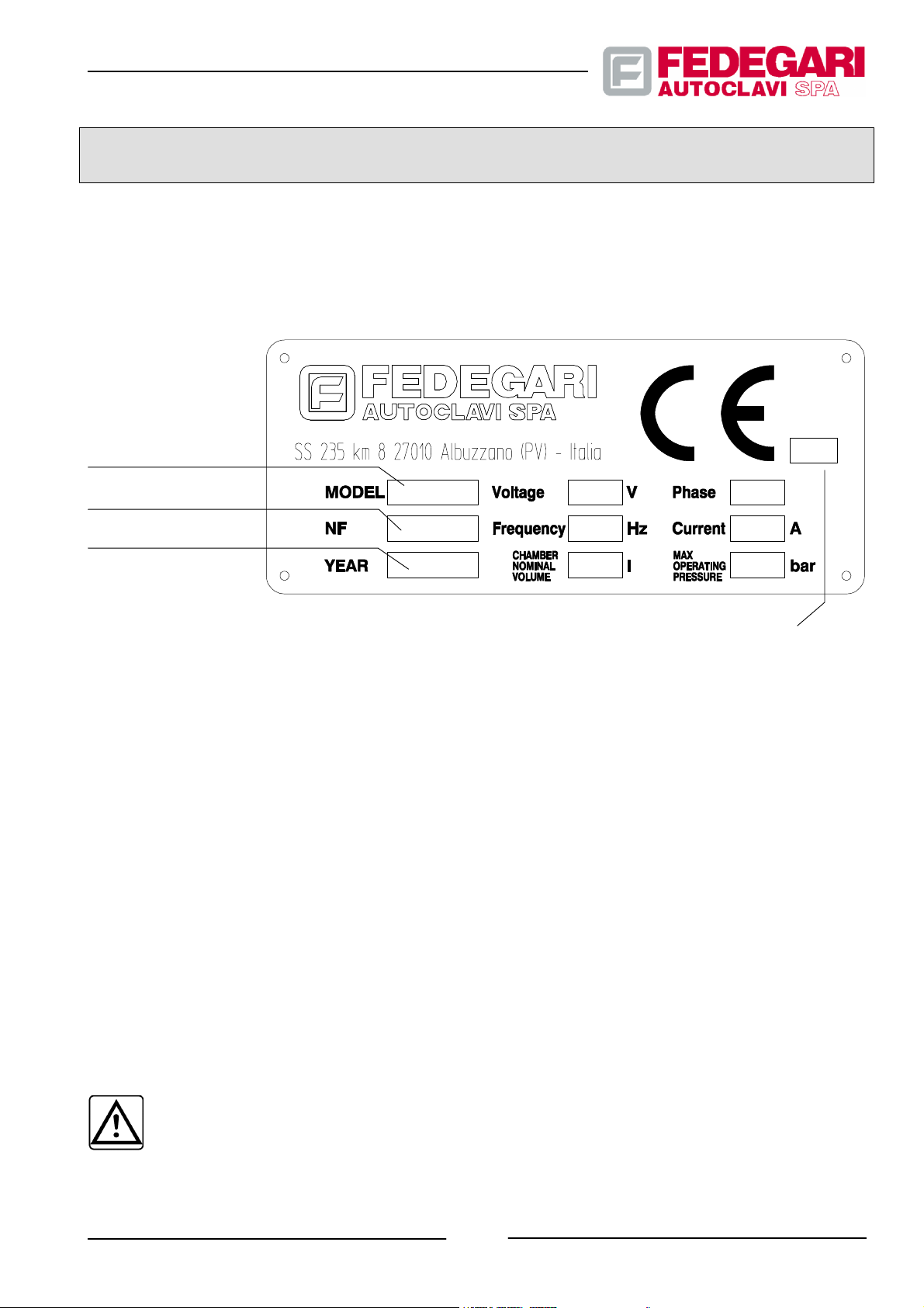
Figure 2.1 shows the facsimile of the sterilizer CE identification plate.
STERILIZER
MODEL
SERIAL NUMBER
YEAR OF FABRICATION
NOTIFIED BODY’S INITIAL
(MARKED ONLY IF THE MACHINE
IS A MEDICAL DEVICE)
Figure 2.1 -- CE identification plate
0123
2.2. SERVICING
FEDEGARI is always at its customer’s disposal, whether directly or indirectly through its agents/local dealers, for any
operations required. Suitable equipment and specialized personnel are available for overhaul and servicing. Please
ask FEDEGARI AUTOCLAVI S.p.A SS.235, km 8 -- 27010 Albuzzano (PAVIA) -- Italy, for the names and address of
FEDEGARI SERVICE CENTERS in Italy and abroad.
This machine is guaranteed according to the Sales Agreement General Conditions.
The guarantee will no longer be valid:
-- if the machine is repaired without the consent of the manufacturer or of FEDEGARI Service Centers ;
-- when using spare parts other than the original ones;
-- should the machine be used for any operations other than those recommended;
-- in case of non--compliance with this manual’s instructions.
WARNING
FEDEGARI cannot be held liable for any failures and operational faults due to non--compliance with
preventive maintenance suggested by the manufacturer and indicated in this manual.
-- 3 --
May 2001
#68181 Rev.1
Page 13

2.3. RISKS DERIVING FROM USING THE SOFTWARE
The use of the software supplied by Fedegari together with its products is licensed to the customer, who will be fully
responsible for it (see also the General T erms of Sale).
CAUTION!
Fedegari or its representatives cannot be held liable for direct/indirect damage deriving from using
the software, from its failures or the above mentioned license.
2.4. SAFETY WARNINGS
2.4.1. General warnings
CAUTION!
Most labor accidents are due to non--compliance with safety rules.
All operators using the sterilizer must know and comply with the rules mentioned in this manual and
on warning plates.
Always observe the rules recommended below.
CAUTION!
Some electrical circuits of the machine remain supplied also when the master switch is off (in the ”0”
position). These circuits are located inside the electrical board an d are adequately indicated.
CAUTION!
Do not inhibit the machine safety devices. When safety is not assured, all operations are allowed only
to FEDEGARI’s personnel, or, with the manufacturer’s authorization, to the user’s trained staff.
CAUTION!
Before using the sterilizer, ALWAYS check that the materials to be processed are compatible with the
cycles and steps of the sterilization program to be started.
Make sure that the mate rials are free of molecular instability risks which, during product handling or
processing, are likely to cause explosions.
CAUTION!
Do not perform any kind of jobs and changes on the machine and its fittings.
Do not modify the sterilizer parts in order to fit other devices.
In case of malfunctioning/accidents due to non--compliance with the above mentioned instructions,
#68181 Rev.1
-- 4 --
May 2001
Page 14

FEDEGARI shall not be liable for the related consequences.
Do not hesitate to contact FEDEGARI whenever changes to the machine are required.
CAUTION!
CAREFULLY position the heat probe used also as a safety device for chamber opening temperature,
according to the following instructions.
Pay attention to the temperature displayed as:
* when the heat probe is placed between -- not inside -- the bottles of one of the lowest batch layers,
the heat probe can detect the sterilization chamber temperature.
Therefore, always TAKE INTO ACCOUNT that the time required by bottle liquid to reach the
temperature displayed by the heat probe is directly proportional to the bottle volume.
For 50 cc bottles, the safety margin is 30° C (for larger bottles, this margin is to be increased) and
the chamber must be cooled at a temperature not below 40°C, so that the bottle internal
temperature is 70°C, which is an acceptable value.
* When placing the heat probe inside a bottle, plunged in its liquid, safety limits are not needed,
although the sample bottle could be broken during its processing.
In this case, the heat probe will indicate the chamber temperature instead of the bottle
temperature. Therefore, before opening the sterilizer, the operator MUST check that the heat
probe placed inside the chamber is indicating the temperature based on the safety margin
mentioned in the previous section (about 40°C).
CAUTION!
When extracted from the machine, bottles having an internal temperature of more than 70°C could
explode, thus jeopardizing the operators.
The maximum safety te mperature allowing to open the cover must be set at <70°C and parameter
”CHECK FINAL T” must be enabled by setting value ”1”.
CAUTION!
Thermal sterilization in the presence of low--boiling liquids (i.e. with steam tension higher than the
water tension at the same temperature) and/or liquids flammable in the air (i.e. characterized by a
ceiling of concentration in the air above which a fire may propagate) involves two kinds of hazard.
* At the temperatures typical of thermal sterilization (i.e. at least 105°C) a low--boiling liquid can
develop such a high pressure that the safety valve opens, letting any gas and/or steam out of the
sterilizer, or preventing the correct performance of the sterilization process. For example, the
presence of alcohol in a closed room causes a partial pressure, in the aeriform phase, of approx.
4.5 absolute bar at the traditional temperature of 121°C. This pressure depends only on
temperature and is not affected by the quantity of alcohol. When the regulation of a s aturated
steam ste rilization occurs ”in temperature”, at 121°C, the pressure tends to reach approx. 6.5
absolute bar, and the safety valve opens well before reaching this value. When the sterilization is
regulated ”in pressure”, the pressure developed by the low--boiling liquid simulates the
May 2001
-- 5 --
#68181 Rev.1
Page 15

reaching of the regulation pressure, preventing the supply of steam to the chamber; the
temperature reached at the regulation pressure (3.50 absolute bar in case of decontamination
cycles with Fedegari FOB and FVA sterilizers) is not 121°C, being just above 100°C. The process
may indefinitely stop in the heating phase. Therefore, the presence of any low--boiling liquid may
result in the hazardous release of contaminated material from the chamber or in the impossibility
to carry out the sterilization.
* The eventual flammability of the liquid involves, of course, a fire hazard. The concentration of
flammable vapors in the air, as necessary for ignition, decreases based on temperature, while
the true concentration increases according to it. In most cases, a fire may break out due to the
level (even negligible) of static electricity entering with the vapor or, most frequently, with the
cooling air. Also in those cases that, at present, are well--known, the damage has been limited to
the interior of the sterilizer (that, of course, is shut--down), though it cannot be denied that the
possible opening of the safety valve may propagate fire also outside it. A similar hazard is
present when vacuum is applied at the end of the sterilization process. The flammable mixture is
sucked by a machine not meant for it and any cause of firing may have serious consequences,
that cannot be calculated.
CAUTION!
Before starting a sterilization cycle, make sure that the manual pressure relief valve is perfectly
closed.
CAUTION!
C02 fire--fighting means are recommended in order to provide preventive protection.
WARNING
Always assure that:
* the supply voltage to the sterilizer is constantly kept within ±10% of the nominal value required.
* The compressed air pressure to the sterilizer pneumatic circuits is stable, within ±10% of the
nominal value required.
* the saturated steam pressure oscillation for the sterilization chamber is kept within ±10% of the
nominal values required.
* the pressure of water feed line to the sterilizer is kept within ±10% of the nominal values required.
Failure to comply with these recommendations may cause malfunctions during the sterilization
cycles and damage the machine.
WARNING
Do not use alcohol, petrol, other solvents or acid reaction substances for cleaning or washing the
chamber or the sterilizer components, as they are likely to attack stainless steel surfaces and
#68181 Rev.1
-- 6 --
May 2001
Page 16

elastomer parts.
Use water, also slightly diluted with neutral detergents, according to this manual’s maintenance
instructions.
CAUTION
To avoid cuts during maintenance of the air circulation fan in the sterilization chamber, do not
disassemble the fan and motor protections unless the plant is completely isolated from power
supply sources.
WARNING
For any kind of processes, es pecially in case of manual operations or dangerous processes (e.g.
decontamination), Fedegari guarantees the sterilization carried out by its machines provided the
process manager authorizes proper performance of all cycle phases envisaged for the product, by
signing the document printed by the sterilizer control system for approval.
CAUTION!
Do not use the sterilizer and its fittings to perform jobs other than those permitted and specified in
this manual.
CAUTION!
These sterilisers are not electromedical devices.
If they are installed near medical or surgical operation areas, they must never be placed at less than
2.0 metres from the patient for the entire period o f the operation.
May 2001
-- 7 --
#68181 Rev.1
Page 17
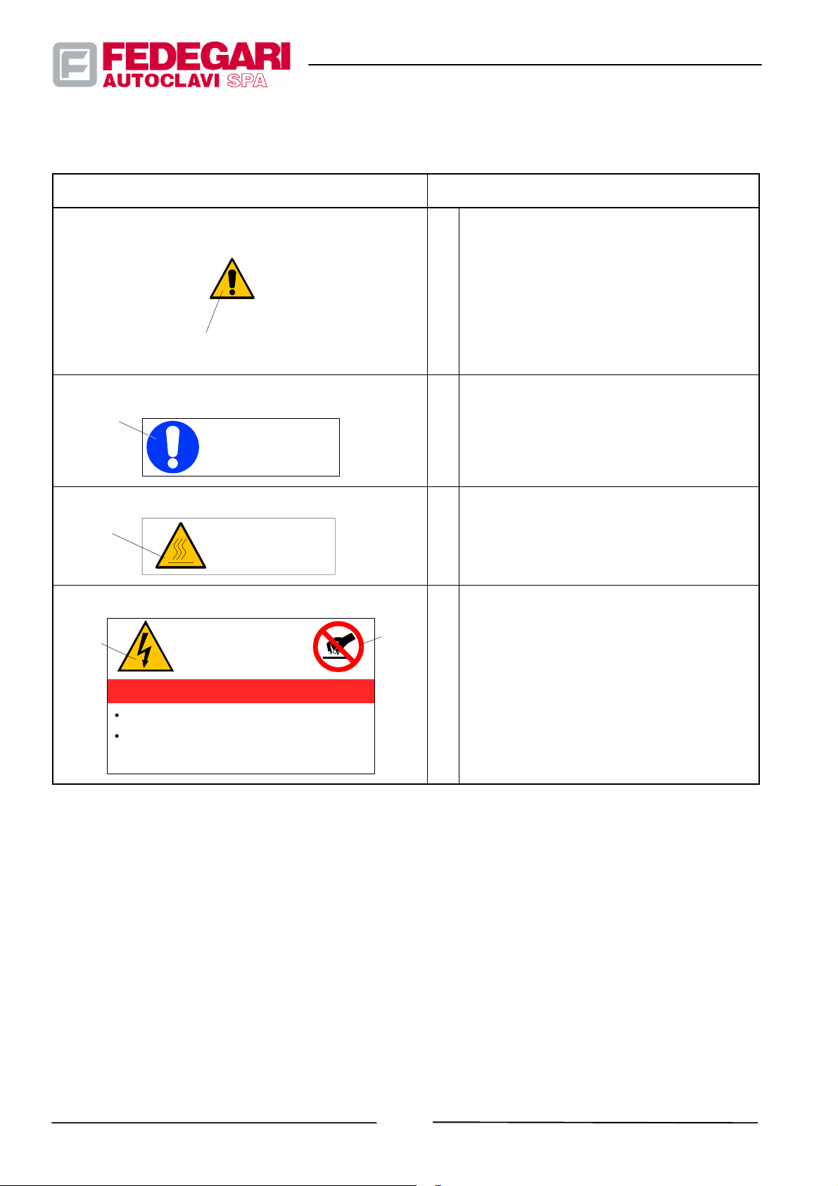
Figure 2.2 shows the warning plate position on the machine, pointing out any potential dangers.
Bleu
Yellow
Symbol/Plate name
General danger
Yellow
heck safety valve
on a periodical basis
WARNING
CHECK EVERY MONTH
THE SAFETY VALVES
EFFICIENCY
Hot surfaces
HOT
SURFACES
Plate position
1
USERS
SAFETY VALVE(S) VENT PIPE
2
COVER OPENING/CLOSING KNOB --
3
MASTER SWITCH
4
MANUAL PRESSURE RELIEF VALVE OF
5
THE CHAMBER
CHAMBER’S PRESSURE RELIEF PIPE
6
1
INSIDE THE TECHNICAL CABINET PANEL
2
AT THE REAR OF THE ELECTRICAL
BOARD
3
REAR PANEL NEAR THE SAFETY
VALVE(S) VENT PIPE
MACHINE CASING
1
AUTONOMOUS STEAM GENERATOR
2
(with option K10)
Electrical hazard
Yellow
Red
WARNING
1
DO NOT OPERATE ON LIVE
ELECTRIC EQUIPMENT
HOWEVER SPECIFIC AUTHORISATION MUST BE
OBTAINED FROM THE PERTAININGAUTHORITY
NOT LESS THAN TWO PERSONS MUST OPERATE IN
DANGEROUS C ONDITIONS
DO NOT START WORK WITHOUT HAVING
PERFORMED THE NECESSARY PRECAUTIONS
ELECTRICAL BOARD
Figure 2.2 -- Plates indicating potential dangers
2.4.2. Machine state
This machine allows for three different operating modes.
The first one (USE) allows to give the machine simple orders, while checking it in full safety, from its starting to process
completion, as well as to obtain the reports and/or messages confirming successful process performance.
The second operating mode (CONFIGURATION) allows to reconfigure the machine applications (sterilization
programs), while defining the general parameters controlling the activities and functions common to all sterilization
processes.
-- 8 --
#68181 Rev.1
May 2001
Page 18

The third operating mode (MAINTENANCE) includes all operating modes allowing to service and/or control (also ” ON
LINE ”) several software functions and the functional operating logics controlling the sterilizer.
2.4.3. Operators
When analyzing the works described in this manual, concerning the machine life cycle steps, FEDEGARI has taken
into account the operator’s qualities.
2.4.3.1. Operators’ qualification
Please find below a profile about the professional qualities required to each operator using the sterilizer.
The operator:
-- Must know the physical and chemical principles concerning gas, fluid and liquid dynamics during sterilization
processes;
-- Must be acquainted with environmental and behavioral problems, to protect the environment and other products
from microbiological and particulate contamination;
-- Must thoroughly know the operating principles of the machine, its structure, main blocks as well as the allocation of
the control units allowing to disconnect the machine from its main supply sources;
-- Must be properly trained for all operations required to start and control the plant and able to record the sterilization
data, also referring to the workmanlike manufacture rules in force in the country where the machine is used;
-- Must be properly trained to evaluate all events occurring during the sterilization cycle;
-- Must be properly trained to evaluate any alarms activated during the cycle;
-- Must be properly trained for stopping the machine in case of an emergency (also concerning the batch);
-- Must be properly trained and able to perform the preventive and corrective maintenance required for operator
interface performance.
CAUTION!
This recommended profile is to be integrated with other professional skills required by the rules in
force in the country where the machine is used.
May 2001
-- 9 --
#68181 Rev.1
Page 19
2.4.3.2. Personal protection means
Based on the batch to be processed, the operator must protect his body against the direct or indirect influence of
chemicals (whether organic or not) or microbiological elements (e.g. viruses, bacteria), forming the batch to be
sterilized or aggregated to it.
These substances can be noxious by contact, inhalation or contamination.
Always wear suitable protection means, such as masks, suits, gaberdines, gloves, protective glasses, footwear, boots
etc...
CAUTION!
The operator MUST be allowed to check the batch before its delivery, to verify the type of material
included.
CAUTION!
The operator must wear suitable work clothing, to be protected against chemical, physical and/or
microbiological risks, deriving from contact with a wide range of materials, including gases and
liquids.
The work clothing material and structure must be fit for protecting the operator against any
contact/contamination dangers.
The buyer is responsible for the use of highly protective means suitable for the type of product to be
processed, in compliance with the rules in force in the country where the machine is used.
WARNING
All personal protection means must permit the operator t o move freely in order to carry out the
necessary operations and to properly see with the best angulation and limited sight distortion.
Use only certified protection means. All protection means must be carefully used and kept (e.g. wear
them correctly, tighten the related closing systems, replace mask filters etc.).
WARNING
Personal protection means are sometimes recommended in order to protect the processed product
against contamination (e.g., during unloading operations).
To treat products free of chemical or microbiological risks:
-- Wear a waterproof cotton one--piece suit or other work clothing, allowing for good transpiration and covering the
whole body, except for your face;
-- Wear suitable, comfortable shoes, for proper mechanical protection from spilled liquids;
-- Wear light, protective glasses against sprays. They should not be made of glass, without fragmentation danger,
transparent with the best refractive index, visual angulation and low distortion.
#68181 Rev.1
-- 10 --
May 2001
Page 20

2.4.4. Recommendations and precautionary measures to be adopted by the user
The user must fit the installation area with suitable lighting devices, complying with safety and accident prevention
rules.
The user must assure that the area before the sterilizer is provided with an antislip flooring, in aggregate or polymeric
materials, easy to wash and fit for chemical and thermal disinfection.
The floor must be fit for any processing, according to the products to be sterilized.
Clear and legible warnings must be installed near the work station, to prevent unauthorized personnel from entering
the work area.
Before delivery, the user must train its operators and make sure that they are acquainted with the machine and able to
carry out the necessary operations, according to the skill profile mentioned in section
2.4.3.1.
2.4.5. Emergencies
The user must fit the area with proper fire--fighting stations.
CAUTION!
C02 fire--fighting means are recommended in order to provide preventive protection.
In an emergency, the operator must be free to reach the main switch and the primary feed shut--off valves.
Electric system black--out
In case of black--out, the main switch is activated to isolate all downstream elements.
All processes started before the black--out will be stopped.
When the electric power is restored, after resetting the main switch, the sterilizer enters an emergency state, waiting to
receive a manual control which brings the sterilization process to the cycle end phase or to the
Emergency--Decontamination phase, after an electrical blackout has occurred, during the ”Heating” or ”Sterilization”
phases, in the Decontamination Program.
The sterilization chamber features a pneumatic cover seal and the related devices, which assures chamber tightness
also in case of pneumatic or power failure.
Depressurizing the door pneumatic seal takes more than depressurizing the chamber.
The atmospheric pressure inside the chamber, caused by sealing failure due to a black--out, is reached after at least
20 hours, based on the machine maintenance level.
Pneumatic, steam and water supply failure
All supply line failures are detected by proper sensors and could considerably increase the time required to complete
the steps of the process in progress.
The sterilizer enters an emergency state, waiting for the reset of suitable parameters.
May 2001
-- 11 --
#68181 Rev.1
Page 21

Emergency stop
Press the ”EMERGENCY” mushroom--head push--button to stop power supply to the machine by means of the main
switch. Refer to the instructions of item ”Electric system black--out”.
#68181 Rev.1
-- 12 --
May 2001
Page 22

3. GENERAL INFORMATION
3.1. GENERAL DESCRIPTION
3.1.1. Foreword
FV A vertical steam sterilizers are flexible and high--performance small--sized semiautomatic machines for
sterilization processes to be carried out in laboratories and hospitals (where they are not use as production
equipment).
3.1.2. Main components
The sterilizer (see Figure 3.1) consists of the following main components:
-- Sterilization chamber;
-- Cover and related sealing system;
-- Technical cabinet complete with a shutter covering the electrical board;
-- Electric system;
-- Hydraulic and pneumatic installations;
-- Operator panel;
-- PLC electronic process controller console;
-- Additional components (optional);
-- Fittings for product loading/unloading;
May 2001
-- 13 --
#68181 Rev.1
Page 23
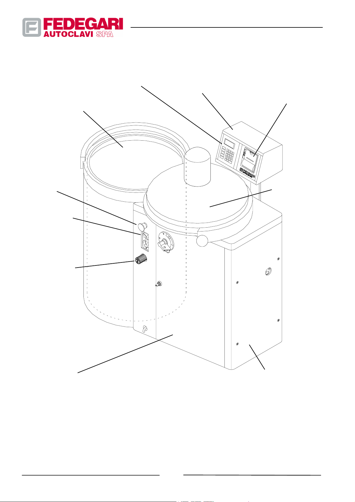
Sterilization chamber
Operator panel
Electronic process
controller
Printer (K81)
or
Kit EN285 Datalogger (K82)
Emergency
pushbutton
Vacuum--pressure
gauges
Manual Valve for
pressure discharge
in the chamber
(not present for
model FVA--HT)
Cover and
relevant sealing
system
Switchboard panel
#68181 Rev.1
Technical cabinet
Figure 3.1 -- Main components of the sterilizer
-- 14 --
May 2001
Page 24
3.1.2.1. Sterilization chamber
The pressurized sterilization chamber features a cylindrical section and a vertical axis, and houses the material to be
processed. The purge system on its bottom collects the condensate to be drained. The chamber is in AISI 316Ti gloss
finished steel with Ra < 0,19 mm surface roughness
3.1.2.2. Cover and Sealing system
Cover
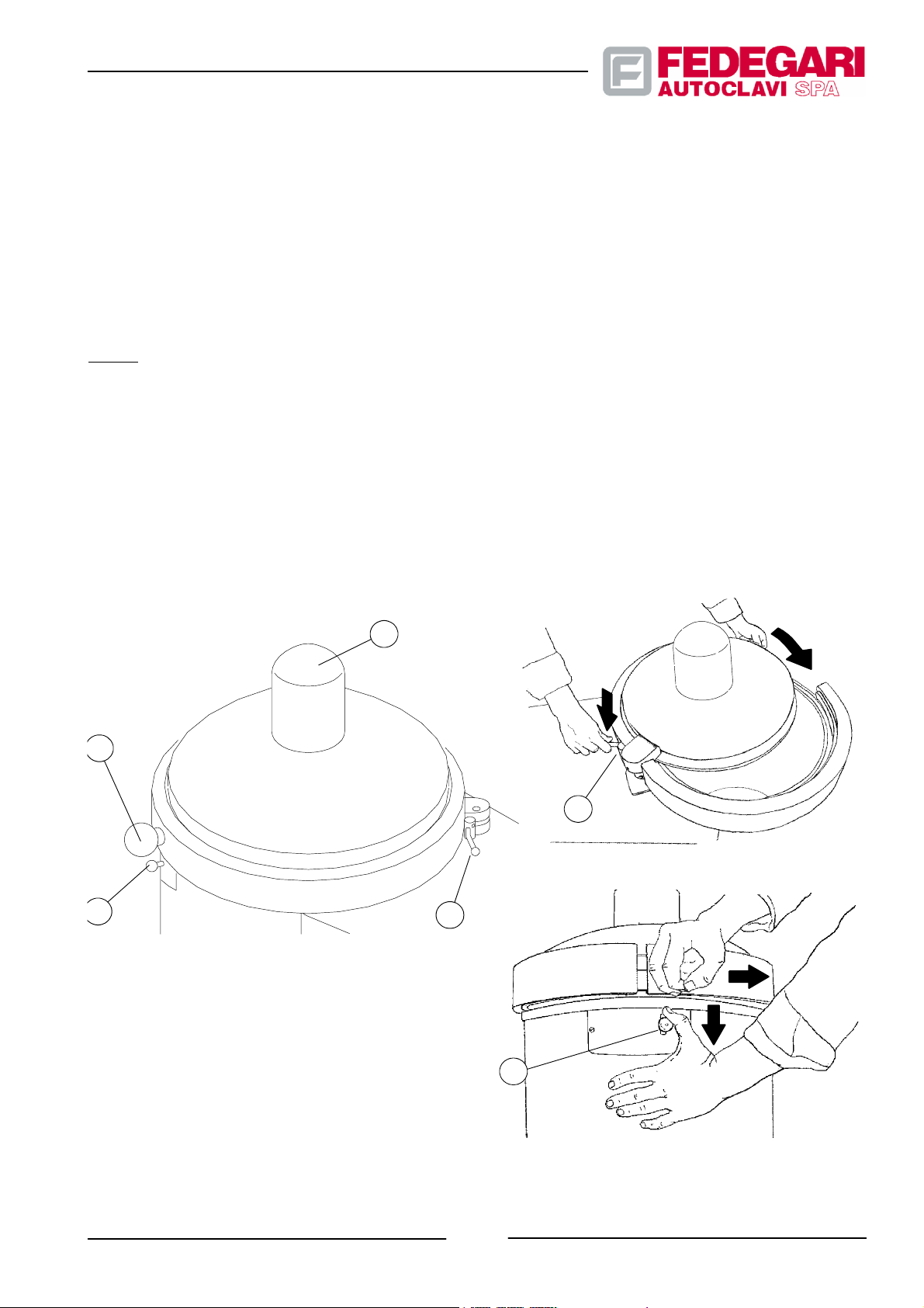
The horizontally rotating cover (see Figure 3.2), in position ”Closed door” is coupled with the chamber through a ”C”
band which, even under minimum pressure inside the chamber prevents the cover from rotating and opening.
The chamber cover is fitted with a horizontally rotating knob (pos. 1) for easy opening and closing,. When closing the
cover, a safety lever (pos. 2) positioned on its top, is moved by the operator with both hands, to prevent damaging his
fingers. Once closed, the cover can be opened by lowering the lever (pos.3), which releases a safety device.
The particular profile of the cover allows you to install a special (optional)fan, with magnetic joint (pos. 4), to be used for
specific phases of batch cooling.
1
3
LEGEND
1. Knob
2. Safety lever
3. Cover release lever
4. Fan (optional)
4
2
2
3
May 2001
Figure 3.2-- Cover closing system
-- 15 --
#68181 Rev.1
Page 25

Sealing system
The sealing system consists of a silicone rubber seal. To seal the sterilization chamber when the cover is closed,
supply the seal housing with compressed air. The seal is pushed outwards and pressed against the cover.
3.1.2.3. Technical cabinet
The external cabinet, in polyurethane resin and featuring an AISI 304 stainless steel frame, includes the hydraulic,
electric and pneumatic installations, the process electronic controller components and, according to the machine
configuration, the autonomous steam generator, the vacuum pump and other optionals.
3.1.2.4. Electric system
The sterilizer electric system complies with EN61010--1, EN61010--2--041, EN60204--1 European standards.
The electric circuit is fitted into a suitably ventilated box, which can be easily reached from the machine front.
The plant includes all control lines of electrohydraulic or electropneumatic actuators of the motors, of the electronic
process controller,of the autonomous steam generator,if any. The plant connects the process controller to all sensors
and transducers (e.g. pressure switches, heat probes etc.), as well as to the operator interface devices. It also
provides for the primary feed line and its protection plant.
3.1.2.5. Electric board
The electric board is located in front of the machine cabinet and lodges the main electric and electronic
feeding/disconnecting devices, as well as the distribution equipment, including the main switch. This switch features a
release coil allowing to open it, should the protection devices be activated, and to disconnect power supply to the
machine.
3.1.2.6. Plumbing and pneumatic plant
The plumbing and pneumatic plant (see the P&ID scheme) consist of pipes, solenoid valves, pneumatic and
electropneumatic valves. The hydraulic plant is in AISI 316L stainless steel and is fitted with small sanitary flanges,
with the related closing clamps for connecting each element and suitable elastomer seals.
3.1.2.7. Operator panel
The Operator Panel, located on the top of the cabinet, consists of a LCD 4 lines, 20 columns display and of a
membrane keyboard, through which the operator manages the interactive dialogue with the machine. It also features
RAM , with emergency power supply and FLASHEPROM for the user program, a serial port for the printer interface
and a RS 232 serial port for PLC interfacing.
#68181 Rev.1
-- 16 --
May 2001
Page 26

3.1.2.8. Electronic process controller
The electronic process controller consists of a programmable logic controller (PLC) which, together with specific
hardware blocks and other electronic equipment, controls the machine as well as all operations regarding the
interactive dialog with the operator.
It features 16 digital inputs/outputs, RS232 serial port for interfacing with the operator’s panel, RAM with emergency
power supply. The controller can use EPROM or EEPROM and features another RS232 serial port to transmit the
cycle data to an outer system (master), with a well--defined ASCII protocol.
The control software is certified according to IEC1131--3 standards.
The controller:
-- manages the dialogue with the operator through the interface devices;
-- controls the hydraulic/pneumatic plant actuators;
-- detects the system logics from the field (electric and hydraulic/pneumatic plant), based on the confirmation of set
activations;
-- detects the analog values of pressure and temperature measurements carried out, through specific modules
converting the analog signal from temperature and pressure sensors into a PLC--readable digital signal.
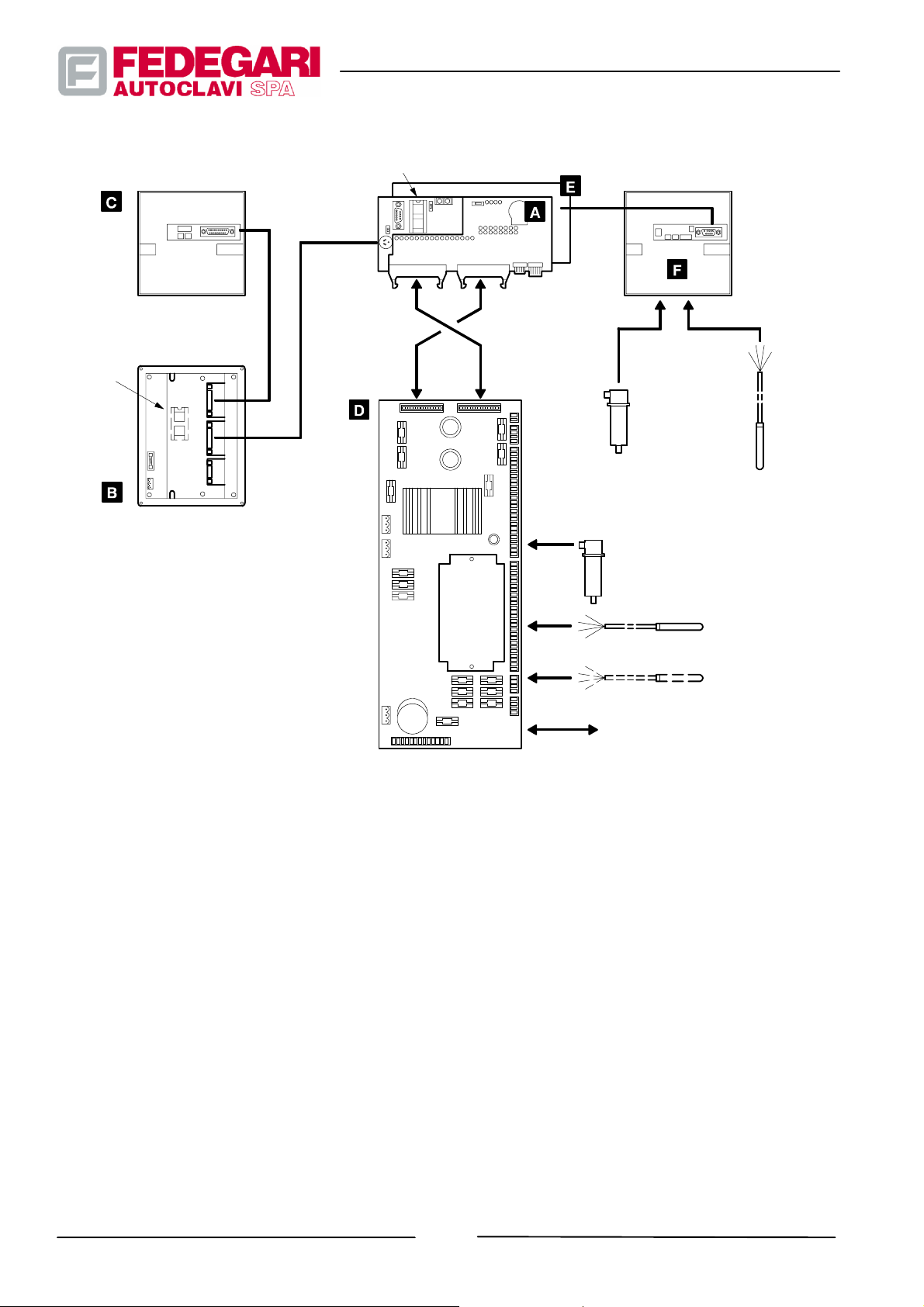
The process controller consists of the following units:
A PLC Matsushita FP--M--C32TC 5K--DC24V;
B Operator panel EXOR R&D T--line TCP01R--04--0245;
C Printer CUSTOM FT190SP;
D Module TECNA ADPLC/F32, converting analog signals into digital signals, with a minimum of 2 digital input and
output lines, for the direct reading of a 420 mA sensor and of two 4--wire heat probes Pt100.
E Expansion card provided with 12 inputs and 8 digital outputs;
F Datalogger CUSTOM FT190DL (K82).
Figure 3.3 shows the functional connections between the main blocks forming the process controller.
May 2001
-- 17 --
#68181 Rev.1
Page 27
PRINTER
(optional K81)
RS232
EPROM
EXPANSION
(optional K82)
DATALOGGER
(optional K82)
EPROM
OPERATOR
PANEL
RS232
16 16
IN OUT
OUT IN
MASTER
BOARD
PLC
PRESSURE
TRANSDUCER
4- -20 mA
(optional K82)
PRESSURE
TRANSDUCER
4--20 mA
4--WIRES PT100 HEAT
PROBES
(optional K80)
ANALOG/DIGITAL SIGNALS
FROM/TO
THE FIELDS
Pt100 4 WIRES
HEAT PROBE
(optional K82)
Figure 3.3 -- Process electronic controller--functionals connections
3.1.2.9. Main additional components (optional)
Main optional components:
-- Steam generator;
-- Va cu um pu mp ;
-- Effluent cooler;
-- Air electrocompressor;
-- Air sterilising filter;
-- Network compressed air supply unit;
-- Quick cooling unit;
-- Spontaneous cooling;
#68181 Rev.1
-- 18 --
May 2001
Page 28

-- Pressurized chamber leak test;
-- Decontamination cycle;
-- Steam supply deflection unit;
-- Additional heat probe;
-- Process printer;
-- Control function F
-- Secondary RS232 serial output;
-- Datalogger;
-- Deionizer.
;
0
Steam generator (K10)
The steam generator is installed when no saturated steam is available to feed the sterilizer, or when the quality of the
available steam is poor. The steam generator consists of pressurized reservoir D001, in AISI 316 stainless steel,
supplied with deionized water evaporating by means of three electric heating elements RX02 fitted on the top of the
reservoir. The loading of deionized water, supplied by the feed network and by a proper container through an electric
pump PA 0 1 , is controlled by solenoid valve E009, which opens pneumatic valve S009. Check valve R004 prevents
water from flowing to the pump. Pressure switch P004 detects pressure inside the generator, checks the heating
element power supply and warns the process controller when the pressure reached allows to supply the chamber.
Sensors L001 and L002 detect the water level inside the pressurized body.
The steam generator is also fitted with the following devices, for the pressurized reservoir operational safety:
-- Manual discharge valve V004;
-- Safety valve Y002;
-- Pressure gauge M003 detecting reservoir D001 pressure, clearly visible to the operator;
-- The rmo sta t T002, controlling the heating element temperature and signaling dry operation;
-- The rmo sta t T003, if required, checking the generator maximum temperature (TÜV).
Vacuum pump unit (K20)
It consists of a liquid ring pump PV01, fed by the network water. Water enters the pump through solenoid valve E011
and is regulated by valve V003.ValveV007 adjusts the air ballast necessary to the vacuum pump through the air
intake. Solenoid valve E011 opens when the motor is energized.
The pump is used to create continuous as well as discontinuous (impulse) vacuum in the sterilizer chamber.
This pump is required whenever air cushions in the batch could prevent its sterilization, as well as for product drying.
Effluent cooler (K30)
Effluent cooler W001 consists of a small mixing reservoir, fed by network water.The drain line condensate and gases
are sent to the reservoir before being discharged outside the machine. The cooling system is regulated by thermostat
May 2001
-- 19 --
#68181 Rev.1
Page 29

T004 and solenoid valve E001, located on the network water feeding line. The cooler is used in order to lower the
effluent temperature (up to 60_C) before letting it outside the sterilizer.
The cooling unit must be fitted whenever low temperature effluent is required, e.g. when the regulations of the
installation site do not allow for high--temperature effluent, or when the drain lines connected to the sterilizer are in
plastic material, which is likely to be damaged by high temperature.
Internal air electrocompressor (K40)
It can be fitted into the machine cabinet, to be used when no network compressed air is available.
The electrocompressor model and the related plenum chamber must be chosen based on the machine configuration.
If the sterilizer is not used to process liquids, compressed air is only needed to feed the cover seal and the pneumatic
valves. A 2 liters plenum chamber is sufficient to guarantee proper operation.
External Air electrocompressor (K43)
When the machine is used to carry out sterilization processes requiring compressed air, an external compressor must
be installed featuring a plenum chamber with more than 10 liters capacity.
Sterilizing filter for air (K50)
The air filtering unit consists of a filter F007 which can be sterilized in the sterilizer, with 0,22 mm retention, fitted in a
plastic container.
Network compressed air supply unit (K51)
This unit consists of solenoid valve E010 and pressure reducer VR02, which supplies the chamber with sterile
compressed air. This unit must be installed on the sterilizer when the batch to be sterilized requires an air
counter--pressure on completion of the sterilization process.
Quick cooling unit (K52)
The quick cooling unit basically consists of a magnetic fan CV12 and a heat exchanger located in the cover concavity.
They are installed so that the sterilization chamber volume is not reduced. The fan coupled to the motor ME12 through
a suitable magnetic joint must assure air circulation inside the chamber. Air is cooled when coming into contact with
the surface of the heat exchanger, supplied by network water. This procedure allows to reduce the liquid cooling time
and to increase the sterilizer performance. The quick cooling unit is recommended whenever the sterilizer is used to
process heat--sensitive liquids, in particular when they are stored in large bottles.
Spontaneous cooling (K53)
This option allows the ”Slow spontaneous cooling” of the load.
It requires the use of load interception electro--valve E007, that during the ”Spontaneous cooling” phase remains
closed until the pressure inside the chamber is lower than/equal to the average of maximum and minimum balancing
pressures.
The opening of the valve allows the discharge of the condensate produced during the cooling phase. The phase ends
-- 20 --
#68181 Rev.1
May 2001
Page 30

as soon as the target Temperature is reached.
During the ”Spontaneous cooling” phase, the pressure inside the chamber reaches balancing pressure values
spontaneously, without creating a pressure drop that is likely to damage the batch, if consisting of liquids contained in
reservoirs.
NOTE
The presence of option K51 ”Newtork compressed air supply unit” or option K52 ”Quick cooling
unit” (including K51), disables the effect of option K53 ”Spontaneous cooling”, that in these cases is
not enabled.
Pressurized chamber leak test (K61)
This option is used to perform the pressurized chamber leak test. It consists in shutting--off the discharge, usually
connected to the chamber through a calibrated orifice. This test can be performed as an alternative to vacuum leak
test in sterilizers lacking the necessary equipment. To carry out the pressure leak test, the machine must be fitted with
the air supply unit in counterpressure (K51).
Decontamination cycle (K62)
This cycle is installed on the machine in order to sterilize products involving microbiological pollution risks. During the
sterilization phase, start solenoid valve E071 to let saturated steam in, either through the chamber purge system or
directly through S008. The chamber and the purge system must have the same temperature. Solenoid valve E007 is
closed until completion of the sterilization process. Therefore, the sterilization chamber batch must not be removed
until the process is completed, i.e. when the chamber content has been sterilized. The maximum allowed temperature
is 121°C, equal to a 3.4 bar pressure with air/steam mixture.
Steam supply deflection unit (K70)
This device allows to selectively feed a sterilizer featuring an autonomous steam generator (K10), also with network
steam. The operator enters a process controller parameter for manually deviating a three--way valve V009 inside the
sterilizer technical cabinet.
Additional heat probe (K80)
This Pt 100 heat probe T005 is identical to that fitted on the sterilizer chamber. It can be connected to the process
controller, which will provide for the second temperature measurement, to be printed with the first one, or to an
optional external recorder.
Process printer (K81)
It is an alphanumeric printer installed next to the operator interface, in order to print detailed process documents. The
printer is provided with a 200 dpi thermal printing mechanism, uses 57.7mm wide paper and is connected to the
controller through a RS232 serial output.
Secondary R S232 serial output (HW1)
This option consists of a special software version loaded on the process controller, which enables the second PLC
RS232 serial output. It can be used to download in real time all data of the process in progress to a remote PC, in ASCII
format, or to connect a remote PC featuring the Fedegari software CVB- -LINK.
May 2001
-- 21 --
#68181 Rev.1
Page 31
Control function F0 (SW1)
For all applications requiring a handling of the F0 value accumulated during the process, instead of regulating
sterilisation based on a fixed time; you may obtain an handling of the F0 value accumulated during the process,
through the selection of proper parameters. The software begins calculating the Fo values starting from 100°C.
Datalogger (K82)
This device is used for the digital recording of analog signals, and is installed as on option for printing process data
(time, temperature and pressure) on thermal paper. Both the data loaded through the serial port and the data acquired
by the datalogger through its sensors (heat probe Pt100 and pressure transducer -- optional), in recording mode, are
considered for printing.
Deionizer (T30)
If the network water available for supplying the steam generator is too hard, in order to ensure better performance and
less frequent maintenance jobs, we recommend that you install a deionizer.
This group is mainly made up of a cartridge of mixed bed resin (8.5 l), that can change its tone based on its progressive
emptying. Once empty, the cartridge must be replaced with a new one, containing regenerated resin; lhe replacement
takes a few minutes and does not require any specific experience.
This model allows the treatment of approx. 750 l of water (with a new cartridge), for an output of 30 l/h; if the water
pressure at the inlet exceeds 0.8 bar install a pressure reduced fitted with a pressure gauge on the network, upstream
of the deionizer.
Cycle repetition (SW2)
This option allows the repetition of a cycle up to a maximum of 20 consecutive times.
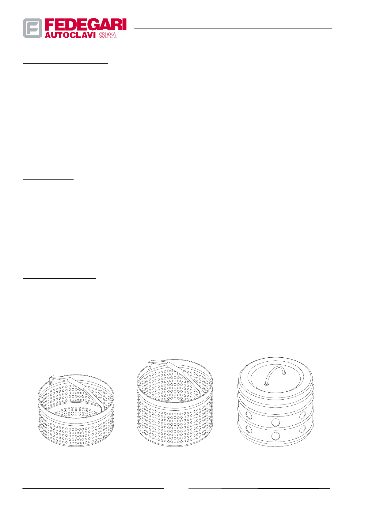
3.1.2.10. Loading/unloading devices
The machine loading/unloading system uses baskets in steel plate, fitted with folding handles (see Figure 3.4).
#68181 Rev.1
Figure 3.4-- Loading/unloading devices
-- 22 --
May 2001
Page 32

3.2. SAFETY SYSTEMS
3.2.1. Opening/closing system
Initial system state
Before closing the chamber, until the cover has reached the recommended position, limit switch Z001,checkingthe
system correct operation, is kept pressed by a spring, and breaks the circuit for compressed air supply to the seal
housing, thus preventing pressurized fluids from entering the chamber.
Starting closing operations
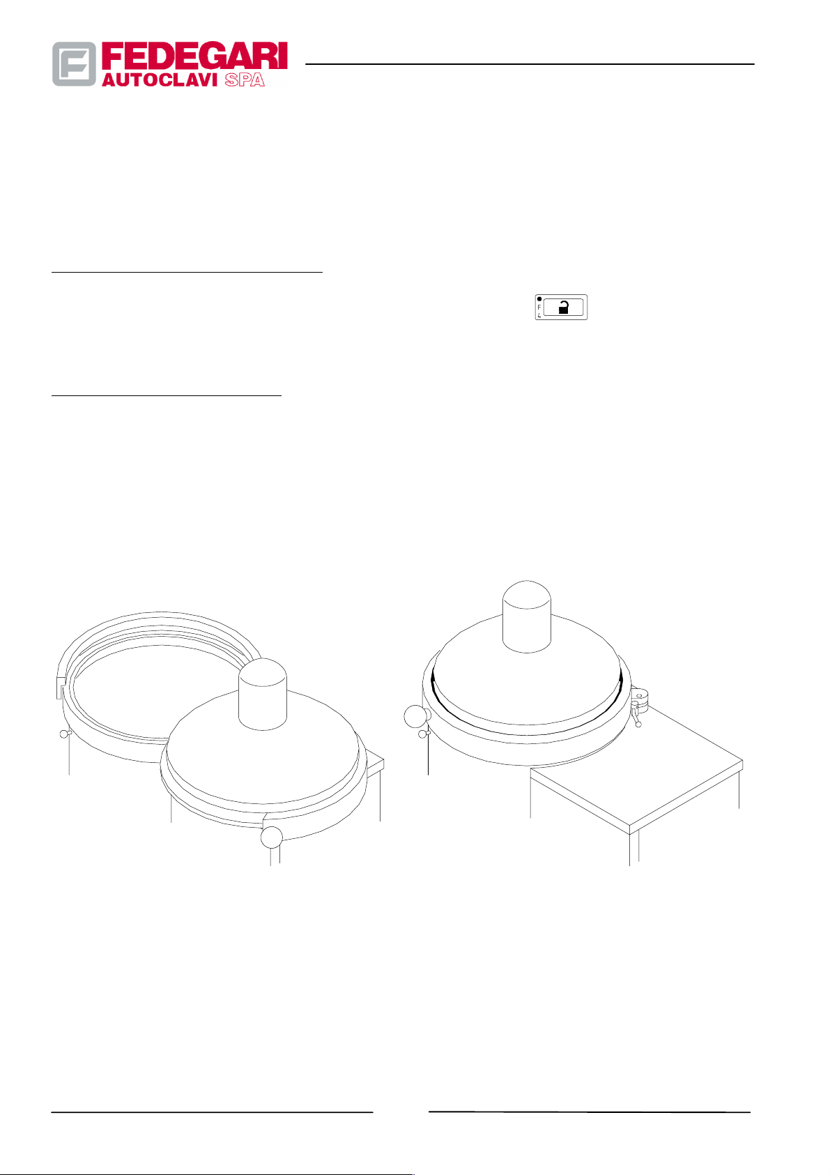
For safety reasons, both hands are required to manually turn the sterilizer cover from position A to position B (see
Figure 3.5).
When the cover has reached the position required for closing, limit switch Z001 changes its state and activates the
control for compressed air supply to the seal housing.
Closing the chamber
When the limit switch has selected the cover correct position, the operator must press the closing push--button
in order to let compressed air in the seal housing. The chamber starts closing and the cover is blocked.
Sealing system operation
The compressed air pushes the seal upwards and presses it against the cover perimeter, which is lifted from its rest
position held by two semicircular brackets.
The seal is pressed against the cover for perfectly closing the sterilizer, thus assuring tightness against pressurized
fluids entering the chamber.
Letting fluids into the chamber
Air pressure in the chamber is detected by pressure switch P002. When pressure has reached the set value, the
pressure switch warns that the chamber is closed and perfectly tight, thus enabling the process cycle and letting fluids
into the chamber.
Starting opening operations
The sterilizer can be opened only when:
-- the process cycle is completed;
-- pressure transducer P001 connected to the sterilizer control system and electro--mechanical safety pressure
-- 23 --
May 2001
#68181 Rev.1
Page 33
switch P005 indicate that the chamber internal pressure and atmospheric pressure have the same value again;
-- the chamber temperature measured by theat probe T001 is lower than the set value, so that the temperature of the
liquids to be sterilized in glass containers inside the sterilizer is less than their boiling temperature at atmospheric
pressure.
Exhausting air from the seal housing
After the above mentioned steps, the operator presses the opening push--button to exhaust compressed air
from the seal housing.
Opening the sterilizer manually
After automatic air exhausting from the seal housing, the sterilizer can be manually opened.
LEGEND
1. POS. A: Open chamber
2. POS. B: Cover in closing position
Figure 3.5 -- Chamber closure
POS. BPOS. A
#68181 Rev.1
-- 24 --
May 2001
Page 34
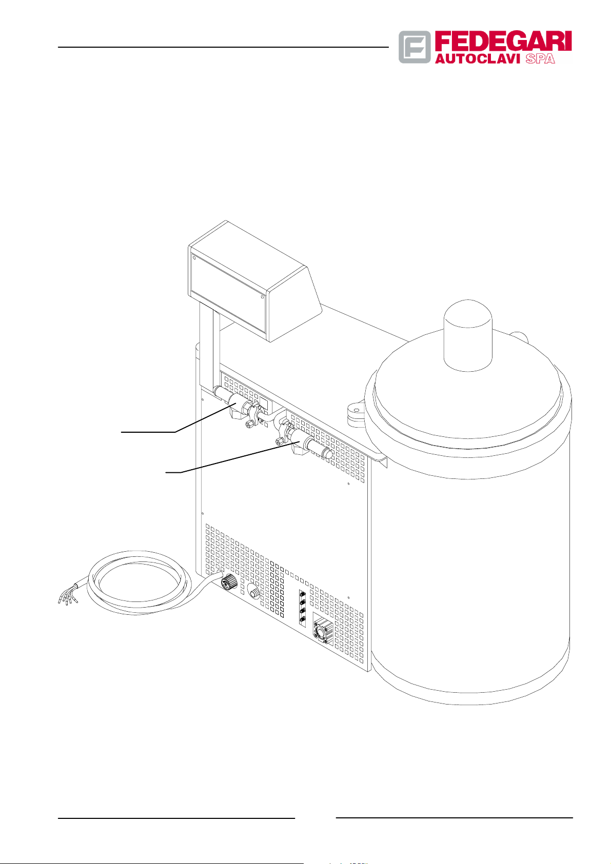
3.2.2. Safety valves
For the operator protection, the sterilizer features the following devices:
-- a safety valve to let out excessive chamber pressure;
-- a safety valve to let out admitted excessive pressure (working pressure value).
The valve is mechanically regulated on the maximum allowed value (design pressure value).
Steam generator
safety valve
Chamber safety valve
May 2001
Figure 3.6 -- Safety valve disposition
-- 25 --
#68181 Rev.1
Page 35
3.3. DATA SHEET
3.3.1. Main dimensions and weights
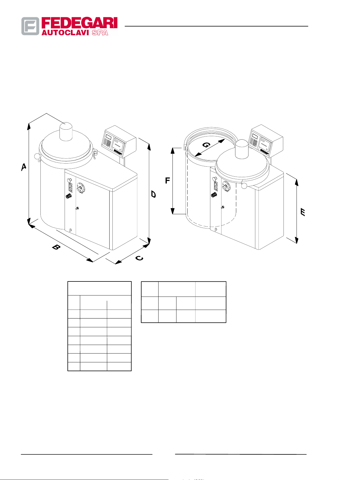
The main dimensions of the vertical steam sterilizer (models FVA2 and FVA3) are shown in the figure below: (see
Figure 3.7).
DIMENSIONS (mm)
FVA2
FVA--HT
A
1140 1140
B
996 1135
C
500 570
D
1220 1220
E
795 795
F
600 700
G
400 500
WEIGHT (kg)
(*) (**)
FVA3
Figure 3.7-- Main dimensions and weights
FVA2
FVA3
* With all the options
** With all the options and chamber full of water
173
188
under hydrostatic testing conditions.
248
328
CAPACITY
(l)
75
140
#68181 Rev.1
-- 26 --
May 2001
Page 36
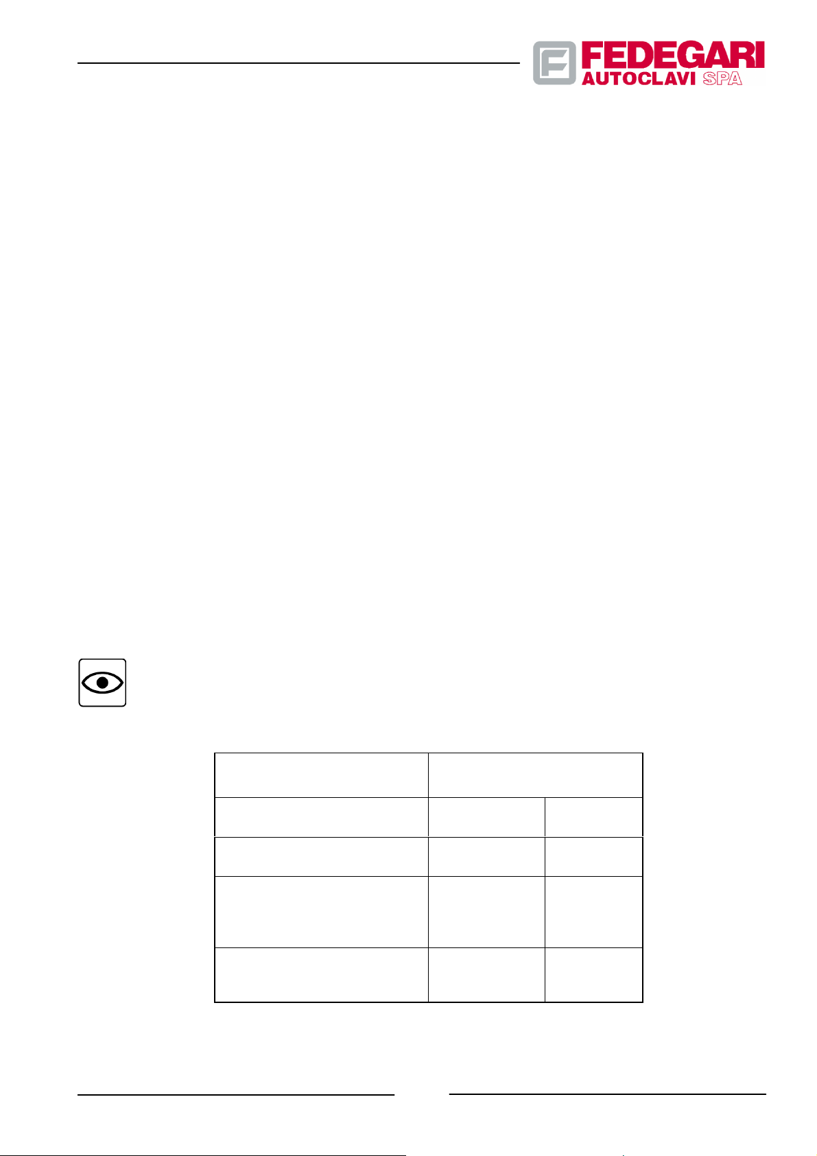
3.3.2. Operational data and main performance
DATA SHEET:
Installation class
Pollution degree 2
Sterilization process saturated steam
Process control automatic, through PLC
Operator interface keyboard and 4--line x 20-- character displays
Pressure measurement piezoelectric transducer
Temperature measurement heat probe Pt100
Chamber closing horizontally rotating cover with pneumatic seal
Sound pressure level < 64 dBA
(EN ISO 11202)
Max. operating pressure 3.5 bar abs.
Working pressure (Model FVA--HT) 6.2 abs. bar
Working temperature 139_C
Working temperature (Model FVA--HT) 155_C
Voltage 400V triphase + N + PE (standard version)
Frequency 50 Hz
Protection of drive components IP54
Installed power:
-- without steam generator 1.5 kW
-- with steam generator 10.5 kW
Absorption:
-- without steam generator 3A
-- with steam generator 18A
Materials:
-- chamber AISI 316Ti
-- valves and piping AISI 316L
II
NOTE
In compliance with the requirements of standard EN61010--par. 5.1.3.(C), the power load value
indicated on the CE plate refers to the most complete steriliser model, equipped with all optional
accessories.
USERS
Steam
-- max delivery (kg/h)
D.I water for generator
-- max delivery (l/h)
Network water (Max. 20_F)
-- for drain cooling (l/h) ◐
-- for vacuum pump (l/h)
-- for forced cooling (l/h)
Compressed air:
-- for actuators (Nl/min)
-- for back--pressure (Nl/min)
◐ : this value may change depending on the cycle configuration and on the type of the load.
FVA2 / FVA--HT FVA3
MODEL
12 12
15 20
20
200
50
10
210
200
240
20
50
10
May 2001
-- 27 --
#68181 Rev.1
Page 37

3.4. RECOMMENDED USE
CAUTION!
Do not use the sterilizer and its fittings to perform jobs othe r than those permitted and specified in
this manual.
This sterilizer can process both solid and liquid materials, according to the selected configuration, using different
sterilization processes.
The machine configuration allows to process:
-- Empty glassworks;
-- Stainless steel tools;
-- Parts of machines;
-- Small stainless steel reservoirs;
-- Different products, manufactured using materials suitable for this type of processing;
-- Liquid and semiliquid culture media (agar) in unsealed reservoirs;
-- Several solutions in unsealed reservoirs.
Sterilizers featuring vacuum pumps can process not only the above mentioned materials, but also:
-- Porous substances;
-- Various packed instruments;
-- Solids to be extracted dry;
-- Empty containers fitted with filters;
-- Fi lt er s.
3.5. FORBIDDEN USE
All applications excluded from the previous section are forbidden. Do not use a sterilization program fit for a specific
material for processing another type of material. Wet heat processing must be avoided in case of:
-- Flammable or explosive substances;
-- Non--flammable liquids, with high vapor pressure (halogenated hydrocarbons and similar substances), also in
closed containers;
-- Bottled/spray cylinder gas (also empty);
-- Substances which, when decomposing due to wet heat could generate noxious, flammable, explosive gases or
vapors as well as hazardous and flammable residues and solids.
As sterilization is assured by direct or indirect steam contact with the surfaces to be processed, wet heat sterilization
processes are not fit for:
-- Closed containers, steam--tight, to be sterilized inside (e.g. closed empty vials);
-- Closed containers, steam--tight, containing an anhydrous material to be sterilized (e.g. vials containing oily
anhydrous solutions and anhydrous powders).
If in doubt, do not hesitate to contact FEDEGARI.
-- 28 --
#68181 Rev.1
May 2001
Page 38

4. TRANSPORT, HANDLING, STORAGE
4.1. GENERAL WARNINGS
CAUTION!
Always disconnect the machine from its power supply before moving it.
Do not move the machine unless it is perfectly stable.
4.2. TRANSPORT
4.2.1. General information
To transport the machines described in this manual, always comply with the following rules.
4.2.2. Transport instructions
4.2.2.1. Packaging
To transport the machine, use the packaging system adopted for its delivery, provided the same carrier is used. In this
case, keep the original packaging or replace it if it is no longer available or in poor condition.
The packaging system includes a board to fasten the machine.
Two types of packaging are available, to meet all requirements:
-- Paperboard protection box;
-- Wooden box.
4.2.3. Specific procedures
4.2.3.1. Warnings
CAUTION!
The machine must not be turned over or inclined during lifting operations.
CAUTION!
Before starting lifting operations, make sure that the means used capacity is sufficient, compared
with the required carrying capacity and radii.
May 2001
-- 29 --
#68181 Rev.1
Page 39

4.2.3.2. Lifting the machine packaging
The machine packaging must be lifted in order to load/unload the carriers charged with the sterilizer transportation.
These operations require suitable lifting equipment, fitted with forks to handle the board.
CAUTION !
During lifting operations, access to the surrounding area is strictly forbidden.
CAUTION!
Use only suitable and certified lifting means. In Europe, they should feature the EC marking.
Loading
1. L ift the mac hi ne p ac kag ing w it h s uit abl e equi pm ent. C hec k t h at i t is pe rf ect ly b ala nce d d ur ing t hes e o per at ion s
and be careful to place it on the horizontal plane of the vehicle used for transportation, without dangerous tilting
and shaking.
2. F a ste n the boar d t o t he veh ic le p lat f or m b y m eans o f su ita ble r ope s, a nd pr ote ct i t , a s i t c oul d be da mag ed wh en
touching such ropes, or using other suitable means.
Unloading
-- With a machine fitted with suitable forks, lift the sterilizer packaging. Make sure that it is always balanced during
this operation and be careful to place it on a horizontal plane of the unloading area, without dangerous tilting and
shaking.
4.2.3.3. Handling on the installation site
Due to its small size, the sterilizer can be transported using a manual lift truck, inside the installation building, in order
to reach the chosen position.
The machine is generally positioned by two operators.
Follow this procedure:
1. Unpack the machine by taking it away from the board forming the packaging base. Keep the packaging, which
could be used for other transport operations;
2. Transport the machine, which is still forming part of the packaging, to the installation place, and place it on the
room floor;
3. Remove the fastening devices;
4. Lift the machine, and remove pallets.
#68181 Rev.1
-- 30 --
May 2001
Page 40

CAUTION!
Before transporting the machine to the installation site using lifts, check their carrying capacity, by
taking into account the following weights:
-- Machine weight (see the data sheet, section 3.3.1.);
-- Board weight (max. 20 kg);
-- Truck weight;
-- Operator’s weight.
CAUTION !
As regards handling, when the machine must be lifted, check that all ropes and lifting equipment
comply with the required capacity and, in Europe, with EEC regulations.
4.3. STORAGE
Before its final installation the machine can be stored, for a short time, in a closed an dry place, at a temperature
ranging from 4°Cto50°C , relative humidity lower than 80%.
If no suitable rooms are available please ask FEDEGARI to deliver the machine equipped with welded mixed case for
boxesbysea.
WARNING
The sun’s rays are likely to damage the plastic and rubber components of the sterilizer. Avoid prolonged exposure to direct sunlight.
4.3.1. Short shut--downs
No problems are involved for shut--downs of up to two months.
4.3.2. Prolonged shut downs
In case of shut- -downs of more than two months, apply silicone oil on seals to prevent gluing and quick wear. After
prolonged shut--downs, check whether seals must be replaced.
May 2001
-- 31 --
#68181 Rev.1
Page 41

5. INSTALLATION AND DISMISSION
5.1. ENVIRONMENTAL CONDITIONS FOR USE
The installation site must be well lighted and aerated. The machine and its control system require the following
environmental conditions:
-- Room temperature: 10_ ¸ 40_C;
-- Max. relative humidity: 85% con T £ 40_C;
CAUTION!
If the installation site is artificially lighted, check the related devices for compliance with the
characteristics required by the law in force in the country where the machine has been installed, as to
operators’ safety and health. The machine features a LCD display.
Align and position the display so as to avoid reflections and reverberations on the operator’s visual
plane.
5.2. SPACE REQUIRED FOR USE AND MAINTENANCE
The available space surrounding the machine must allow the operator to perform :
-- the necessary movements to use the control devices without difficulty;
-- the necessary movements for loading/unloading operations with the accessories supplied;
-- the ordinary maintenance, such as cleaning and processing operations;
-- the extraordinary maintenance operations.
5.3. PACKING REMOVAL
Special containers (packaging) are used to transport the machine, wrapped in materials assuring protection against
bad weather during transportation and short- -term storage.
All packaging materials must be carefully removed, without damaging the machine structure and surface.
The sterilizer external cabinet is painted. Keep it with care, to avoid scuffing its surface.
NOTE
When using the machine in another site, keep the original packaging container.
#68181 Rev.1
-- 32 --
May 2001
Page 42

5.4. POSITIONING THE MACHINE
CAUTION!
When installing the sterilizer, carefully follow the instructions of the installation drawing, as well as
this manual’s instructions.
Do not forget that:
* the installation room floor must comply with the required capacity, including the additional
weight resting on its structure, due to scheduled hydraulic tests.
* the connections to the floor must bear a 80°C temperature at least.
* all technical safety measures recommended for seismic areas must be adopted in conformity
with the related regulations.
* All pipes and accessories used for draining the sterilizer service fluids, the lines and fittings for
connecting to the control panel and to other sterilizer components must comply with the
regulations of the applicable law.
NOTE
The hydraulic test required by the regulations of the country where the machine is used, t o be
performed when the sterilizer has been installed with its user, might increase t he load and reduce the
stability of the sterilizer supporting structure. The installation scheme indicates the machine weight
and size.
CAUTION!
When installing the machine DO NOT create structural links with surfaces or elements subject to
stress or dynamic load outside the sterilizer. Should such links exist in the installation area, please
let FEDEGARI know the related problems be f ore buying the machine.
1. Position the machine, so that it rests on a perfectly flat surface;
2. The sterilizer must be placed on a flat surface, near a fume hood;
3. Place the machine according to the instructions given in FEDEGARI’s drawings and installation documents (see
Section 1.1.1., allied publications).
May 2001
-- 33 --
#68181 Rev.1
Page 43

5.5. CONNECTIONS TO POWER SOURCES AND SERVICE NETWORKS
5.5.1. Hydraulic connections of the users
1. The hydraulic connection to the users is made by means of flexible hoses (see Figure 1.1).
This system also requires:
* hose adapters (ø16 mm) for the purge system;
* quick- -connection ø 6 mm for network water;
* quick--connection ø 4 mm adapters for other users (demineralized water, steam and compressed air).
CAUTION!
It is recommended to connect the sterilizer pur ge system to the drains, taking into account
ventilation requirements. Network backflows can result from non--compliance w ith these
instructions and the sterilization chamber might be contaminated/polluted.
A simple check valve is not considered to be an effective microbiological barrier according to
international standards CGMP/CGLP.
To prevent dangers of pollution to the water supply network, it is recommended that suitable
back--flow prevention devices and barriers be installed on the intake line of the vacuum pump.
To carry out the connections to the users and the trap, all pipes must be kept at atmospheric
pressure.
Make sure that all fittings feature their specific tag.
WARNING!
The deionized wate r, required with option K10 Steam Generator, must have precise conductivity
characteristics.
Conductivity can change according to the type of plant by which it is obtained and the maintenance
conditions of the plant. With modern plants you can obtain water with a conductivity lower than 5
mmmmS/m, an optimum value for this application.
Water with a conduc tivity above 5 mmmmS/m can be used, though, of course, maintenance jobs on the
generator will be more frequent. We recommend that you avoid using water having a conductivity
above 30 mmmmS/m.
Finally, the following information can be summed up:
Recommended conductivity: 2 to 15mmmmS/m, inspecting the generator every year.
Admitted conductivity: up to 30 mmmmS/m, inspecting the generator every six months.
CAUTION!
The machine is equipped with safety valves calibrated and checked by FEDEGARI AUTOCLAVI at its
factory, at an ambient pressure of 1 bar.
If the machine is installed in a place where the ambient pressure is notably different from 1 bar áááá±±±± 0.1
bar), FEDEGARI recommends y ou to have the valves re--calibrated by qualified personnel and/or by
the engineers selected for installing the machine, according to the new ambient pressure and before
starting the work cycle. This trick ensures safety and proper conditions of use.
#68181 Rev.1
-- 34 --
May 2001
Page 44
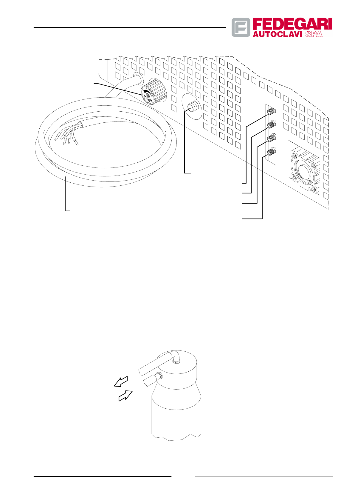
Steam generator
manual purge valve
Feeding cable
Main drain
Network water 2.54.5 bar
Deionized water 14bar
Compressed air 4.5 bar
(For model FVA--HT 6 bar)
Saturated steam
Figure 5.1 -- User connections
(optional) 4.5 bar
5.5.1.1. DEIONIZER options (T30)
If the deionizer has been installed (option T30), connect it as follows (cf. Figure 5.2 ):
1. Connect pipe A to the water to be deionized (Ideal pressure: 0.3 bar -- 0.8 bar max.; if the water pressure at the inlet
is higher, install a pressure reducer with pressure gauge on the network, upstream of the deionizer.
2. Connect pipe B to the deionized water load, on the sterilizer.
3. Open the newtork water cock slowly.
4. The resin in the cartridge becomes progressively blue, from top to bottom.
When the blu resin reaches an height of approx. 15 cm from bottom, this will indicate that the cartridge is empty
and must be replaced with a new one.
B
Deionized water
Water
A
May 2001
Figure 5.2 -- Deionizer connection
-- 35 --
#68181 Rev.1
Page 45
WARNING!
The deionizer’s reservoir is designed for a max. pressure of 2 bar. Any higher pressure would
cause the reservoir collapse, resulting in uncontrolled water spillage.
5.5.2. Wiring
WARNING!
The sterilizer is delivered with a five--pole feeder cable , featuring a suitable section, without plug and
cable terminal.
The customer must complete all machine connections to power supply. These connections must
take into account the power required by the machine (see section 3.3.2. as well as the user plant
conditions), so that their are fully compatible, in c ompliance with safety rules.
WARNING!
The connection of the sterilizer to the elect rical network requires t he installation of a protection
system on the supply electrical pa n el. To ensure safety, the installator should use a magnetothermal
switch of a suitable size, based on the equipment’s electrical absorption (cf. see paragraph 3.3.2.).
WARNING!
The equipment has a single serial output for connection to any external equipment. This output is
characterised by a net separation through the double insulation of the power and control circuits.
Make sure that the equipment connected to this output is characterised by an equivalent insulation
class.
When carrying out such connections, always take into account the conductor colors inside the cables, according to
IEC standards:
-- BLACK : phases (R, S,T);
-- BLUE : neutral (N);
-- YELLOW/GREEN : earth .
Therefore:
1. IF A VACUUM PUMP IS NOT AVAILABLE: the connection has been completed.
2. IF A VACUUM PUMP IS AVAILABLE: slowly turn the pump and check its direction of rotation to make sure that the
phase sequence is correct. If the pump is rotating in the wrong direction, invert the two phase conductors, as the
only three--phase motor (requiring a correct sequence) has been installed on the vacuum pump.
#68181 Rev.1
-- 36 --
May 2001
Page 46

5.6. INSTALLATION MONITORING
WARNING!
In conformity with the laws current in the Country of de stination, pressure equipment must be
checked on the responsibility of the User by a competent inspection body.
Before using the machine, carry out a short running--in, consisting of at least two complete no--load cycles. During this
period, check the sterilizer for any failures. The machine can start its usual production cycles only on test completion, if
no problems have occurred. In case of failures, do not hesitate to contact the manufacturer.
5.7. DISMISSION
To dismiss the machine, follow the procedures listed above, but in reverse.
WARNING!
The eventual demolition of the machine must be carried out according to the laws current in the
Country of destination.
May 2001
-- 37 --
#68181 Rev.1
Page 47

6. USING THE STERILIZER
6.1. OPERATION DESCRIPTION
6.1.1. General information
The most important operations dealing with materials to be processed and sterilized, are defined ”sterilization
process”, or ”sterilization cycle” or ”cycle”. These operations also concern the presetting/preparation of the sterilizer
sub--systems and components, as well as the batch and materials to be processed.
The sterilization process consists of the following main steps:
-- Sterilizer preparation;
-- Product sterilization;
-- Product cooling or drying;
-- Final phase.
Each operation also includes other operating processes, the ”phases”, which might change, based on the programs
selected by the operator through the menu, their sequence and size, with different physical parameters of processed
liquids/fluids.
The machine operation (i.e. the sequence of operations performed on fluids/liquids and on power requirements
during the process) is examined below, starting from the most important activities required to process the batch.
The following explanations also describe the physical/functional blocks controlling the above mentioned operations.
The most important activities and the related operations are the following:
-- Sterilizer preparation
including:
* Starting the machine;
* Loading the product and starting the cycle;
-- Batch sterilization
including:
* Chamber pre--heating;
* Initial air exhausting;
* Chamber heating;
* Sterilization using saturated steam;
-- Cooling or drying
including:
* Spontaneous cooling;
#68181 Rev.1
-- 38 --
May 2001
Page 48

* Convection cooling, with forced air circulation using a fan;
* Drying, using a vacuum pump;
-- Final phase
including:
* Atmospheric pressure reset;
* Cycle completion;
The machine operation during the above mentioned steps will be also described.
6.2. CONTROLS
6.2.1. General information
The sterilizer is controlled through a system consisting of a dedicated microprocessor card. The microprocessor
manages the main drives, monitors and controls the machine hardware and enables the operating sequences
(phases) of the specific sterilization ”cycle” programmed.
The microprocessor, hereinafter the ”process controller”, also controls the operator dialogue, through proper
peripherals.
The machine is fitted with control elements which, independently of the microprocessor,integrates its tasks for several
control functions.
6.2.2. Con trol desks
The sterilizer features functional control elements and units located partly on the front cabinet paneling and partly on
the Operator Panel.
The machine is equipped with the following control devices (see Figure 6.1):
-- LCD display (pos. 1);
-- Keyboard (pos. 2);
-- Main switch (pos. 7);
-- Printer (optional K81) or Datalogger (optional K82) (pos .3);
-- Emergency push--button (pos. 4);
-- Control pressure--vacuum gauge (pos. 5);
-- Manual purge valve (not available for model FV A--HT) (pos. 6).
-- 39 --
May 2001
#68181 Rev.1
Page 49
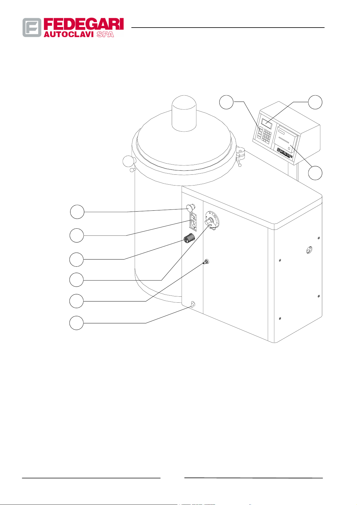
The operator can stand in front of the panel lodging the control elements in order to work without problems and to
immediately identify warnings and messages.
LEGEND
1. LCD Display
2. Keyboard
3. Printer or Datalogger
4. Emergency button
5. Pressure-vacuum gauges
6. Manual pressure relief valve
of the chamber
7. Main switch
8. Technical cabinet key
9. Effluent duct
4
5
6
12
3
7
8
9
Figure 6.1 -- Position of the control elements
6.2.3. Display
It is the most important display device (see Figure 6.2) used by the operator. It is a monochrome, LCD model,
consisting of 4 lines x 20 columns.
It displays all menus which can be selected by the operator as well as the most important commands given to the
machine. In particular, it displays both pressure and temperature parameters of the sterilization cycle in progress.
The parameters related to the sterilization cycle in progress and all warnings are also displayed.
#68181 Rev.1
-- 40 --
May 2001
Page 50
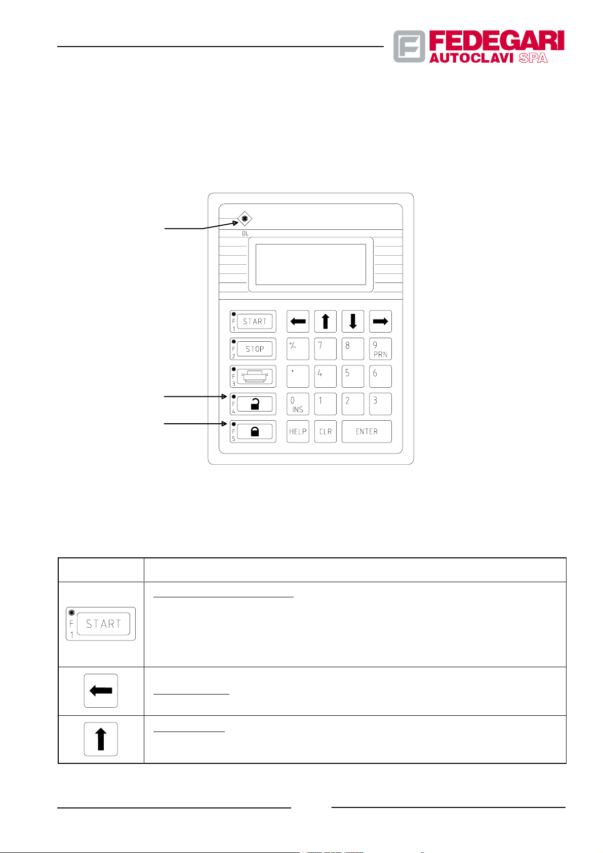
6.2.4. Keyboard
The keyboard (see Figure 6.2) is directly managed by the process controller. It is the most important equipment used
by the operator to dialog with the machine and to give it the operating commands required.
It is a diaphragm keyboard, featuring 24 keys and 5 LED indicators. Press the keys to control the process, while
interacting with the controller to carry out operations.
LED1
LED2
SIMB./Nr.POS.
LED3
Figure 6.2 — Display/keyboard unit
Table 6.1 -- Keyboard: controls
DEVICE/FUNCTION
F1 -- Key ”Start/Step--by--Step”: it is a double function key.
1)It allows to start the program selected during the preparation phase;
2)During the sterilization program execution, press it in order to enter the next operating phase,
while blocking the controls related to the operating phase in progress without waiting to reach
the preset end--of--phase value.
Key ”Left Arrow”: allows to scroll in reverse the pages of the process software menus.
May 2001
Key ”Up Arrow”: It is a double function key. It allows to scroll upwards the selected page, if it
has more than 4 lines. Press it after pushing key ”INS” to move the cursor on the parameter
numeric fields.
-- 41 --
#68181 Rev.1
Page 51
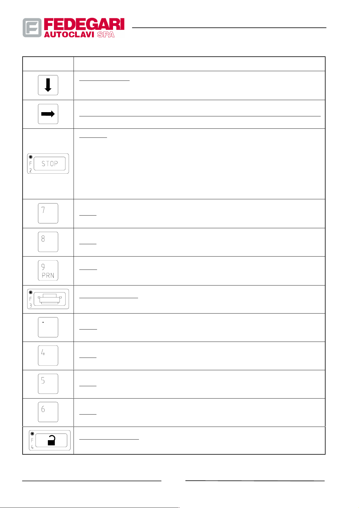
SIMB. / Nr. POS. DEVICE/FUNCTION
Key ”Down Arrow” : it is a double function key. It allows to scroll downwards the selected page,
if it has more than 4 lines. Press it after pushing key ”INS” to move the cursor on the parameter
numeric fields.
Key ”Right Arrow”: allows the sequential scrolling of the pages of the process software menus.
F2 -- St op: this key has three functions.
1) It allows to return to the main menu from the selected program preparation phase.
2) During the program execution, press it to enter the emergency phase immediately. In the
Emergency phase, but not in Decontamination Emergency, pressing the ”STOP” keys
again allows you to terminate the program, entering the ”Pressure Balancing” and ”Cycle
End” phases.
3) During the end--of--cycle phase, press this key to conclude it and to deactivate the acoustic
signal.
Key 7: allows to enter number ”7” in the selected field.
Key 8: allows to enter number ”8” in the selected field.
Key 9: allows to enter number ”9” in the selected field and to print through the function identical to key F3.
F3 --Key ”Print image”: allows to print the displayed image, when the printer is configured and
without processes in progress.
Key ° : allows to enter the decimal point in the number keyed in.
Key 4: allows to enter number ”4” in the selected field.
Key 5: allows to enter number ”5” in the selected field.
Key 6: allows to enter number ”6” in the selected field.
#68181 Rev.1
F4 --Key ”Open cover”:press it only when no sterilization processes are in progress. It controls
the cover safety devices and compressed air exhaust from the cover seal.
-- 42 --
May 2001
Page 52
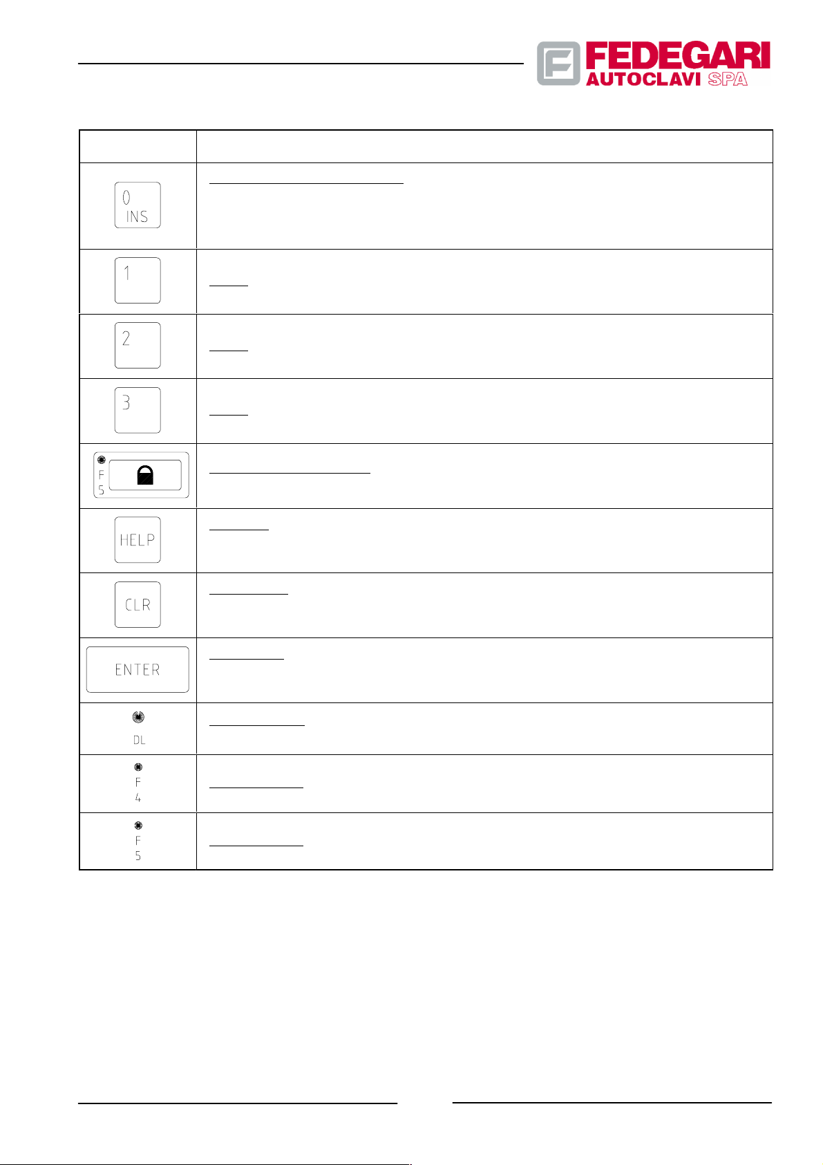
SIMB. / Nr. POS. DEVICE/FUNCTION
0/Ins it is a double function key:
1) It allows to have access to the insertion mode (INS) and makes the numeric field of the
selected parameter blink.
2) In the insertion mode, it allows to enter number 0 in the selected field .
Key 1: allows to enter number ”1” in the selected field.
Key 2: allows to enter number ”2” in the selected field.
Key 3: allows to enter number ”3” in the selected field.
F5 -- Key ”Cover closing”: it is activated when no sterilization processes are in progress.
Through the microswitch ”cover closing” it allows to supply compressed air to the cover seal.
Key Help: it provides useful information on the displayed page. If its message consists of more
than4lines,keeptheHelp key pressed and use keys ”Up Arrow” and ”Down Arrow” to display
the whole text. To return to the previous page, release the Help key.
Key ”Clear”:it is a double function key. When displaying and selecting the sterilization process parameters, it allows to return to the previous page. During the execution of the sterilization program, press it to erase temporarily the message displayed in case of alarm.
Key ”Enter”: it is a double function key, allowing to confirm the value of the modified parameter
through the numeric keys. During the sterilization cycle execution, it allows to disable the
alarm buzzer.
LED indicator 1: If it is OFF,no keys have been pressed. If it is blinking, a communication error
has occurred ; if it is ON, a key has been pressed.
LED indicator 2: If it is ON, the cover is opened (the seal is not pressurized).
LED indicator 3: If it is ON, the cover is closed (pressurized seal).
6.2.5. Main switch
The main switch, located on the rear of the operator panel, allows to enable the process controller. It also allows to
enable the related peripherals, which form, together with the controller, the main machine hardware. Switch it to the
<O> position to disable the process controller and the peripherals connected to it.
-- 43 --
May 2001
#68181 Rev.1
Page 53
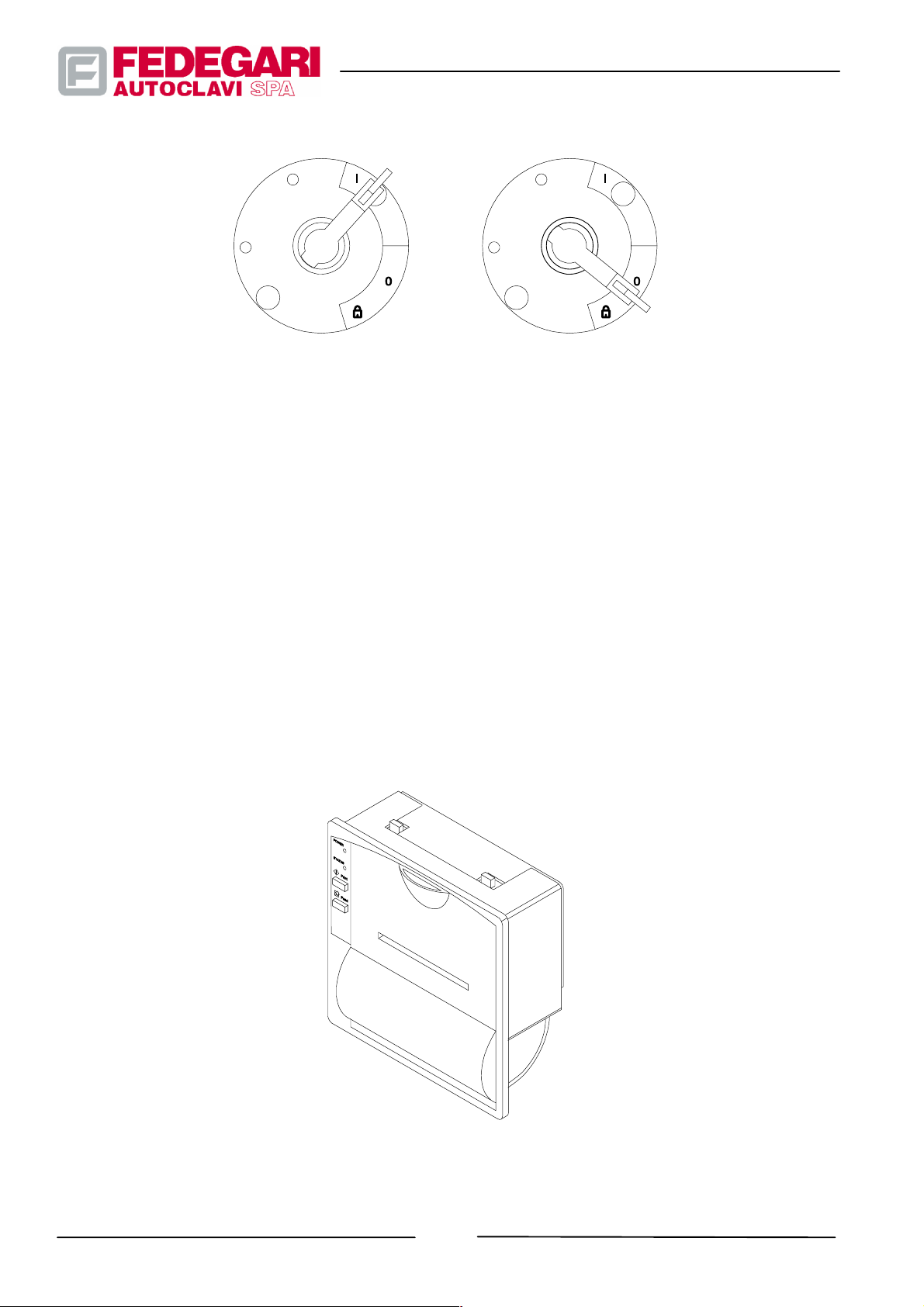
Switch activated
Figure 6.3 --Main switch
Switch deactivated
6.2.6. Printer (optional)
The machine is equipped with a printer (see Figure 6.4 ), featuring a 200 dpi thermal printing device, RS232 interface.
It can support the following transmission protocols:
The printer is directly connected to the process controller and must document in real time the development of the
sterilization program in progress.
It is also used to obtain parameter reports and data on the sterilization cycle completed. The operator must feed it with
new paper and remove the reports printed on the sterilization process completion.
#68181 Rev.1
Figure 6.4 -- Thermal printer
-- 44 --
May 2001
Page 54
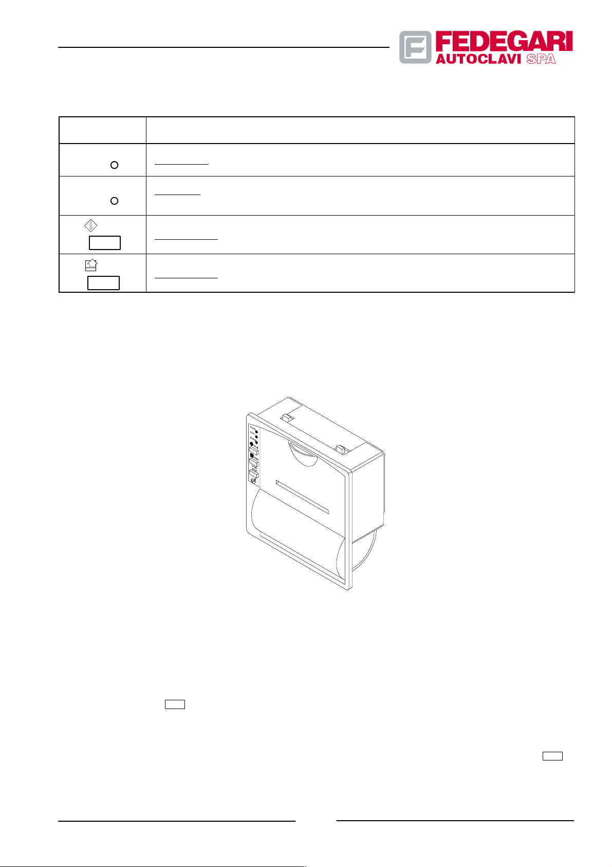
Table 6.2 -- Thermal printing: commands and controls
SYMBOL /POS.
No.
POWER
STATUS
Green Led: if lit, the printed ir supplied.
Red Led: if continuously lit, indicates the presence of an error (excessive/insufficient head
DEVICE/FUNCTION
supply or excessive head temperature), if blinking, there is no more paper.
Print
Push--button: not enabled.
Feed
Push--button: is press, the paper is fed.
6.2.7. Datalogger -- Kit EN285 (optional K82)
The DATALOGGER (cf. Figure 6.5) is provided with a 200 dpi thermal printing device, RS232 interface.
Figure 6.5 -- Datalogger
For Printing, it considers the external data, entered through the serial port, and detects temperature and pressure
signals with double--detection heat probe Pt100 and a pressure transducer (provided in the Kit).
The Recording can be controlled either manually or automatically:
START
STOP
-- Manually with key
;
-- Automatically with an external digital signal corresponding to ”CYCLE IN PROGRESS”.
START
The two operating modes can be selected in the set--up menu; if automatic operation is selected, the key
STOP
disabled.
-- 45 --
May 2001
#68181 Rev.1
is
Page 55
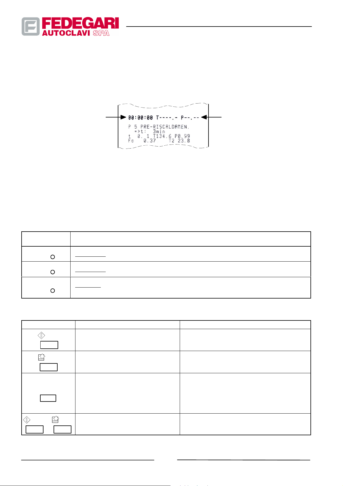
The Recording frequency is set, in the set--up, as rate time (”synchronous” recording).
When the recording starts (and, then, according to the rate), the following data is printed (cf. Figure 6.6):
-- Recording time/duration (hh:mm:ss);
-- Temperature (T--------.--);
-- Pressure (P----.----).
Figure 6.6 -- Printing of ”Start recording” data
Among ”synchronous” rates, some ”asynchronous” recordings may occur that, activated through an external signal
from the second digital input, are marked by an asterisk.
At the end of the recording (end of cycle), you can print a chart representing the temperature/pressure curves. The
curve can include up to 255 samplings. The temperature/pressure range that can be represented is 0 to 150_C and 0
to 5 bar.
Table 6.3 -- Datalogger: led functions
SYMBOL /POS.
No.
POWER
START
STATUS
KEY
Print
Feed
START
STOP
DEVICE/FUNCTION
Green Led: if lit, the Datalogger is supplied.
Green Led: if blinking, the recording is in progress.
Red Led: if continuously lit, indicates the presence of an error (excessive/insufficient head
supply or excessive head temperature), if blinking, there is no more paper.
Table 6.4 -- Datalogger: keys’ functions
ACTIVATED ON START--UP ACTIVATED DURING OPERATION
CALIBRATION MENU: sensor
calibration.
.
Print date/time (just press the key);Paper feed
Auto--test.
(press the key and hold it down);
.
Recording start, if enabled in
configuration and if sensors are
calibrated.If unset sensors are
detected, the Datalogger immediately
prints the part of the calibration menu
relating to the unset sensor.
If enabled in configuration:-- Start recording
(press the key once);-- Stop recording (press the
key twice).
.
Print Feed
+
#68181 Rev.1
SET--UP Menu
SET CLOCK CALENDAR Menu: date/time
setting.
-- 46 --
May 2001
Page 56
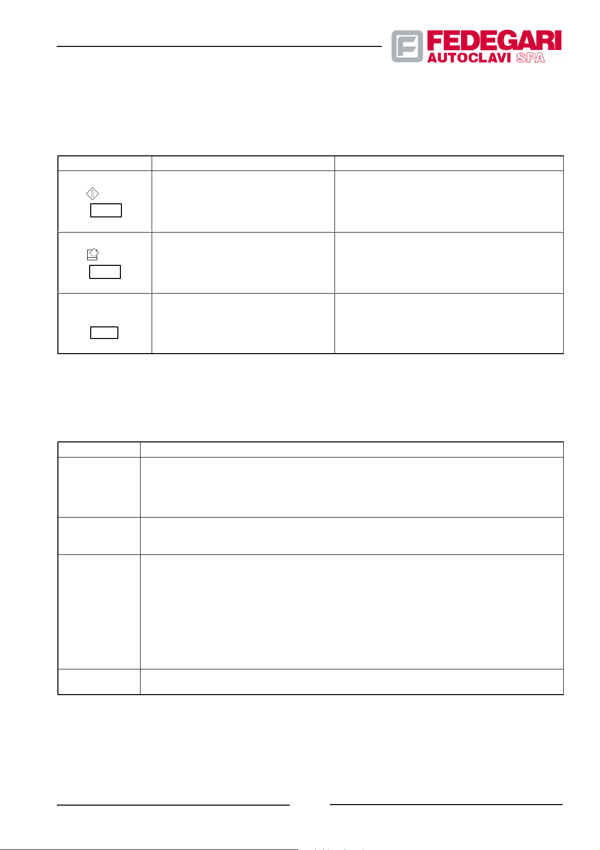
. In the CONFIGURATION menus the keys have a dedicated function described in the following table.
Table 6.5 -- Datalogger: keys’ function in the CONFIGURATION menus
KEY
Print
Feed
START
STOP
1. AUTOTEST
2. SET--UP
3. CALIBRATION MENU
4. SET CLOCK CALENDAR
1. AUTOTEST
2. SET--UP
3. CALIBRATION MENU
4. SET CLOCK CALENDAR
1. AUTOTEST
2. SET--UP
3. CALIBRATION MENU
4. SET CLOCK CALENDAR
MENU FUNCTION
1. CONTINUE
2. INCREMENT
3. CALIBRATION
4. INCREMENT
1. EXIT
2. CONFIRM
3. EXIT
4. CONFIRM
1. --
2. SKIP
3. --
4. EXIT
The TEST and CONFIGURATION menus, in English, are listed in the following table.
Table 6.6 -- Datalogger: TEST and CONFIGURATION menus
MENU
FUNCTION
Displays: -- the make, model and version of the device’s firmware;
-- the configuration parameters;
AUTOTEST
-- the set date/time;
-- the characters of the available fonts.
Performs: -- the DOT TEST.
Parameters: -- PRINT MODE
SET--UP
-- SERIAL MODE
-- REAL TIME CLOCK
For the initial setting/creation of the high and low points for analog inputs’ R/T (ohm/_C) and
I/P (ampere/bar) conversion characteristics. These are set by connecting analog inputs to
precision potentiometer in order to obtain the requested resistances and currents.N.B. The
recorder activates this manu automatically if the characteristics are lost, e.g. after the back--up
CALIBRATION
MENU
battery has run down.After calibration, the analog signals must be calibrated with the OFFSET
and GAIN functions in the SET--UP menu.The OFFSET can be set b y carrying--out the
calibration at a low point; the characteristics are thus increased or decreased by entering a
positive or negative value, within the range. Then, the GAIN can be set by carrying--out the
calibration at a high point; if the reading is too low, set a value above 1, if it is too high, set a value
below 1, within the range. The R/T and I/P characteristics can be adjutsed properly.
SET CLOCK
CALENDAR
To set the date and time operating through the Datalogger’s internal clock.
May 2001
-- 47 --
#68181 Rev.1
Page 57

Table 6.7 -- Datalogger: parameters of the SET--UP menu
PARAMETERS
FINAL GRAPH
OFFSET TEMP
OFFSET PRESS
GAIN TEMP
GAIN PRESS
START/STOP
TIMER
LANGUAGE
OPTIONS DESCRIPTION DEFAULT
ENABLED
DISABLED
--9. 9_C
+9.9_C
--0.99 bar
+0.99 bar
0.667
1.500
0.667
1.500
PRINT KEY
EXT. INPUT
Graph at the recording end. ENABLED
Translation of the R/T characteristic 0.0_C
Translation of the I/P characteristic 0.0 bar
Rotation of the R/T characteristic 1.0
Rotation of the I/P characteristic 1.0
Manual recording (activated with the START/STOP
key).Automatic recording (digital input).
EXT.
INPUT
10,20,30,40,50
SEC.
1,2,3,4,5,6,7,8,9,1
0,15,20,25,30,40,5
Printing rate during recording. 10 sec
0MIN.
1HOUR
Translation of the final graph heading in:
IT
EN
DE
FR
NL
-- Ita lia n
-- English
-- Ger ma n
-- Fre nch
-- Dut ch
IT
COLUMNS
PRINT
MODE
FONT
CR--LF
24--FONT 16x24
40--FONT 9x24
NORMAL
REVERSE
LITTLE
DOUBLE WIDTH
DOUBLE HEIGHT
EXPANDED
1
2
HONOR CR
IGNOR CR
Normal dimensions (24 columns).
Small (40 columns).
24
Legible after the tear or legible on the printer. NORMAL
-- normal
-- double width
-- double height
LITTLE
-- large characters
Type of characters 1
In printing mode the return (carriage return) is
honored or ignored.
HONOR
#68181 Rev.1
-- 48 --
May 2001
Page 58

PARAMETERS DEFAULTDESCRIPTIONOPTIONS
NORMAL
DENSITY
DARK
VERY DARK
VERY LIGHT
LIGHT
Black density:
-- nor mal
-- dar k
-- very dark
-- very light
-- ligh t
NORMAL
SECONDS
ENABLE
DISABLE
Enables the printing of seconds. ENABLE
May 2001
-- 49 --
#68181 Rev.1
Page 59
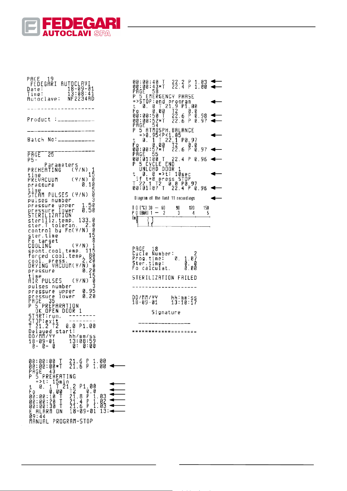
Figure 6.7 shows an example of the recording printing in a sterilization cycle.
fifth recording line
sixth recording line
phase start printing
seventh recording line
eight recording line
phase start printing
ninth recording line
tenth recording line
phase start printing
eleventh recording line
final graph printing
#68181 Rev.1
first recording line
printing of the first phase start
10 seconds rate
second recording line
third recording line
fourth recording line
alarm printing
Figure 6.7 -- Example of recording printing
-- 50 --
May 2001
Page 60

6.2.8. Emergency button
Press this button to stop the machine immediately (EMERGENCY STOP) and to switch on the master switch. Once
pressed, this button mut be reset manually by pulling it horizonally (see Fig. 6.8).
Connection Reset
Figure 6.8 -- Emergency push--button
6.2.9. Control pressure--vacuum gauges
The machine mechanical analog pressure pressure--vacuum gauges (see Figure 6.9) display pressures in the
sterilizer pressurized components.
One of these devices measures the sterilization chamber pressure.
The other one indicates the steam generator pressure, if it has been installed, or the steam supply line pressure.
These gauges feature a scale for reading pressure (bar).
They continue to detect pressure and vacuum even when the sterilizer is deactivated and the chamber is not
operating.
Chamber pressure-- vacuumgauge
Generator pressure-- vacuumgauge
May 2001
Figure 6.9 -- Control pressure--vacuum gauges
-- 51 --
#68181 Rev.1
Page 61
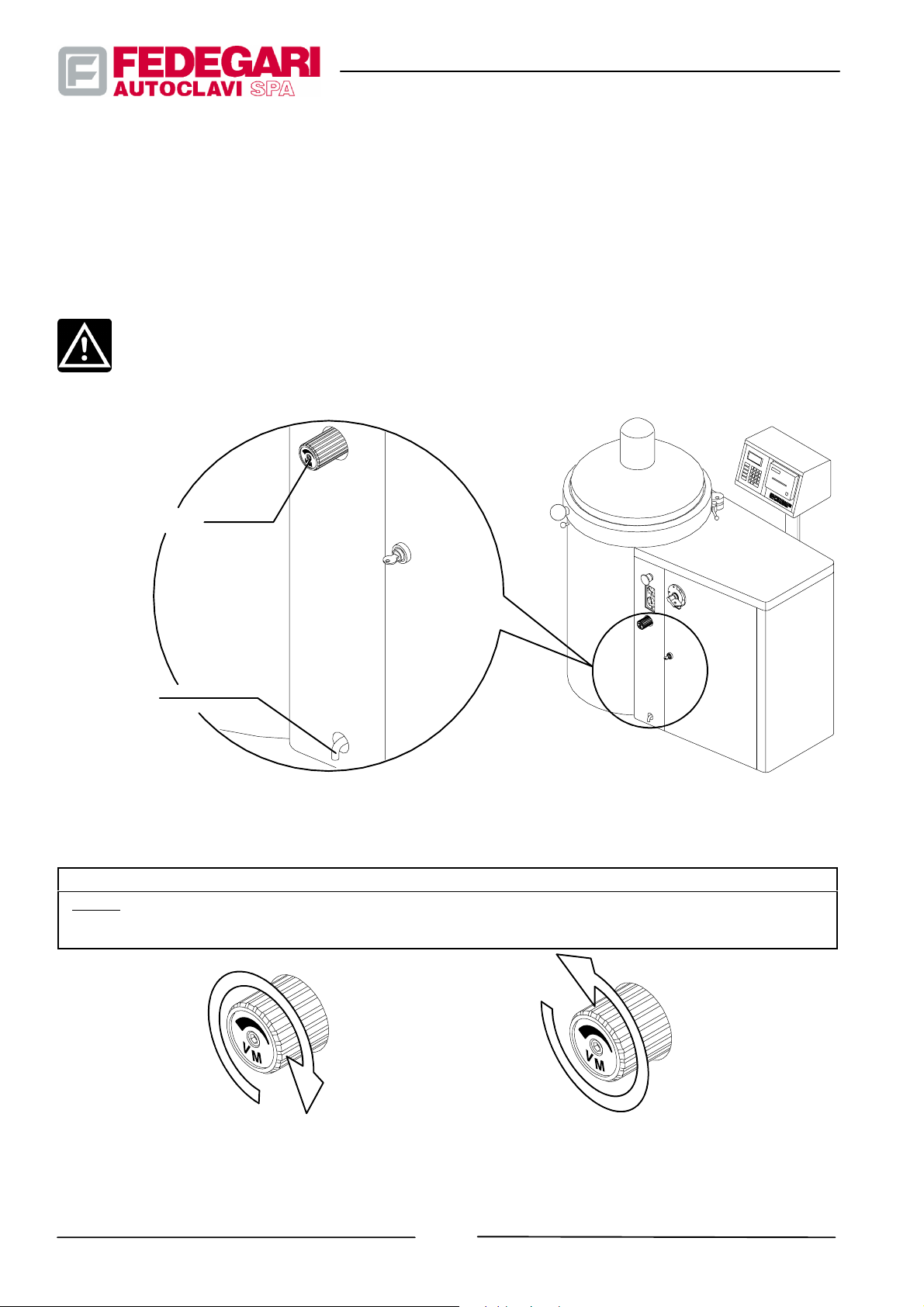
6.2.10. Manual pressure relief valve of the chamber (not available on FVA--HT model)
It is a diaphragm valve (Fig. 6.10) located on the front panel of the machine, near the vacuum--pressure gauges, and
connected to the sterilizer chamber. If the machine cannot run in automatic mode, the operator can use this valve for
manually checking whether any pressure is left in the chamber on the sterilization process completion. This valve is
also used to let out the pressure generated in the chamber when the cover must be opened for new loading
operations.
CAUTION !
Risk of scalding! Opening the manual valve may cause hot steam to be expelled from the release duct
located at the bottom of the front panel of the machine.
Manual drain valve
Effluent duct
Figure 6.10 -- Manual pressure relief valve of the chamber and effluent duct
Table 6.8 -- Manual purge valve (see Figure 6.11)
DEVICE/FUNCTION
Knob : Turn it clockwise until it stops, in order to intercept the pipe for purging the sterilization chamber.To purge
the chamber, turn the knob anticlockwise from the CLOSE position. To obtain maximum draining section turn the
knob anticlockwise until it stops.
a. Valve closing b. Valve opening: drainage
#68181 Rev.1
Figure 6.11 -- Manual purge valve: operations
-- 52 --
May 2001
Page 62

6.3. ACCESS LEVELS AND OPERATING MODES
6.3.1. Access levels
To protect the system and to guarantee a proper hierarchy, according to all identified tasks, access is allowed only for
different authorization levels, by typing in a code, also known as ”password”.
Access is allowed according to 5 levels (0 to 4).
Each level allows to access other levels, by typing in a specific password.
The first 2 (0 and 1) of the 5 access levels (3 and 2), defined ” FEDEGARI DEVELOPER” and ” FEDEGARI
PERSONNEL” respectively, are reserved to Fedegari’s engineers, the other levels (2, 3 and 4), defines ”User
supervisor”, ”User : user” and ”Stand--by” are reserved to the sterilizer personnel.
Table 1.9 below shows the operating functions associated to every level.
Table 6.9 -- Access levels to operating functions
ACCESS LEVELS
4 STAND--BY
This password sets the system in a state in
which it is impossible to enter data, run programs
or modify parameters. Once the SW has been
loaded, the system is automatically configured
at this level.
3 USER: USER
This password allows the access to all system
functions for monitoring purposes; it is only
possible to select programs.
2 USER SUPERVISOR
This password allows access to all System
functions, apart from the SW configuration and
loading on the Operator Panel.
OPERATING FUNCTIONS
-- Displaying of the alarms list (EVT) z
-- Enter password (PSW) z
-- Control of the Operator Panel’s operation (SYS) z
-- Exit from the Operator Panel Functions menu (EXT) z
-- Displaying of program Parameters
-- Displaying of digital Inputs/Outputs state
-- Displaying of analog inputs
-- Displaying of TE1, TE2 and PT calibration data
-- Displaying of System Parameters
-- Displaying of sterilizer Data and Options
-- System Displaying
-- Displaying of the Alarms List
All ”STAND BY” functions plus:
-- Program selection and running
-- Print the Alarms List
-- Current Alarm Acknowledgement
-- ”Print Screen” function (keys: ”PRN” or ”F3”)
All ”USER” functions plus:
-- Change the system’s date/time (TIM) z
-- Change Program Parameters
-- Change the programs’ names (4 to 10)
-- Force Digital Outputs state
-- Change TE1, TE2 and PT calibration data
-- Change System Parameters
-- Ca nce l th e A lar ms List
-- Select language
-- Change password
-- Invert doors
-- Delayedstartofaprogram
May 2001
-- 53 --
#68181 Rev.1
Page 63

ACCESS LEVELS OPERATING FUNCTIONS
1 FEDEGARI PERSONNEL
This password allows access to the main
System functions, including Configuration.
0 FEDEGARI DEVELOPER
This password allows access to all System
functions, including the SW configuration and
loading on the Operator Panel.
NOTE
The functions with the z symbol are part of the Operator Panel menu. For further information, refer to
paragraph 6.4.5.2. Panel functions and operation enabling.
NOTE
The USER SUPERVISOR password allows the modification of the USER SUPERVISOR and USER
USER passwords through a n appropr iate operation in the main menu. The changed passwords will
be always reset at their original value, after the SW downloading.
All ”USER SUPERVISOR” functions plus:
-- System Configuration (PGS) z
All ”FEDEGARI PERSONNEL” functions plus:
-- SW loading on the Operator Panel (CFG) z
NOTE
The ”Step--by--step”, ”Cycle Stop” and release of the ”Contamination Lock” functions can be
implemented only at USER SUPERVISOR, FEDEGARI PERSONNEL and FEDEGARI DEVELOPER
access levels.
NOTE
For safety reasons, the user must always disable his/her password (entering the STAND--BY
password = 0000) when the machine i s no longer used and, in any case, before turningit off.
6.3.2. Operating m odes
The interface software has three main operating modes.
The first allows to use the machine, while controlling safety from its start until cycle completion (operating mode:
”USE”).
The second allows to reconfigure the machine application units (sterilization programs) and to define the general
parameters controlling all activities and functions common to sterilization processes (operating mode:
”CONFIGURATION”).
The third sums up all operating modes allowing to service and/or control, also ”ON LINE”, several software functions,
as well as the operating and functional logics (operating mode : ”MAINTENANCE”).
-- 54 --
#68181 Rev.1
May 2001
Page 64

NOTE
The following information on operating procedures, is addressed to the operator authorized to work
in the use mode, as well as to the operator/maintenance engineer who, thanks to his training and
knowledge of the machine, corresponds to the professional indicated in section 2.4.3.
6.4. OPERATING PROCEDURES
6.4.1. Warnings
Most labor accidents are due to non--compliance with the most important safety regulations. All operators working
with the machine must know and comply with the rules of this manual (also refer to section 2.4. ”Safety warnings”).
6.4.2. General information
The most important activities concerning product processing in order to sterilize it is known as ”sterilization process”,
or ”sterilization cycle” or ”cycle”.
To carry out a sterilization process, a specific program must be developed on the process controller,which, through its
operating system and the above mentioned program, manages a series of operations related to the components and
elements controlling fluid temperature and pressure.
Therefore, thermal energy is properly transferred to the batch, according to its physical characteristics.
Based on its configuration, the sterilizer exploits one or several sterilization programs which can be selected
according to the product to be processed.
6.4.3. Sterilization programs
Every program consists of a sequence of elementary modules named phases.
To develop a program the following phase must be sequentially carried out.
They control the sterilizer elements so that the sterilization chamber pressure and temperature are compliant with the
set functions.
The programs has a set structure of sequential phases, to be enabled by the operator through proper parameters.
The phase trend can be modified through the related parameters.
A program family can be implemented to meet all requirements, by loading the above mentioned parameters (the
”program parameters”), as well as a series of general parameters concerning activities and functions common to each
program.
-- 55 --
May 2001
#68181 Rev.1
Page 65

6.4.3.1. Working parameters
The sterilizer applications (see Figure 6.12, 6.13 and Figure 6.14) consist of a group of specific use programs and of a
group, consisting of the same phase sequence, to be used for sterilizing the product.
The above mentioned applications include the following programs:
-- Prg.1 -- Vacuum
It allows to verify the sterilizer vacuum seal. Of course, this program should be used only if the machine is fitted
with a vacuum pump unit (option K20).
-- Prg. 2 -- Pressure leak
It allows to check the pressure seal . It can be used only when the sterilizer features a sterilizing filter for air (K51)
and the pressurized chamber leak test (option K61).
-- Prg. 3 - - Decontamination
It is fit for sterilizing products coming from environments with microbiologic pollution.
-- Prg. 4 -- Bowie and Dick T
Allows you to check the proper removal of the air from porous batches, as required by European standards for
Hospitals EN285. The parameter selection is subject to the machine configuration.
test
test
(FVA2/FVA3) High Pathogen (FVA--HT)
est
-- Pr g. 5 ¸10 -- Sterilization
The six sterilization programs (5 to 10) have the same structure and can be completely configured by the user.
The phase sequence can be modified, by selecting suitable program parameters. Their selection is subject to the
machine configuration.
To enable the above mentioned programs, enter their identification number in a specific mask (”SELECT PROGRAM”
activated from the main menu).
The system enters the initial cycle phase (Preparation), common to all applications.
During this phase, the program does not activate any sterilizer elements or components, thus allowing the operator to
complete the sterilizer preparation (product loading in the chamber, cover closing).
To start the sterilization cycle, press key
NOTE
All programs are supplied w ith the defa ult value of every parameter, which will be acquired by the
system unless the operator changes it.
programs
.
#68181 Rev.1
-- 56 --
May 2001
Page 66
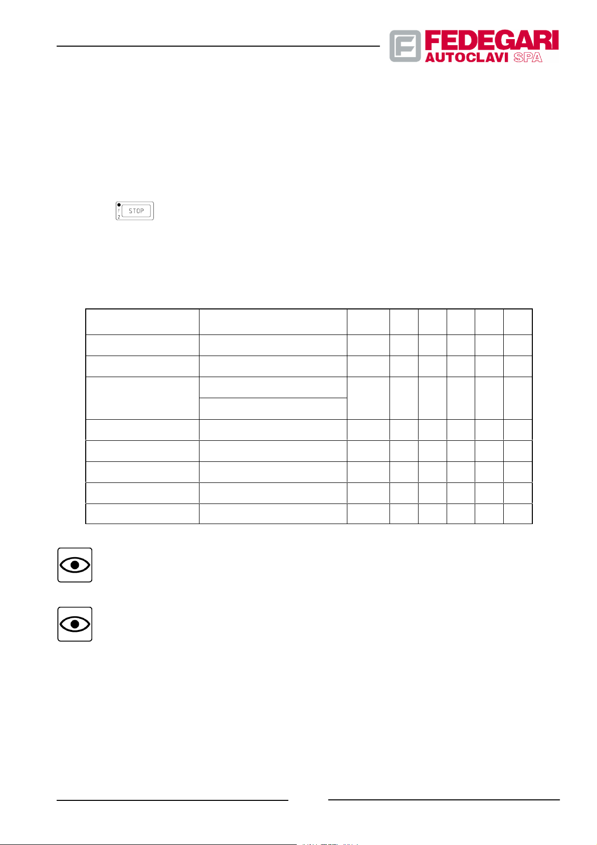
Before going on, the program checks the cover system logic, in order to assure that the operations carried out are
X
compliant with the chamber safety conditions.
When running, the program can be stopped before the sterilization process completion only through a manual
emergency control (cycle stop), by an activated alarm (due to a failure occurring during the sterilization process) or
when the machine is restarted after a black--out. In this case, the sterilizer enters an ”emergency” phase, providing a
wait state which protects the machine, the personnel and any loaded products. The sterilizer is no longer in the
emergency state and immediately reaches the cycle final phases (pressure balancing and end--of--phase), by
pressing key
.
The operator will be permitted to execute specific programs (1, 2, 3) and to select some phase sequences of the
sterilization programs only if the sterilizer features one or several of the following additional systems (Table 6.10.):
Table 6.10 -- Additional component program phase
PROGRAMS/PHASES
DESCRIPTION
Phase
No.
K20 K51 K52 K61 K62
Prg. N.1 VACUUM TEST -- X
Prg. N.2 PRESSURE TEST -- X X
DECONTAMINATION (FVA2/3)
Prg. N.3
--
HI GH PATHOGEN (FVA--HT)
Phase INITIAL VACUUM 3+4 X
Phase STEAM PULSES 5 X
Phase FINAL VACUUM 10 + 11 X
Phase COOLING FORCED 9 X
NOTE
Option K62 includes option K61.
NOTE
The operator must set up sterilization programs compatible with the machine components, fit for the
product t o be sterilized. The sterilizer software will prevent the operator from select phases,
programs or functions which are not allowed by the machine P&ID configuration.
May 2001
Phase AIR PULSES 12 X
-- 57 --
#68181 Rev.1
Page 67
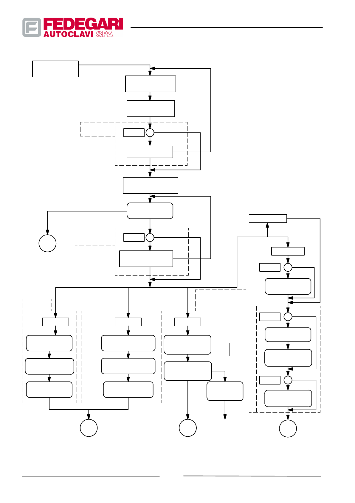
MAIN
MENU
C
PROGRAM
EXECUTION
Function
PRINTER
K81
STEAM
GENERATOR
K10
SELECT PROGRAM
(1--10)
OUTPUT
SELF--DIAGNOSIS
RESET
S6=1/0
PRINTER
CHECK OK
OK
PRINTING HEADDING
AND PARAMETRES
PHASE 1
PREPARATION
STOP
S5=1/0
CHECKING THE
STEAM GENERATOR
OK
ST ART
NOT
OK
NOT
OK
PROG. 4
PROG. 5--10
V1=1/0
VACUUM
PUMP K20
PROG. 1
PHASE 2
INITIAL VACUUM
PHASE 3
STABILIZATION
PHASE 4
VACUUM TEST
PROG. 2
PHASE 2
PRESSURISATION
OR
DECONTAMINATION CYCLE K 62
CHAMBER PRESSURE TEST K 61
PHASE 3
STABILIZATION
PHASE 4
PRESSURE TEST
PROG. 3
PHASE 6
HEATING
DECONTAMIN.
PHASE 7
STERILIZATION
DECONTAMIN.
B D
Figure 6.12--Flow chart of the sterilizer cycles (1
DECONTAMINATION
K62 FVA/F VA3
HIGH PATHOGEN
FVA--HT
CYCLE STOP OR
BLACKOUT
EMERGENCY
DECONTAM.
EMERGENCY
PHASE
MANUAL
SWITCH OFF
st part)
PRE--HEATING
V3=1/0
INITIAL VACUUM
VACUUM PUMP K 20
V6=1/0
STEAM PULSES
PHASE 2
PHASE 3
PHASE 4
TIMED
VACUUM
PHASE 5
A
#68181 Rev.1
-- 58 --
May 2001
Page 68
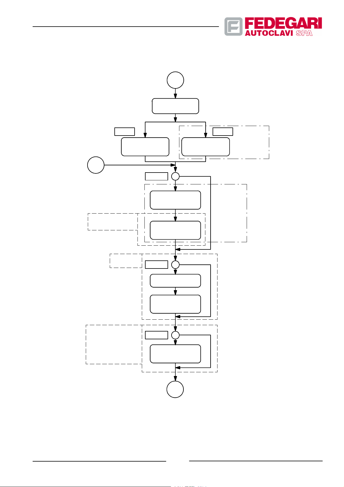
A
PHASE 6
HEATING
D
V13=0
QUICK
COOLING
UNIT K 52
VACUUM
PUMP K 20
PHASE 7a
STERILIZATION
t
V16=1/0
SPONTANEOUS
V20=1/0
FINAL VACUUM
PHASE 8
COOLING
PHASE 9
FORCED
COOLING
PHASE 10
V13=1
PHASE 7b
STERILIZATION
F
0
performed
Bowie&Dick
cannot be
performed
for
Bowie&Dick
test
cannot be
for
test
May 2001
PHASE 11
DRYING
VACUUM
VACUUM PUMP K20
(only for pressurisation
and
PRESSURISATION
UNIT K51
on increasing pulses)
V23=1/0
PHASE 12
AIR
PULSES
E
Figure 6.13 -- Flow chart of the sterilizer cycles (2ndpart)
-- 59 --
#68181 Rev.1
Page 69
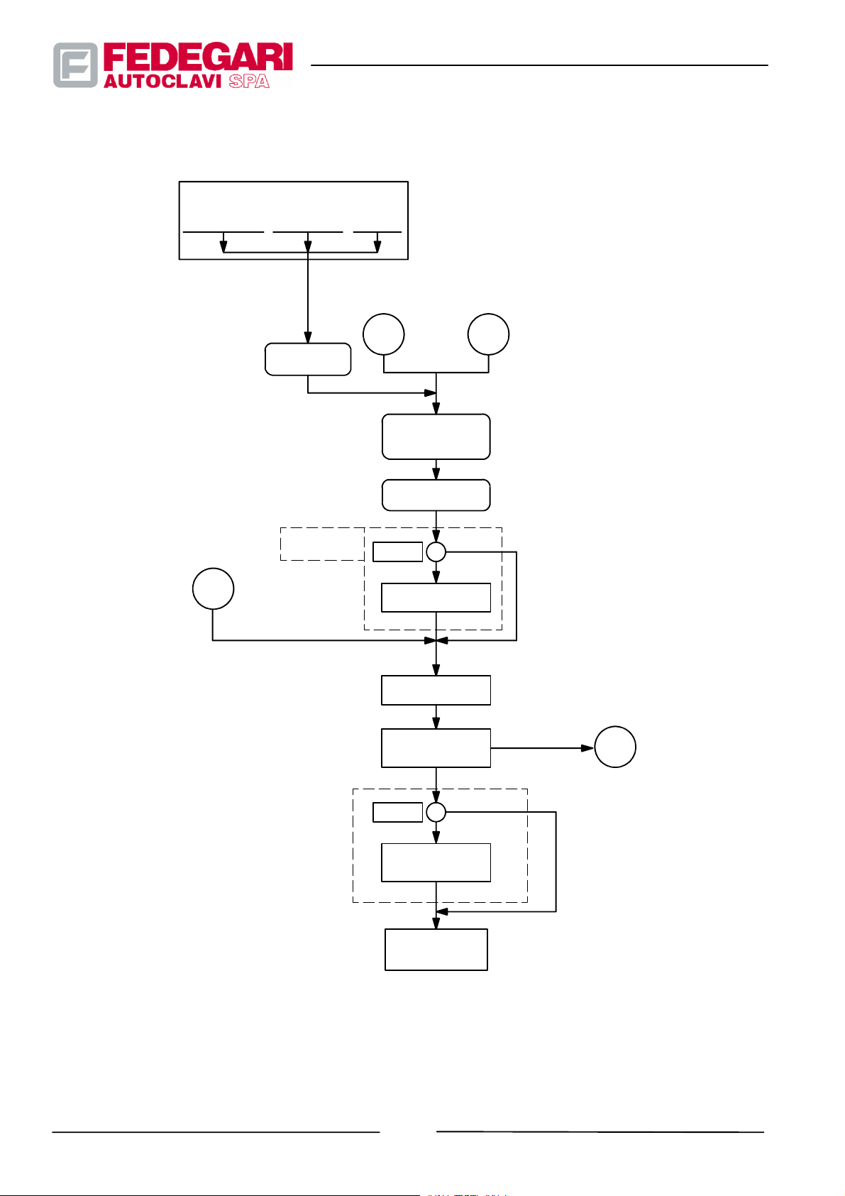
EVENTS WITH CYCLE IN
PROGRESS:
BLACK OUT ALLARME
PHASE
EMERGENCY
STOP
PRINTER
K81
STOP
CICLO
S6=1/0
PHASE 13
PRESSURE
BALANCING
FASE 14
END CYCLE
EB
C
PRINTING FINAL
DATA
OK
ALARM RESET
CYCLE
REPETITION
CONTROL
NO
S8=1/0
POWER RESET
RETURNING
THE MAIN
MENU
YES
F
#68181 Rev.1
Figure 6.14 -- Flow chart of the sterilizer cycles (3st part)
-- 60 --
May 2001
Page 70

6.4.3.2. Program parameters
The operator can select the desired phase sequence (v1, v2, ...v22) or modify some phase parameters in order to
choose the operating configuration required by simply setting proper ”program parameters”.
Program parameters are available in display and adjust mode, when accessing suitable software pages from the main
menu (see 6.5.2.).
These 10 pages, one for each program, consist of two types of parameters:
-- Phase selection parameters, allowing to enable the corresponding phase(s);
-- Phase parameters allowing to set target times and values for the phase.
The four tables below describe the program parameters of the sterilizer applications.
In particular, program parameters (5¸10) mentioned in Table 6.16 are supplied with their default values for special
uses:
-- Prg. 5 - - Solid
-- Prg. 6 -- Porous
-- Prg. 7 -- Rubber
-- Prg. 8 -- Closed box for
-- Prg. 9 -- Liquid forced
-- Prog.10 -- Spontaneous--cooling
The meaning of the table fields is the following:
-- NO: parameter identification number;
-- DESCRIPTION: parameter name;
-- FUNCTION: description of the activities managed by the parameter;
-- MIN: minimum parameter value;
materials
materials
materials
sterilization
cooling
liquids
-- DEF: parameter Default value for every program;
-- MAX: maximum parameter value;
Units of measurement of the parameter: bar (bar), centigrades (_C), minutes (min).
-- 61 --
May 2001
#68181 Rev.1
Page 71

Table 6.11 -- Program parameter list: VACUUM TEST
V1TESTPRESSUREb
No. DESCRIPTION FUNCTION MIN DEF MAX
V1 TEST PRESSURE bar Target pressure during the initial vacuum phase. 0.01 0.20 1.00
V2 STABILIZ. TIME min
Duration of the pressure stabilization phase in the
chamber.
0 2 480
V3 VACUUM TEST TIME min Target time of vacuum test in the chamber. 0 10 480
Max. pressure rise allowed during the vacuum
test in the chamber. When the chamber pressure
V4 MAX. PRESS. RISE bar
exceeds the initial pressure of the phase plus V4,
0.001 0.013 1.000
the ”LEAK TEST ALARM” is displayed and the
test fails.
Table 6.12 -- Program parameter list: PRESSURE TEST
No. DESCRIPTION FUNCTION MIN DEF MAX
Target pressure of the pressurization phase 1.00 2.00 3.00
ar
Values for FVA--HT model 1.00 5.00 5.00
V2 STABILIZ. TIME min
Duration of pressure stabilization phase in the
chamber.
0 2 480
V3 VACUUM TEST TIME min Target time of the pressure test in the chamber. 0 10 480
Max. pressure rise or drop allowed during the
chamber leak test. When the chamber pressure
MAXIMUM PRESSURE
V4
LACK
exceeds the inintial pressure of the phase plus V4
bar
or is lower than the initial pressure of the phase
0.001 0.013 1.000
less V4, the ”LEAK TEST ALARM” is displayed
and the test fails.
Table 6.13 -- Program parameter list: HIGH PATHOGEN -- SPECIFIC FOR THE FVA--HT MODEL
No.
DESCRIPTION FUNCTION MIN DEF MAX
It is the temperature that, being added to 0.2_C
represents the heating phase final target. It is also
the minimum temperature allowed during the
V10 STER. T. TEMP. _C
sterilization phase. When the chamber temperature
105.0 140.0 140.0
drops below this value, the alarm ”STER. TEMP.
LACK.” is displayed and the sterilization time is no
longer counted.
V14 STER. TIME min Duration of the sterilization phase. 0 10 3000
-- 62 --
#68181 Rev.1
May 2001
Page 72

No. MAXDEFMINFUNCTIONDESCRIPTION
V16 COOLING 0/1
It allows to enable/disable the spontaneous or
forced cooling phase.
0 0 1
V17 SPONT. COOL. TEMP. _C Spontaneous cooling phase target temperature. 50 110 140
V18 FORCED COOL TEMP. _C Forced cooling phase target temperature. 50 80 140
V19 COOL. PRESS. bar Forced cooling phase target pressure. 1.00 3.60 3.60
V20 DRYING VACUUM 0/1
It allows to enable/disable the product drying
phases (final vacuum and drying vacuum).
0 0 1
V21 PRESSURE bar Drying vacuum phase target pressure. 0.01 0.20 1.00
V22 TIME min Drying vacuum duration. 0 10 480
V23 AIR PULSES 0/1
It allows to enable/disable the air pulse phase inside
the chamber.
0 0 1
V24 PULSES NUMBER n Number of air pulses during the phase. 0 3 9
V25 PRESSURE UPPER bar Increasing pressure of air pulses. 0.10 0.95 3.00
V26 PRESSURE LOWER bar Decreasing pressure of air pulses. 0.08 0.20 3.00
Table 6.14 -- Program parameter list: DECONTAMINATION
No. DESCRIPTION FUNCTION MIN DEF MAX
It is the temperature that, being added to 0.2_Crepresents the heating phase final target. It is also the
minimum temperature allowed during the steriliza-
V10 STER. T . TEMP. _C
tion phase. When the chamber temperature drops
105.0 121.0 122.0
below this value, the alarm ”STER. TEMP. LACK.” is
displayed and the sterilization time is no longer
counted.
V14 STER. TIME min Duration of the sterilization phase. 0 10 3000
V16 COOLING 0/1
It allows to enable/disable the spontaneous or
forced cooling phase.
0 0 1
V17 SPONT. COOL. TEMP. _C Spontaneous cooling phase target temperature. 50 110 140
V18 FORCED COOL TEMP. _C Forced cooling phase target temperature. 50 80 140
V19 COOL. PRESS. bar Forced cooling phase target pressure. 1.00 3.60 3.60
V20 DRYING VACUUM 0/1
It allows to enable/disable the product drying
phases (final vacuum and drying vacuum).
0 0 1
V21 PRESSURE bar Drying vacuum phase target pressure. 0.01 0.20 1.00
V22 TIME min Drying vacuum duration. 0 10 480
-- 63 --
May 2001
#68181 Rev.1
Page 73

MAXDEFMINFUNCTIONDESCRIPTIONNo.
V23 AIR PULSES 0/1
It allows to enable/disable the air pulse phase inside
the chamber.
0 0 1
V24 PULSES NUMBER n. Number of air pulses during the phase. 0 3 9
V25 PRESSURE UPPER bar Increasing pressure of air pulses. 0.10 0.95 3.00
V26 PRESSURE LOWER bar Decreasing pressure of air pulses. 0.08 0.20 3.00
Table6.15--Listof Bowie & Dick program parameters
No
V3 INITIAL VACUUM
V4 PRESSURE
V5 TIME
DESCRIPTION FUNCTION MIN DEF MAX
Allows the enabling/disabling of the initial vacuum
0/1
condition.
End--of--phasetarget pressurevaluefor lettingair out of the
bar
chamber.
Indicates the duration of the vacuum phase inside the
min
chamber, with steam injection and air extraction.
0 0 1
0.01 0.20 1.00
0 3 480
V6 STEAM PULSES
V7 PULSES NUMBER
PRESSURE
V8
UPPER
PRESSURE
V9
LOWER
STERILIZATION
V10 STER. T. TEMP.
V1 1 STER. T. TOLER.
V14 STERILIZ. TIME
V20 DRYING VACUUM
0/1
Allows the enabling/disabling of the steam pulse phase. 0 0 1
n.
Indicates the number of steam vacuum pulses. 0 3 9
bar
Indicates the increasing pulse pressure value. 0.10 1.50 3.00
bar
Indicates the decreasing pulse vacuum value. 0.10 0.50 3.00
It is the temperature that, being added to 0.2_C represents
the heating phase final target. It is also the minimum
temperature allowed during the sterilization phase. When
_C
the chamber temperaturedrops belowthis value, thealarm
65.0 133.0 136.0
”STER. TEMP. LACK.” is displayed and the sterilization
time is no longer counted.
It is the temperature value based on which the sterilization
phase is regulated. The sterilization tolerance determines
_C
the sterilization range by adding to sterilization
temperature V10 its value.
min
Duration of the sterilization phase. 0.0 3.5 900.0
0/1
Allows the enabling/disabling of the product drying phases. 0 0 1
*
1.0 2.0 5.0
V21 PRESSURE
V22 TIME
#68181 Rev.1
bar
Pressure target during the 1st vacuum phase for drying. 0.01 0.20 1.00
min
Duration of the drying phase. 0 10 480
-- 64 --
May 2001
Page 74

No MAXDEFMINFUNCTIONDESCRIPTION
V23 AIR PULSES
Allows the enabling/disabling of the air pulse phase inside
0/1
the chamber.
0 0 1
V24 PULSES NUMBER
UPPER
V25
PRESSURE
LOWER
V26
PRESSURE
n.
Number of air pulses. 0 3 9
bar
Increasing pressure of air pulses. 0.10 0.95 3.00
bar
Decreasing pressure of air pulses. 0.08 0.20 3.00
Table6.16--Programparameterlist(PROGRAMS 5 ¸ 10)
No. DESCRIPTION FUNCTION
Allows the enabling/disabling of the
V1 PREHEATING
V2 TIME
V3 PREVACUUM
V4 PRESSURE
0/1
pre--heating phase.
min
Pre--heating phase duration
Allows the enabling/disabling of the
0/1
initial vacuum phase.
It is the end--of--phasetarget pressure of
bar
air extraction from the chamber.
Prg5Prg6Prg7Prg8Prg9Prg
0 0 0 1 1 1 0 1
3 3 3 15 15 15 0 480
1 1 1 1 0 0 0 1
0.10 0.10 0.10 0.10 0.20 0.20 0.01 1.00
10
MIN MAX
V5 TIME
V6 STEAM PULSES
V7 PULSES NUMBER
V8 PRESSURE UPPER
V9 PRESSURE LOWER
STERILIZATION
V10 STER. T. TEMPER.
Duration of the vacuum phase inside the
min
chamber, with steam injection and air
extraction.
Allows the enabling/disabling of the
0/1
steam pulse phase.
n.
Indicates the steam pulses number.
bar
Upper pressure of steam pulses.
bar
Lower pressure of steam pulses.
Itisthetemperaturewhich(addedto
0.2_C indicates the pre--heating phase
final target. It is also the minimum
temperature allowed during the
_C
sterilization phase. When the chamber
temperature drops below this value, the
alarm ”STER. TEMP. LACK.” is
displayed and the sterilization phase
time is suspended.
5 3 5 0 3 3 0 480
0 1 1 1 0 0 0 1
3 3 3 3 3 3 0 9
1.50 1.20 1.20 1.20 1.50 1.50 0.10 3.00
0.50 0.10 0.20 0.10 0.50 0.50 0.10 3.00
133 133 120 133 120 120 65 136
May 2001
-- 65 --
#68181 Rev.1
Page 75

No.
V11 STER. T. TOLER.
V13 CONTROL BY F0
FUNCTIONDESCRIPTION
It is the temperature value based on
which the sterilization phase is
regulated. The sterilization tolerance
_C
determines the sterilization range by
adding to sterilization temperature V10
its value.
*
Allows the selection of the type of
regulation used during the sterilization
phase:
-- “0 ” ti me
_C
-- “1” control with F0
Control is carried out during the heating
phase
Prg
10
9
8
7
6
5
2.0 2.0 2.0 2.0 2.0 2.0 1.0 5.0
0 0 0 0 0 0 0 1
MAXMIN
Prg
Prg
Prg
Prg
Prg
V14 STER. TIME
V15 F0 TARGET
V16 COOLING
SPONT. COOL.
V17
TEMP.
FORCED COOL.
V18
TEMP.
V19 COOL. PRESS.
V20 DRYING VACUUM
V21 PRESSURE
V22 TIME
min
Sterilization phase duration.
Duration of the heating/sterilization
min
phase in F0.
Allows the enabling/disabling of the
0/1
cooling phase.
Spontaneous cooling phase target
_C
temperature.
Forced cooling phase target
_C
temperature.
Chamber pressure used during the
bar
forced cooling phase.
Allows the enabling/disabling of the
0/1
product drying phases.
Target pressure during the 1st drying
bar
vacuum phase.
min
Drying phase duration.
10 10 20 10 15 15 0 3000
8 8 8 8 8 8 0 9999
0 0 0 0 1 1 0 1
115 110 110 110 120 80 50 140
80 80 80 80 80 80 50 140
2.20 2.20 2.20 2.20 2.20 2.20 1.00 3.40
1 1 1 0 0 0 0 1
0.20 0.10 0.10 0.20 0.20 0.20 0.01 1.00
15 20 20 10 10 10 0 480
V23 AIR PULSES
V24 PULSES NUMBER
V25 PRESSURE UPPER
V26 PRESSURE LOWER.
#68181 Rev.1
Allows the enabling/disabling of the air
0/1
pulse phase in the chamber
n.
Air pulses number.
bar
Upper pressure of air pulses.
bar
Lower pressure of air pulses.
-- 66 --
0 1 1 1 0 0 0 1
3 3 3 3 3 3 0 9
0.95 0.90 0.90 0.90 0.95 0.95 0.10 3.00
0.20 0.20 0.10 0.10 0.20 0.20 0.08 3.00
May 2001
Page 76
* The sterilization range (ranging between Tster_min and Tste r _max)andtheTreg Regulation temperature
A
are defined using only two parameters:
No.
DESCRIPTION MIN DEF MAX
V10 STER. T. TEMP. (Tster) (_C) 65.0 120.0 / 133.0 136.0
V1 1 STER. T. TOLER. (Ttoll) (_C) 1.0 2.0 5.0
REGULATION TEMPERATURE (Treg) (_C) 65.5 121.0 / 134.0 137.5
REGUL
TION RANGE
Tst e r_max
Treg
Ttoll
Tst e r =
Tst e r_min
where:
D Tster_min = Tster
D Tster_max = Tster + Ttoll
D Treg = Tster + Ttoll / 2
6.4.3.3. General system parameters
During the execution of the sterilization program, the machine is managed by specific parameters, as well as by a
series of general parameters (SYSTEM PARAMETERS) controlling the activities and functions common to every
sterilization process.
Table 1.10 below shows the general parameter list and includes a short description of their functions.
The meaning of the table fields is the following:
-- NO: parameter identification number
-- DESCRIPTION: parameter name
-- FUNCTION: description of the activities managed by the parameter
-- MIN: minimum parameter value
-- DEF: parameter Default value
-- 67 --
May 2001
#68181 Rev.1
Page 77

-- MAX: maximum parameter value
Table 6.17 -- General system parameters
No.
1a STERIL. --P TOLER.
1b STERIL. +P TOLER.
2
3
4 CYCLE END TIME sec
DESCRIPTION FUNCTION MIN DEF MAX
MIN. P. BALANCE
Pmaxb
MAX. P. BALANCE
Pmaxb
During the product heating and sterilization, the
chamber pressure is regulated according to the
bar
value ofthese 2 parameters and ofthe program
parameter ”STER. TEMP.”, allowing to obtain the
regulation pressure.
It is the minimum pressure inside the chamber
bar
during pressure balancing and end--of--cycle
phases, to enable the cover opening.
It is the maximum pressure inside the chamber
bar
during pressure balancing and end--of--cycle
phases, to enable the cover opening.
It indicates the cycle end phase duration, in
seconds.
0.02 0.03 0.10
0.00 0.00 0.10
0.50 0.95 1.00
0.55 1.05 1.10
0 10 999
It can take only values 0 and 1. Number 1 must be
5 STEAM GENER. 0/1
set when the machine features an autonomous
0 0 1
steam generator.
It enables printing of the cycle data during the
6 PRINTER 0/1
sterilization program execution. Value 1 is set only
0 0 1
if the machine is equipped with a printer.
It allows to set the printing interval for the cycle data
during the execution of the sterilization program.
7a PRINTER INTERVAL sec
Operating only if the machine is provided with a
30 60 9999
printer and the ”PRINTER” general parameter is set
to 1.
It allows to set the printing interval for the cycle data
PRINTING INTERVAL IN
7b
STERILIZATION
during the execution of the sterilization program.
sec
Operating only if the machine is provided with a
printer and the ”PRINTER” general parameter is set
30 999 9999
to 1.
On the cycle end phase completion, the machine
8 POWER RESET 0/1
can be automatically switch off only if this parameter
0 0 1
is set to 1.
Valuetobesetto1inordertoenablethecontrolof
9 CHECK FINAL T 0/1
system parameter ”FINAL TEMPERAT.” on heat
0 0 1
probe T001.
It is thetemperature (measured by heat probe T001)
10 FINAL TEMPERAT. _C
above which the cover does not open. This control
is operating only if the parameter ”CHECK FINAL
0 70 95
T” is set to 1.
11 DOOR INVERSION. _C Not applicable 0 0 1
12 REPEAT CYCLE. _C
If this option is enabled, the cycle can be repeated
up to 20 times.
0 0 20
#68181 Rev.1
-- 68 --
May 2001
Page 78

6.4.4. Operating phases
The operator manages the sterilization process according to the following main operating phases:
-- Switching on and initial controls;
-- Operation enabling;
-- Product loading;
-- Pro gra m s tar ting ;
-- Process control;
-- Product unloading;
-- Disabling or switching off.
To process the product, these operating phases must be carried out in sequence. Of course, to execute these
operating phases, the operator must be acquainted with a series of auxiliary functions, such a:
-- Logic of access to the menu pages;
-- Cover opening logic;
-- Printing functions;
-- Step--by--step and cycle stop functions;
.
-- F
0
6.4.4.1. Menu page access logic
The main menu is automatically displayed when the controller has been fed.
Other pages can be accessed:
-- by entering the number corresponding to the option selected through the main menu or another menu ;
-- by pressing key
To return to the previous menu:
-- Pre ss ke y
-- Pre ss ke y
,
;
.
6.4.4.2. ”Step--by--step” and ”Cycle stop” functions
During the sterilization program execution, until the process is over, the operating interaction is inhibited, except for
monitoring the chamber parameters.
In case of failures, the operator is allowed to intervene in the process in progress through the specific functions
(STEP--BY--STEP and CYCLE STOP) described below.
STEP--BY--STEP Function
To enable it, at the 3 highest password levels, .
-- 69 --
May 2001
#68181 Rev.1
Page 79
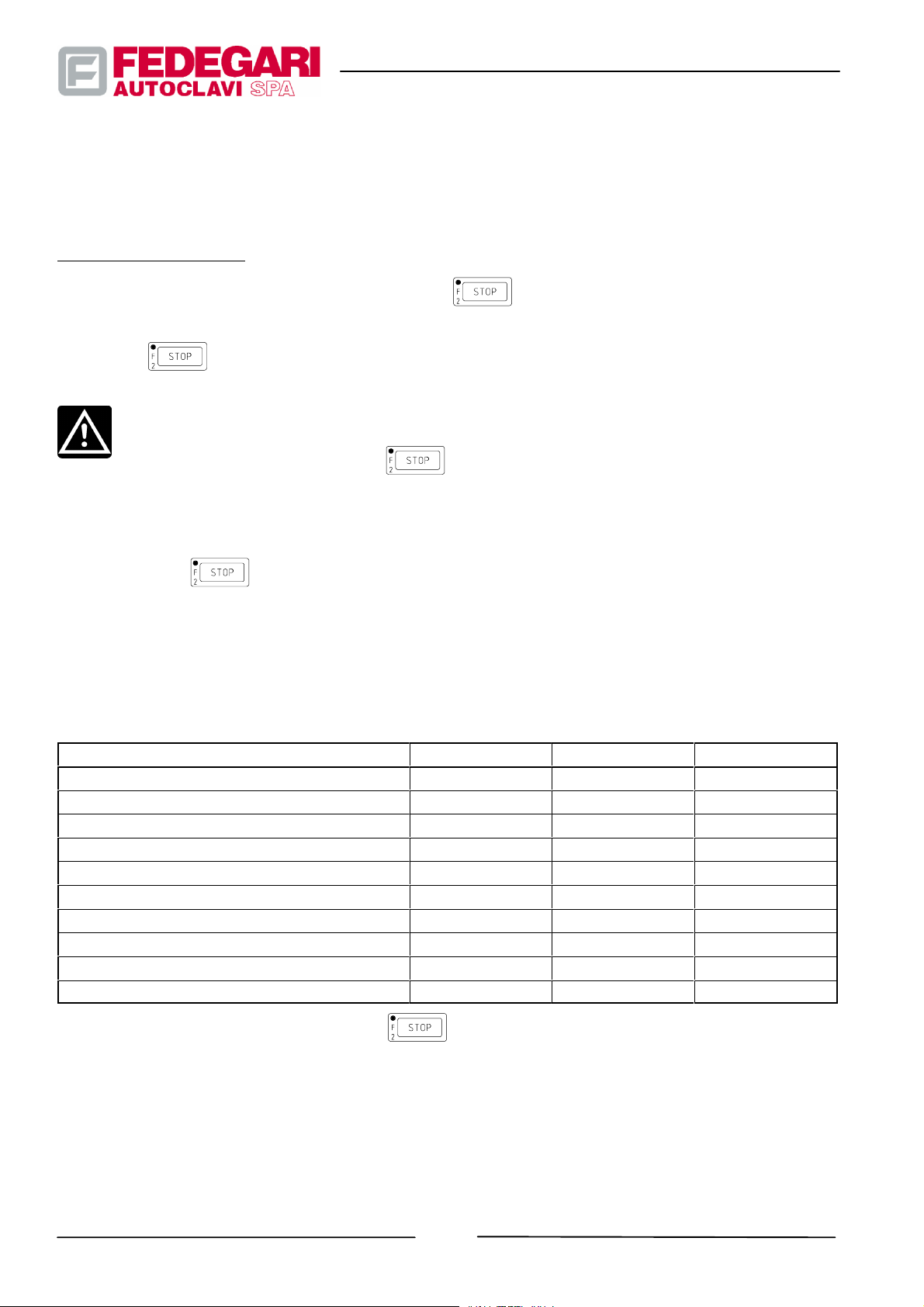
It allows to have access to the next operating phase, by blocking the controls related to the operating phase in
progress, without waiting to reach the end--of--phase set value. The alarm ”PHASE STEP UTILIZED” is displayed and
printed.
CYCLE STOP function
To enable it, at the 3 highest password levels, press key .
It allows to enter the emergency phase. The alarm ”MANUAL PROGRAM--STOP” is displayed and printed. When
pressing key
CAUTION !
Pressing this key is likely to damage
liquids kept in tight containers, a pressure differential dangerous for containers is caused when
reaching atmospheric pressure.
The pressure differential makes liquids boil even though they are kept in containers which are not
tight, but feature protective filters.
Press key
atmospheric pressure, and when the product temperature is < 70°C.
STEP--BY--STEP and CYCLE STOP functions will be enabled in all phases except for the cases mentioned in the
following Table
Preparation all no no
Pressure balancing all yes (*) no
Cycle end all no no
Phase emergency all no no
Black Out emergency all no no
Decontamination program emergency 3 no no
Decontamination program heating 3 yes yes
Decontamination program sterilization 3 no yes
Spontaneous cooling 3--10 no yes
Forced cooling 3--10 no yes
, the system has access to the Pressure Balancing and Cycle End functions.
the batch in all cases in which, during sterilization of
only after having checked that the chamber pressure has spontaneously reached
Table 6.18 -- Step--by--Step and Cycle Stop enabling
PHASE PRG. STEP--BY--STEP CYCLE STOP
(*) When forced exit is required, having pressed during the EMERGENCY phase, if no pressure balance is
reached.
6.4.4.3. F
This parameter is the sterilization time at 121,11° C or, better, the time related to a sterilization process carried out at
another temperature and duly calculated for a 121,11°C process, so that it has an equivalent lethal thermal power, i.e.
#68181 Rev.1
0
-- 70 --
May 2001
Page 80

it proves effective in killing microbes ( probability of finding 1 non sterile unit out of a certain number of PNSU units).
The calculated F0 is totalled by processing the temperature values measured by the heat probe if the measured
temperature is ranging from 100°C to 143, 9°C.
F0 value is updated every second, displayed and printed when the cycle is over in order to check the lethal doses
applied in the point monitored by T001.
F0, value is also used to regulate the sterilization phase through proper program parameters.
6.4.4.4. Opening/closing logic of the cover
Opening
To open the sterilizer:
-- No process cycle must be in progress;
-- Both the pressure transducer connected to the sterilizer control system and the electromechanical safety
pressure switch must indicate that pressure inside the chamber is equal to atmospheric pressure again;
-- The heat probe located inside the chamber measures a temperature lower than the safety set value (this is
possible only if the system parameter ”CHECK FINAL T” has been set);
If the above mentioned conditions have been met, the operator can enable compressed air exhausting from the
seal housing. The ”Opened cover” LED on the operator panel will indicate that the cover can be turned to unload
the batch.
system
Closing system
Manually turn the cover in order to close it, while pressing the safety lever which releases it.
When the cover has reached the closing position, its hooking lever is released. The cover cannot turn and the safety
limit switch is pressed.
The limit switch allows the system to send the control required to the solenoid valves allowing to supply compressed
air to the seal housing of the sealing system.
The cover being properly positioned, a control sent by the operator enables the compressed air supply to the seal
housing, in order to close the chamber and to lock the cover.
When the chamber is closed, the LED located near the
If the cover is not perfectly closed and the cycle is in progress, a specific alarm message (OPEN DOOR IN CYCLE) is
displayed causing the cycle to be stopped.
keyswitcheson.
6.4.4.5. Printing function (if a printer is available)
The machine is equipped with a printer to print cycle data.
The preset printing enabling and intervals are shown in the general parameter page.
The printing report includes the following information:
-- 71 --
May 2001
#68181 Rev.1
Page 81

1. HEADING
-- FEDEGARI AUTOCLAVI
-- Program start--up DATE AND TIME
-- STERILIZER NF (serial number entered by FEDEGARI’s engineers through a reserved menu)
-- Message about the number of repetitions set
-- Notes on the sterilized product
-- Notes on the batch program
2. PROGRAM NUMBER AND PROGRAM PARAMETER LIST
3. CYCLE DATA
Displayed data are printed according to set intervals, calculated based on the phase time.
4. ALARM MESSAGES:
-- ALARM NAME
-- detected ALARM ST ATE (ON, OFF, ACK)
-- ACK (acknowledgment request), if activated by the alarm
-- Data recording DATE and TIME
5. FINAL DATA
-- CYCLE NUMBER (progressive program time)
-- PROGRAM TIME (overall program time)
-- STERILIZATION TIME (time of exposure to correct temperatures during the sterilization phase)
F
-- Fo CALCULATED (Final
-- Message about the test or sterilization result
-- Message about the number of repetitions set
-- DATE AND TIME (Program end time)
-- SIGNATURE (Space for the operator’s signature)
When no cycles are in progress, the page displayed can be printed through the
value)
0
command.
6.4.5. Operating procedures and warnings
CAUTION!
The operator must work s o that all controls are easy to reach and suitably positioned from an
ergonomic viewpoint. Keep the working place f ree from any equipment, other than t he tools required
to control the sterilizer. Before starting the machine, do not allow unauthorized people to stay near
the sterilizer.
#68181 Rev.1
-- 72 --
May 2001
Page 82
Procedures
The main operating phases mentioned in the previous section thoroughly identify the sequence of procedures carried
out by the operator in order to use, step--by--step, the sterilizer according to its functions.
Every operating phase consists of several sections, based on the above mentioned sequence.
NOTE
Should the graphic representation of the menus and pages supporting these instructions include
more than 4 lines, the remaining text will be in a shadow area.
To display the whole text, use keys
NOTE
Some pages displayed to support the manual instructions show information, values and parameters
by way of example. They could not be installed on your sterilizer.
and .
Instructions for use
This section provides useful information and warnings for operating procedures. However, these procedures will also
include specific warnings, whenever it is required by the type of procedure to be carried--out.
WARNING!
The emergency stop mushroom--head button must not be used improperly. Use it carefully, without
forcing it, to avoid damaging it.
NOTE
All characters inconsistent with selectable options cannot be entered, as they are not accepted by
the controller.
6.4.5.1. Switching on and initial checks
Lighting the
Check that the workplace is properly lighted (if possible, with natural light), to allow the operator to identify the machine
command and control devices.
workplace
Checking supply systems
Check that the main switch is in the “I” position. If this switch is in the”O” position, feed the machine by turning its lever
until it is in the “I” position.
Control enabling and acquisition
Turn on the master switch located on the front side of the machine. A message (in English) is displayed for a few
seconds (see Figure 6.15) showing the panel software version, followed by the main menu (see Figure 6.16) with the
list of operating and maintenance selectable options.
-- 73 --
May 2001
#68181 Rev.1
Page 83
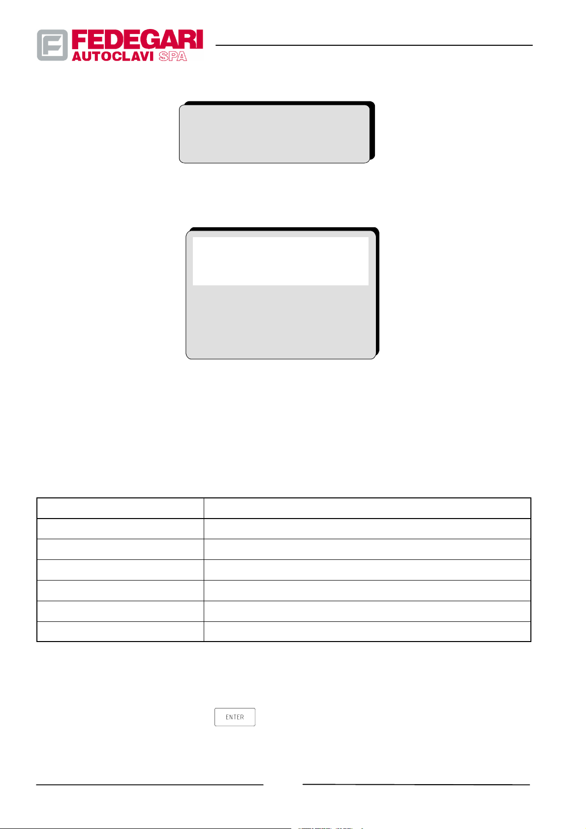
T line CODICE FIRMWARE
OPERATION MODE
Figure 6.15 -- Initial message
DD/MM/YY hh : mm : ss
MAIN MENU
1. SELECT PROGRAM
2. MODIFY PROGRAMI
3. AUTODIAGNOSE
4. SYSTEM PARAMETERS
5. AUTOCLAVE DATA
6. AUXIL. FUNCTIONS
Figure 6.16 -- MAIN MENU
To select the main menu options, press the key corresponding to the number displayed next to the option.
Table 6.19 shows the selectable options, corresponding to the sections dealing with the selection topics.
Table 6.19 -- Menu selection and related sections
OPTION
RELATED SECTIONS
SELECT PROGRAM 6.4.5.3. Program start
MODIFY PROGRAM 6.5.2. Program parameter configuration
AUTODIAGNOSE 6.6.4. Self--diagnosis
SYSTEM PARAMETERS 6.5.3. Changing general parameters
AUTOCLAVE DATA 6.6.6. Sterilizer data
AUXIL. FUNCTIONS 6.7. Auxiliary functions
6.4.5.2. Panel functions and operation enabling
Starting from the main menu, press key for at least 2 seconds to have access to the function menu of
man/machine interface, known as ”PANEL FUNCTIONS” (see Figure 6.17).
-- 74 --
#68181 Rev.1
May 2001
Page 84

PGS ALM EVT PSW CFG
TIM ACC SYS EXT
Figure 6.17 -- PANEL FUNCTIONS menu
Through their enabling the operator can:
-- enter the password (PSW);
-- check the operator panel performance and adjust the display brightness (SYS);
-- set the system date and time (TIM);
-- Enter configuration data (PGS);
-- Alarm list (EVT);
-- Load the SW on the operator panel (CFG);
-- Exit from the menu (EXT)
Functions ACC and ALM are not used.
The table below shows the password level required to have access to every panel function as well as the section
dealing with it.
Table 6.20 -- PANELFUNCTIONS, access levels and related paragraphs
OPERATOR PANEL
FUNCTIONS
PSW -- a ll 6.4.5.2 . Panel functions and operation enabling
SYS -- a ll 6.6.3. Monitoring the operator panel
TIM -- FEDEGARI DEVELOPER
PGS -- FEDEGARI DEVELOPER
EVT -- a l l 6.6.5. Alarm list
CFG -- FEDEGARI DEVELOPER -EXT -- a l l --
ACCESS LEVELS REFERENCE SECTIONS
6.6.2. Changing date and time
-- FEDEGARI PERSONNEL
-- USER SUPERVISOR
6.6.6. Sterilizer data
-- FEDEGARI PERSONNEL
Operation enabling
To use the machine, the operator must enter his code (password) as follows:
-- 75 --
May 2001
#68181 Rev.1
Page 85
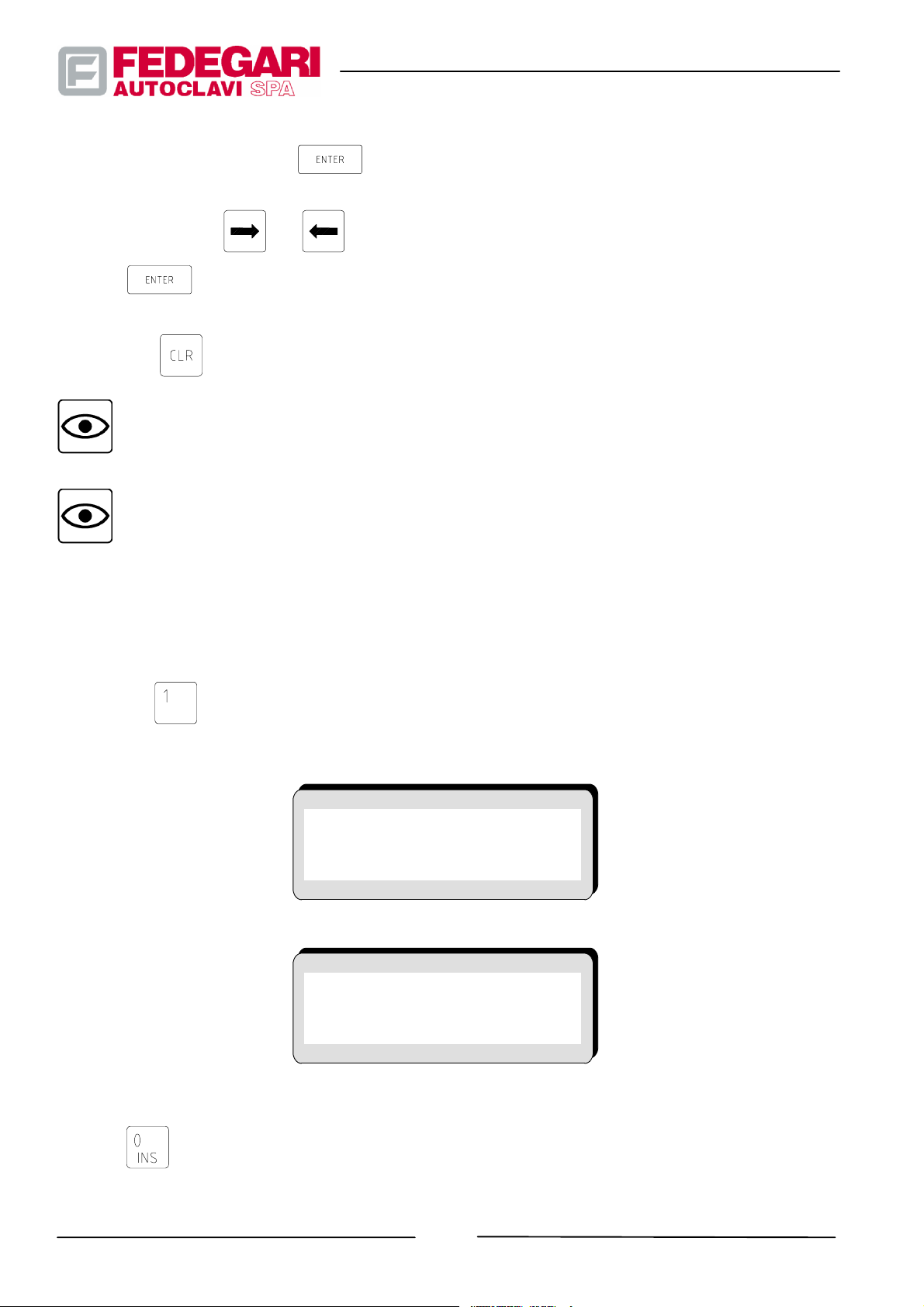
1. From the main menu, press key
Figure 6.17);
for at least 2 seconds. The PANEL FUNCTION menu is displayed (see
2. Move with the keys,
3. Press
to confirm the selected option. A page is displayed to enter the access code;
and light function PSW;
4. Key in your password consisting of four numeric characters;
5. Press key
to confirm the password and to return to the main menu.
NOTE
For your privacy, the controller does not display the numeric characters entered and the code does
not appear on the screen.
NOTE
When entering password 0000 or another password that is not recognized as programmed in the
PASSWORD MODIFICATION function, the system will automatically configure at STAND--BY level. To
return to the condition of use provided for the machine, re--insert one of the programmed keys, such
as USER or SUPERVISOR.
6.4.5.3. Program start
1. Press key to select option ”SELECT PROGRAM” from the main menu. The page ”SELECT PROGRAM” is
displayed (see Figure 6.18) and you are required to enter a number corresponding to the program to be run.
If option ### Cycle repetit. is disabled
SELECT PROGRAM
Press <INS> and insert
theProgramNr.=>“ 0”
If option ### Cycle repetit. is enabled
SELECT PROGRAM
Press <INS> and insert
theProgramNr.=>“ 0”
Cycle Repetitions : ----
Figure 6.18 -- SELECT PROGRAM menu
2. Press
(the numeric field is blinking) and key in the number corresponding to the program selected. Press
#68181 Rev.1
-- 76 --
May 2001
Page 86
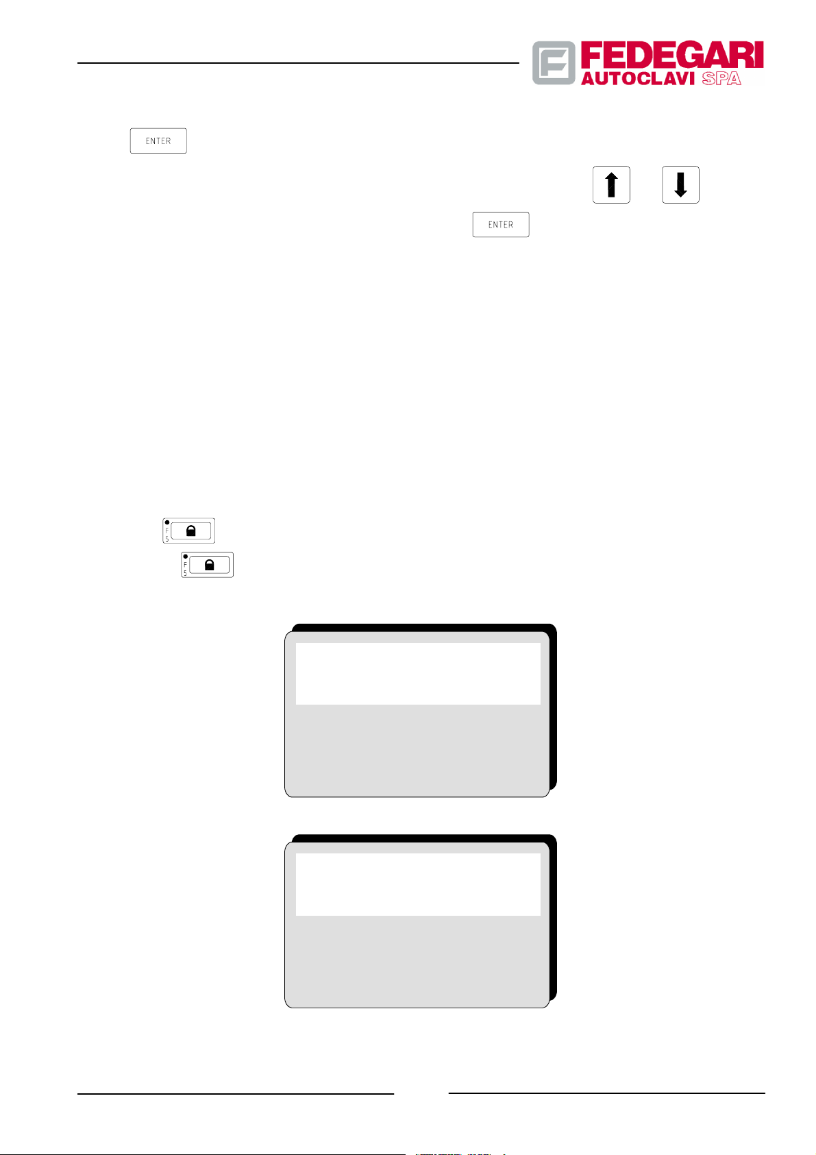
key
to confirm.
3. If option ### Repeat Cycles is enabled, select the ”Repeat Cycle” field with keys
Enter the desired number of repetitions (max. 20). Press the
key to confirm.
and .Digitareil
The controller will start the program, having checked that:
-- The selected program is enabled by the machine software configuration;
-- The printer, if any, is available, for cycle printing (general parameter PRINTER set to 1).
After the above mentioned checks, the controller displays the page corresponding to the first program phase, the
”PREPARATION” (see Figure 6.19).
The operator must make sure that the batch has been loaded in the chamber.
If it is not so, he will load it (see Section 6.4.5.4.) and close the cover as follows:
-- Turn the cover while pressing the safety lever which keeps it released until the cover is closed (the microswitch
controlling the cover closing is triggered);
-- Pre ss key
key lights up
on the keyboard, to let compressed air in the seal housing. When the LED located next to the
, the system receives the message that the chamber is closed and tight.
If option ### Cycle repetit. is disabled
P 0 PREPARATION
< AUXILIARY MESSAGE >
START: run ---------------STOP: exit ---------------T 000.0 T2 000.0 P 0.00
Delayed start:
DD/MM/YY hh/mm/ss
00--00--00 00:00:00
00--00--00 00:00:00
If option ### Cycle repetit. is enabled
P 0 PREPARATION
< AUXILIARY MESSAGE >
START: run ---------------STOP: exit REP----/---T 000.0 T2 000.0 P 0.00
Delayed start:
DD/MM/YY hh/mm/ss
00--00--00 00:00:00
00--00--00 00:00:00
May 2001
Figure 6.19 -- PREPARING the sterilization cycle
-- 77 --
#68181 Rev.1
Page 87
4. Press key
”progressive program number” increasing and printed when the cycle is over (provided a printer has been
installed and enabled). From now on, until the sterilization process is over, operating interactions other than
chamber parameter monitoring are inhibited, except for CYCLE STOP and STEP--BY--STEP functions (enabled
by Password).
NOTE
To return to main menu, without starting the sterilization program selected and increasing the
to complete the “PREPARATION” phase and to start the sterilization process, with register
progressive instruction register, press key
NOTE
After the machine has been prepared, the operator can enable the sterilization program only if the
cover is closed and the autonomous steam generator,properly installed, ha s given the controller the
signal ”generator ready”.
NOTE
The machine can be loaded at any time after cover opening, also before its starting.
CAUTION!
To avoid pouring and/or stacking the product, check that its containers are perfectly fitted into the
machine chamber before closing the cover.
6.4.5.4. Batch loading
instead of key .
1. Remove the heatprobe(s) from the sterilization chamber;
2. Place the baskets with the product to be processed inside the chamber;
3. Position the f lexible heat probe T001 and the auxiliary heat probe, if any, in the upper basket, so that their metal
points touch the product.
NOTE
If the product to be sterilized consists of a liquid solution inside tightened bottles, the heat probe
must be placed inside a sample bottle filled with deionized water. The sample bottle, positioned
inside the chamber, in the upper basket, must be prepared according to the product characteristics.
CAUTION!
When extracted from the machine, bottles with more than 70°C internal temperature are likely to
explode, thus endangering the operators. Therefore, to sterilize solutions kept in tightened bottles,
-- 78 --
#68181 Rev.1
May 2001
Page 88

select only sterilization processes providing a suitable final cooling phase and sterile air
counterpressure, which guarantee safety during the product extraction. The maximum safety
temperature allowing to open the cover must be set at <70°C and the parameter ”CHECK FINAL T”
must be activated by setting value ”1”.
CAUTION!
To sterilize heat--sensitive products use containers with homogeneous size.
CAUTION!
If product containers have different sizes, place the heat probe in the largest c ontainer.
CAUTION!
Check that the heat probe cable(s) have been properly fitted in the chamber before closing the cover.
6.4.5.5. Process control
The operator can check the sterilization process in progress by reading the dedicated page displayed, i.e. the
”process page”.
This page includes and shows information based on two main categories: the first, known as ”control parameters”,
supplies useful information (data allowing to identify the program and the phase in progress, set threshold values -pressure, temperature, time -- as well as their related values, measured and processed in real time inside the
sterilization chamber.
The second category concerns information named ”alarm messages” and auxiliary messages.
Control data
During every phase, the control page informs the operator about:
-- the number of the run program;
-- the name of the phase in process;
-- the preset threshold value (pressure, temperature or time), representing the target value of the phase in progress,
starting the next phase;
-- the temperature (°) measured in the sterilization chamber by heat probe T001;
-- the pressure (bar) measured by pressure transducer P001;
-- 79 --
May 2001
#68181 Rev.1
Page 89
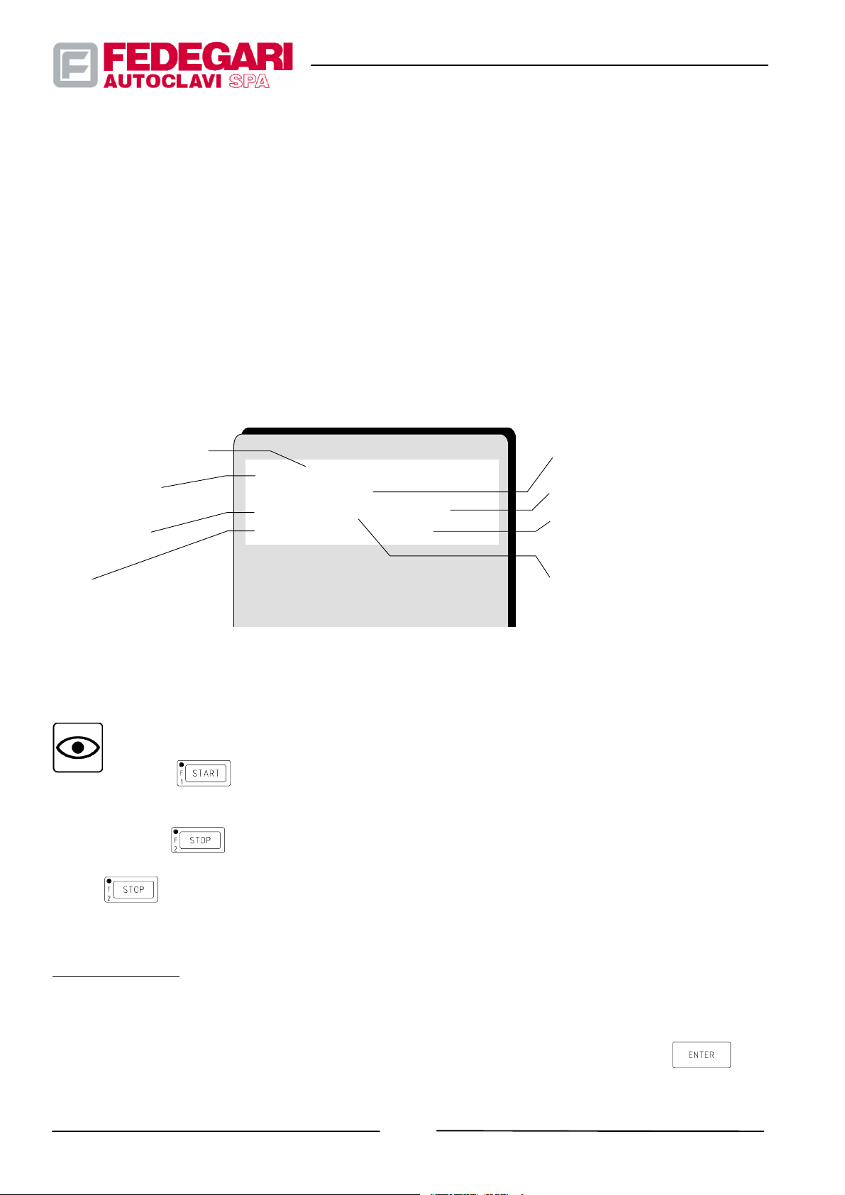
-- the phase time;
-- F
value, totalled by processing the temperatures measured by heat probe T001). It is calculated only if the
0(F0
machine features the option ”calculation and control with F
If it is not so, F
is given value 0);
0
”.
0
-- the temperature (°) measured in the sterilization chamber by heat probe T005 (if Option K80 is available);
-- sterilization time “ts” (only during the sterilization phase);
By way of example, Figure 6.20 shows the process page of the HEATING phase.
If the machine is equipped with a printer enabled, the above mentioned process information can be displayed and
printed at the beginning of every phase, according to the printing intervals set in the general parameters.
PHASE IN PROGRESS
PROGRAM IN
PROGRESS
PHASE TIME
Fo
P0 HEATING
=>T : 000.0 _C
t000.00 T000.0 P0.00
Fo 0.000 T2 000.0
PHASE-END TARGET
CHAMBER PRESSURE
HEAT PROBE T005
TEMPERATURE USED ONLY
FOR MONITORING
HEAT PROBE T001
TEMPERATURE USED ONLY
FOR CONTROLLING THE
PHASES
Figure 6.20 -- Control page concerning the HEATING phase
NOTE
Press key
at the 3 highest levels to enable the STEP--BY--STEP function. This function
allows to pass from the phase in progress to the next one. Alarm ”PHASE STEP UTILIZED” is
displayed and printed.
Press key
at the 3 highest levels to enable the CYCLE STOP function. This function allows to
enter the emergency phase. Alarm ”MANUAL PROGRAM--STOP” is displayed and printed. When key
is pressed, the system enters the pressure balancing and cycle end phase.
Alarm messages
The sterilizer features up to twenty different alarms, displayed together with their short description and printed in real
time if a printer is available.
All alarms raised generate visual and acoustic warnings which can be deactivated by pressing the
key.
#68181 Rev.1
-- 80 --
May 2001
Page 90
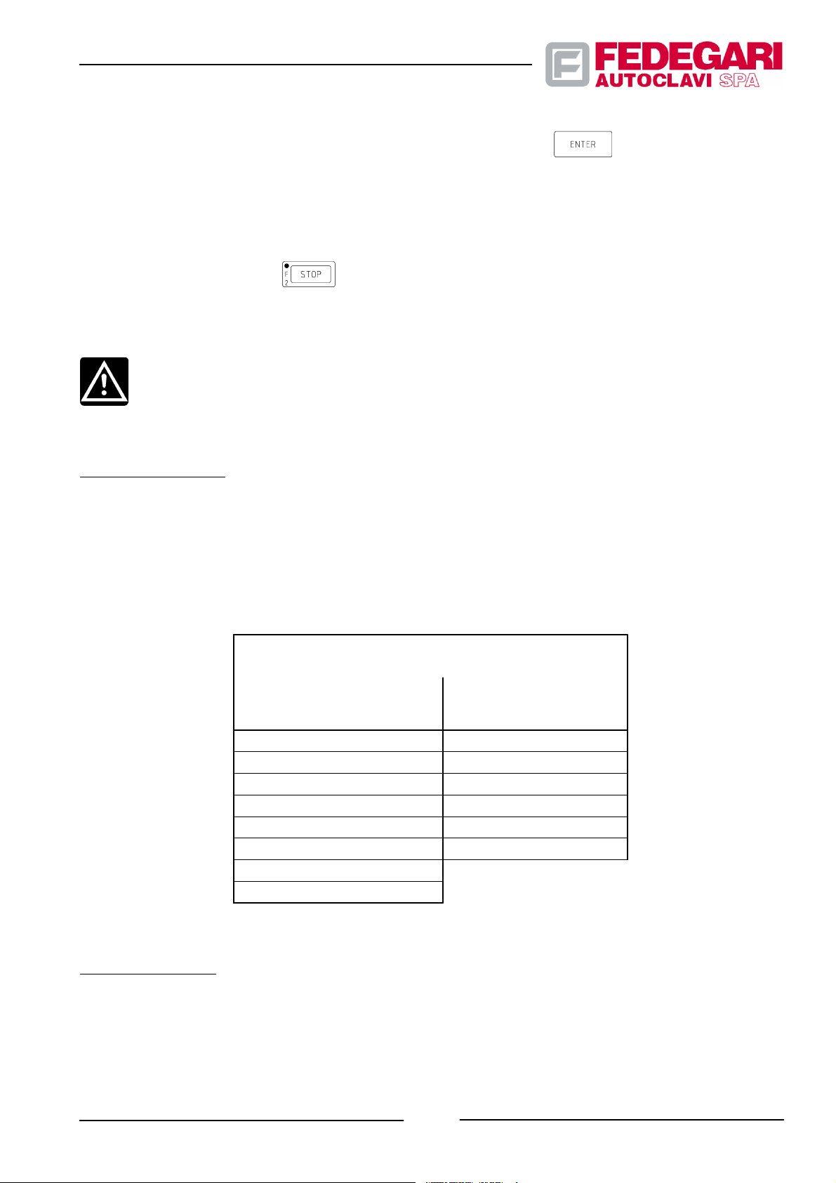
If the activated alarm must be acknowledged (ACK) the operator must hold the
Such alarms are defined as system alarms when they concern general safety tools or conditions or as phase alarms
when they are related to the execution of specific phases.
Top level alarms, e.g. the alarm indicating that the cover is not perfectly closed during the process, stop the cycle.
Therefore, the autoclave enters the emergency phase, during which it is stopped n full safety.
key down for a few seconds.
In this EMERGENCY phase, key
The machine described in this manual can enable, based on its configuration, all (full optional machine) or part of the
alarms listed in Table 7.1 (see Section 7.1.).
CAUTION!
The operator must be perfectly acquainted with the meaning and importance of the machine alarms.
allows the operator to enter the pressure balancing and cycle end phase.
Auxiliary messages
Auxiliary messages consist of short text lines that are displayed in some screens to inform the operator about the
machine and door state, as well as about the sterilization/test result.
The tables listing possible auxiliary messages and the relative screens are the following:
Tables 6.21 -- Auxiliary messages
AUXILIARY MESSAGES
displayed in screens:
MAIN MENU FOR
CYCLE END PREPARATION
READY TO START
CYCLE IN PROGR.
DOOR OPENING OK
DOOR OPEN
GENERATOR NOT READY! DECONTAMINAT. FAILED
CONTAMINATION--LOCKED ! DECONTAMINATION OK
DELAY!
REP ----/----
FINAL DATA
TEST FAILED
STERILIZATION FAILED
TEST OK
STERILIZATION OK
Emergency phase
The sterilizer enters the emergency phase when one or several failures take place during the sterilization process, or
when the machine is restarted after a black--out or through a manual command.
The emergency makes all valves close and stops all motors, with the sterilizer on stand--by.
May 2001
-- 81 --
#68181 Rev.1
Page 91
This state protects the machine, the personnel and the batch.
The events causing the emergency phase, as well as the messages displayed for every phase and the procedures to
exit from the emergency state are listed below.
Black--out emergency
The system enters the emergency phase when the sterilizer is restarted after a black--out.
Black--out starting and end time is displayed together with the sterilization chamber temperature, pressure and phase
time.
Press key
CAUTION!
Before entering the pressure balancing phase, check that temperature and pressure conditions
allow for the operations required without damaging the batch.
In particular, let liquid pr oducts cool before pressing the key
to enter the pressure balancing and cycle end phase or the decontamination emergency phase.
.
Decontamination program emergency
During the sterilization program execution, when function CYCLE STOP is activated during heating or sterilization, or
when the cycle in progress is stopped by an alarm before decontamination (heating and sterilization phases), the
sterilizer enters the emergency phase.
The sterilization chamber temperature and pressure as well as the phase time and the progressive cycle number are
displayed. The operator can only switch the machine off.
When the machine is turned on again, the operator panel’s display shows the ”CONTAMINAT. LOCK !” message, that
indicates that the valves involved in the pressure balancing in the chamber (E003 when the pressure in the chamber is
below the minimum balancing pressure and E006 when the pressure in the chamber exceeds the maximum balancing
pressure) are locked to prevent any microbiologic contamination hazard for the rooms and the products. Therefore,
after solving the problem that has caused the decontamination Emergency,the operator can relaunch the cycle, being
sure that no contaminated product has been in contact with the exterior of the chamber.
If the emergency causes result in the opening the chamber cover, the operator can manually remove the lock on the
chamber’s pressure balancing.
Press the
#68181 Rev.1
keys in the AUXILIARY FUNCTIONS menu. The following message is displayed:
CONTAMINATION LOCK
LOCK ACTIVATED !
Atmospheric Balance
Unlock/Lock (0/1) 1
Figura 6.21 -- CONTAMINATION LOCK message
-- 82 --
May 2001
Page 92

Press
: the lock is removed. To return to the main menu, press the key.
Phase emergency
The system enters the emergency phase when function CYCLE STOP is selected or whenever an alarm stops the
cycle in progress.
The sterilization chamber temperature and pressure are displayed together with the phase time.
Press key
to enter the pressure balancing and cycle end phase.
End of process
When the program has reached the last phase, ”CYCLE END” , the sound signal is activated and the LED, positioned
on the display side, starts blinking. After a set time (end of phase target) or when key
sterilization program is over, the MAIN MENU is displayed and, if the printer is enabled, cycle end data are printed.
NOTE
The alarm message ”AUTOMATIC POWER OFF” is di splayed after the cycle end phase; it indicates
for 5 seconds that the machine is going to be manually switched off.
is pressed, the
6.4.5.6. Batch unloading
CAUTION!
When extracted from the machine, bottles having an internal temperature of more than 70°C could
explode, thus jeopardizing the operators. Therefore, to sterilize solutions kept in tightened bottles,
select only sterilization processes providing a suitable final cooling phase and sterile air
counterpressure, which guarantee safety during batch unloading. The maximum safety temperature
allowing to open the cover must be set at <70° C and the parameter ”CHECK FINAL T” must be
activated by setting value ”1”.
1. Open the cover as follows:
-- Press the proper key on the keyboard to automatically exhaust air from the seal housing;
-- Check that the key
-- Press the lever which releases the cover from the mechanical locking system;
May 2001
LED switches on;
-- 83 --
#68181 Rev.1
Page 93
-- Turn the cover until it is completely ope;
-- Transfer the batch, by removing the flexible(s) heat probe(s);
-- Place heat probe T001 and auxiliary heat probe T005, if any, inside the empty sterilization chamber.
6.4.5.7. Deactivation or switching off
Usual or automatic
NOTE
Before turning the machine off, do not forget to enter the STAND--BY p assword (0000).
1. The sterilizer is usually shut--down by placing the master switch on the front panel of the machine in the <O>
position.
2. To shut--down the machine automatically, use system parameter POWER RESET.
3. Check that the process controller is OFF (the LCD display must be switched off).
stop
Emergency stop
WARNING!
Pressing the emergency push--button is likely to damage the sterilizer batch. The operator cannot
restart the machine if this button has been pressed. Refer to the competent manager.
Press the mushroom--head emergency button located on the front panel of the machine to stop it immediately through
the main switch. In this state, the machine works as in case of electric system black--out.
For further information, refer to Section 2.4.5. .
Emergency stops take place:
-- when safety thermostats T002 and T003 (TÜV) of the autonomous steam generator are activated;
-- when the cycle end “AUTOMATIC POWER OFF” option is activated.
Restarting the machine after an emergency stop
CAUTION
To avoid damaging the machine and jeopardizing the operators, check and remove the emergency
cause before starting the sterilizer.
-- Pull the emergency mushroom--head button to release it;
-- 84 --
#68181 Rev.1
May 2001
Page 94

-- To restart the machine, reset the main switch.
6.5. CONFIGURATION
6.5.1. General Information
The process controller features software functions to redefine and modify the machine sterilization and service
programs, as well as to set a series of general parameters controlling operations and functions common to all cycles.
Two configuration modes are available:
-- Program parameter configuration;
-- System parameter configuration.
The operations required to configure these parameters are described below.
The operator can modify these functions only if password level “USER SUPERVISOR” is available.
6.5.2. Program parameter configuration
To modify program parameters (phase parameters and phase selection):
-- Select option ”MODIFY PROGRAM” from the main menu by pressing key
A message (see Figure 6.22) is displayed, introducing the program parameter pages;
-- Press the alphanumeric key corresponding to the program whose parameters must be modified to have
access to the new page. Figure 6.23 shows program 5;
-- Scrolltheselectedpageusingkeys
-- Pre ss
-- Select the desired parameter using keys
-- Key in the desired value in the lighted numeric field;
to enter data;
and , until the parameter to be modified is displayed;
and ;
;
-- Pre ss
-- Pre ss
May 2001
to store the modification on the process controller;
to return to the main menu.
-- 85 --
#68181 Rev.1
Page 95

MODIFY PROGRAM
Programs
1. VACUUM TEST
2. PRESSURE TEST
3. DECONTAMINATION
4. TEST BOWIE DICK
5. :::::::::::
6. :::::::::::
7. :::::::::::
8. :::::::::::
9. :::::::::::
+. :::::::::::
Figure 6.22 -- Program Parameter Modification menu
P5--✶✶✶✶✶✶✶✶✶✶✶✶✶✶✶✶✶✶
Parameters
PREHEATING
time 3
PREVACUUM (Y/N) 1
pressure 0.10
time 5
STEAM PULSES (Y/N) 0
pulses number 3
pressure upper. 1.50
pressure lower 0.50
STERILIZATION
steriliz. temp. 133.0
ster. T. tolleran. 2.0
control by F0 (Y/N) 0
ster. time. 10
F0 target 8
COOLING (Y/N) 1
spont. cool. temp. 115
forced cool. temp. 80
cool. press. 2.20
DRYING VACUUM (Y/N) 1
pressure 0.20
time 15
AIR PULSES (Y/N) 0
pulses number 3
pressure upper 0.95
pressure lower 0.20
(Y/N) 0
#68181 Rev.1
Figure 6.23 -- Program Parameter page (e.g. program 5)
-- 86 --
May 2001
Page 96

NOTE
Program parameter pages can be scrolled either in direct sequence (press key
order (press key
NOTE
To cancel parameter modifications, press key
NOTE
Press key
allows the operator to move inside the displayed parameter fields. To scroll pages again, press key
.
to enter data and to lock scrolling of the selected page. Arrow keys and
).
6.5.3. Changing general parameters
) or in reverse
instead of key .
During the sterilization program execution, the machine operation is controlled by specific parameters as well as by a
series of general parameters, controlling operations and functions common to all sterilization processes.
To set system parameter values:
-- Press key
(Figure 6.24) is displayed with current values;
-- Scrolltheselectedpageusingkeys
-- Pre ss
-- Pre ss ke ys
-- Enter the desired value in the numeric field next to the parameter;
-- Pre ss
to select option ”SYSTEM P ARAMETERS” from the main menu. The general parameter page
and , until the parameter to be modified is displayed;
to enter data;
and to select the desired parameter field;
to store the modification on the process controller;
-- Pre ss
May 2001
to return to the main menu.
-- 87 --
#68181 Rev.1
Page 97
NOTE
SYSTEM PARAMETERS
Steril. P Toler. --0.03
Steril. P Toler. +0.00
MIN P Balance 0.95
MAX P Balance 1.05
Cycle End time 10
Steam Generat. (0/1) 0
Printer (0/1) 1
--Print interval 9999
--Interval Steril 30
Power Reset (0/1) 0
Check final T (0/1) 0
Final temperat. T 70
Doors invers. (0/1) 0
Cycle Repetitions 0
Figure 6.24 -- System parameters
T o cancel parameter modifications, press key
instead of key .
NOTE
Press key
to enter data and to lock scrolling of the selected page. Arrow keys and
allows the operator to move inside the displayed parameter fields. To scroll pages again, press key
.
6.6. CONTROL SYSTEM MAINTENANCE
6.6.1. General information
Maintenance includes all operating modes allowing to service and/or control several software functions as well as
operating logics.
Three maintenance procedures are available:
#68181 Rev.1
-- 88 --
May 2001
Page 98
-- Checking the operator panel performance;
-- Programming the clock/internal calendar (date and time);
-- Self--diagnosis and calibration operating procedures.
Function maintenance and control operations will be described below.
6.6.2. Changing date and time
The operator panel features an internal clock supplied by a battery which constantly updates date and time, even in
case of black--out.
Then operator can set or modify current date and time:
-- From the main menu, press
The panel function menu is displayed;
-- Select parameter TIM using keys
-- Pre ss
-- Enter the desired numeric value in the lighted field, using the keyboards;
-- Pre ss
-- Pre ss
to confirm your choice, the system date and time fields are displayed (see Figure 6.25);
to reach the next field and to repeat the previous operation, if required;
to return to the main menu.
for at least 2 seconds.
and ;
DATE 00 - - 00 - - 00
TIME 00 : 00 : 00
Figure 6.25 -- Programming date and time
6.6.3. Monitoring the operator panel
The machine features a software device to check ON LINE the Operator Panel performance.
This check allows to monitor the performance of the operator panel battery,of LEDs, of panel communication with PLC
and printer (if any) and to adjust display brightness.
-- 89 --
May 2001
#68181 Rev.1
Page 99
To check the operator panel:
-- From the main menu, press
-- Pr es s k ey s
-- Pr es s
-- Pr es s k ey s
and to light function ”SYS”;
to confirm the selected option : the panel AUTODIAGNOSE page is displayed (see Figure 6.26);
and to select different options;
-- Select line ”DISPLAY”. To modify the display brightness press keys
for at least 2 seconds. The panel function menu is displayed;
and ;
-- Light the battery line and check its performance;
-- Light line ”PLC” and check, through the related message, the panel/PLC connection;
-- Light line ”PRINTER” and check, through the related message, the printer/panel connection;
-- Pr es s
to return to the main menu.
EXIT
SELECTION
INFORMATION
LO ¬ DISPLAY ® HI
OFF ¬ LAMP ® ON
BATTERY OK........
PLC COMMON ON....
PRINTER ON........
MATSUSHITA ........
Figure 6.26 -- Operator Panel Autodiagnose menu
6.6.4. Autodiagnose
The process controller features a self--diagnosis device “AUTODIAGNOSE”, in order to check:
-- digital input/output parameter values;
-- system analog inputs;
Calibrate temperature and pressure measured in the sterilization chamber (see Sections 8.3.4.10. and 8.3.4.11.).
#68181 Rev.1
-- 90 --
May 2001
Page 100
6.6.5. Alarm List
Start function ”EVT”, from the panel function menu, to display a specific page which shows, through a keyboard
control, all activated alarms, starting from the last one.
For each alarm, this page displays:
-- its progressive number;
-- the type of transition ”STATUS” of the detected situation:
* ”ON” = alarm activated;
* ”OFF” = alarm deactivated;
* ”ACK” = alarm acknowledged.
-- The alarm description:
-- the alarm starting date and time.
To display the page “alarm list”:
-- Start from the main menu;
-- Pre ss
-- Pre ss ke ys
-- Pre ss ke y
-- Pre ss ke y
NOTE
Press key
the alarm list page if no alarms have been stored.
(for at least two seconds): the panel function menu is displayed;
and to select function ”EVT”;
to confirm your choice. The latest alarm activated is displayed;
to display recorded alarms.
to print all detected alarms, starting from the first one. The operator cannot access
6.6.6. Sterilizer data
Press key from the main menu to select option ”AUTOCLAVE DATA” and to access the page showing the
sterilizer general data (see Figure 6.27).
-- 91 --
May 2001
#68181 Rev.1
 Loading...