

FEDCO MSD-350, MSD-400MSD-270, MSD-160, MSD-200 Installation & Operation Manual

English Version
INSTALLATION & OPERATION MANUAL
MSD™
MULTI-STAGE DUPLEX
HIGH PRESSURE PUMPS
Models: MSD-160
ONE COPY OF THIS MANUAL MUST REMAIN WITH THE EQUIPMENT AT ALL TIMES
MSD 160-400 Installation Operation Manual, 08-160-XXXXXX-0
●
MSD-200
MSD-270
●
MSD-350
www.fedco-usa.com
●
MSD-400
MSDTM Series
FEDCO Certications
ISO 9001 and ISO 14001:
FEDCO has adopted the ISO 9001 standard to dene and develop our Quality Management System (QMS.) The QMS allows FEDCO to better serve our customers’ needs
through continuous improvement of the quality, delivery, and eciency of our products.
3 FEDCO achieved ISO 9001 registration in September 2017.
FEDCO has adopted the ISO 14001 standard to dene and develop our Environmental
Management System (EMS) to better protect our environment.
3 FEDCO achieved ISO 14001 registration in September 2017.
CE Stamp:
CE marking conrms that specic products are in compliance with European Union
requirements. This allows FEDCO’s product lines to be sold throughout the European
Economic Area. Most FEDCO products can be provided with the CE mark.
Compliant Test Systems:
Performance acceptance testing of FEDCO pumps and energy recovery devices are
measured using procedures and instrumentation tested by a third party NSF® auditing
company to be in accordance to the Hydraulic Institute’s H.I. 14.6 standards for cen-
trifugal pump testing and data recording.
© Copyright 2018 Fluid Equipment Development Company | www.fedco-usa.com
www.fedco-usa.com
- 2 -

MSDTM Series
Commitment to Quality & Success
Fluid Equipment Development Company (FEDCO)
was founded in 1997 to develop new uid machinery
to reduce the cost of reverse osmosis desalination.
The results included patented concepts, highly integrated design, superior production software, and
sophisticated manufacturing processes. Our eorts
culminated in multiple lines of energy recovery tur-
bines and pumps uniquely suited for seawater and
brackish RO desalination.
We are the developers of the HP-HEMI™ ERD and
control system for mega-scale SWRO systems, as
well as the world’s rst low-cost integrated pump-ERD
for brackish water RO. Additionally, our Monroe facility
operates the largest pump and ERD test system dedicated to SWRO systems in the world.
Our teams of talented and energetic engineers,
manufacturing specialists and systems experts have
created a fully integrated enterprise with one aim – to
provide our customers with customized uid machines
with exceptional eciency and low capital cost cou-
pled with customer service that exceeds their expectations. The results include new designs, technology,
manufacturing processes, and standards. Our pumps
and ERDs use bearings that are lubricated by feed or
brine to eliminate the numerous maintenance and logistics issues associated with oil or grease lubricated
bearing systems. We oer three materials of construc-
tion: Duplex SS, Super Duplex SS and 316 SS.
FEDCO pumps only cover ows and pressures found
in BWRO and seawater SWRO applications. They are
designed for clean uids and are optimized for typical
suction pressures in RO systems. Our ERDs include
variable area nozzles that meet typical brine pressure
variations. Our products eliminate external tubing carrying high pressure feed or brine that can fail creating
hazards to personnel and equipment. Our units are
designed for operation and maintenance by unskilled
personnel in the harshest of desert or marine environments.
With the longest warranty and the highest eciencies,
our product lines are unmatched in quality and per-
formance by any manufacturer in the RO equipment
market. FEDCO is a widely recognized supplier with
thousands of units installed around the world.
We design uid machines to take full advantage of the
technical characteristics of the membrane process.
FEDCO USA
FEDCO
800 Ternes Drive
Monroe, MI 48162, USA
Telephone: +1 (734) 241-3935
Fax: 734-241-5173
Email: sales@fedco-usa.com
For patent coverage visit patent.fedco-usa.com
© Copyright 2018 Fluid Equipment Development Company | www.fedco-usa.com
FEDCO UAE
Oce 1910 | Concord Tower
P.O. Box 282102 | Media City
Dubai, United Arab Emirates
Telephone: +971 (0)4 242 3856
Fax: +971 (0)4 242 3856
Email: sales@fedco-usa.com
www.fedco-usa.com
- 3 -
Eli Oklejas - FEDCO CEO
FEDCO SINGAPORE
(No Oce Address)
Telephone: +(65) 9784 3813
Email: sales@fedco-usa.com

Table of Contents
MSDTM Series
Unpacking/ Inspection/ and Storage ...........5
MSD External Components ........................ 5
Inspection of Unit Upon Receipt ................. 5
Pump Storage Requirements ..................... 6
Motor Storage Requirements ...................... 6
Pre-Installation ............................................ 6
Theory and Operation ...................................7
Technical Description .................................. 7
MSD Pump Internal Components ............... 8
Installation Procedures .................................9
Warnings and Safety Precautions ............... 9
User Health and Safety ............................. 10
In the Work Area ....................................... 10
Electrical Connections and Regulations ... 10
Variable Frequency Drive (VFD)
Requirements ........................................... 11
Motor and Pump Installation Requirements 11
Horizontal Lifting and Handling ................. 12
Vertical Lifting And Handling ..................... 14
Optional Horizontal Baseplate Installation 15
Optional Vertical Baseplate Installation .... 15
Foundation Specications ........................ 16
Pump Assembly ...........................................17
Horizontal Motor Installation ..................... 17
Flexible Coupling Check ........................... 18
Horizontal Motor Installation - No Motor
Adapter ..................................................... 21
Vertical Motor Installation .......................... 25
Initial Pump Alignment .............................. 31
Final Pump Alignment ............................... 36
Final Pump Alignment - No Motor Adapter 41
Sag Test .................................................... 45
Pump Piping Connections......................... 47
Optional High Pressure Seal Carrier......... 51
Recommended Instrumentation and
Operation .................................................. 52
Upstream Filtration ......................................53
Preparation For Pump Start Up .................53
Start Up Precautions ................................. 53
Start Up Checklist ..................................... 53
Pump Start Up .......................................... 53
Basic Troubleshooting ................................54
Visual Inspection ....................................... 54
Basic Troubleshooting Chart .....................55
Specications ..............................................56
Service Parts Kits...................................... 56
Ordering Parts .......................................... 56
Fastener Torque Specications ................ 59
Pump Alignment Specications ................ 59
Balance Disc Specications ...................... 59
Lubricants and Compounds ...................... 59
Maintenance Schedule ............................. 60
Service Policy ..............................................61
Return Material Authorization (RMA) ....... 61
Procedure ................................................. 61
Start-Up Record ....................................... 62
Overhaul Record ....................................... 63
Warranty Registration Form .......................64
MSD Unit Operating Conditions .................65
Notes.............................................................65
© Copyright 2018 Fluid Equipment Development Company | www.fedco-usa.com
- 4 -
MSDTM Series
6
7
8
9
10
11
12
13
5
4
3
2
1
14
15
Unpacking/ Inspection/ and Storage
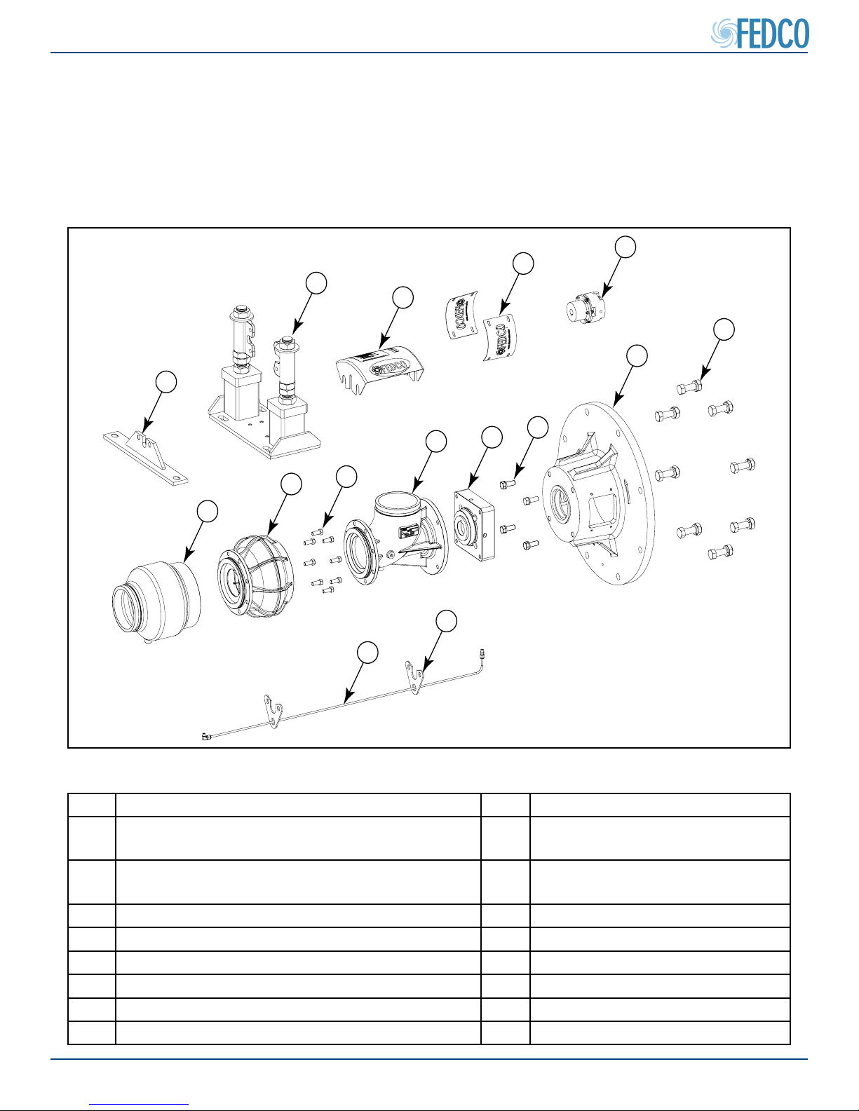
MSD External Components
Inspection of Unit Upon Receipt
• Review the contents of the packing list to make sure all components have been included.
• Inspect all components for signs of damage which may have occurred during shipping.
• If damage is present or if the contents are incomplete, please contact your shipping company
or a FEDCO representative before proceeding.
Figure 1 - Pump Assembly External Components
Item Description Item Description
1 Vertical leveling foot
(Vertical conguration)
2 Precision leveling foot
(horizontal orientation only)
9 Inlet housing
10 High pressure seal carrier
(Optional)
3 Branding plate 11 Inlet housing bolts
4 Coupling guards 12 Motor adapter
5 Flexible coupling 13 Motor adapter bolts
6 Discharge housing 14 Bearing drain line
7 Diuser housing (bowl) 15 Drain tube holder
8 Diuser housing bolts
© Copyright 2018 Fluid Equipment Development Company | www.fedco-usa.com
- 5 -
Unpacking/ Inspection/ and Storage Continued
MSDTM Series
Pump Storage Requirements
• The MSD unit must be protected from
moisture, sand, grit, and other foreign matter. Do not remove the protective covers
from the pipe connections until ready to install. For long-term storage, keep pump and
all other components in its original crate
away from moisture, sand or dust.
Long-Term Storage (>6 Months) Checklist
1. Check caps to ensure they have not been
damaged or allowed debris inside the unit.
• Check for debris (wood, slag, sand or any
dirt) and clean up with a clean, wet rag if
minor.
2. Shaft Check:
• Turn manually (through feed inlet) and
check for ease of turning.
• Check for axial movement.
3. Seal Check:
• Prime MSD with clean water and allow the
O-rings to soak for 1 hr before start-up.
Check for leaks.
Motor Storage Requirements
• Specic conditions are required for proper motor care and storage. Refer to the motor manufacturers instructions for specic steps and instructions.
Pre-Installation
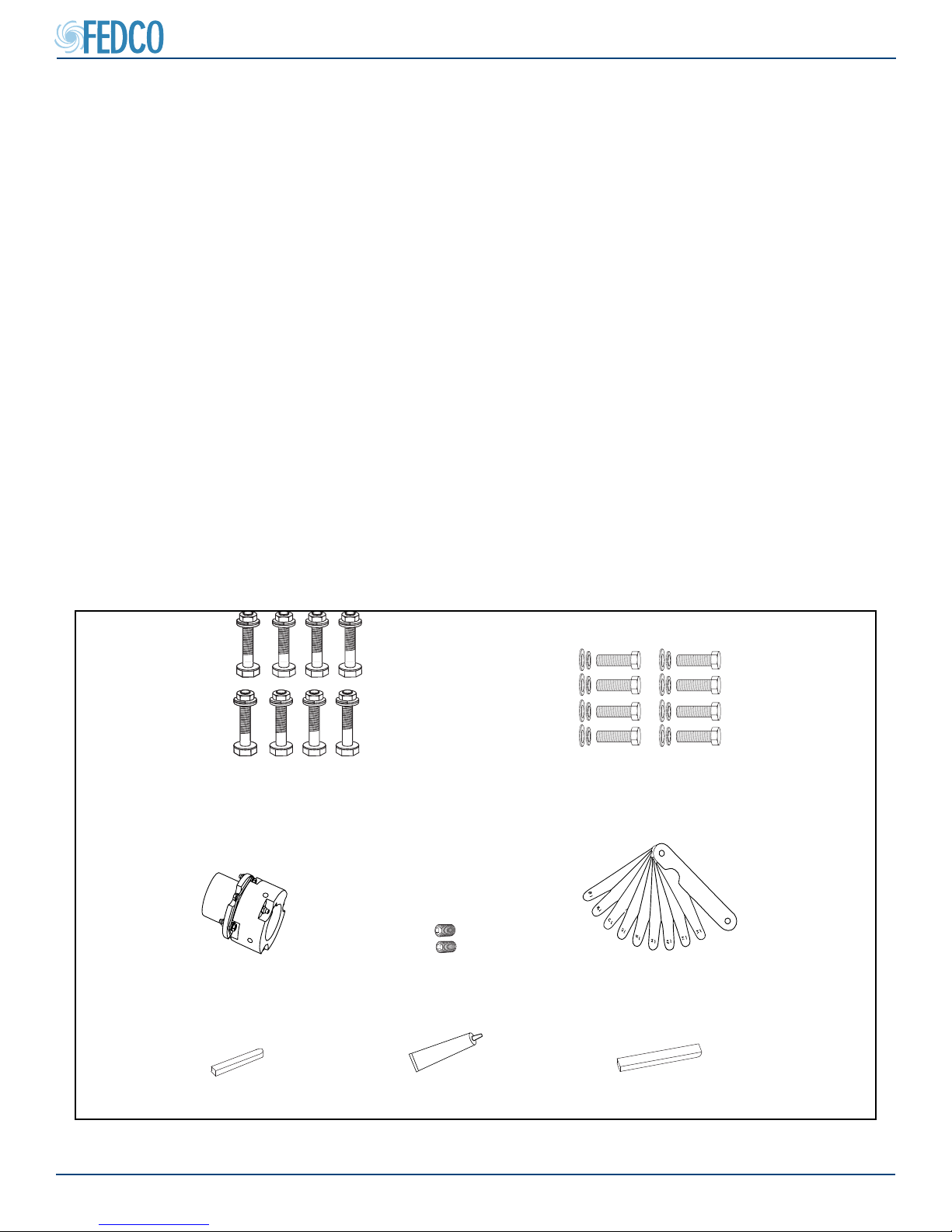
• In most instances, the unit and motor are shipped pre-assembled. All necessary installation
accessories will be included with the pump.
Motor mounting bolts with washers and nuts
(if motor and baseplate is provided by
FEDCO)
(note that quantities may vary, depending on pump size)
Coupling
Pump shaft key
© Copyright 2018 Fluid Equipment Development Company | www.fedco-usa.com
Motor adapter bolts with washers
(note that quantities may vary, depending on pump size)
Coupling set screws
ANTI-SEIZE
Anit-seize compound
(Horizontal orientation only)
Motor shaft key (if motor is
provided by FEDCO)
Figure 2 - Installation Accessories
- 6 -
Feeler Gauges
MSDTM Series
Theory and Operation
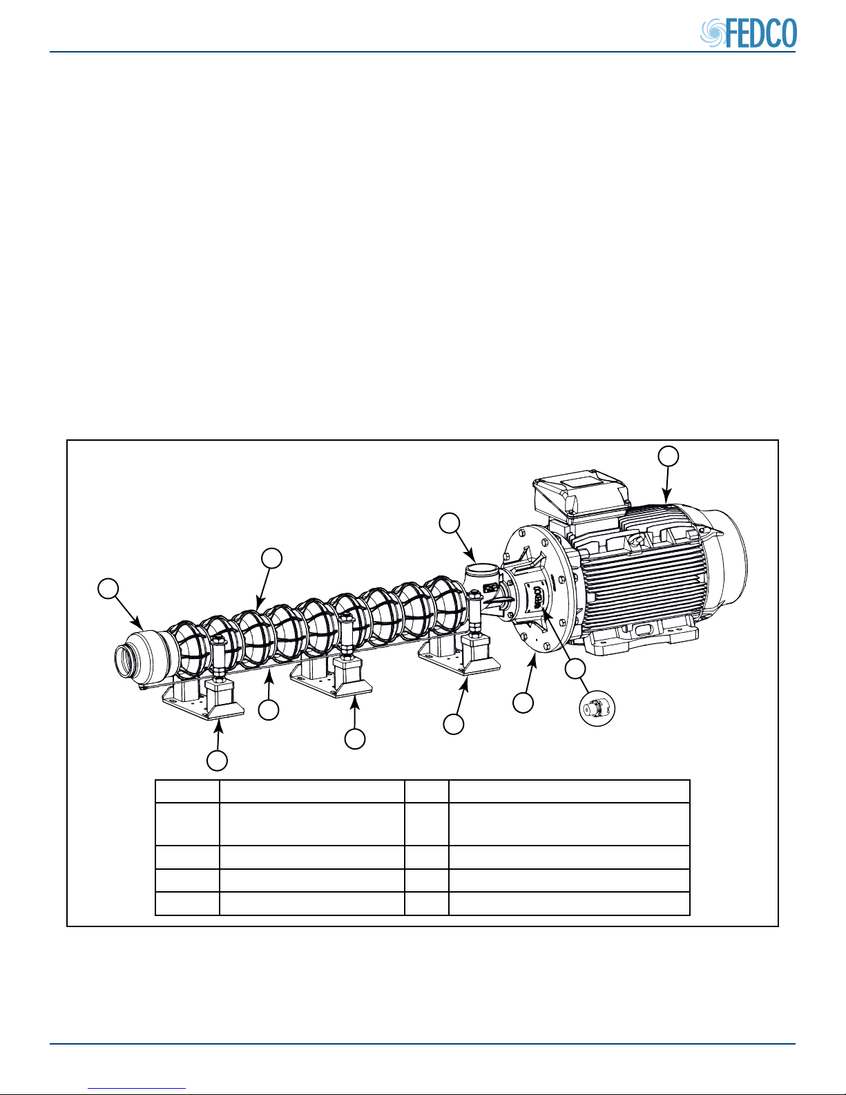
Technical Description
Multi-stage duplex (MSD) pumps are centrifugal
feed pumps designed for high pressure reverse
osmosis (RO) service. MSD pumps develop pressure by using a series of separate pump stages
bolted together and mounted around a rotating
shaft. Each stage contains an impeller which
rotates uid with centrifugal force developing a
pressure higher than the initial input. Pressure
can be increased through the addition of stages or by increasing shaft rpm. An optional high
pressure seal package is available for these
applications if pump inlet pressure exceeds
150 psi (10 bar).
Motors are selected according to equipment
operating requirements. A exible coupling allows the pump shaft to oat within the coupling
eliminating thrust against the motor. The inlet
and discharge housings are designed to connect to grooved rigid piping with couplings. The
inlet housing itself can be attached to the pump
in four dierent positions 90° apart. Precision
leveling feet support the pump stages along
its length. All precision leveling feet are fully
adjustable to allow accurate motor and shaft
alignment.
1
2
3
4
8
6
5
5
5
7
Item Description Item Description
1 Motor 5 Precision Leveling Foot
(Horizontal Conguration Only)
2 Inlet Housing 6 Bearing Drain Line
3 Diuser Housing (bowl) 7 Motor Adapter
4 Discharge Housing 8 Flexible Coupling
Figure 3 - MSD Pump External Components
© Copyright 2018 Fluid Equipment Development Company | www.fedco-usa.com
- 7 -

Theory and Operation Continued
MSD Pump Internal Components
MSDTM Series
The internal components of an MSD pump can
vary depending on pump conguration and
number of stages. Each stage uses a cen-
trifugal impeller with a spacer and wear ring to
reduce internal leakage.
The WATER BEARING™ assembly is located
at the discharge end of the pump. A balance
disc rotates in the bearing carrier and serves
as a thrust bearing for the pump. This unique
design uses patented WATER BEARING™
technology which allows feed water to cool and
lubricate the balance disc.
WATER BEARING™
ASSEMBLY
As the motor rotates the pump, pressure dierences acting on the rotating impellers generate
an axial thrust acting toward the motor. The
WATER BEARING™ employs the balance disc
to create a counter-pressure which exactly can-
cels the impeller thrust load. The bearing drain
line is used to produce the counter-pressure on
the balance disc. This thrust and counter-thrust
allows the disc to “self-balance” based on oper-
ating conditions.
INLET
SINGLE
PRESSURE
STAGE
DISCHARGE
PRESSURE
Figure 4 - MSD Pump Internal Flow
© Copyright 2018 Fluid Equipment Development Company | www.fedco-usa.com
- 8 -
MSDTM Series
Installation Procedures
Warnings and Safety Precautions
Safety practices and precautions for the operation and maintenance of all FEDCO pump products
MUST BE FOLLOWED. This information supple-
ments oral or written instructions that may be received. Safety MUST be practiced as part of the
standard operating procedures for this equipment
during any installation and operation. To ensure that
safe operating and maintenance procedures are followed, operators should develop and keep up a program of safety checks and current instructions. This
manual contains certain operating and maintenance
procedures that involve exposure to potentially hazardous situations. The levels of hazardous situations
are as follows:
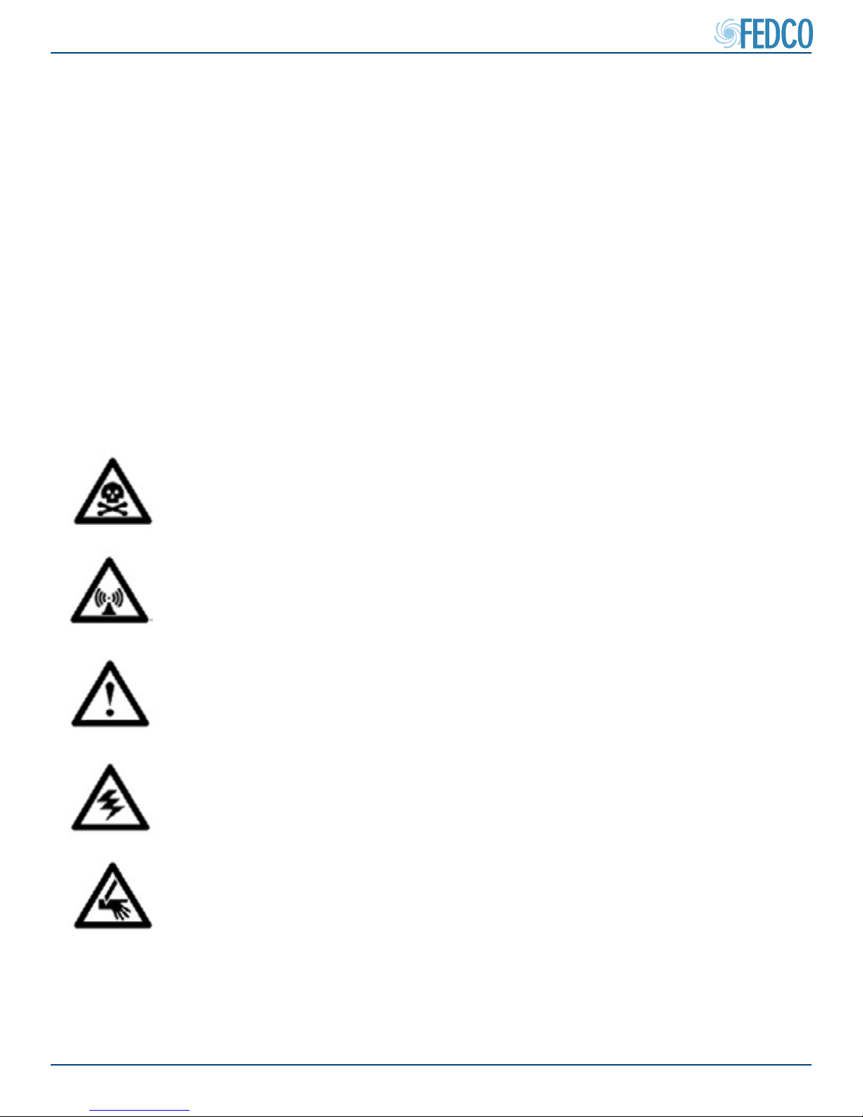
DANGER
WARNING
CAUTION
ELECTRICAL
HAZARD
PUNCTURE
HAZARD
Hazards which are IMMEDIATELY ACCESSIBLE, and capable of
causing SEVERE PERSONAL INJURY OR DEATH.
Hazards which are NOT IMMEDIATELY ACCESSIBLE, but are
capable of causing SEVERE PERSONAL INJURY OR DEATH.
Hazards which are NOT IMMEDIATELY ACCESSIBLE, and can
cause PERSONAL INJURY.
Hazards which are related to Electrical Components and can
RESULT IN ELECTRICAL RISKS, SHOCK, ELECTROCUTION
OR DEATH if instructions are not followed properly.
Hazards which are NOT IMMEDIATELY ACCESSIBLE and can
RESULT IN SEVERE PERSONAL INJURY OR DEATH if instructions are not followed properly.
© Copyright 2018 Fluid Equipment Development Company | www.fedco-usa.com
- 9 -
MSDTM Series
Installation Procedures Continued
WARNING
All pump and safety precautions must be followed
to prevent physical injury to the operator. It is illegal
to operate the equipment in an EU member state if
the manual(s) is not written in that states language.
Contact FEDCO if a translated copy is needed.
CAUTION
A pump is a pressure-generating device with rotating
parts that can be hazardous. Any device containing
generated pressure can rupture, explode or discharge its contents if it is over-pressurized and may
possibly result in personal injury, property damage,
environmental damage and death. All necessary
precautions must be exercised to insure over-pressurization does not occur. FEDCO will not accept
responsibility for physical injury, damage or delays
caused by a failure to observe the instructions in this
manual.
WARNING
Installation, operation or maintenance of the pump
unit in any manner which is not covered in this
manual could cause damage to the equipment, seri-
ous injury or death. This includes any modication
to the equipment or the use of parts not provided by
FEDCO. If there is a question regarding the intended use of the equipment, please contact a FEDCO
representative before proceeding.
CAUTION
This manual clearly identies accepted methods for
safe disassembly and assembly. These methods
must be strictly adhered to.
WARNING
Do not use the pump equipment for a dierent application than originally specied without the approval
of a FEDCO representative.
WARNING
NEVER operate the pump equipment:
● below the minimum ow rate.
● when dry.
● without priming.
● without proper guards and safety devices installed.
● with the discharge valve closed.
● with the suction valve closed.
WARNING
FEDCO pumps are intended to pump saltwater
and brine to membranes for the reverse osmosis desalination process. FEDCO pumps are not
intended to pump ammable or hazardous liquids.
Solutions intended for human consumption need
proper purication per product. FEDCO approval
will be needed to control slurry and particle size
for this specic product
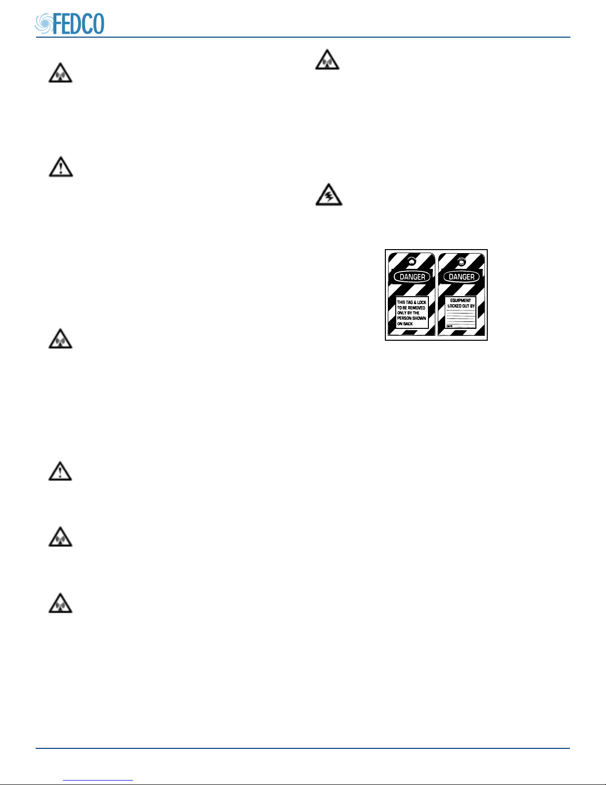
ELECTRICAL HAZARD
Always follow the Lock-out / Tag-out procedure
developed by your company before starting any
maintenance or repair.
Figure 5 - Typical Lock-Out Tag-Out Tag
User Health and Safety
Safety equipment and PPE (Personal Protection
Equipment) should be used in accordance with
company regulations.
In the Work Area
• Always keep the work area clean and dry.
• Avoid all electrical dangers. Be aware of risks
from electric shock or arc ash hazards.
• Utilize adequate lifting equipment and
methods.
Electrical Connections and Regulations
• Refer to the motor nameplate for specic
electrical operating information.
• Electrical connections must be made by
certied electricians in compliance with
all international, national, state, and local
regulations and codes.
• Insure the product is isolated from the power
supply and cannot be accidentally energized.
• Make sure all thermal contacts are connected
to a protection circuit according to product
specications.
• All electrical equipment must be properly
grounded.
• During installation, service and repair, the
companies Lock out / Tag out Procedure must
be followed.
© Copyright 2018 Fluid Equipment Development Company | www.fedco-usa.com
- 10 -
MSDTM Series
A
C SINE WAVE
POWER
VFD
VARIABLE
FREQUENCY
POWER
OPERATOR
CONTROLS
6.13752
®
A
A
Installation Procedures Continued
GIANT
INDUSTRIAL MOTOR
CAT. NO.
VM3559
SPEC.
35A13T123
3
HP
208-230/460
VOLTS
8.1-7.6/3.8
AMPS
R.P.M.
3450
56C HZ 60 PH 3
FRAME
1.15CODEK
SER. F.
NEMA NOM. EFF.
RATING
CC
BEARINGS
ENCL.
82.5%P. F. 89 %
40C AMB-CONT
USABLE AT 208V
DE 6205
TEFCSN FO603113416
MFG. BY BALFOR ELECTRIC CO. U.S.
NP1256L
DES
ODE6203
BCLASS
8.1
F
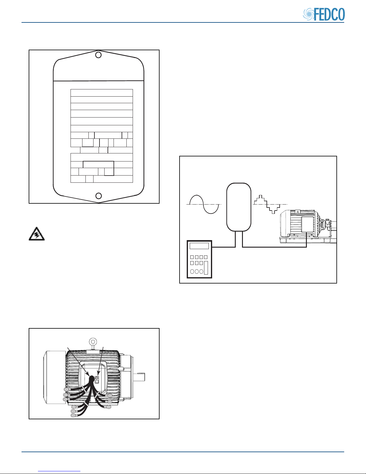
Variable Frequency Drive (VFD) Requirements
A VFD must be used to optimize the system to
the best eciency point (BEP) of the RO system.
The VFD must be congured to match the motor
nameplate information. The VFD does not come
pre-programed. Please contact the equipment
supplier if the VFD programming manual is not
available. Important note for CE compliant countries: the VFD must have a line lter which must
be installed in the same metallic enclosure as the
drive.
Figure 6 - Typical Motor Nameplate
Motor Requirements
Wiring of the motor shall be completed
in conformance with all local electrical
codes. All EU countries must follow EN
60204-1. If a variable frequency drive
(VFD) is provided with the motor, it is
recommended that shielded cables are
used between the VFD and the motor.
The shield must be connected at both
ends.
ELECTRICAL HAZARD
3-PHASE
MOTOR
PIGTAILS
GROUNDING
LUG
Figure 8 - Basic VFD Conguration
Motor and Pump Installation Requirements
A rigid mounting surface is required for pump-
motor assemblies in order to prolong the life of
critical components. Mounting surfaces constructed of wood or other non-rigid materials are
NOT acceptable as they may deect during pump
operation and cause shaft misalignment. All
anchoring fasteners used should meet or exceed
manufacturers specications. All assemblies must
be mounted on one of three types of substrates:
• concrete foundation.
• optional baseplate.
• container with a suitable steel substructure.
Figure 7 - Typical Motor Electrical
Connections
© Copyright 2018 Fluid Equipment Development Company | www.fedco-usa.com
- 11 -
MSDTM Series
Installation Procedures Continued
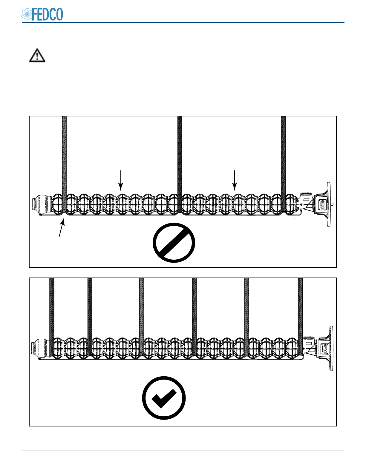
Horizontal Lifting and Handling
CAUTION
Observe all lifting precautions. Failure to follow all lifting and handling precautions may result
in serious injury! Unit weight is listed on the unit nameplate. Mechanical lifting equipment must
be used. MSD pumps can be lifted using approved lifting straps and suitable lifting equipment. The
straps must be installed every four (4) stages without disturbing the drain line. If straps are
placed around the drain line,or if an insucient number of lifting straps are used, damage will oc-
cur.
EXCESSIVE LOADEXCESSIVE LOAD
BENT DRAIN
LINE
NO
Figure 9 - Improper Lifting Strap Positioning
4 STAGE SPAN MAXIMUM
YES
Figure 10 - Proper Lifting Strap Positioning
© Copyright 2018 Fluid Equipment Development Company | www.fedco-usa.com
- 12 -

MSDTM Series
NO
Installation Procedures Continued
Horizontal Lifting And Handling Continued
CAUTION
Whenever possible, all components should be lifted and moved separately for safety. Do not lift
the pump up by the shaft. If the unit is lifted by the shaft, damage may occur. Lifting and handling
of the motor must be performed according manufacturers instructions. Do not lift the pump and
motor by the motor eyebolt. The eyebolt is used for lifting the motor only.
NOTES: Do not lift pump and base plate with the motor on the base plate. The pump and base
plate need to be installed and then the motor installed.
NOTES: The motor and base plate need to be lifted from a combination of lifting points so the
pump and base plates total weight is balanced.
Motor and Pump Assembly Lifting
Figure 11 - Improper Lifting Points Horizontal
Figure 13 - Proper Motor and Pump Lifting (Both Sides of Base Plate)
© Copyright 2018 Fluid Equipment Development Company | www.fedco-usa.com
Figure 12 -
LIFT POINTS
- 13 -
MSDTM Series
Installation Procedures Continued
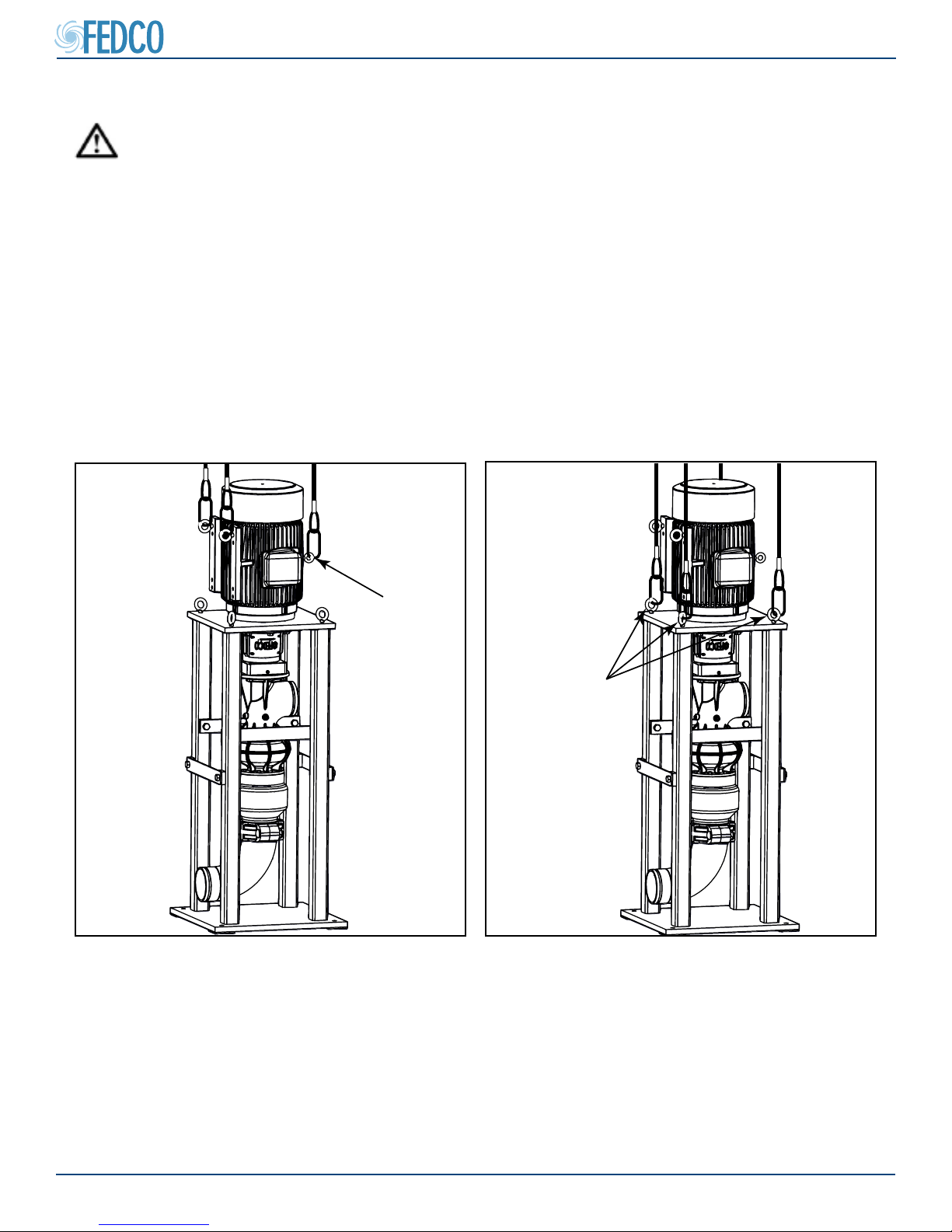
Vertical Lifting And Handling
CAUTION
Observe all lifting precautions. Failure to follow all lifting and handling precautions may result in
serious injury! Unit weight is listed on the unit nameplate. Mechanical lifting equipment must be
used. MSD pumps can be lifted using approved lifting straps and suitable lifting equipment.
Whenever possible, all components should be lifted and moved separately for safety. Do not lift
the pump up by the shaft. If the unit is lifted by the shaft, damage may occur. Lifting and handling
of the motor must be performed according manufacturers instructions. Do not lift the pump and
motor by the motor eyebolts. The eyebolts are used for lifting the motor only.
NOTES: The motor and base plate need to be lifted from a combination of lifting points so the
pump and base plates total weight is balanced.
Motor and Pump Assembly Lifting
NO
Figure 14 - Improper Lifting Points Vertical
LIFT POINTS
(4X)
Figure 15 - Proper Motor and Pump Lifting
© Copyright 2018 Fluid Equipment Development Company | www.fedco-usa.com
- 14 -
MSDTM Series
Installation Procedures Continued
Optional Horizontal Baseplate Installation
Some units include an optional FEDCO baseplate which provides good mounting surfaces for the
motor and pump. It also increases accuracy during the alignment process. Although the base-
plate is precisely manufactured, it requires a solid foundation such as a concrete pad or rigid
steel substructure. If the optional baseplate is used, it must be installed rst to avoid distortion
which may occur due to uneven oors or substructure. If the pump is installed within a container,
it must be mounted on a rigid steel substructure that will not distort under the weight of the equip-
ment or from torque reaction forces during pump operation.
1
5
2
4
2
3
1
2
5
Item Description Item Description
1 Motor mounting (4 to 6 depending on motor) 4 Precision leveling foot mounting plate
2 Lateral jacking plates 5 Baseplate mounting feet
3 In-line jacking plate
Figure 16 - Optional Horizontal Baseplate
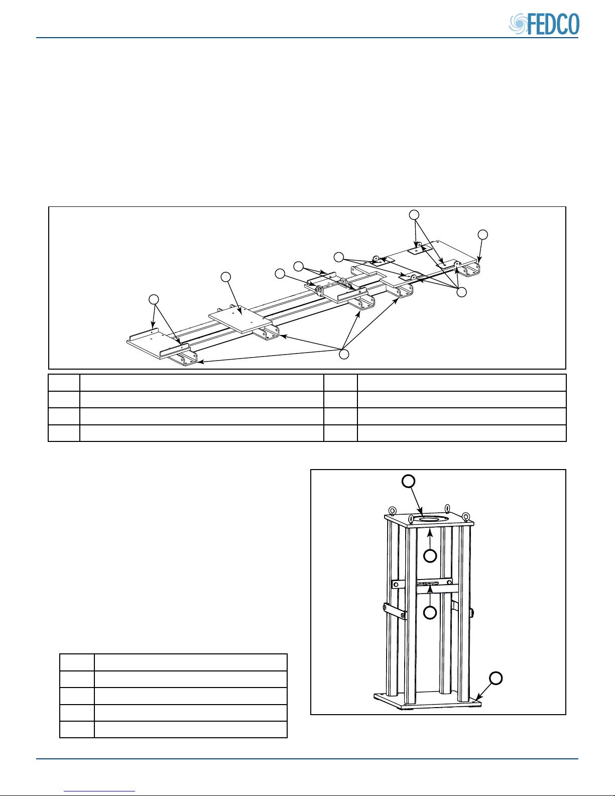
Optional Vertical Baseplate Installation
1
Some units include an optional FEDCO baseplate which provides good mounting surfaces
for the motor and pump. It also increases accuracy during the alignment process. Although the
baseplate is precisely manufactured, it requires
2
a solid foundation such as a concrete pad or
rigid steel substructure. If the optional baseplate
is used, it must be installed rst to avoid distor-
3
tion which may occur due to uneven oors or
substructure.
Item Description
1 Motor mounting
2 Motor adapter mounting
3 Vertical support brace
4 Baseplate mounting pad
© Copyright 2018 Fluid Equipment Development Company | www.fedco-usa.com
4
Figure 17 - Optional Vertical Baseplate
- 15 -
Installation Procedures Continued
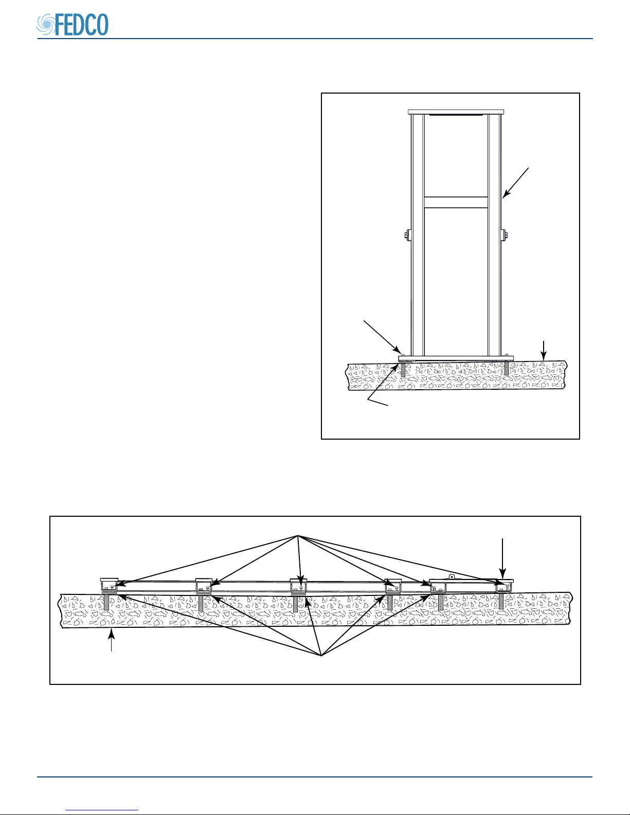
Foundation Specications
A concrete foundation is recommended for
all MSD pump installations. Concrete provides
good support and good vibration absorption.
The foundation should have a mass that is
50% more than the total weight of the equipment and its perimeter should extend at least
6 inches (15 cm) on each side from the pump
and motor. Make sure the concrete is com-
pletely dry and level before installing any machinery. Make sure anchor bolts and shims are
properly sized and installed in cases of uneven
surfaces.
MSDTM Series
VERTICAL
BASEPLATE
LEVELING BOLTS
CONCRETE
FOUNDATION
CONCRETE FOUNDATION
(Shims are optional with alignment kit. Anchor bolts are not provided)
Figure 19 - Proper Shimming Uneven (Horizontal)
(Shims are optional with alignment kit. Anchor bolts are not provided)
Figure 18 - Proper Shimming Uneven (Vertical)
LEVELING BOLTS
PROPER SHIM PLACEMENT
PROPER SHIM PLACEMENT
OPTIONAL BASEPLATE
© Copyright 2018 Fluid Equipment Development Company | www.fedco-usa.com
- 16 -
MSDTM Series
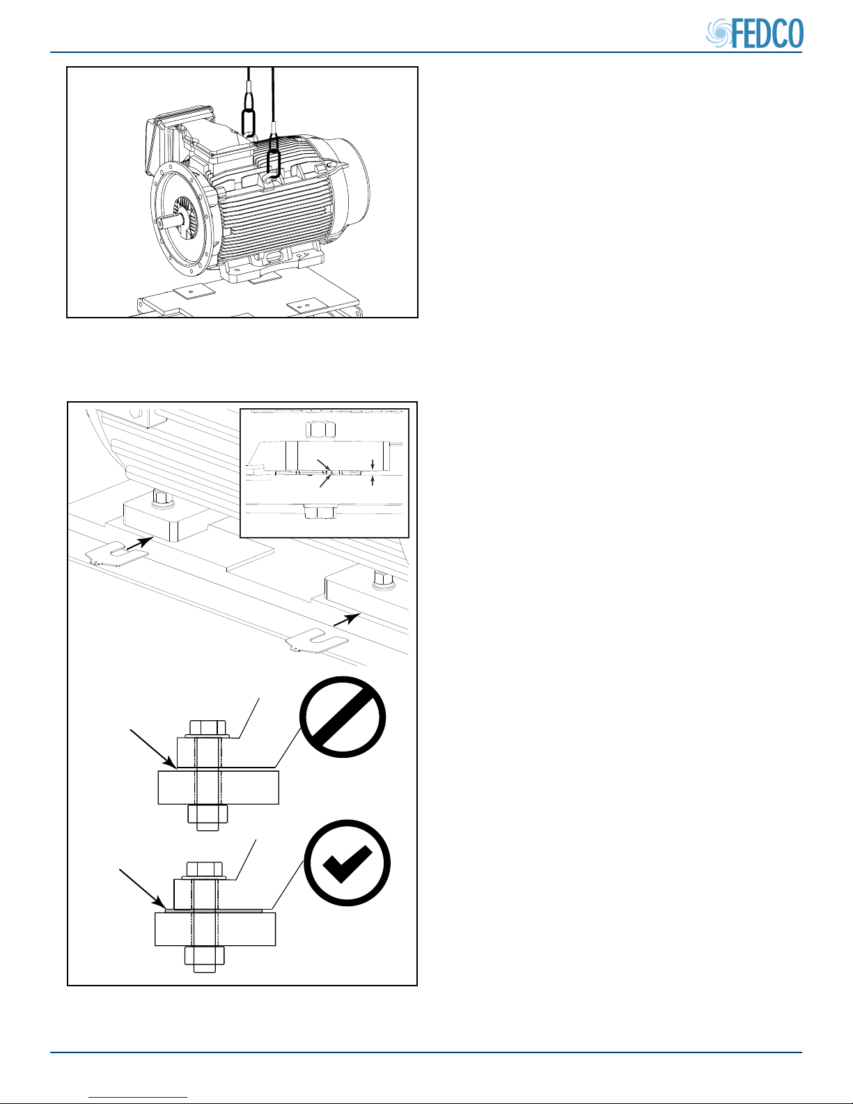
Figure 20 - Placing Horizontal Motor In
Mounting Position
Pump Assembly
Horizontal Motor Installation
1. Clean the motor ange face with a clean
cloth to remove any foreign matter, rust or
protective coating and place the motor in its
mounting position
2. Install the motor mounting bolts and shims
as necessary. Tighten to motor manufactur-
ers specications.
SOFT-FOOT
PROPERLY
SHIMMED
NOTES: Make sure to install shims where
necessary to prevent motor frame distortion re-
sulting from “soft-foot.” Soft-foot is a condition
were one of the motor frame feet are not in at
contact with the mounting base. If not properly
shimmed when the bolt is tightened, the motor
frame will distort. FEDCO does not supply motor shims.
NO
Figure 21 - Install Motor Mounting Shims
© Copyright 2018 Fluid Equipment Development Company | www.fedco-usa.com
YES
- 17 -
Pump Assembly Continued
3. Prior to pump installation energize the motor
to determine the direction of motor rotation.
The correct rotation is indicated by arrows
on the motor adapter. If the rotation is incorrect, reverse the polarity of motor wiring to
change the direction of rotation.
NOTES: Reversing polarity of the VFD power
input wires will not change the motor rotational
direction.
4. If the motor rotational direction is correct,
disconnect power to the motor according to
lock-out/tag-out procedures and complete
all electrical connections according to local
codes and regulations.
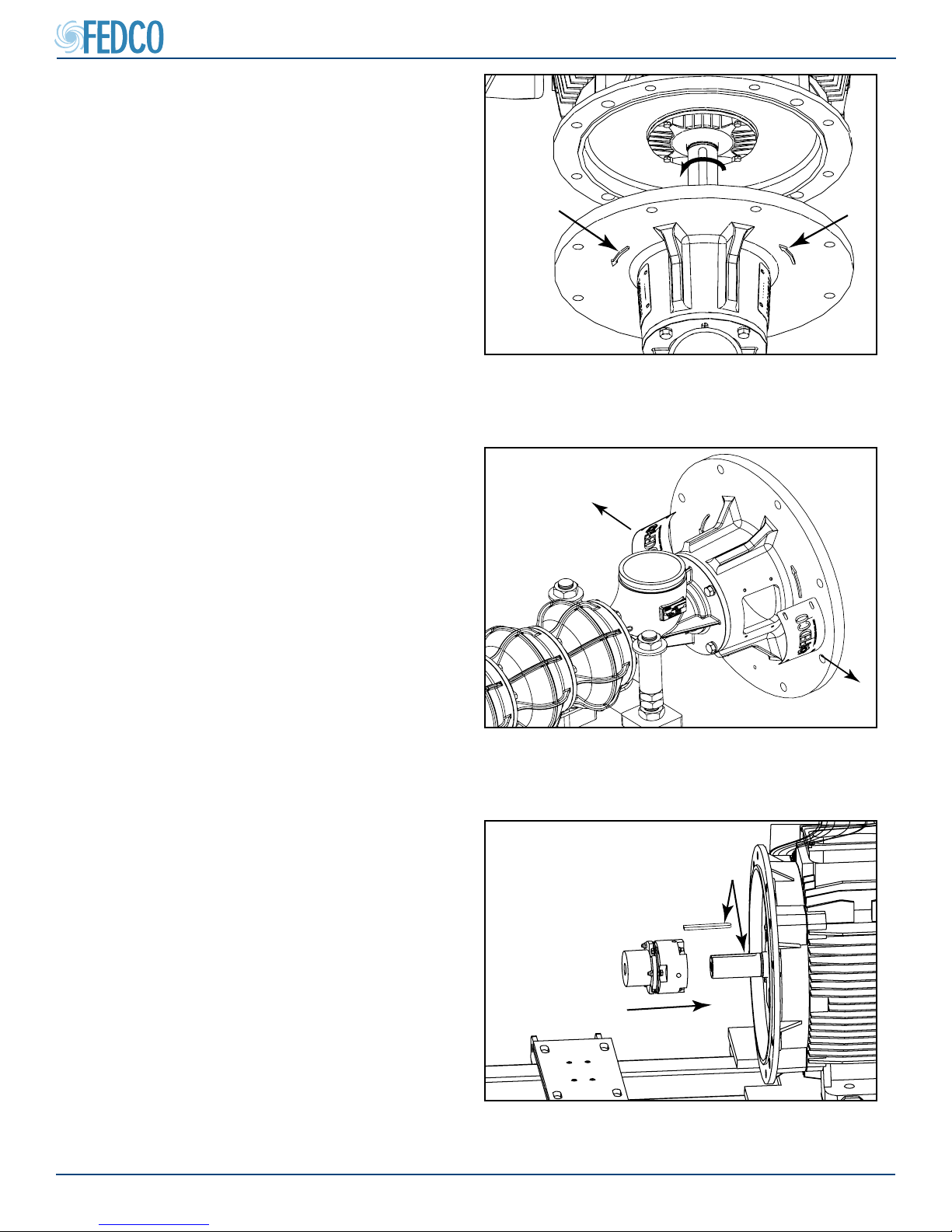
5. Loosen screws and remove the two coupling
guards. This allows better access to view
the coupling alignment in later steps.
MSDTM Series
Figure 22 - Direction Arrows On Motor Adapter
Flexible Coupling Check
6. Apply a system compliant anti-seize compound to the motor shaft keyway and install
the motor shaft key and coupling.
NOTES: If the motor shaft key does not t
properly in the coupling keyway, lightly le the
motor shaft key until a proper t is obtained.
© Copyright 2018 Fluid Equipment Development Company | www.fedco-usa.com
Figure 23 - Coupling Guard Removal
APPLY SYSTEM COMPLIANT
ANTI-SEIZE COMPOUND
Figure 24 - Install Flex Coupling On Motor
Shaft
- 18 -
MSDTM Series
NO
MOVEMENT
NO
MOVEMENT
NO
MOVEMENT
NO
MOVEMENT
SMOOTH MOVEMENT
Pump Assembly Continued
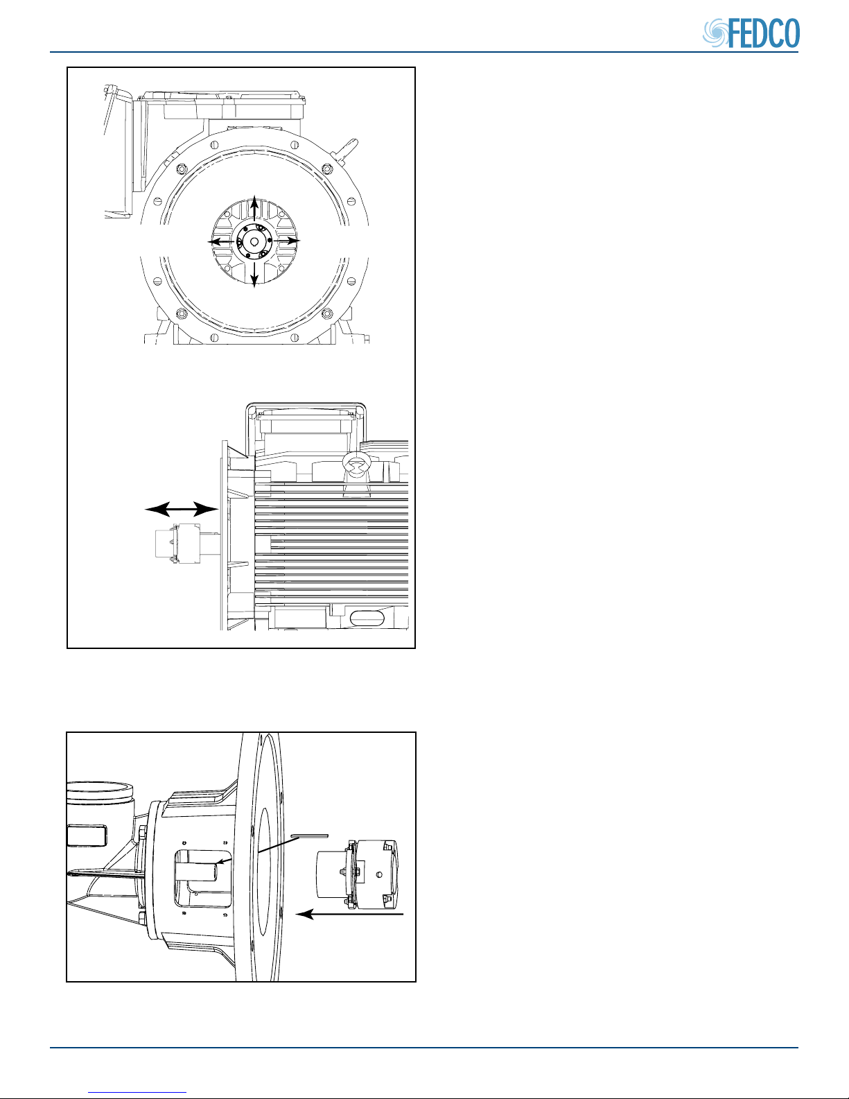
7. Inspect the exible coupling radial and axial
t. It should be tight with no visible radial
movement and slide smoothly on and o
the motor shaft
Figure 25 - Check Flex Coupling Fit On Shaft
Figure 26 - Installing Flex Coupling
8. Slide the exible coupling over the pump
shaft with the pump shaft key.
NOTES: The rounded end of the key must be
placed in the rounded end of the keyway.
© Copyright 2018 Fluid Equipment Development Company | www.fedco-usa.com
- 19 -
Pump Assembly Continued
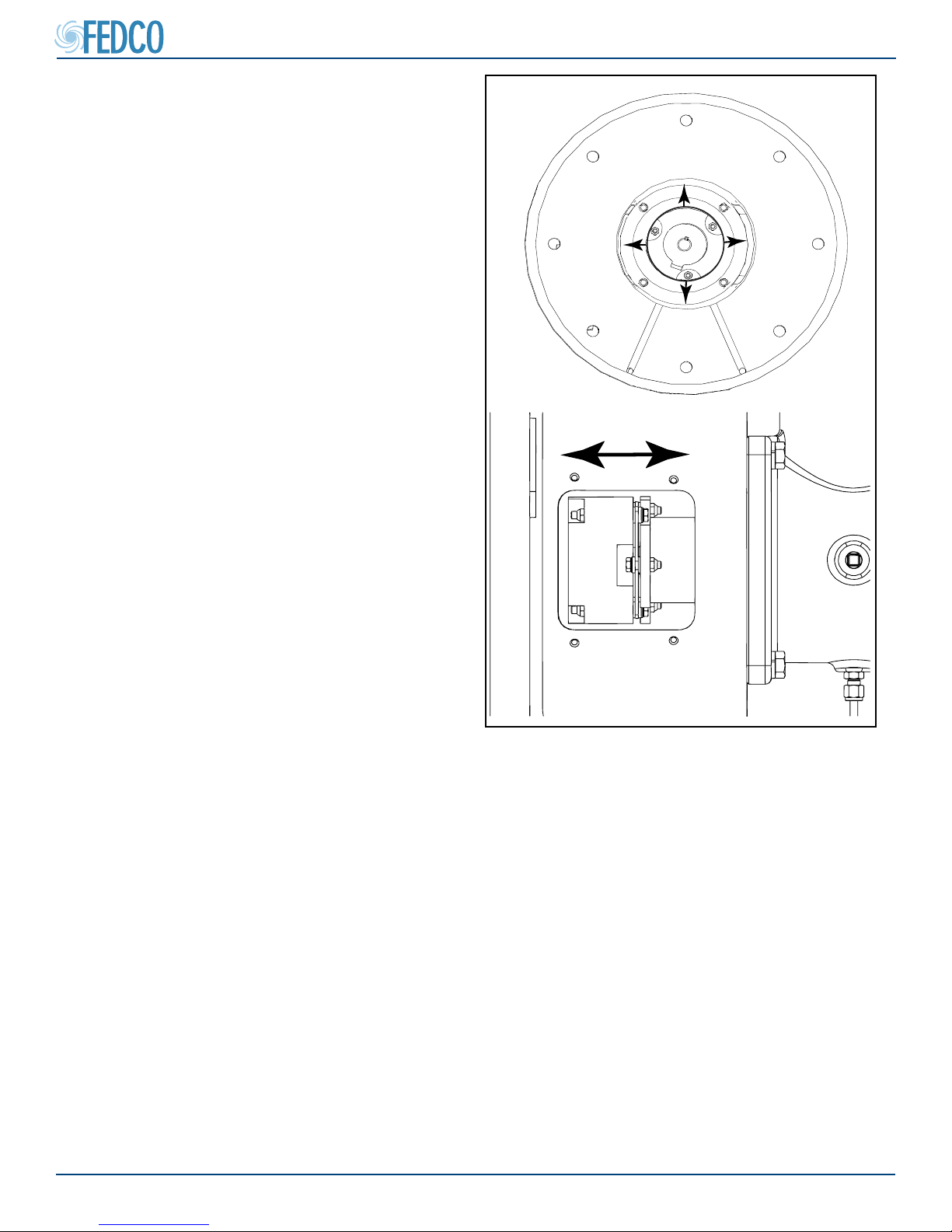
SMOOTH MOVEMENT
9. Inspect the exible coupling radial and axial
t. It should have little or no movement and
be slightly more loose than the motor shaft
t. It should also slide smoothly on and o
the pump shaft.
10. Once proper exible coupling t on both
shafts has been obtained, remove the exible coupling and proceed with Initial Pump
Alignment.
NOTES: The exible coupling will not be need-
ed until the Final Pump Alignment procedure.
LITTLE OR
NO MOVEMENT
MSDTM Series
LITTLE OR
NO MOVEMENT
LITTLE OR
NO MOVEMENT
LITTLE OR
NO MOVEMENT
© Copyright 2018 Fluid Equipment Development Company | www.fedco-usa.com
Figure 27 - Check Flex Coupling Fit
- 20 -
 Loading...