

Page 1
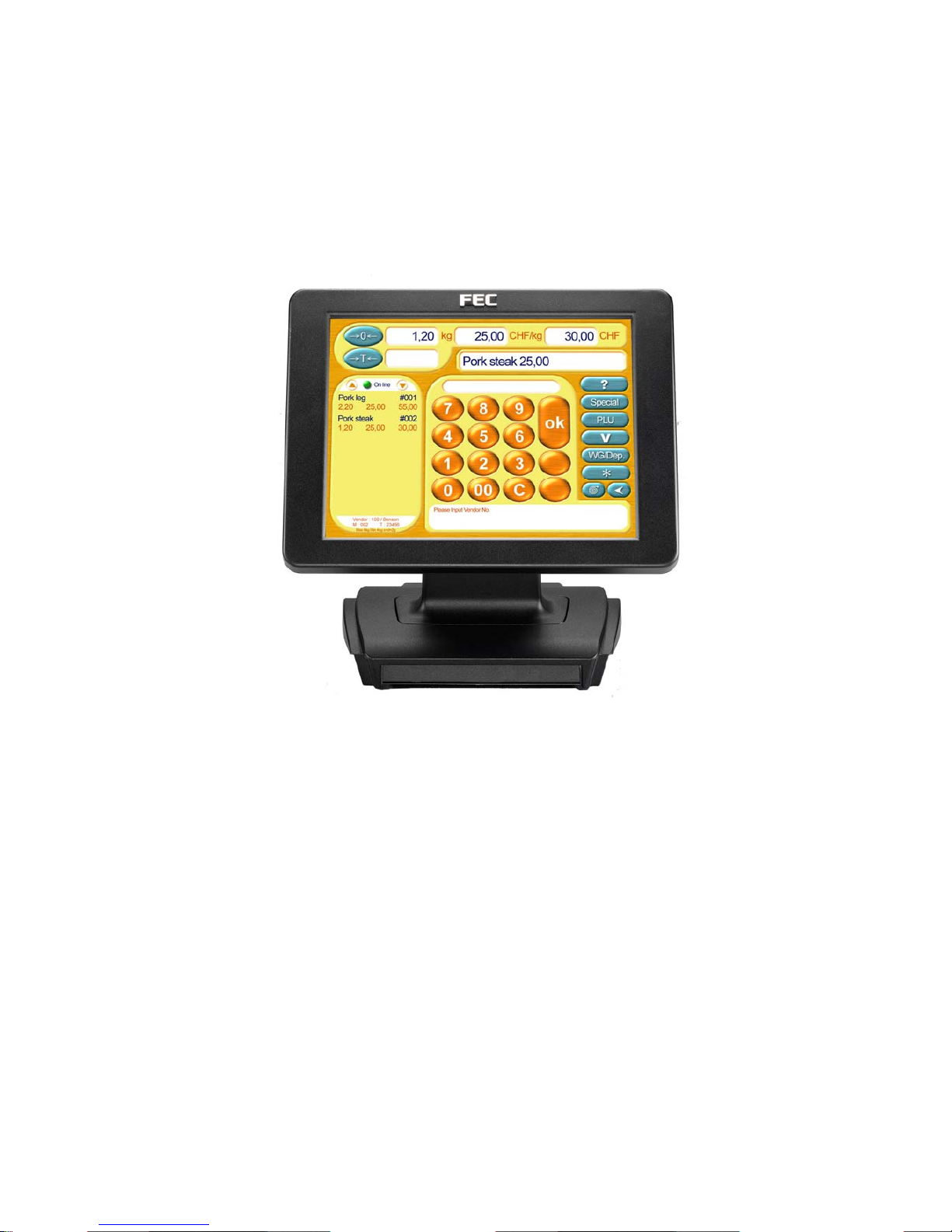
USB Aegis
Series
Page 2

USB Aegis – Series
`1
Table of Content
Features ...................................................................................... 3
Specifications ............................................................................. 4
Dimensional Diagrams............................................................... 5
Exploded View Diagram............................................................. 6
What is provided with the USB Aegis....................................... 7
Switch and Controls................................................................... 8
OSD Settings............................................................................... 9
USB-to Serial Driver Installation ............................................. 14
ELO Touch Tools Installation.................................................. 15
I/O Board Configuration........................................................... 22
Hardware Installation ............................................................... 27
External Power Adapter (optional).......................................... 29
MCR Installation ....................................................................... 30
MCR Parameter Modification................................................... 34
VFD Customer Display Installation ......................................... 36
Trouble Shooting...................................................................... 41
Page 3

USB Aegis – Series
`2
The information in this document is subject to change without prior notice in
order to improve reliability, design and function and does not represent a
commitment on the part of the manufacturer. In no event will the manufacturer
be liable for direct, indirect, special, incidental, or consequential damages
arising out of the use or inability to use the product or documentation, even if
advised of the possibility of such damages.
Note, any trade names, symbols, marks, icons and grammatical extracts contained within this
document are acknowledged as the property of their respective owners.
Page 4

USB Aegis – Series
`3
Features
¾ Cast aluminium front and base construction - rugged and durable
¾ Compact size and small footprint - fits where space is at a premium
¾ Standard VGA for easy interface to a standard PC VGA port.
(1) Wireless Wi-Fi LAN 802.11b (optional)
(2) USB upstream port for connection to host PC.
1x Powered USB (+12V) downstream port
1x USB 2.0 downstream port
1x USB to RS232 port
¾ Flicker-free LCD display - easy on the eyes
¾ Low radiation - poses less hazard to user’s health
¾ Power-thrift - environmentally friendly
¾ Tiltable display - adapts to placement, user position and lighting
conditions
¾ VESA mounting holes - fits optional tilt/swivel wall mount fixtures
¾ Flexible power options - tap power from the computer or use an
external adapter
¾ Point of sales industry specific options - touch screen, VFD customer
display, magnetic card reader
Page 5
USB Aegis – Series
`4
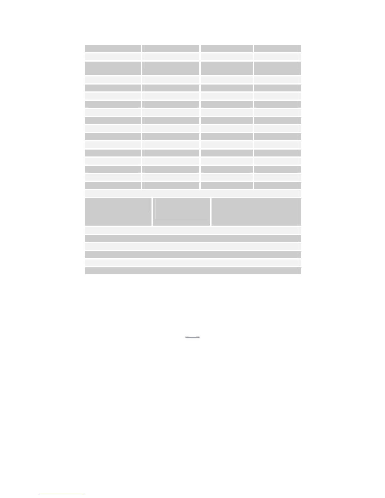
Specifications
Model U152TA U121TA U122TA
Display Panel
Type
TFT LCD TFT LCD TFT LCD
Display Area 15.00” 12.1” 12.1”
Display Resolution 1024 x 768 XGA 800X600 800X600
Colour Resolution 262,144 16.7M 16.7M
Pixel Pitch 0.297x 0.297 0.306X0.306 0.306X0.306
Brightness 350 nits (typ) 150 nits (typ) 300 nits (typ)
Contrast Radio 400:1 (typ) 150:1 (typ) 200:1 (typ)
Response time 16ms 40ms 20ms
Interfaces
cables & connectors
Standard VGA for
use with a Video
Graphic Adapter
Model specific options:PS/2 for MCR & 32 Keyboard,
RS232 for touch screen, DC
power.
Energy Saving Mode VESA DPMS compliant
Power Supply U152TA=12v @ 4A and U12xTA=12v @2A
Weight U152TA=6.4 kg and U12xTA= 5.5 Kg
Please note that the “x” denotes model specific options, e.g. U121TA standard
brightness and U122TA is high brightness.
The “T” means with Touch Screen, and the “A” stands for Analog.
For Model U12xTA, it is recommended to use 800X600 @ 60Hz for display
adapter settings. For Model U152TA, it is recommended to use 1024x768 @
60-75Hz for display adapter settings. Other resolutions would function, but
possibly at degraded display quality.
Page 6
USB Aegis – Series
`5
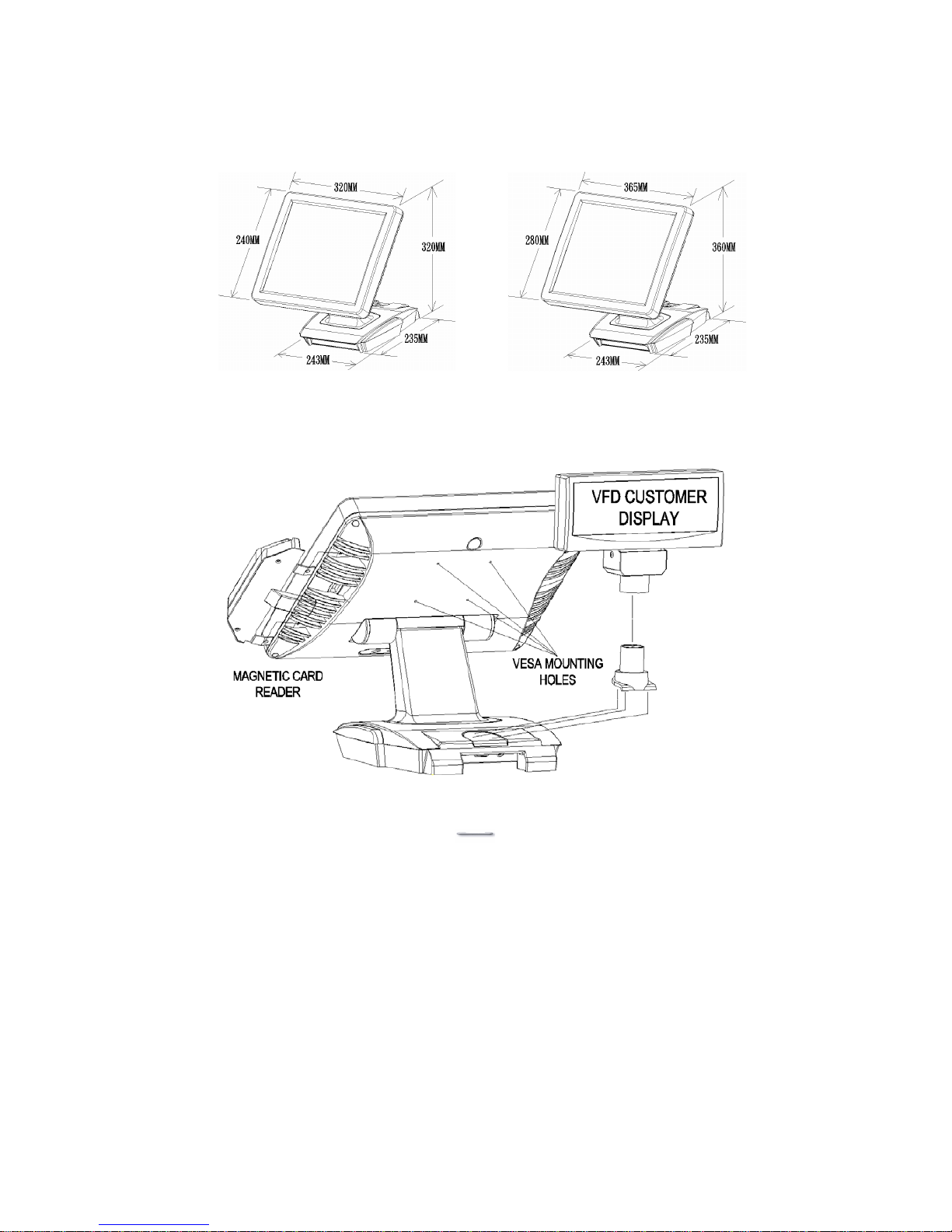
Dimensional Diagrams
U152TAU12xTA
Page 7
USB Aegis – Series
`6
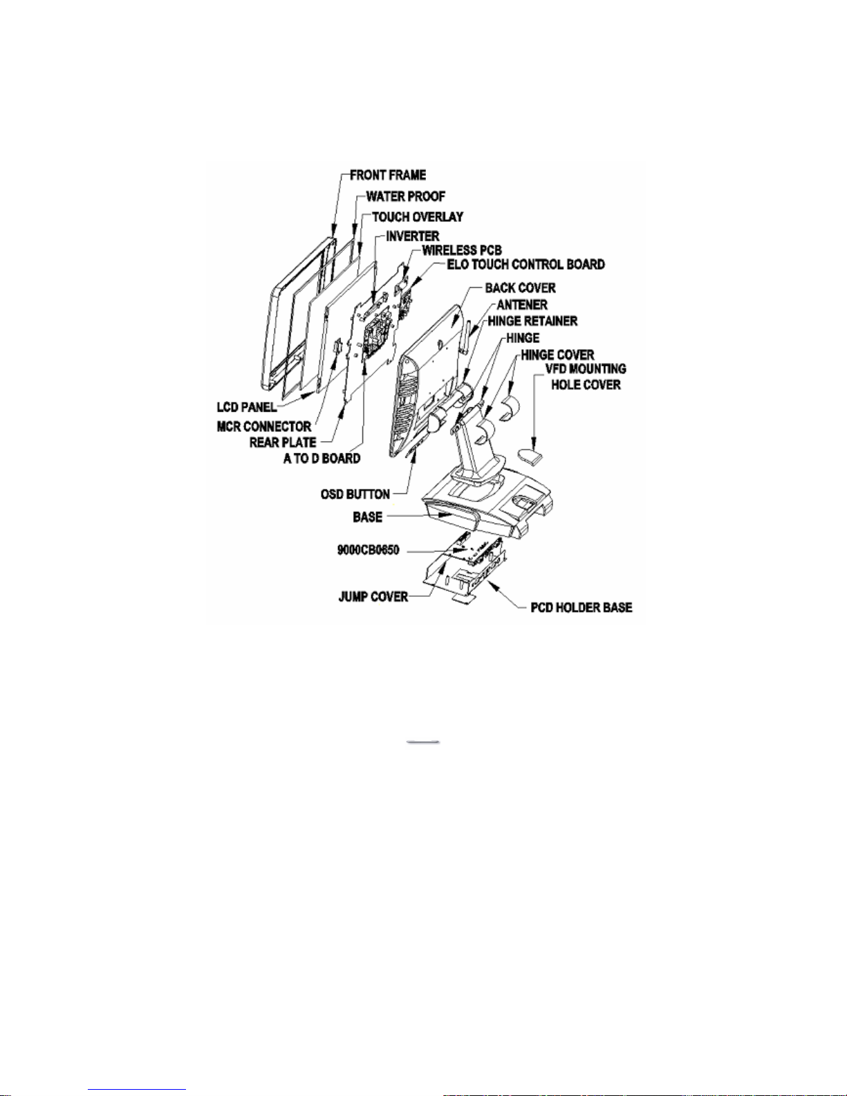
Exploded View Diagram
Page 8
USB Aegis – Series
`7
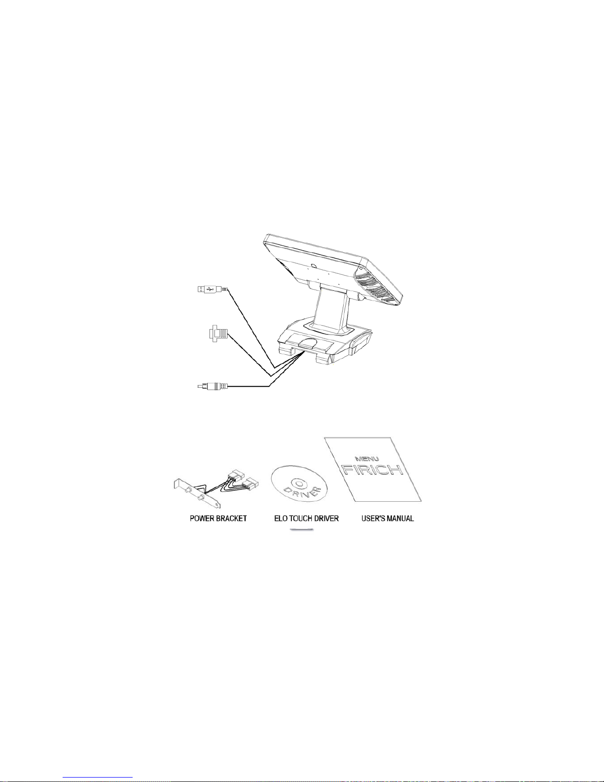
What is provided with the USB Aegis
Upon unpacking, please inspect to make sure all items are in place and in
good condition. If there is any damaged or missing item, please contact your
dealer immediately.
The following items come as standard
1. LCD Display unit with tilt base
2. Power bracket 9000XC1694
3. DC power cable 9000XC1718
4. USB Cable 9000XC1607
5. VGA Cable 9000XC1693
6. User’s manual
7. Driver CD for ELO touch screen
USB Aegis
Page 9
USB Aegis – Series
`8
Switch and Controls
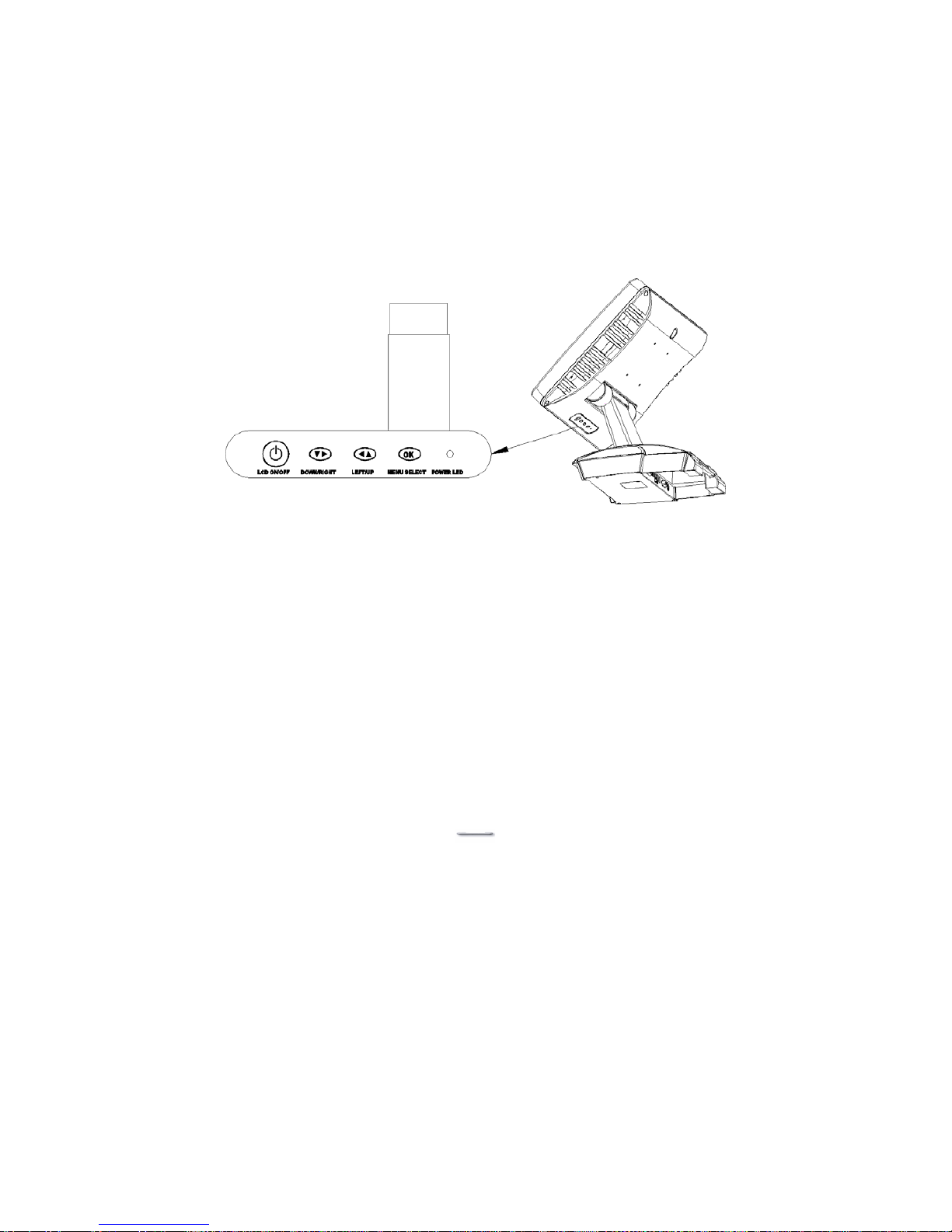
Model U152TA / U12xTA has built-in OSD (on screen display) controls to
adjust various display parameters. The control buttons are located on the
bottom of the back cover.
Page 10

USB Aegis – Series
`9
OSD Settings
There are four buttons on OSD panel: Menu / Enter, Right, Left and LCD
ON/OFF. The functions of these four buttons are as follows
Menu/Enter Button
Press it to open OSD window and enter user mode to do the function
adjustment or selection of the item. It may have many levels in one
item. As you select this kind of item, you will enter the next level and
see the sub-items.
Right Button
Press it to Scroll item Right or to decrease the value or to switch the
selected item to another.
.
Left Button
Press it to Scroll item Left or to increase the value or to switch the
selected item to another.
).
LCD ON/OFF Button
Control LCD ON/OFF button
Page 11
USB Aegis – Series
`10
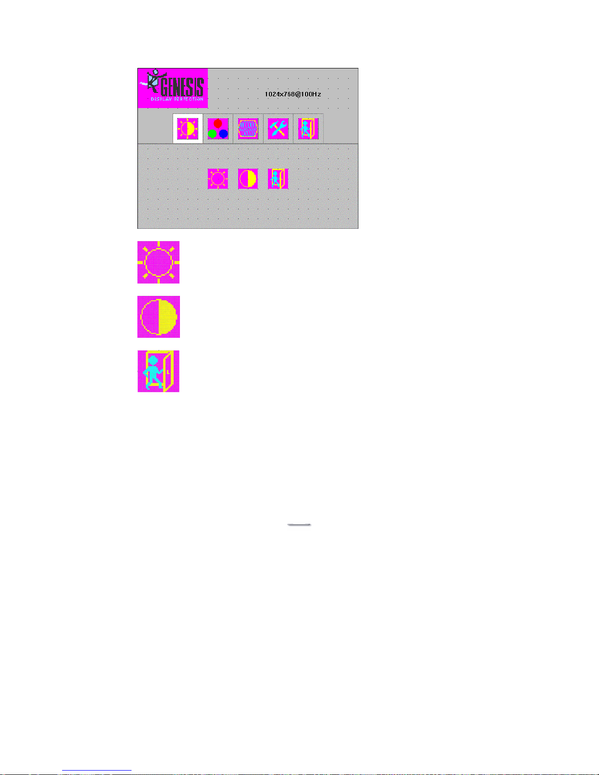
OSD Menu Structure
This item will adjust the brightness of the screen. This
function will adjust the offset value of ADC. Setting this value
too high or too low will destroy the quality of image.
This item will adjust the contrast of the screen. This function
will adjust the gain value of ADC. Adjust this value too high or
too low will destroy the quality of image.
Values are from 0 to 255
Press the EXIT key to upper level.
Functions include:
[Brightness]
[Contrast]
[Exit]
Page 12
USB Aegis – Series
`11
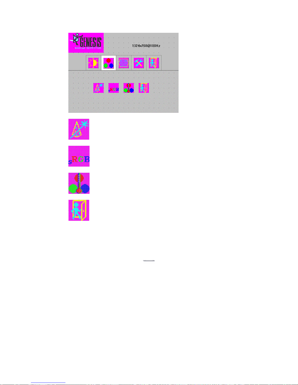
This item will automatically adjust color.
Press the EXIT key to upper level.
This item includes user colors 4200K, 5000K,
6500K, 7500K, 9300K.
RGB User color values are from 0 to 255.
Functions include:
[Auto color]
[S RGB]
[Color temp]
[Exit]
Standard RGB mode
Page 13
USB Aegis – Series
`12
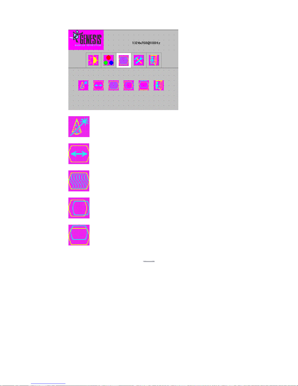
This item will adjust horizontal display position of the
image. Values are from 0 to 100
This item will adjust vertical display position
of image. Value from 0 to 100
This item will adjust the sampling Phase.
Value from 0 to 32.
This item will automatically adjust the H/V position,
frequency, phase, and black level.
Extend screen in display.
Value from 0 to 100
Functions include:
[Auto adjust]
[Extend screen]
[Phase adjust]
[H position adjust]
[V position adjust]
[Exit]
Page 14
USB Aegis – Series
`13
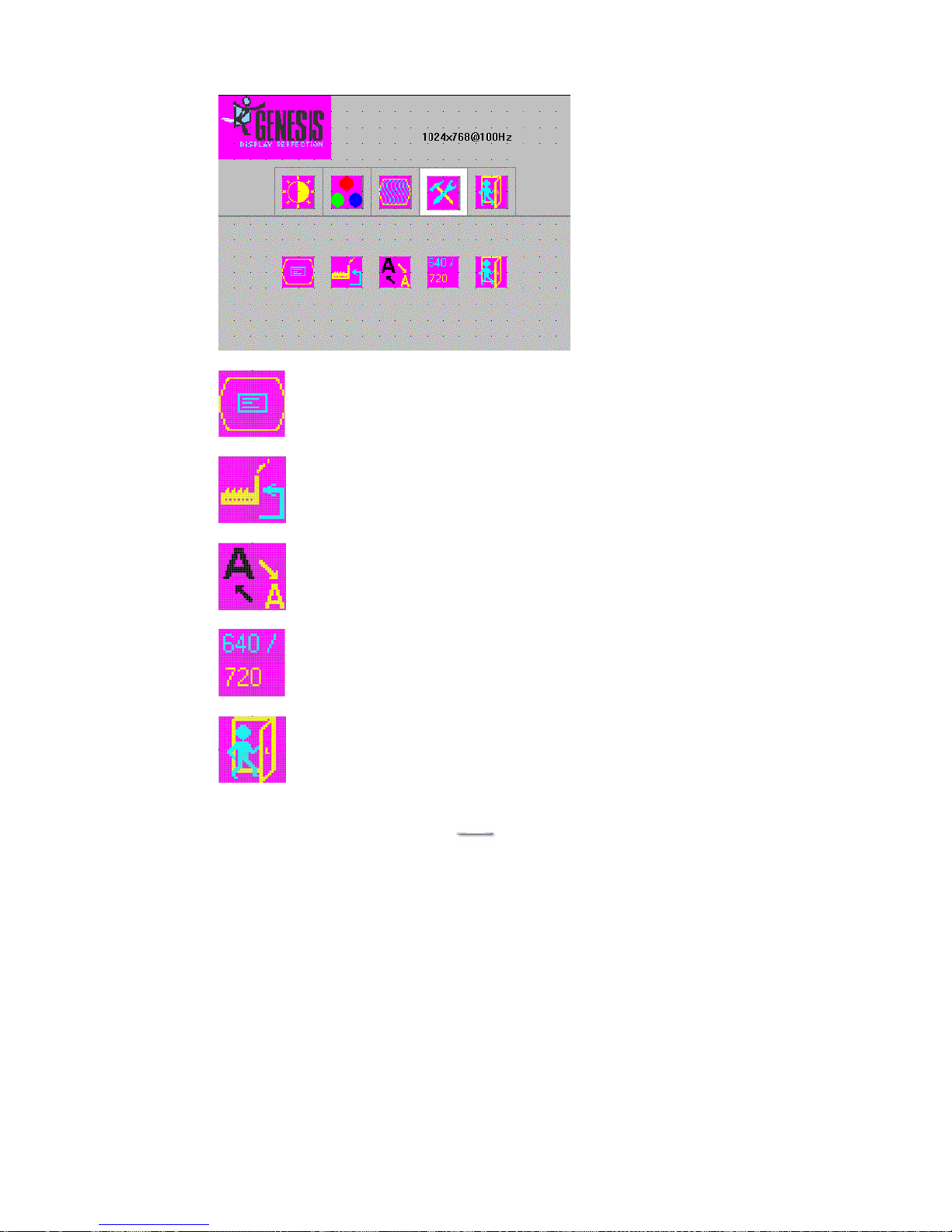
OSD detail function, include OSD maintain time
(Value from 0 to 60), OSD icon H/V position adjust
(Value from 0 to 100).
Factory reset, press this item to load default value.
Press the EXIT key to upper level.
Functions include:
[OSD detail]
[Factory reset]
[Sharpness]
[640 / 720]
[Exit]
640 / 720 mode change.
Sharpness function.
Value from 0 to 6
Page 15
USB Aegis – Series
`14
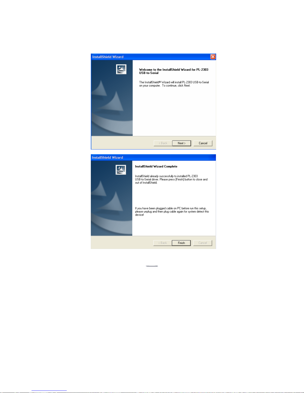
USB-to Serial Driver Installation
1. Insert the FEC Utility CD and Locate D:\Usb-Aegis\PL-2303HX
2. Select the relevant operating system folder that you are using.
3. Shown below are self-explanatory examples for Windows 2k & XP.
Page 16
USB Aegis – Series
`15
ELO Touch Tools Installation
ELO Touch Tools Installation for all Windows Operating Systems
1. Insert the FEC Utility CD and Locate D:\TOUCHSCREEN
2. Select the relevant ELO folder for the operating system that you are using.
Example. If you are installing for a Windows 98 system, then select EloWin98.
If you are installing under Windows 2000 or XP and you have only one Aegis
touchscreen monitor then select Elo Single Touch 2K_XP,if you have a Host
PC with 2 or more Aegis touchscreen monitors then select Elo Multi Touch
2K_XP.
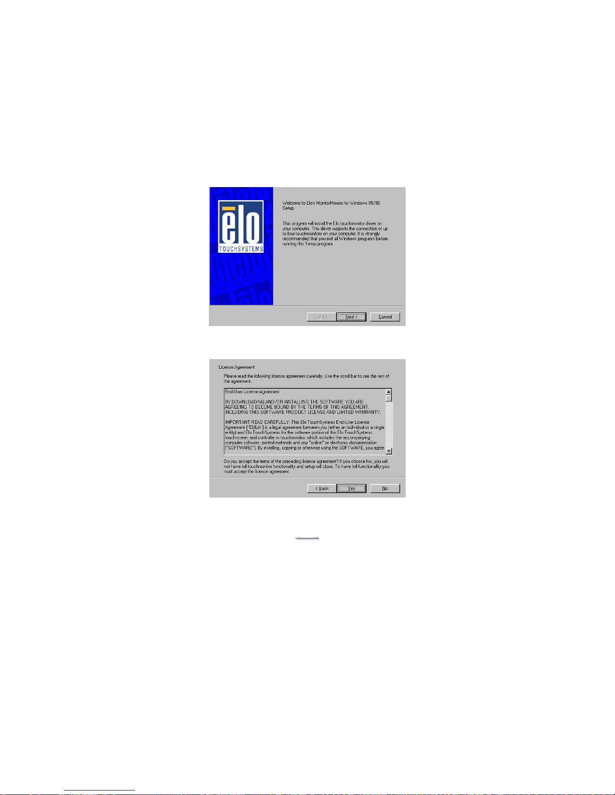
3. Run Setup.exe
1. Click Next.
2. Read the “License Agreement” and click Yes if you accept it.
Page 17
USB Aegis – Series
`16
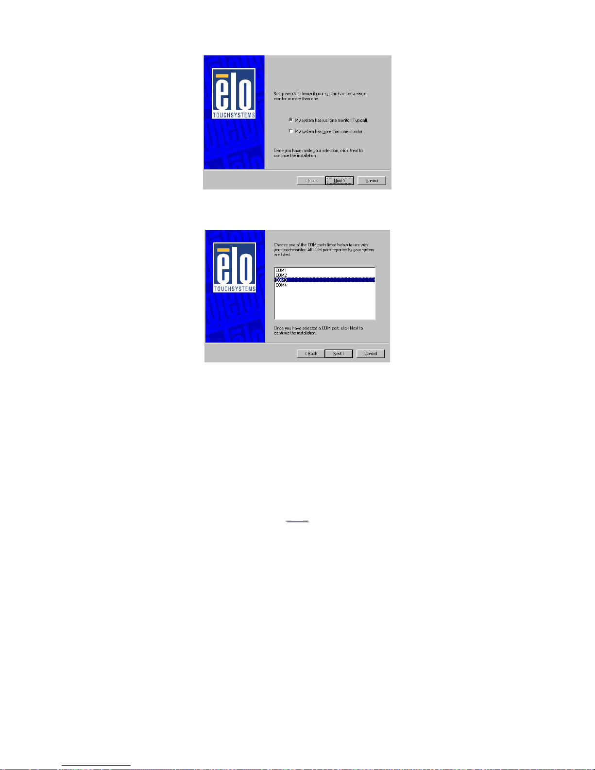
3. Select if you have one or two monitors and click Next.
4. Select the COM port for the monitor. It is recommended that you select
COM3 for primary touch screen and COM4 for second touch screen. Press
Next.
Page 18
USB Aegis – Series
`17
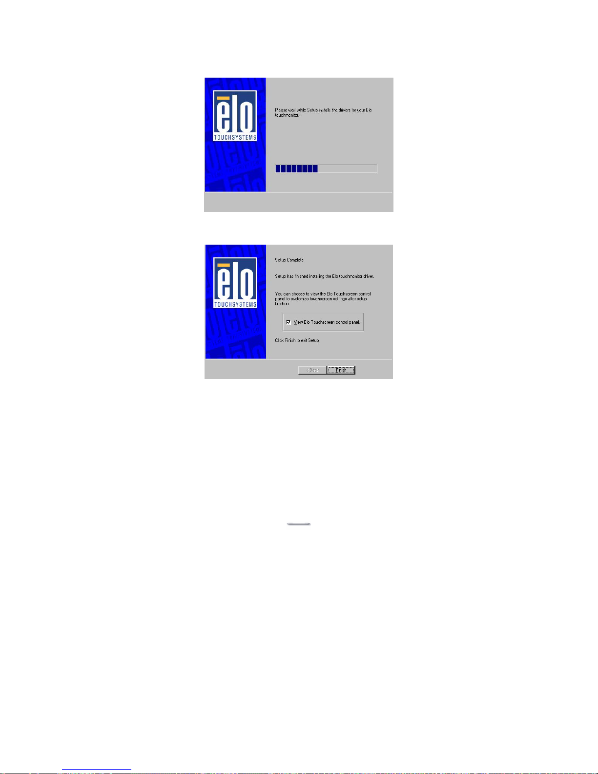
5. Wait until the ELO Touch Tools have been installed.
6. Select View ELO touch screen control panel and click Finish.
The Host PC will reboot automatically.
After the Host has rebooted, follow the directions to calibrate the touch screen.
Page 19
USB Aegis – Series
`18
ELO Control Panel
This section explains the different options in the ELO control Panel.
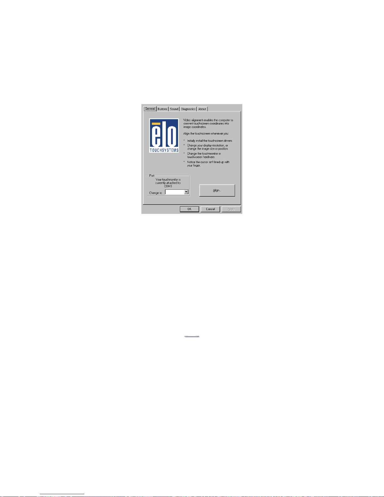
General tab
The general tab allows you to:
¾ Change the COM port your touch screen is set to.
¾ Calibrate the touch screen with the Align button.
Page 20
USB Aegis – Series
`19
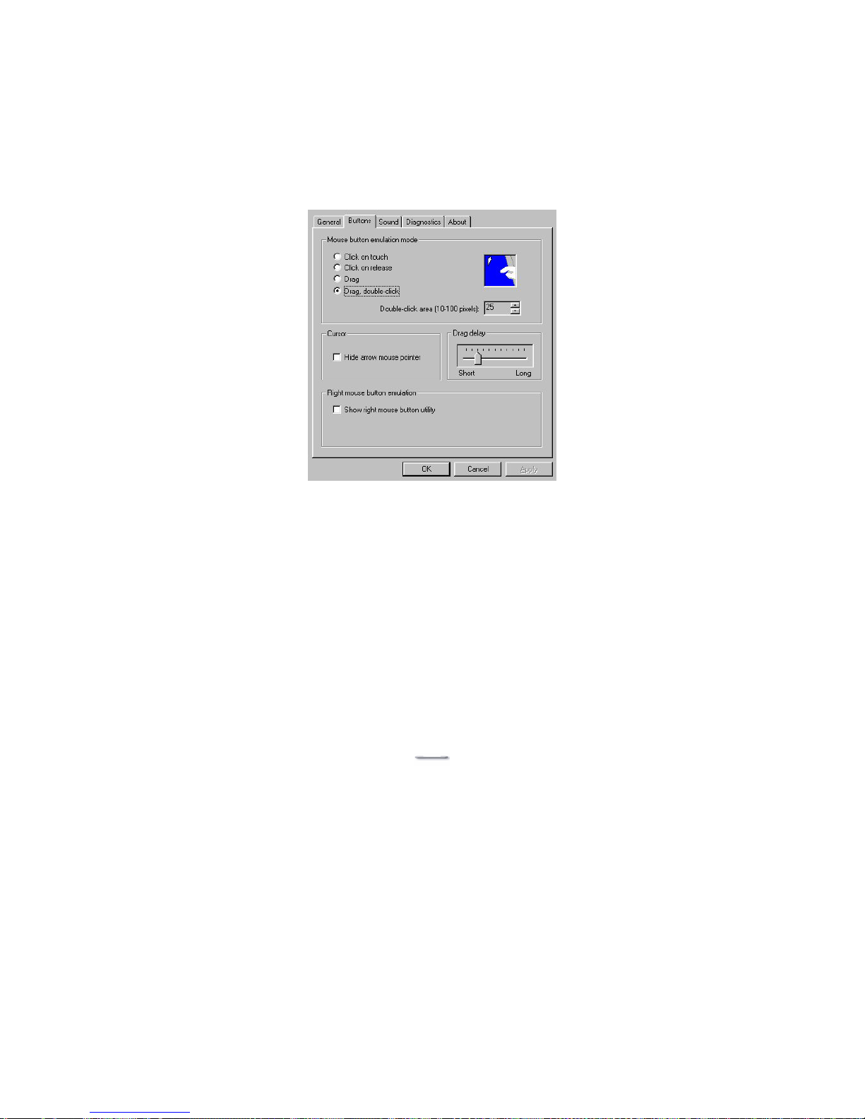
Buttons tab
The Buttons tab allows you to:
¾ Adjust all mouse emulation controls.
¾ Change cursor properties.
¾ Enable or disable right mouse button utility.
Page 21
USB Aegis – Series
`20
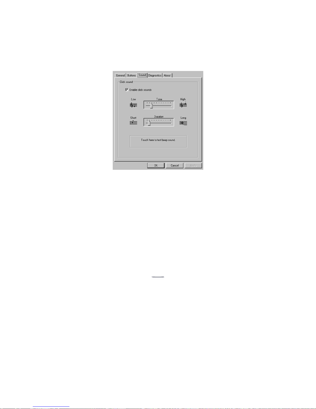
Sound tab
The Sound tab allows you to:
¾ To change sound properties for ELO touch tools.
Page 22
USB Aegis – Series
`21
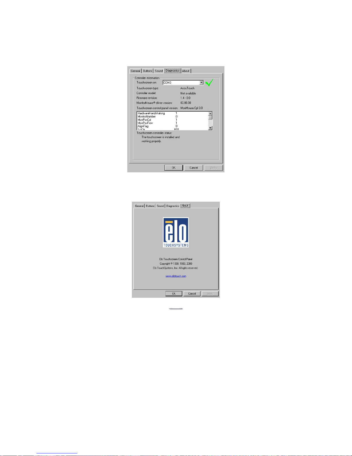
Diagnostics tab
The Diagnostics tab allows you to:
¾ View Controller Information.
About tab
The About tab displays Information about ELO Touchsystems
Page 23
USB Aegis – Series
`22
I/O Board Configuration
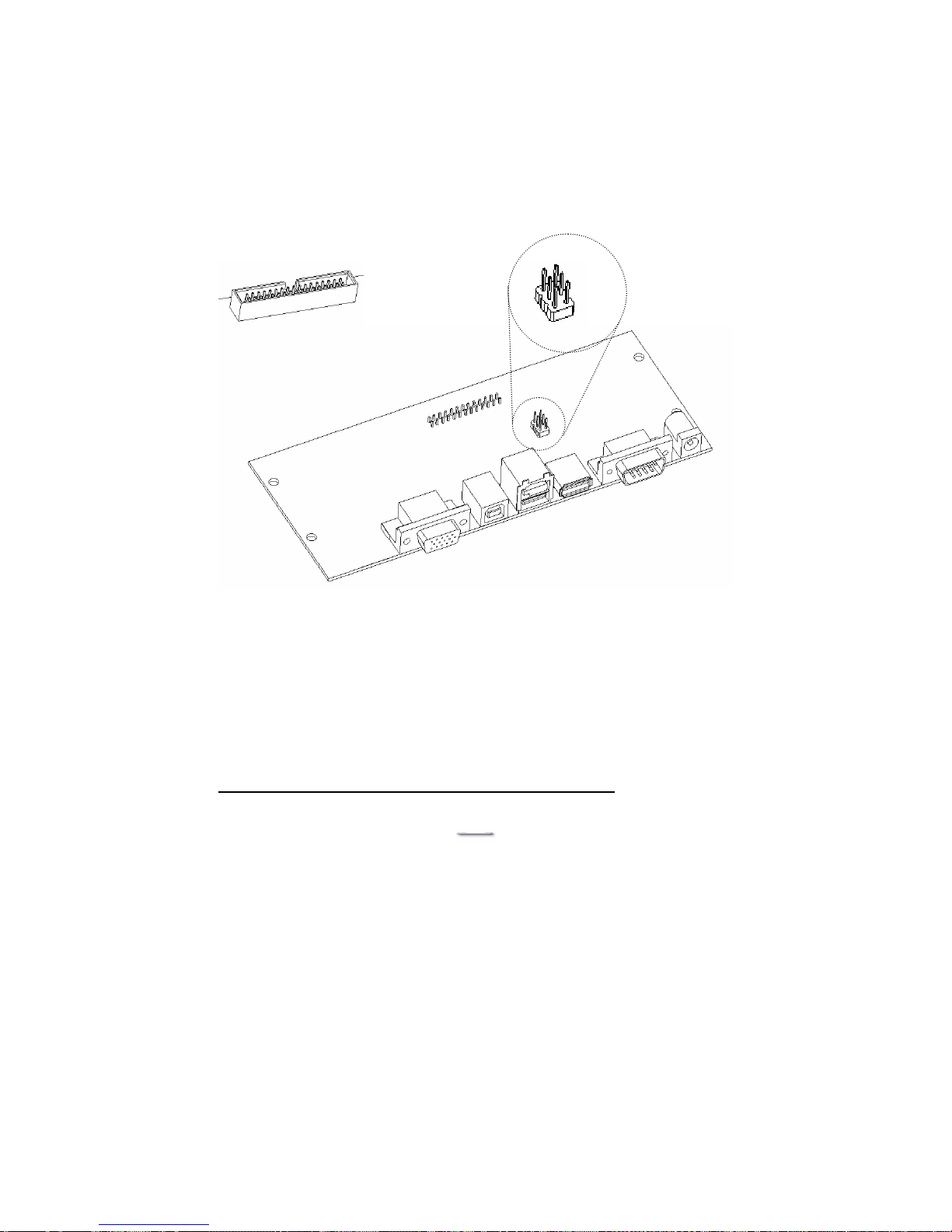
There is only 1 physical main I/O board (9000PB0650) This I/O board connects
all secondary I/O boards, devices and ports. The following diagrams and
tables explain in detail the connector assignments and uses.
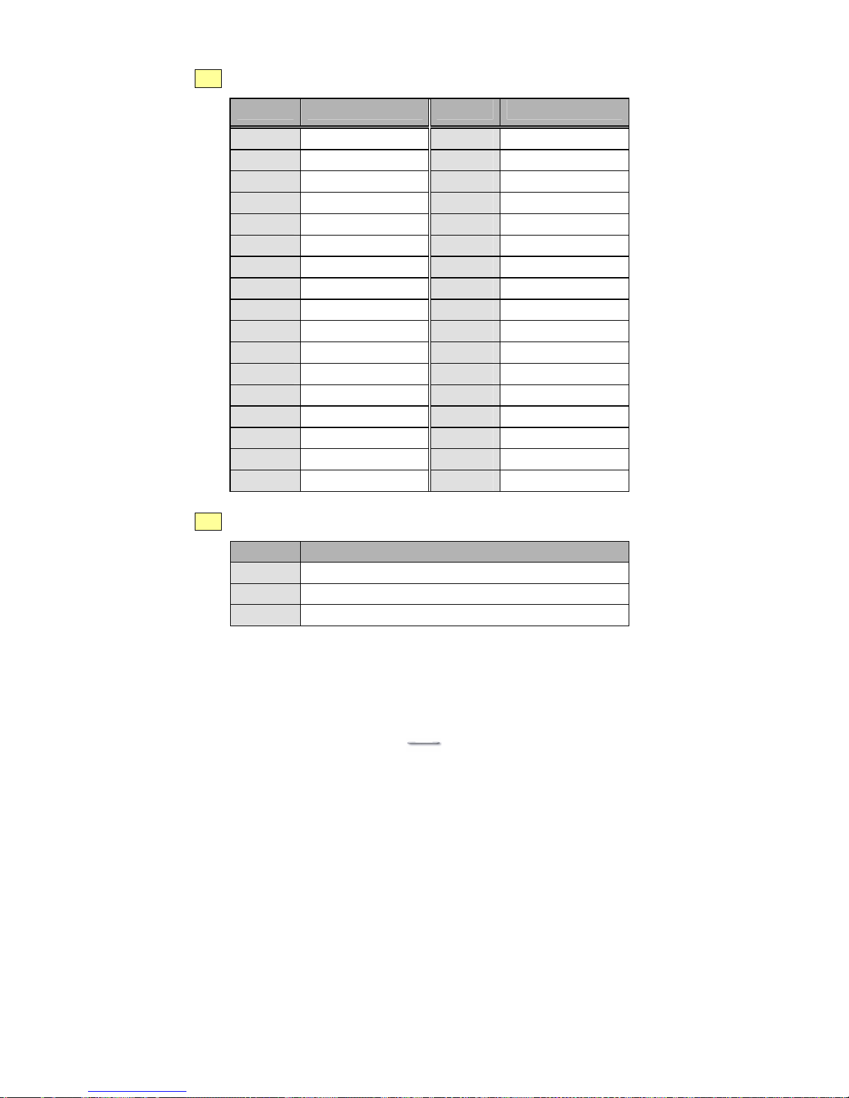
Connector JP1 (which is on the reverse “bottom” side of the I/O board) is a
multi device connector. All internal devices are attached to this socket via a 34way ribbon cable which is physically keyed so that can only be inserted one
way into the JP1 socket.
The RS232 port Pin 9 can be made to supply power to RS232 peripherals that
require either +12 volts or +5 volts, or it can be set to be the standard Ring
Input (RI) signal generally associated with modem use.
JP2 is the function selector for the RS232 port.
Only one jumper is ever used on this selector at any time
.
+12
+5
RI
JP2
JP1
bottom side
I/O Bus connector
9000PB0650 I/O Board
VGA1
CON4
CON3
CON2
CON1
J1
CON5
Page 24
USB Aegis – Series
`23
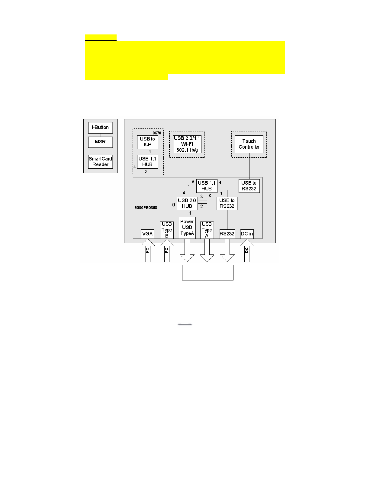
Shown below is a diagram of the USB connections and port numbering.
Please note:
At document creation time, the MSR used in the diagram below is a specific
type and is not interchangeable with other MSR modules used with other FEC
POS models. The reason being, if you need to reprogram the MSR for country
specific or special formatting, then it has to be programmed via a USB
connection. The required Windows utility to perform this MSR reprogramming
task is included on the driver CD.
Additional External
Peripheral devices
Page 25
USB Aegis – Series
`24
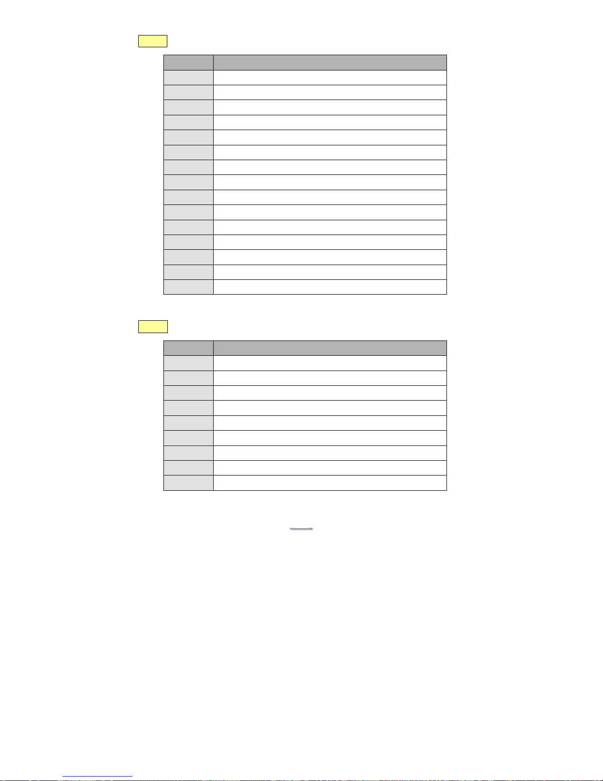
VGA1 VGA port
PIN No. Description
1
RED
2
GREEN
3
BLUE
4
NC
5
GND
6
GND
7
GND
8
GND
9
NC
10
GND
11
NC
12
SM DATA
13
SM CLK
14
V-SYNC
15
H-SYNC
CON1 USB to RS232 port
PIN No. Description
1
DCD
2
RXD
3
TXD
4
DTR
5
GND
6
DSR
7
RTS
8
CTS
9
RI/DC output (RI is the default setting)
Page 26
USB Aegis – Series
`25
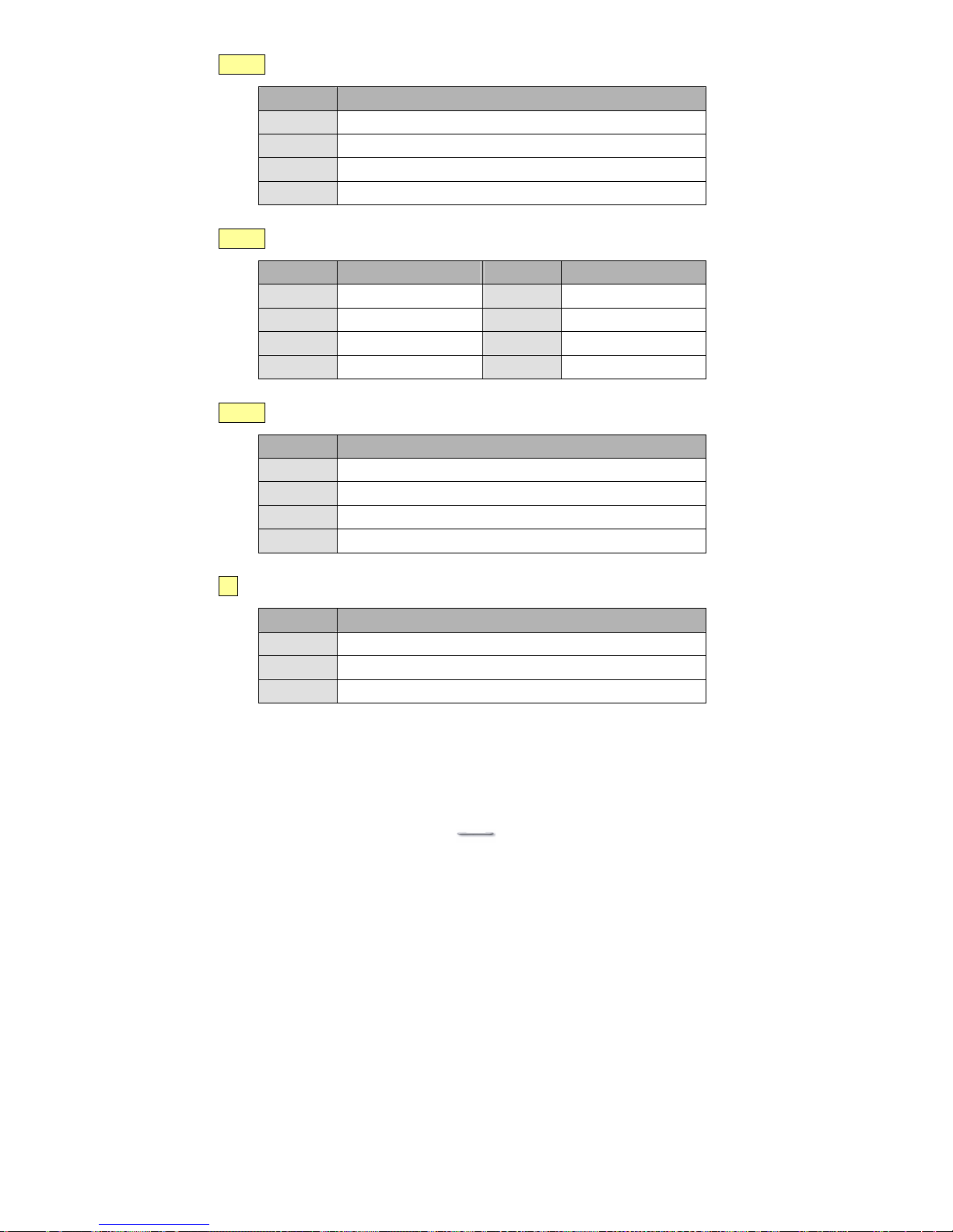
CON2 USB 2.0 downstream port
PIN No. Description
1
+5V
2
USB2.0_2-
3
USB2.0_2+
4
GND
CON3 POWERED USB 2.0 downstream port
PIN No. Description PIN No. Description
1
+5V
5
GND
2
USB2.0_1-
6
+12V
3
USB2.0_1+
7
+12V
4
GND
8
GND
CON4 USB 2.0 upstream port
PIN No. Description
1
+5V
2
USB2.0_0-
3
USB2.0_0+
4
GND
J1 DC port (DC +12V inport)
PIN No. Description
1
+12V
2
GND
3
NC
Page 27
USB Aegis – Series
`26
JP1 I/O Bus connector
PIN No Description PIN No Description
1
KB-CLK
2
AGND
3
KB-DATA
4
PC-CLK
5
+5V
6
PC-DATA
7
H-SYNC
8
V-SYNC
9
SM DATA
10
BLUE
11
SM CLK
12
GREEN
13
AGND
14
RED
15
USB_2+
16
USB_2-
17
AGND
18
VCC
19
USB_3+
20
USB_3-
21
AGND
22
VCC
23
USB2.0_4+
24
USB2.0_4-
25
AGND
26
VCC
27
DTR
28
CTS
29
TXD
30
RTS
31
RXD
32
DSR
33
+12V
34
AGND
JP2 RS232 Power selector Jumpers
PIN No. Description
1-2
+12V
3-4
RI
5-6
+5V
Page 28

USB Aegis – Series
`27
Hardware Installation
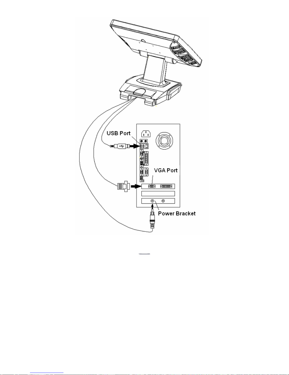
Model U152TA / U12xTA
1. Turn off the computer.
2. Put the USB Aegis on a steady surface.
3. (Please refer to the External Power Adapter section for instruction on using
an external power adapter and skip this step).
Powering from the host computer through the Power Bracket:
a. Open the computer case.
b. Secure the Power Bracket to an unused expansion slot bracket location.
c. Connect the connector on the Power Bracket wire assembly to a
matching one from computer power supply.
d. Close the computer case.
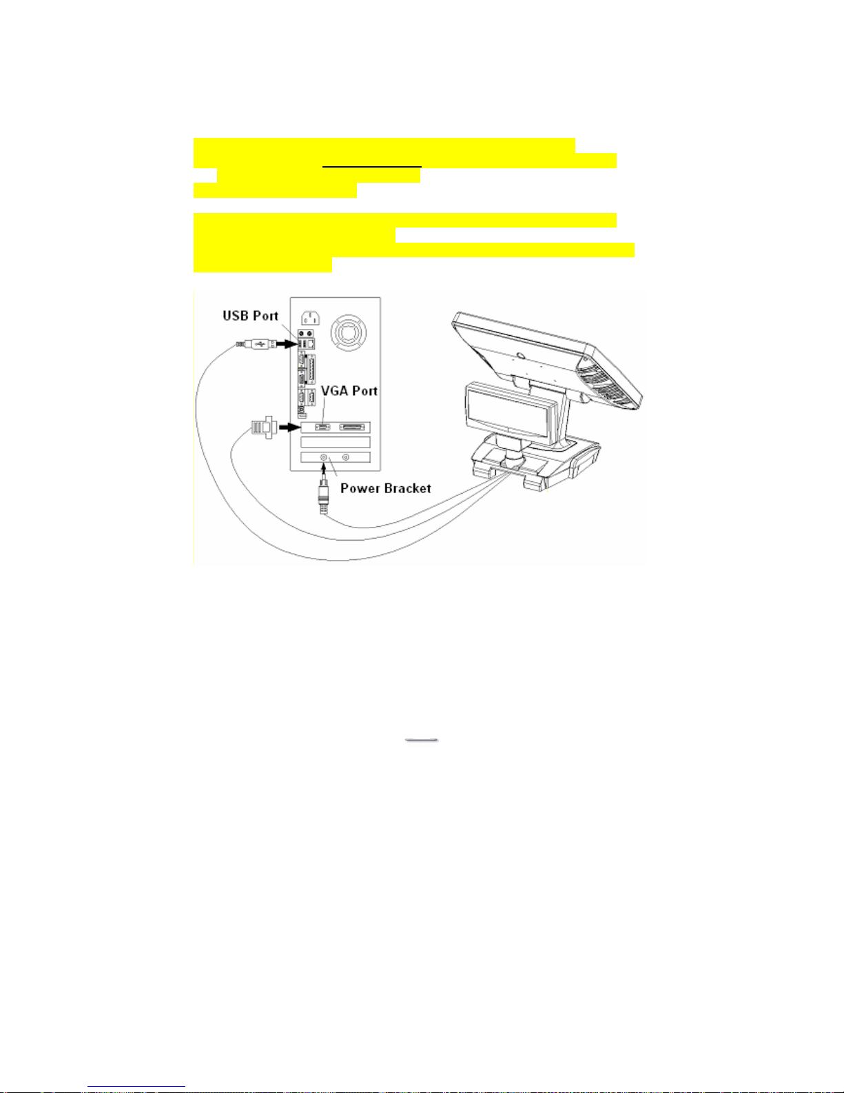
e. Connect the USB Aegis Power Cable to the connector on the
Power Bracket.
4. Connect the VGA Cable to the VGA port on the computer.
5. Connect the USB Cable to the USB port on the computer.
Page 29
USB Aegis – Series
`28
錯誤!
Page 30
USB Aegis – Series
`29
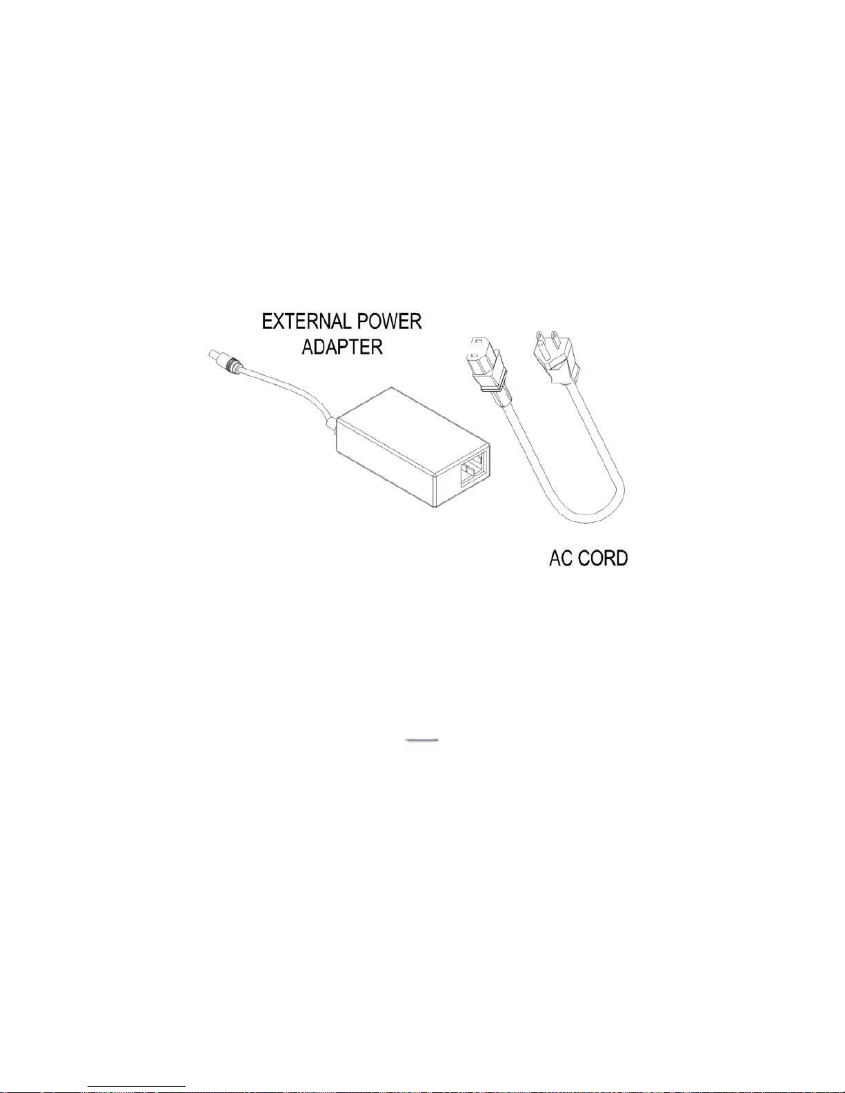
External Power Adapter (optional)
For situations where the Power Bracket cannot be used to power the USB
Aegis, an optional External Power Adapter can be used instead.
1. Check the items in the External Power Adapter kit, including a power
adapter and an AC cord.
2. Turn off power to the computer and turn the USB Aegis power switch to off.
3. Insert the Power Adapter jack plug to the USB Aegis Power jack socket.
4. Connect the AC plug of the Power Adapter to a 110/240-volt AC outlet.
Page 31
USB Aegis – Series
`30
MCR Installation
Please note: throughout this document references are made to MCR and MSR,
they are in fact the same thing.
(MCR = Magnetic Card Reader)
(MSR = Magnetic Stripe Reader)
The MCR option can be fitted to the right side of USB Aegis. This option allows
the reading of magnetic stripe card through keyboard input.
* If there is a need to modify the MCR parameters, such as country code and
track combination, please follow the instruction in the section,
MCR Parameter Modification.
Page 32
USB Aegis – Series
`31
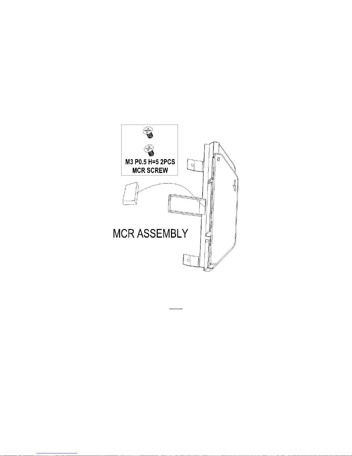
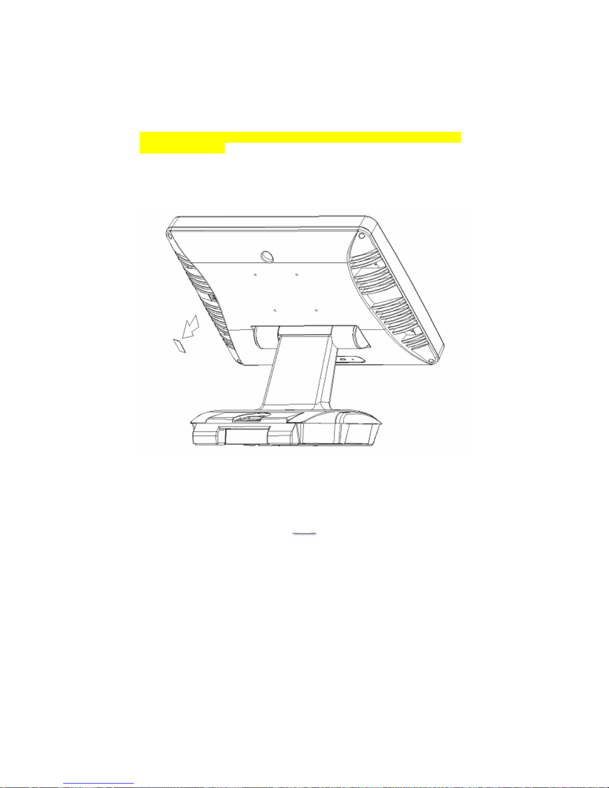
1. Check the items in the MCR option kit.
2. Turn off Power to the USB Aegis and the computer.
3. Remove the MSR cover plate that can be found on the right side and to the
rear of the main Unit
Page 33

USB Aegis – Series
`32
Page 34
USB Aegis – Series
`33
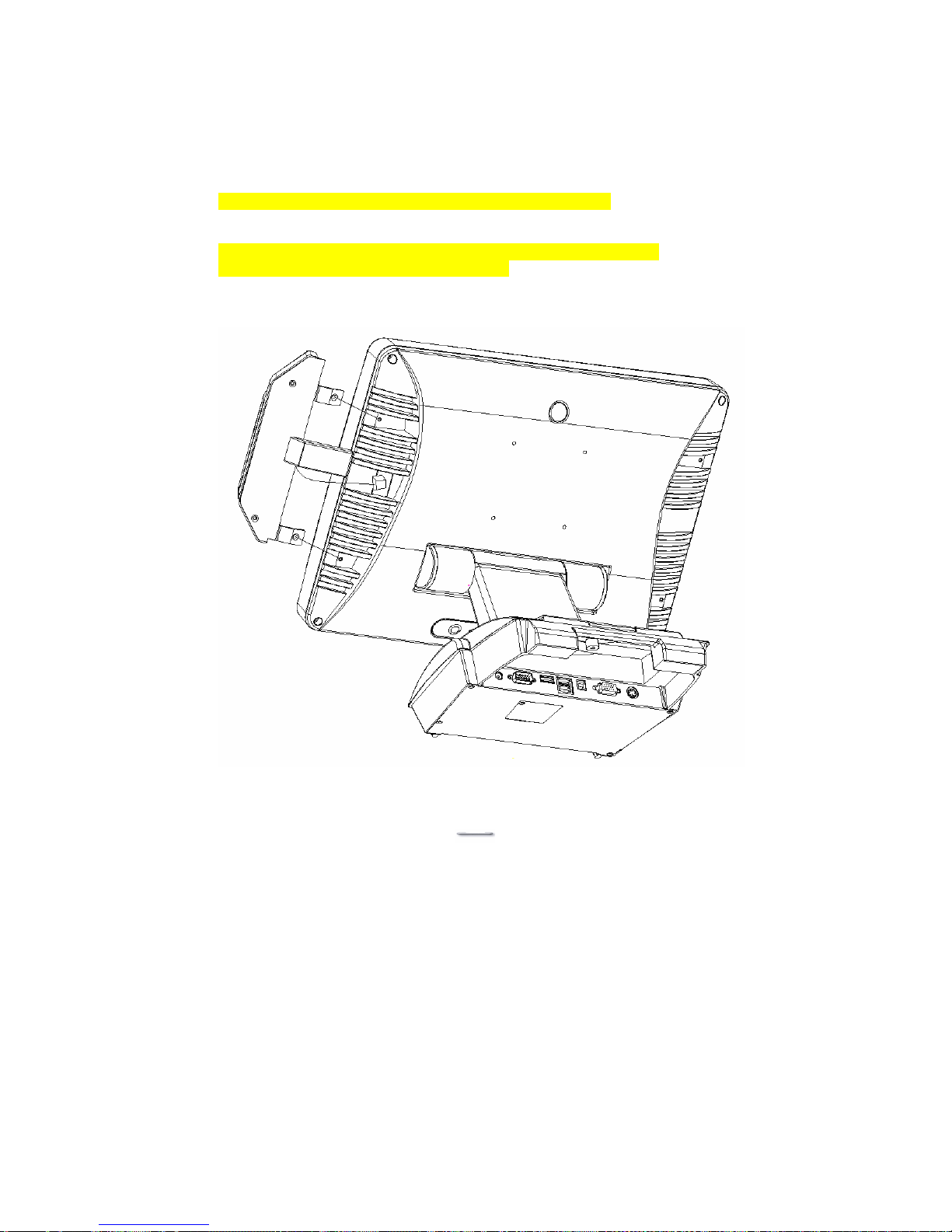
4. Attach the MCR Assembly to the main unit and connect the MCR
cable to the MCR socket.
5. Secure the MCR to the main unit with 2 screws.
6. Turn on USB Aegis power.
7. Put the back cover on USB Aegis and secure with screws.
* If the MCR is taken off, the loopback plug must be re-inserted.
Otherwise, the keyboard will not function.
Page 35

USB Aegis – Series
`34
MCR Parameter Modification
This option is for users who need to customize the MCR parameters for a
particular task.
Some of the useful parameters include:
The selection of country code, other than the default English.
The choice of track combinations.
The preamble/postamble codes.
The MCR parameters can be modified by using the supplied utility program.
The utility can be found on the CD that came with your system in the “Utilities”
folder. The program name is msr_v12_win.zip.
If you are upgrading and earlier system to include our MCR reader, then this
utility can be located on our website at: -
http://www.firich.com.tw/tech_drivers.htm in the section labelled “MSR Utility”.
Unzip this file onto your system hard disk, in a folder of your choice.
It will also create 3 subfolders named Disk1, Disk2, and Disk3.
Change to the folder “Disk1” and run the “Setup.exe” program, and follow the
simple onscreen instructions.
When the installation finishes, you will find that a new folder has been created
in your “Program files” folder, labelled as “Decoder” with a subfolder named
“S64 Decoder”
Now change folder to C:\Program Files\Decoder\S64 Decoder and run the
program named “S64_cfg.exe”
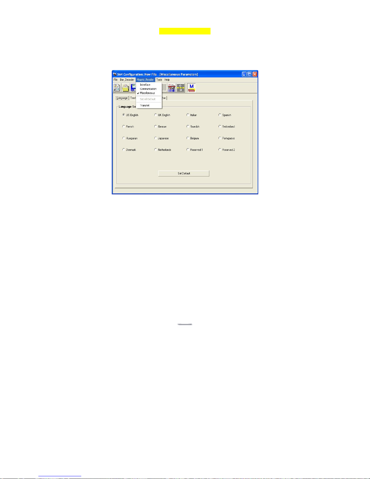
When the program has loaded please select the Magnic_Reader menu item
as in the following picture.
By using the 3 top items listed; Interface, Communication, and
Miscellaneous, you will be able to alter many of the parameters associated
with the MCR unit.
When you have finished your modifications and are sure that they are set
exactly how you want them to be, just click on the menu item Transmit to
download the new parameter to the MCR unit.
Please refer to the Help menu for any further assistance.
Page 36
USB Aegis – Series
`35
MCR Utility Reader
Page 37
USB Aegis – Series
`36
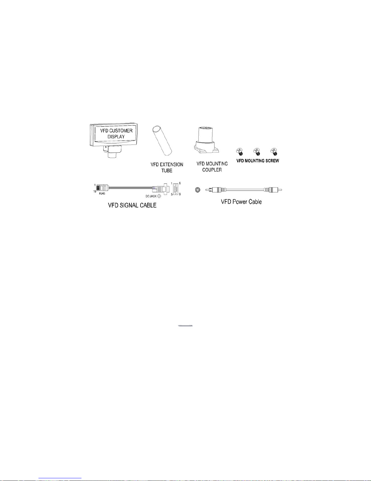
VFD Customer Display Installation
1. Check the items in the VFD Customer Display Kit.
Page 38
USB Aegis – Series
`37
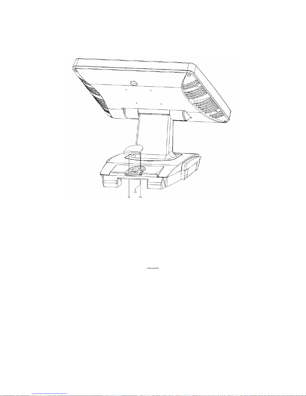
2. Turn off power to USB Aegis and to the computer.
3. Remove the VFD Mounting Cover from the Base of USB Aegis.
Page 39
USB Aegis – Series
`38
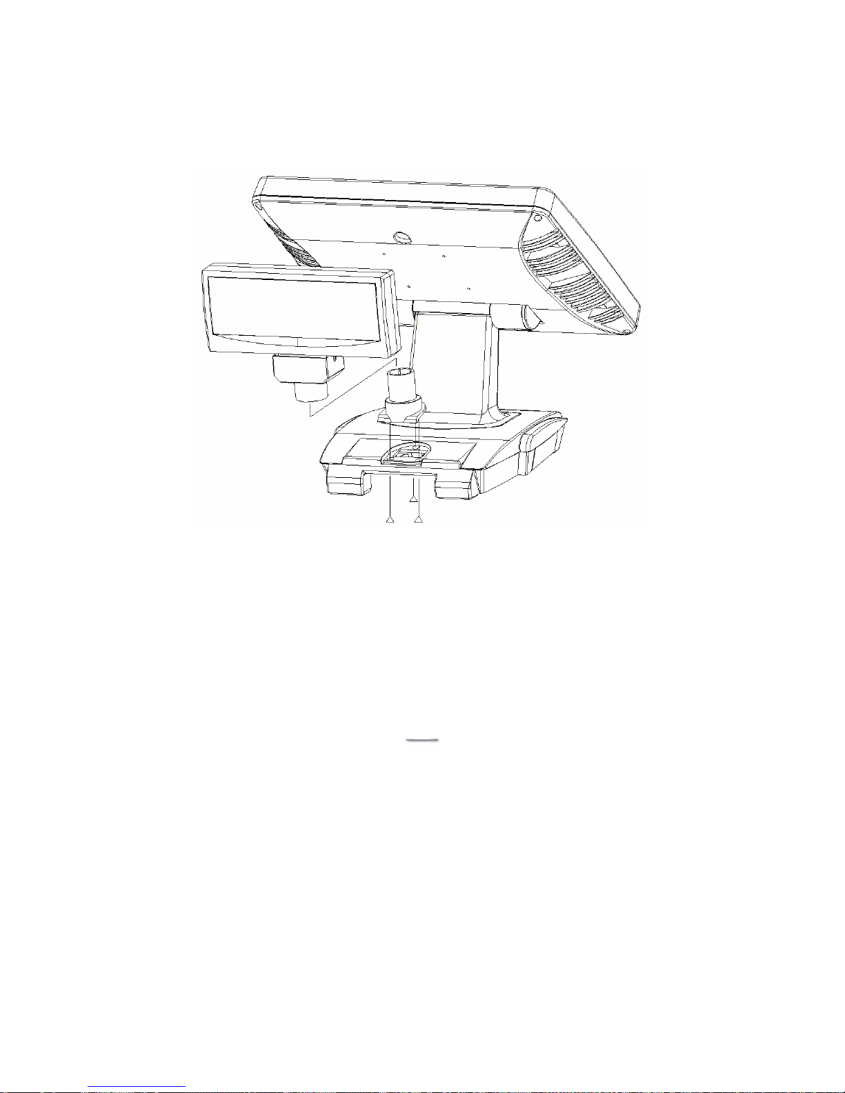
4. Secure the VFD Mounting Coupler to the Base with three VFD Mounting
Screws.
Page 40
USB Aegis – Series
`39
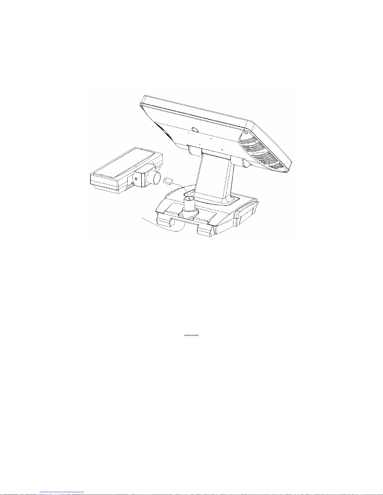
5. Thread the RJ-45 phone connector of the VFD Signal Cable through the
VFD Mounting Coupler, from the bottom of USB Aegis.
6. Plug the RJ-45 connector into the VFD Customer Display.
Page 41
USB Aegis – Series
`40
7. Fit the VFD Customer Display onto the VFD Mounting Coupler.
8. Plug the DB9M connector of the VFD Signal Cable to the external RS232
COM port on the main I/O board 9000PB0650.
9. Remove the base cover to expose the 9000PB0650 I/O board.
10. On JP2 Place the one and one only Jumper between pins 1-2 this will
supply +12volts to the VFD display.
11. Replace the base cover.
The VFD display now only needs to be configured for country specific and
communication parameter settings.
Please refer to the manual that came with the VFD on how to set it up via the
accessible dip switches.
Page 42

USB Aegis – Series
`41
Trouble Shooting
When encountering difficulties in using this product, please follow the steps
below. If the problem persists, please contact the dealer.
1. No picture on screen
a. Check the AC cord and signal cable. Make sure they are properly
connected.
b. Check that the power button on the OSD panel is turned on.
c. Check if the computer has entered energy saving mode.
2. Abnormal display colour
a. Check if the signal cable is properly connected to the computer.
b. For model U152TA / U12xTA, using the on-screen-adjustment
mode to adjust the colour parameters.
3. Skewed or distorted display
a. Check if the signal cable is properly connected to the computer.
b. For model U152TA /U12xTA, using the on-screen-adjustment
mode to adjust the geometric parameters.
4. Picture too large or too small
a. Check if the display resolution is set correctly in the operating system.
b. For model U152TA / U12xTA, using the on-screen-adjustment mode to
adjust the size parameters.
5. Touch screen does not work
a. Check if the COM port cable is properly connected to the computer.
b. Check if the Elo touch driver has been loaded properly.
c. Check if the COM port number is set correctly.
6. VFD Customer Display does not display properly
a. Check if the power & signal cables are connected properly.
b. Check whether the power switch is turned on.
7. Magnetic Card Reader does not work
a. Check if the MCR Connector is properly connected to the MCR socket
on the rear of the unit.
8. The card swipe character(s) is incorrect or shows random characters
a. The country code parameter setting may need modification, please
refer to the section, MCR Parameter Modifications.
 Loading...