

Page 1
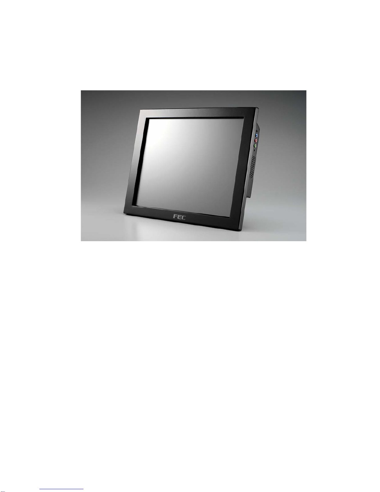
UUsseerr''ss MMaannuuaall
PP-9260 series
Page 2

Federal Communications Commission (FCC)
This equipment has been tested and found to comply with the limits for a Class A digital device,
pursuant to Part 15 of the FCC Rules. These limits are designed to provide reasonable
protection against harmful interference in a residential installation. This equipment generates,
uses, and can radiate radio frequency energy and, if not installed and used in accordance with
the instructions, may cause harmful interference to radio communications. However, there is no
guarantee that interference will not occur in a particular installation. If this equipment does
cause harmful interference to radio or television reception, which can be determined by turning
the equipment off and on, the user is encouraged to try to correct the interference by one or
more of the following measures:
Reorient or relocate the receiving antenna.
Increase the separation between the equipment and the receiver.
Connect the equipment to an outlet on a circuit different from that to which the receiver is
connected.
Consult the dealer or an experienced radio/TV technician for help.
Shielded interconnect cables and shielded AC power cables must be employed with this
equipment to insure compliance with the pertinent RF emission limits governing this device.
Changes or modifications not expressly approved by the system’s manufacturer could void the
user’s authority to operate the equipment.
Declaration of Conformity
This device complies with part 15 of the FCC Rules. Operation is subject to the following two
conditions:
1. This device may not cause harmful interference, and
2. This device must accept any interference received, including interference that may cause
undesired operation.
Page 3

Important Safety Information
SAFETY INSTRUCTIONS
1. Please read these safety instructions carefully.
2. Keep this User’s Manual for later reference.
3. Don’t use liquid or spray detergent for cleaning. Use only a moistened sheet or cloth.
4. For pluggable equipment, the socket-outlet should be installed near the equipment and
should be easily accessible.
5. Keep this equipment from extreme humidity areas.
6. Lay this equipment on a stable surface when installing.
7. Do not leave this equipment in a non-air conditioned environment, or in a storage
temperature above 40 C. Such conditions may damage the equipment.∘
10. Place the power cord so that it will not be stepped on. Do not place anything over the
power cord. The power cord must be rated for the product and for the voltage and current
marked on the product’s electrical ratings label. The voltage and current rating of the cord
should be greater than the voltage and current rating marked on the product.
11. All cautions and warnings on the equipment should be noted.
12. If the equipment is not used for a long time, disconnect the equipment from the mains to
avoid damage.
14. Never open the equipment. For safety reasons, qualified service personnel should only
open the equipment.
15. If one of the following situations arises, get the equipment checked by service personnel:
a. The Power cord or plug is damaged.
b. Liquid has penetrated the equipment.
c. The equipment has been exposed to extreme moisture conditions.
d. The equipment does not work well or you cannot get it work according to the user’s
manual.
e. The Equipment has been dropped and damaged.
f. The equipment has obvious signs of damage.Copyright
The information in this guide is subject to change without prior notice.
The manufacturer shall not be liable for technical or editorial errors or omissions contained
herein, nor for incidental or consequential damages resulting from the furnishing, performance,
or use of this material.
This manual contains information protected by copyright. No part of this manual may be
photocopied or reproduced in any form without prior written consent from the manufacturer.
© 2008 All rights reserved.
The software described in this guide is furnished under a license agreement or nondisclosure
agreement. The software may be used or copied only in accordance with the terms of the
agreement.
Product names mentioned herein may be trademarks and/or registered trademarks of their
respective companies.
First Edition July 2008
Page 4

TTaabbllee ooff CCoonntteenntt
II NN DD EE XX
PPaaggeess
CChhaapptteerr 11 IInnttrroodduuccttiioonn
11
……HHooww ttoo uussee tthhiiss mmaannuuaall
11
……WWhhaatt ccoommeess wwiitthh PPPP--99226655//99226677
22
……DDiimmeennssiioonnss
33
……PPPP--99226600 AAsssseemmbbllee
55
……HHaarrdd DDiisskk DDrriivvee IInnssttaallllaattiioonn
77
CChhaapptteerr 22 SSooffttwwaarree SSeettuupp
99
……WWiinnddoowwss XXPP IInnssttaallllaattiioonn
99
……DDeevviiccee DDrriivveerr IInnssttaallllaattiinn
1100
……IInntteell CChhiippsseett DDrriivveerr IInnssttaallllaattiioonn ffoorr WWiinnddoowwss
XXPP O
Oppeerraattiinngg SSyysstteemm
1100
……GGrraapphhiiccss DDrriivveerr IInnssttaallllaattiioonn
1144
……EEnnaabbllee sseeccoonndd ddiissppllaayy
1188
……EEtthheerrnneett DDrriivveerr IInnssttaallllaattiioonn
2233
……AAuuddiioo DDrriivveerr IInnssttaallllaattiioonn
2255
……TToouucchhSSccrreeeenn DDrriivveerr IInnssttaallllaattiioonn ((EElloo
RReessiissttiivvee//IIRR
ttoouucchh))
2277
……EElloo CCoonnttrrooll PPaanneell
3322
……TToouucchhKKiitt TToooollss IInnssttaallllaattiioonn
3377
……TToouucchhKKiitt CCoonnttrrooll PPaanneell
4433
CChhaapptteerr 33 SSppeecciiffiiccaattiioonnss
4488
……SSyysstteemm ssppeecciiffiiccaattiioonnss
4488
……MMootthheerrbbooaarrdd ccoonniigguurraattiioonnss
5500
……SSAATTAA ddoocckkiinngg bbooaarrdd
5555
……PPPP--99226655 II//OO bbooaarrdd
5566
……PPPP--99226677 II//OO bbooaarrdd
5599
……PPPP--99226655 ssyysstteemm II//OO ppaanneell
6611
……PPPP--99226677 ssyysstteemm II//OO ppaanneell
6611
Page 5

PP-9260 series user’s manual ver 1.0
1
CChhaapptteerr 11
IInnttrroodduuccttiioonn
How to Use This Manual
This manual contains all the information you need to set up and use PP-9265/PP-9267. In
addition, you can also consult the manuals for the operating system and any additional hardware
manuals for peripherals that you may have added.
Chapter 1 An introduction to PP-9265/PP-9267 and this manual.
Chapter 2 All necessary information for all hardware setup.
Chapter 3 The necessary information for installing the video drivers, touch screen tools,
audio and LAN drivers.
Chapter 4 Lists all PP-9265/PP-9267 specifications and Information for the motherboard
configuration
Page 6

PP-9260 series user’s manual ver 1.0
2
What comes with PP-9265/PP-9267
The following items are standard peripherals with PP-9265/PP-9267:
• User’s Driver / Utility disk
• AC power cord
• Power adaptor
• Wall mount brackets
• Screws
Page 7
PP-9260 series user’s manual ver 1.0
3
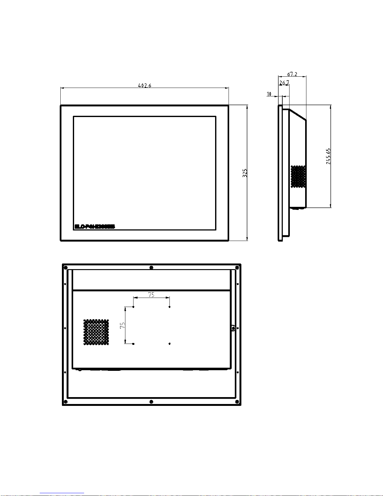
Dimensions
PP-9267
Page 8
PP-9260 series user’s manual ver 1.0
4
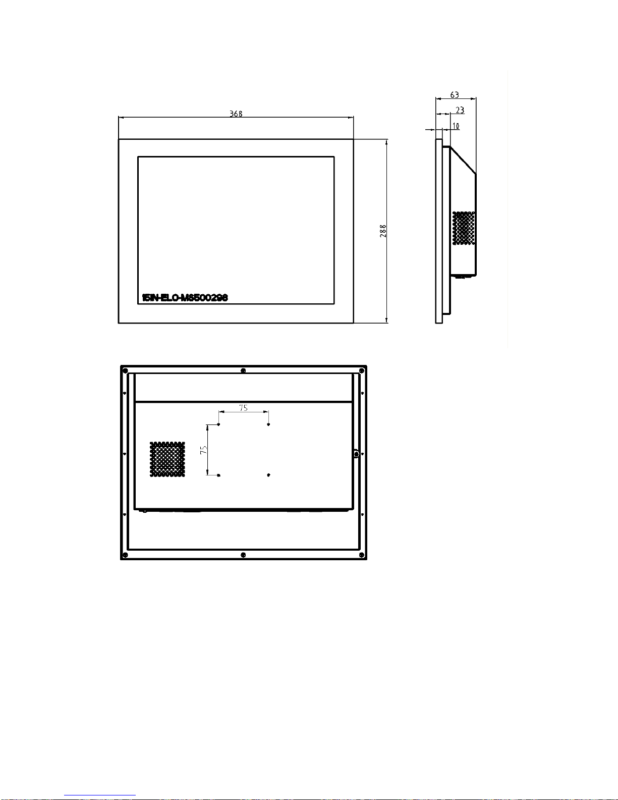
PP-9265
Page 9

PP-9260 series user’s manual ver 1.0
5
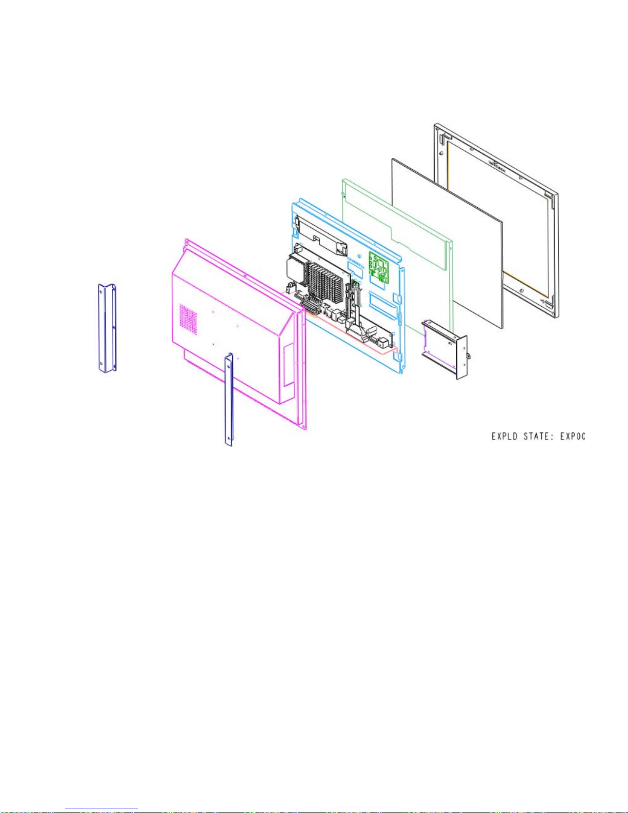
PP-9260 assemble
Please make sure that the power supply is disconnected when making any hardware changes to
PP-9265/PP-9267.
Front View :
Page 10
PP-9260 series user’s manual ver 1.0
6
Rear View :
Page 11
PP-9260 series user’s manual ver 1.0
7
Hard Disk Drive Installation
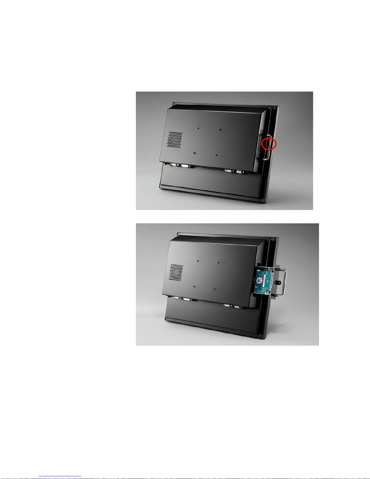
A standard PP-9265/PP-9267 comes without a hard disk drive (HDD), unless it is pre-requested.
1. Turn off power and remove power cable from main unit.
2. Remove the
fixed screw..
3. Draw the tray
out and install
the 2.5” SATA
HDD with PCB
facing backward.
Page 12
PP-9260 series user’s manual ver 1.0
8
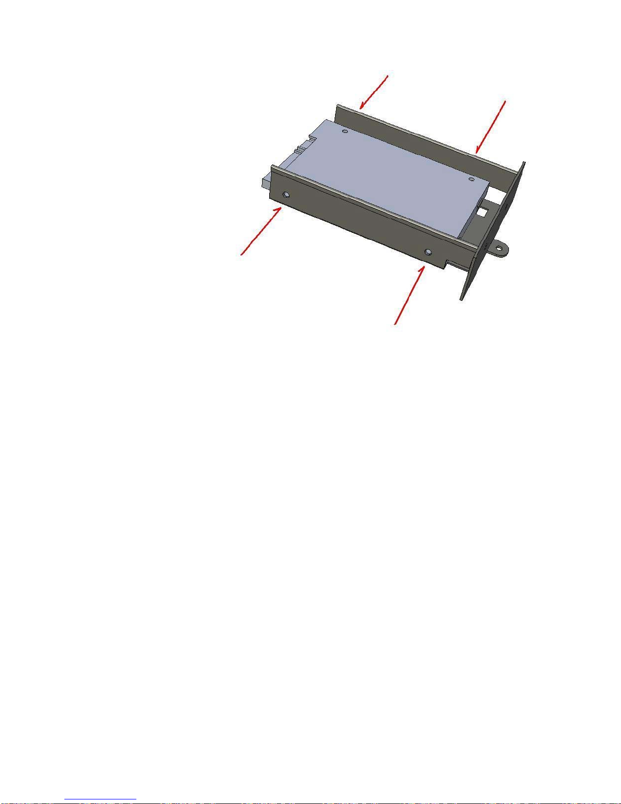
4. Fixed HDD by
four M3x5
screws
Page 13

PP-9260 series user’s manual ver 1.0
9
CChhaapptteerr 22
SSooffttwwaarree SSeettuup
p
Windows XP installation
Installing Windows XP can be performed on the PP-9265/PP-9267 quite simply
Items required:
An USB CDROM drive
1. Attach the USB CDROM drive to PP-9265/PP-9267.
2. In the CMOS setup “Advanced Chipset setup” change the item “USB Device Legacy
Support” to “All Devices” this will allow booting from any USB bootable device.
3. Power on and modify CMOS BIOS settings to enable the USB CDROM to be the first
bootable device (see CMOS setup in the motherboard manual)
4. Insert the XP CDROM disk into the drive
5. Reboot the system
6. The PP-9265/PP-9267 will boot from CDROM drive and automatically start the setup
programs
7. Follow the onscreen instructions for normal installation of 2K or XP
Page 14

PP-9260 series user’s manual ver 1.0
10
Device Driver Installation
PP-9265/PP-9267 comes with a variety of drivers for different operating systems.
You will find 1 CD with PP-9265/PP-9267.
The CD has all the necessary drivers to setup PP-9265/PP-9267.
Driver installation sequence:
Chipset (should be the first step) -> Graphics -> Ethernet -> Audio-> TouchScreen
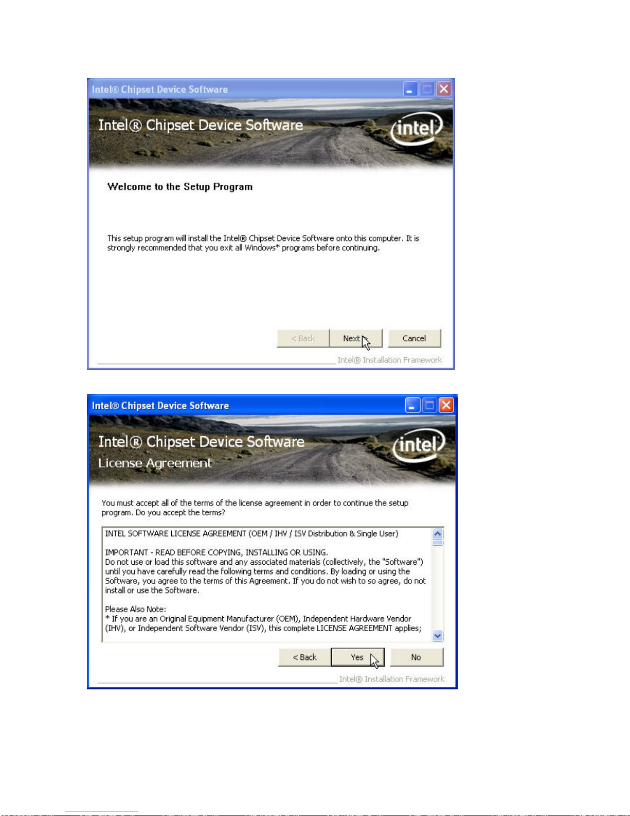
Intel Chip Set Driver Installation for Windows XP Operating Systems
1. Insert the CD into your CD ROM Drive.
2. Locate D:\Driver\chipset folder
3. Double click infinst_autol.exe
Page 15
PP-9260 series user’s manual ver 1.0
11
4. Click Next.
5. Read the License Agreement and click Yes.
Page 16
PP-9260 series user’s manual ver 1.0
12
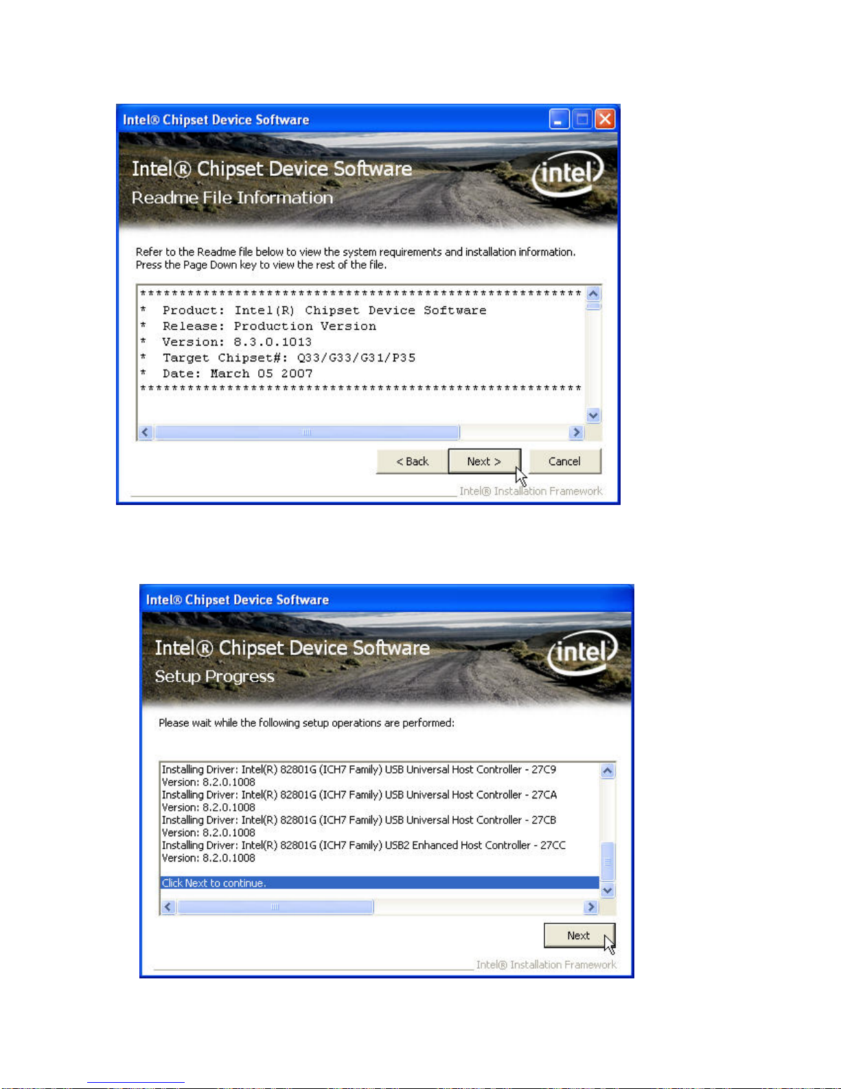
6. Click Next and finished the drivers for the Intel Chip set will install.
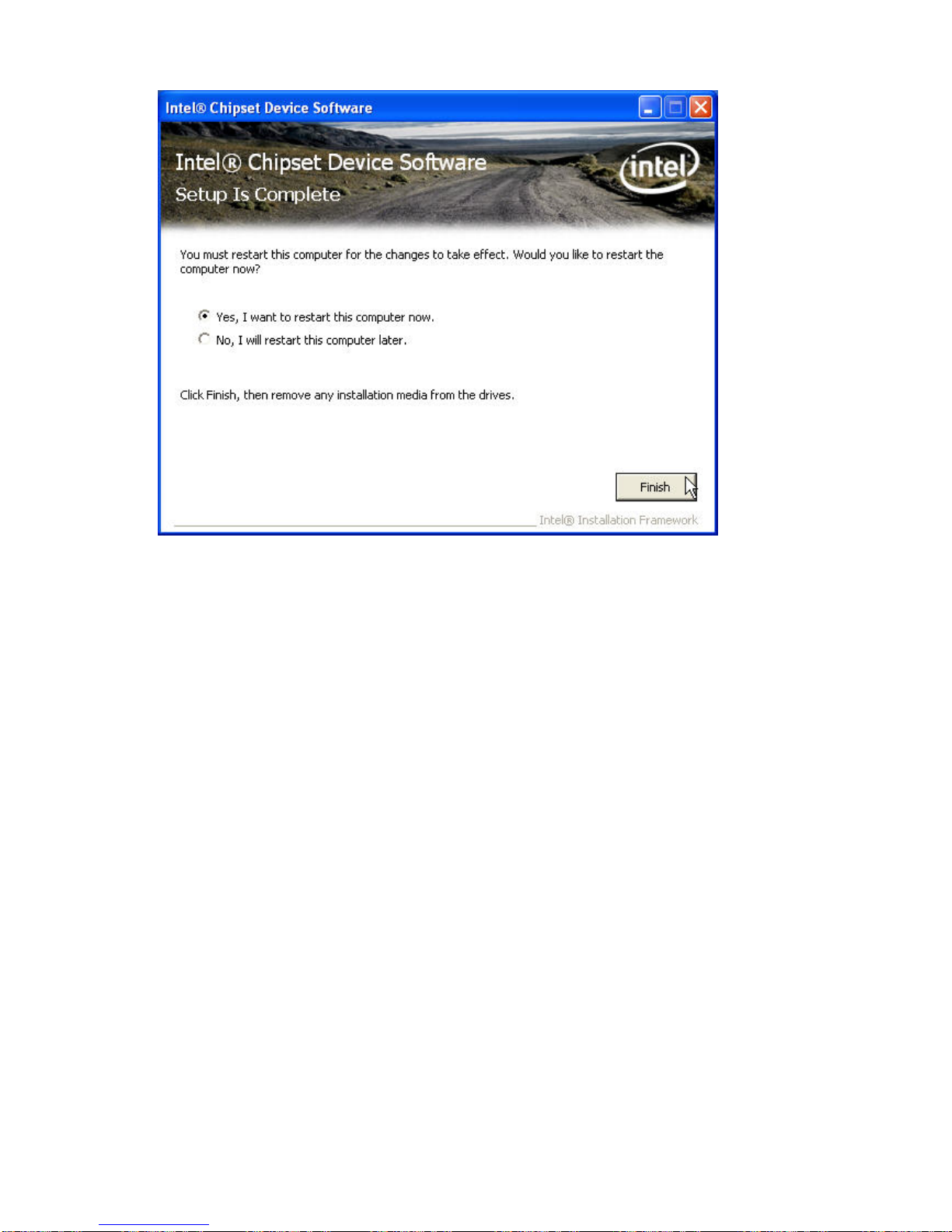
7. When the 'Setup COMPLETE' message appears click Finish to restart your computer.
Page 17
PP-9260 series user’s manual ver 1.0
13
Page 18
PP-9260 series user’s manual ver 1.0
14
Graphics Driver Installation
PP-9260 series uses only one chipset “Intel 945GME” that is capable of driving a single or dual
panel display. Only one driver needs to be installed.
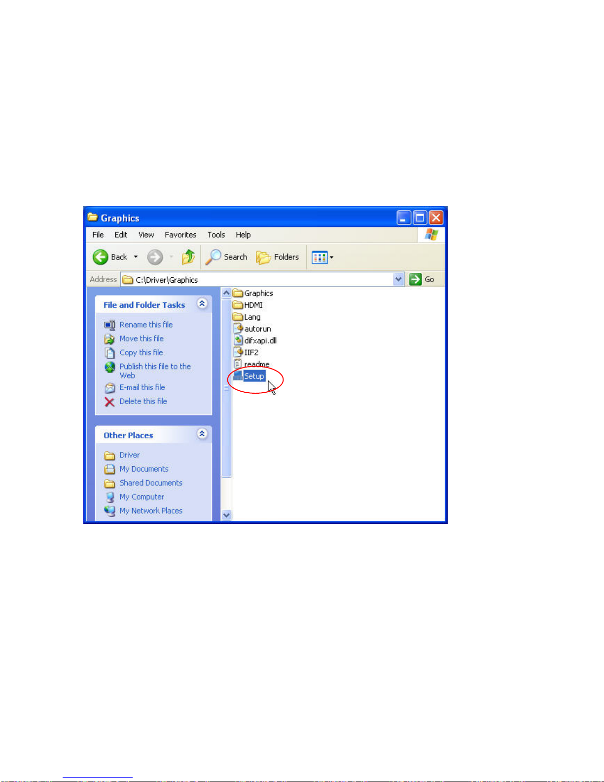
945GME GraphicsM driver installation Windows 2000 & XP
1. Open D:\Driver\Graphics folder
2. Run setup.exe
Page 19

PP-9260 series user’s manual ver 1.0
15
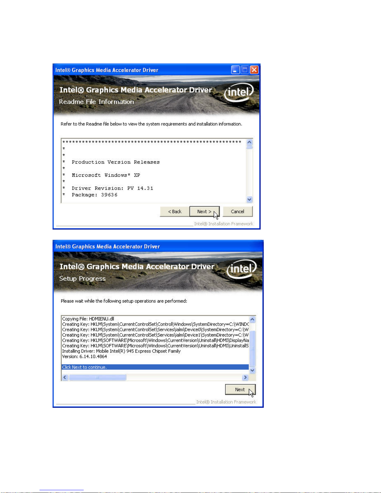
3. Select Next to continue.
4. Read the License Agreement and click Yes.
Page 20
PP-9260 series user’s manual ver 1.0
16
5. Click Next to continue the setup procedures and click Finish to complete the installation.
(Need to restart computer to active the settings)
Page 21

PP-9260 series user’s manual ver 1.0
17
Page 22
PP-9260 series user’s manual ver 1.0
18
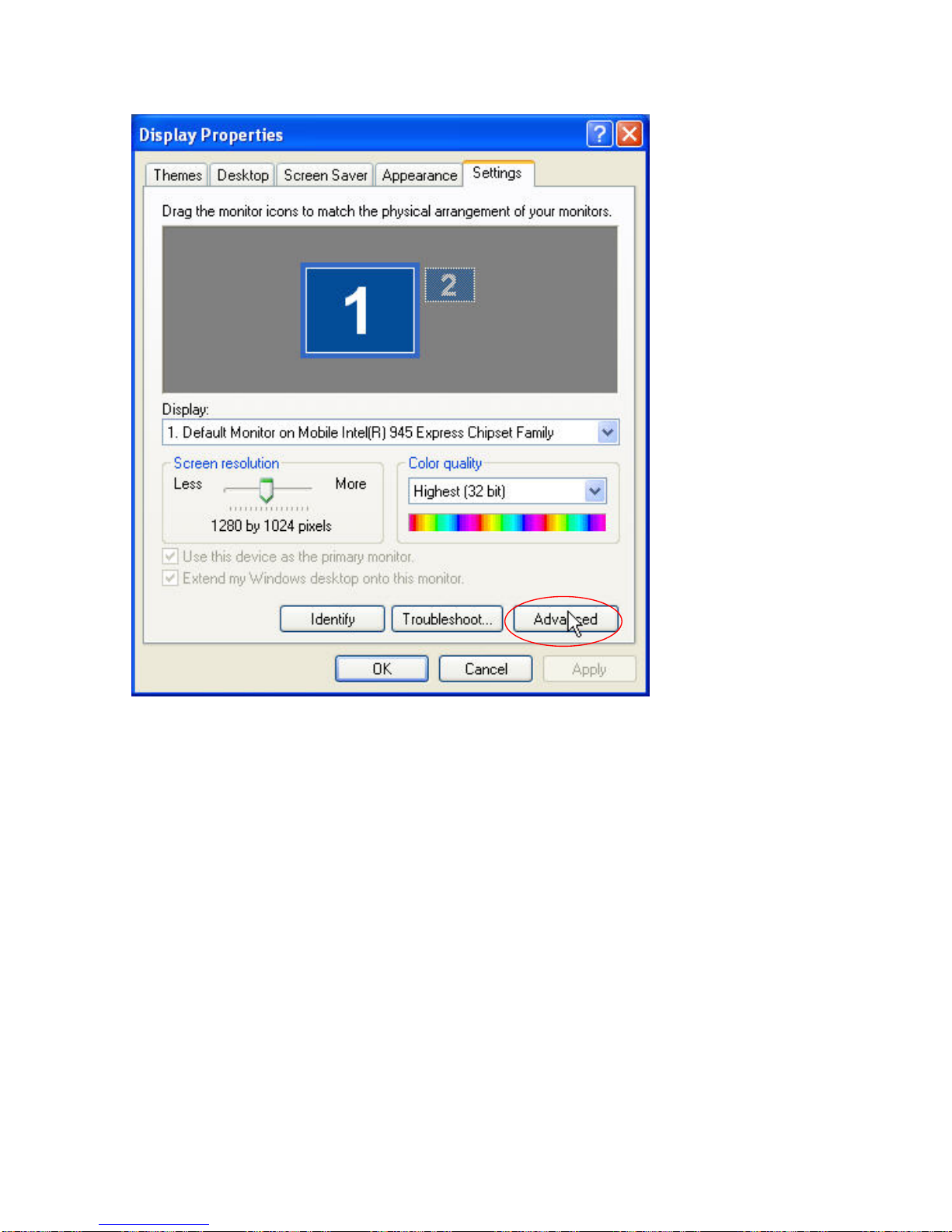
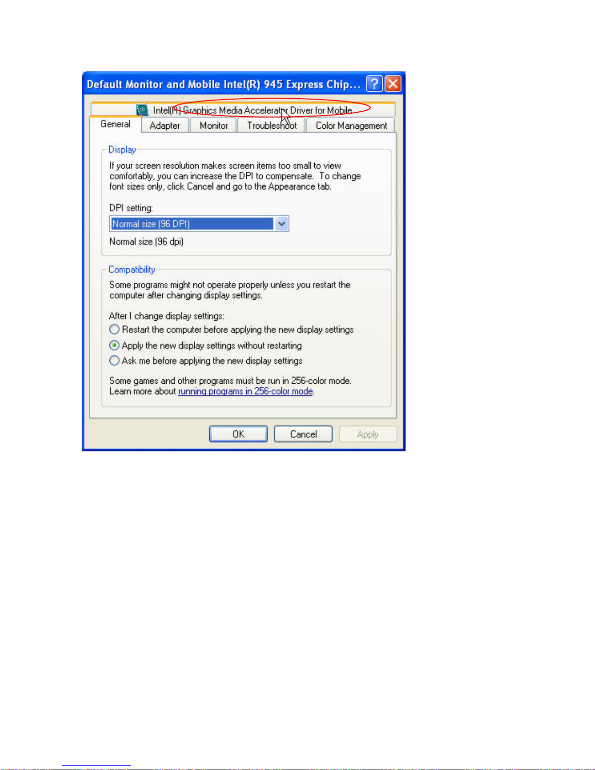
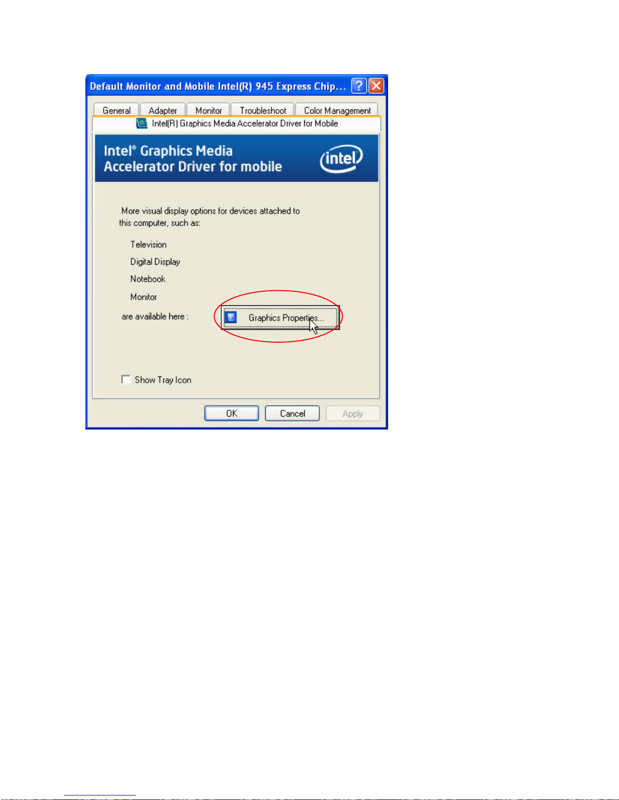
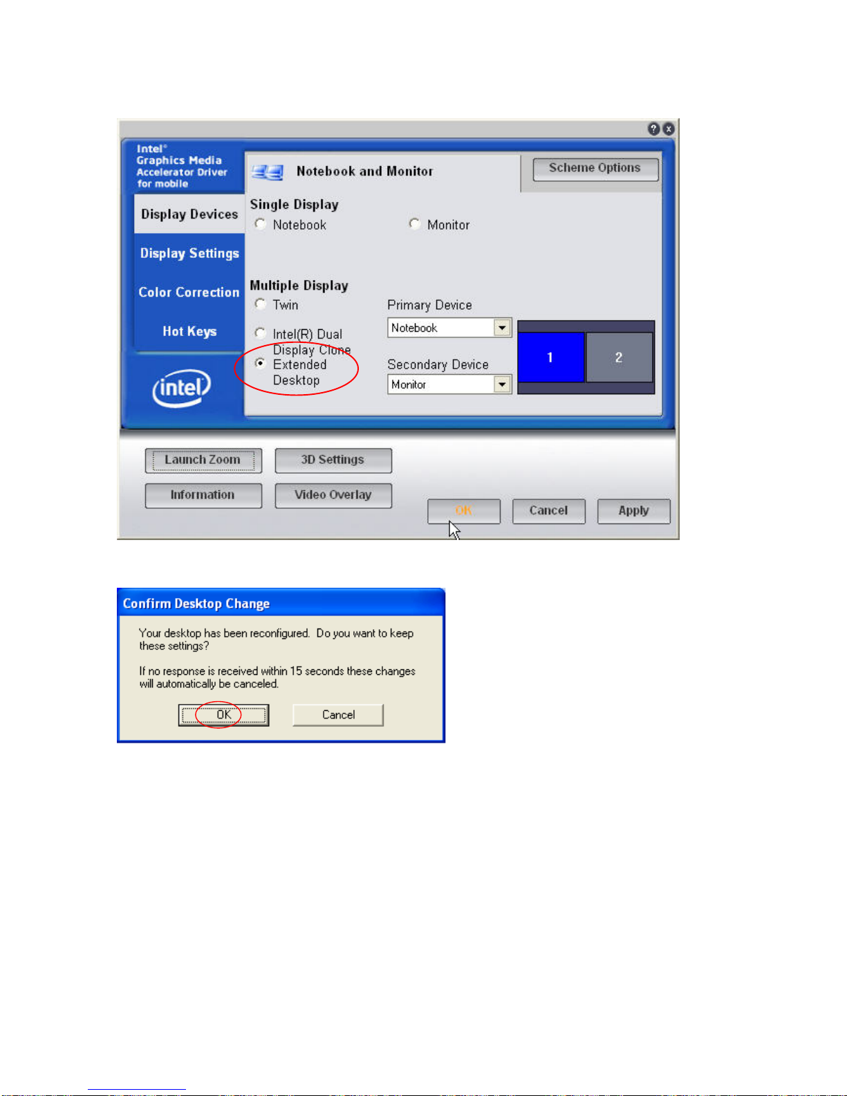
Enable second Display
After you have installed the Graphics driver you must adjust the settings for the second display
.
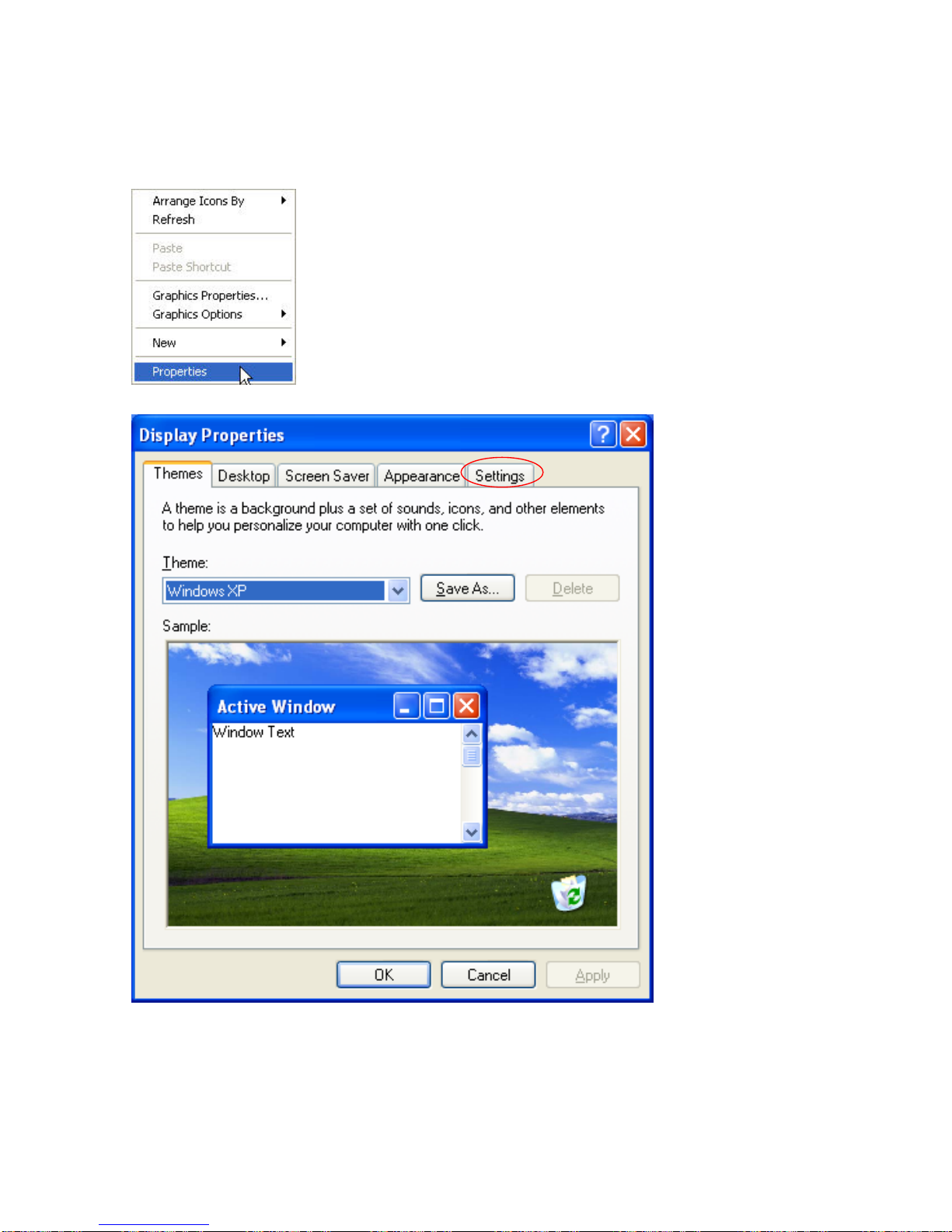
5. Right click your mouse anywhere on the desktop then click properties.
6. Click the settings tab.
Page 23
PP-9260 series user’s manual ver 1.0
19
7. Click Advanced.
Page 24
PP-9260 series user’s manual ver 1.0
20
8. Click Intel(R) Graphics. Media Accelerator Driver For Mobile
Page 25
PP-9260 series user’s manual ver 1.0
21
9. Click Graphics Properties.
Page 26
PP-9260 series user’s manual ver 1.0
22
10. Click Extended Desktop and select Notebook for primary device, monitor for secondary
device.
11. Click OK.
12. Select the second LCD panel. This is done either by clicking on the number 2 or selecting
from the dropdown menu.
For the second LCD panel make sure that Extend my Windows desktop onto this monitor is
selected.
13. Click Apply then click OK to finish the settings.
Note. During boot sequence “No Sync” will appear on the second LCD panel.
The boot sequence can take a minute or so when a second LCD panel is installed.
Page 27
PP-9260 series user’s manual ver 1.0
23
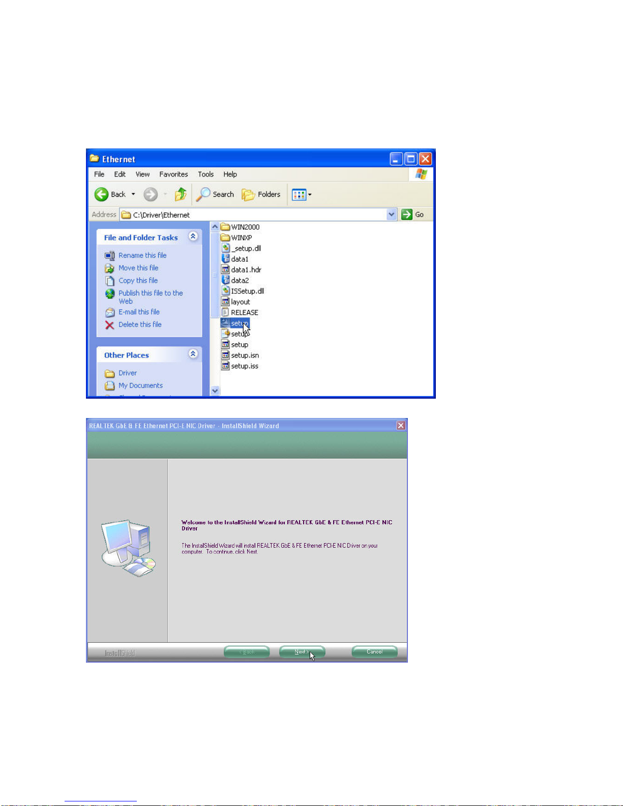
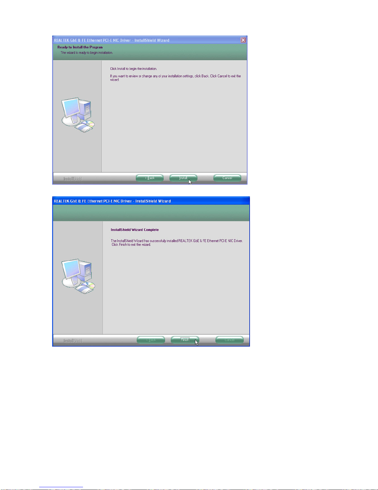
Ethernet Driver Installation
1. Open D:\Driver\Ethernet folder
2. Run setup.exe and system will automatically install the driver
3. Click Finish
Page 28
PP-9260 series user’s manual ver 1.0
24
Page 29
PP-9260 series user’s manual ver 1.0
25
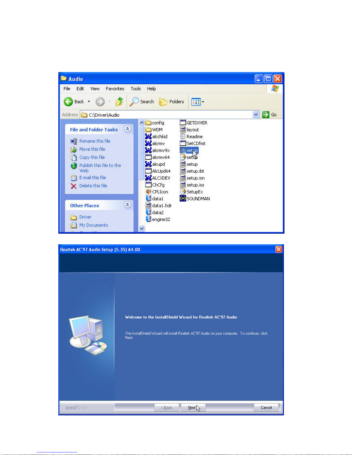
Audio Driver Installation
1. Open D:\Driver\Audio
2. Double click Setup.exe. and system will automatically install the driver
3. Click Next to continue
Page 30
PP-9260 series user’s manual ver 1.0
26
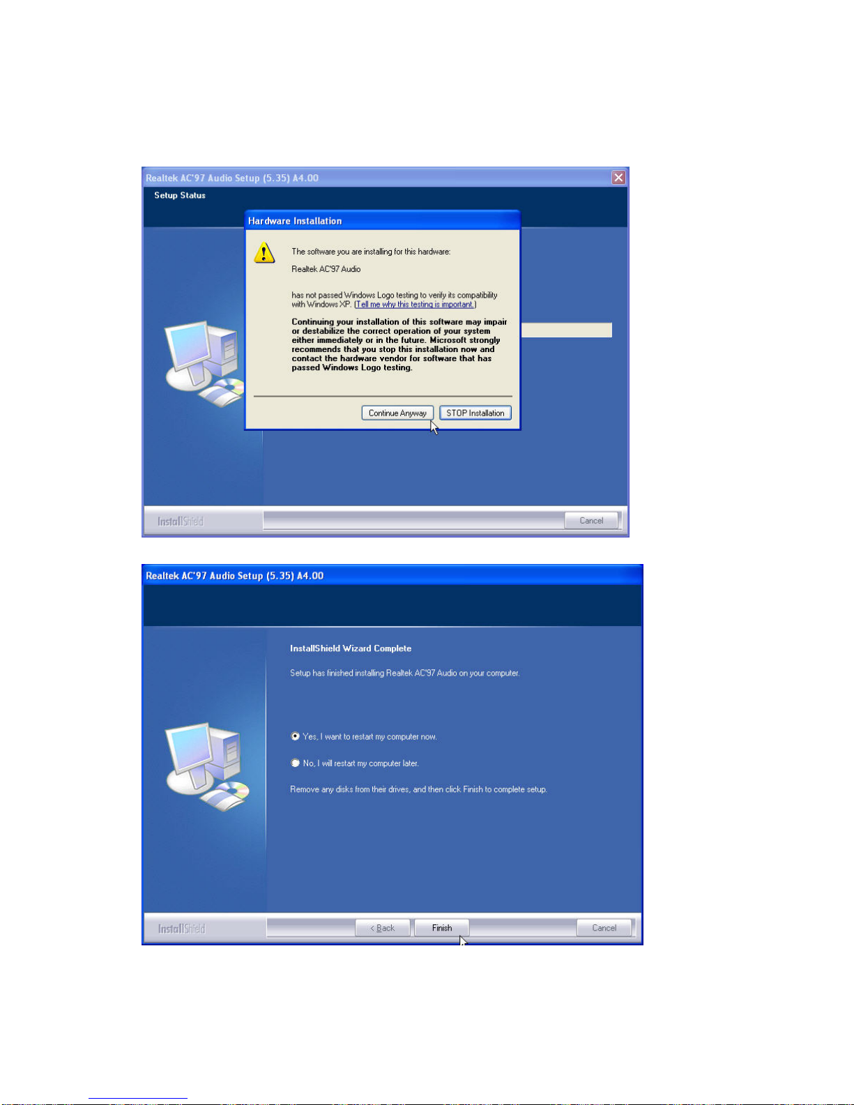
4. Click Continue Anyway
Note: For XP If you receive this warning message, please click Continue Anyway.
5. Click Finish
Page 31
PP-9260 series user’s manual ver 1.0
27
TouchScreen Driver Installation (Elo Resistive/IR touch )
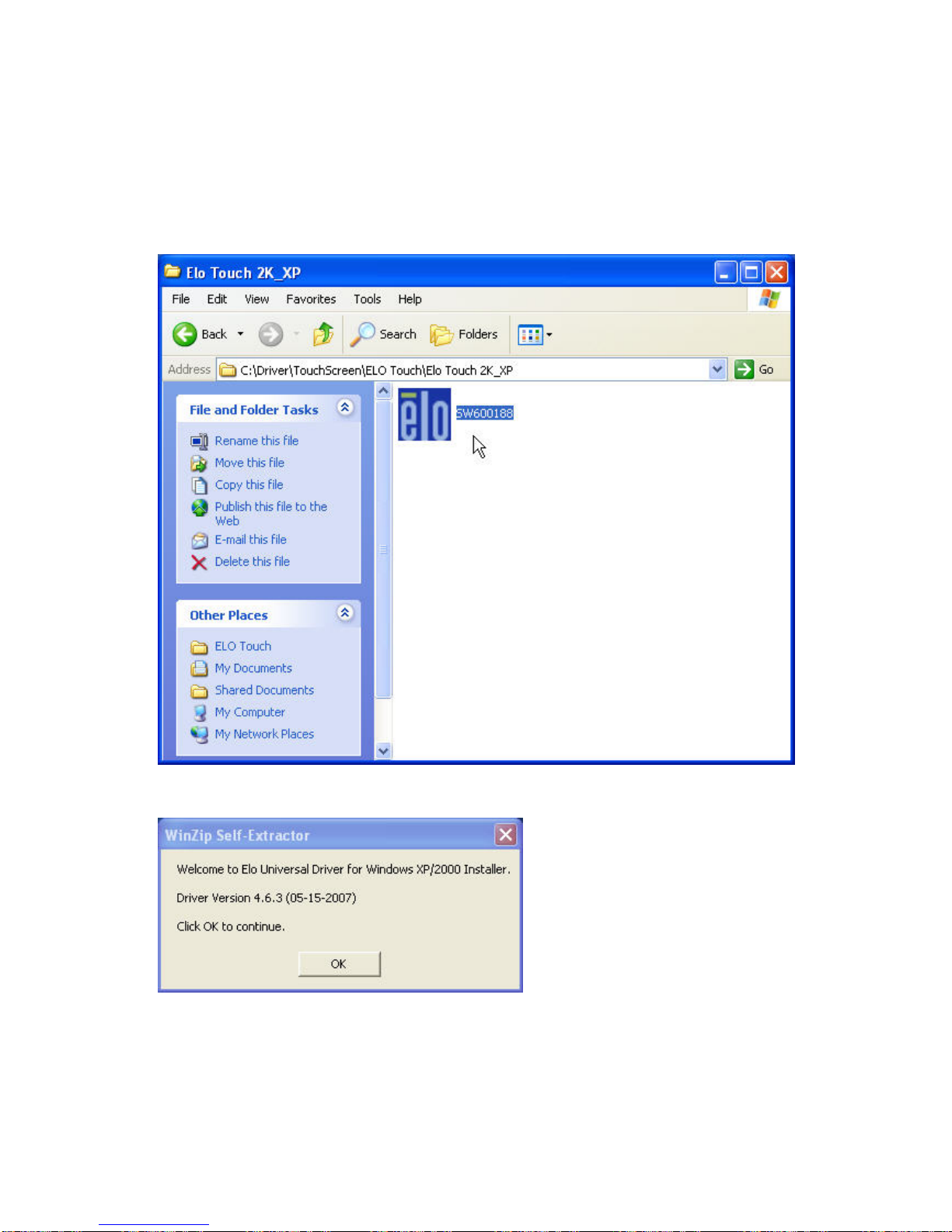
1. Locate D:\Utility\TouchScreen\ELO Touch
2. Select the Elo Touch 2K_XP folder
3. Run SW600188.exe
4. Click OK
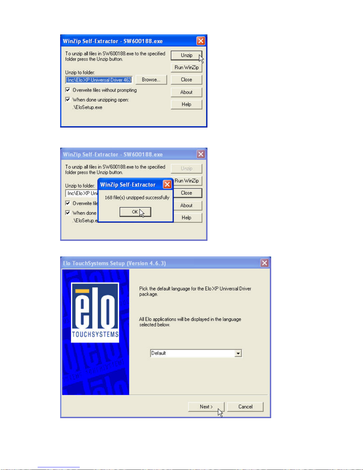
5. Click “Unzip” to continue.
Page 32
PP-9260 series user’s manual ver 1.0
28
6. Click “OK”
7. Click “Default” and Next
Page 33
PP-9260 series user’s manual ver 1.0
29
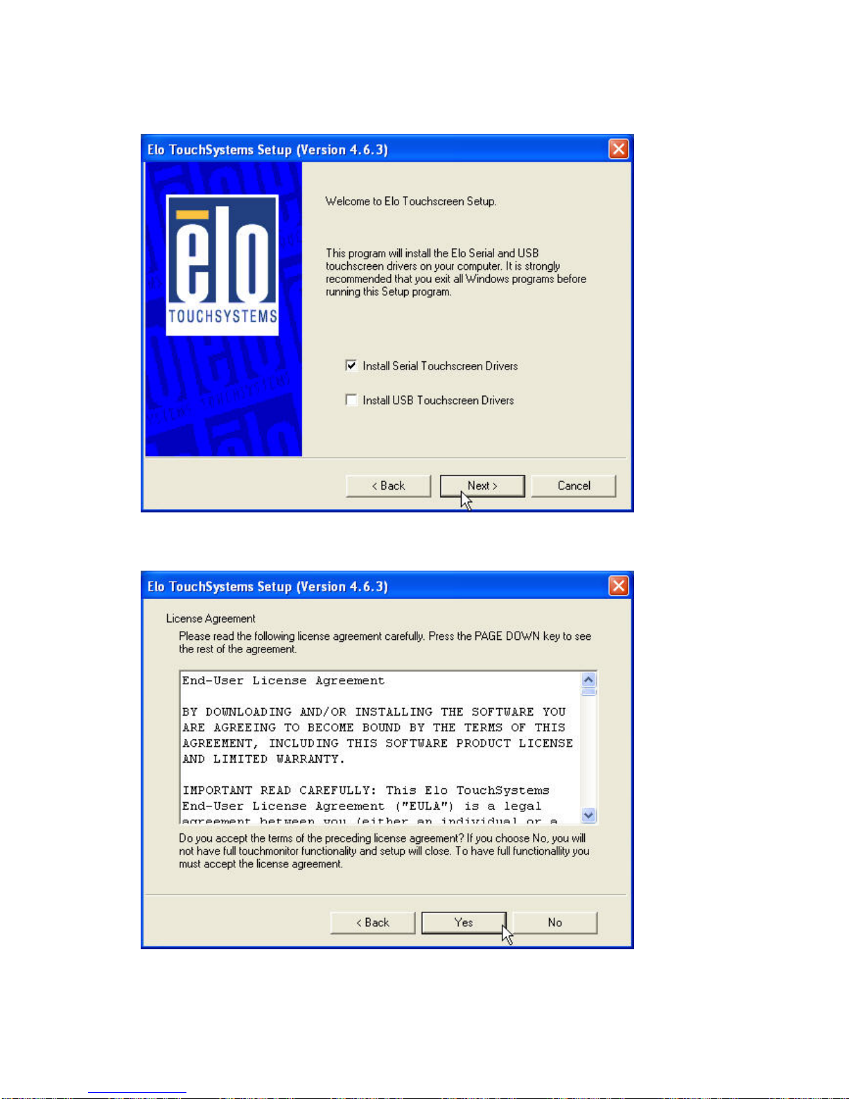
8. Select “Install Serial Touchscreen Drivers” and click Next
9. Click Yes
Page 34
PP-9260 series user’s manual ver 1.0
30
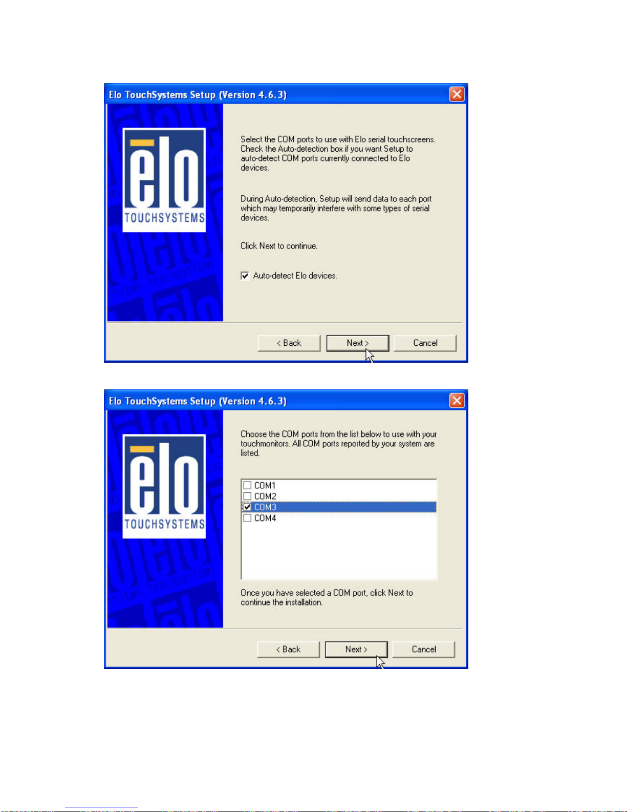
10. Select “Auto-detect Elo drivers” and Click Next
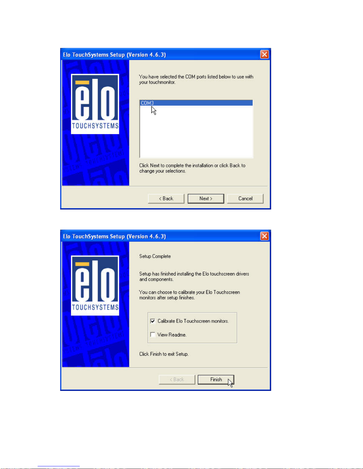
11. Select COM 3 and Next .
Page 35
PP-9260 series user’s manual ver 1.0
31
12. Click once on COM 3 and click NEXT
13. Click Finish and continue the procedure of Calibrate Elo Touchscreen
Page 36
PP-9260 series user’s manual ver 1.0
32
ELO Control Panel
This section explains the options in the ELO control Panel.
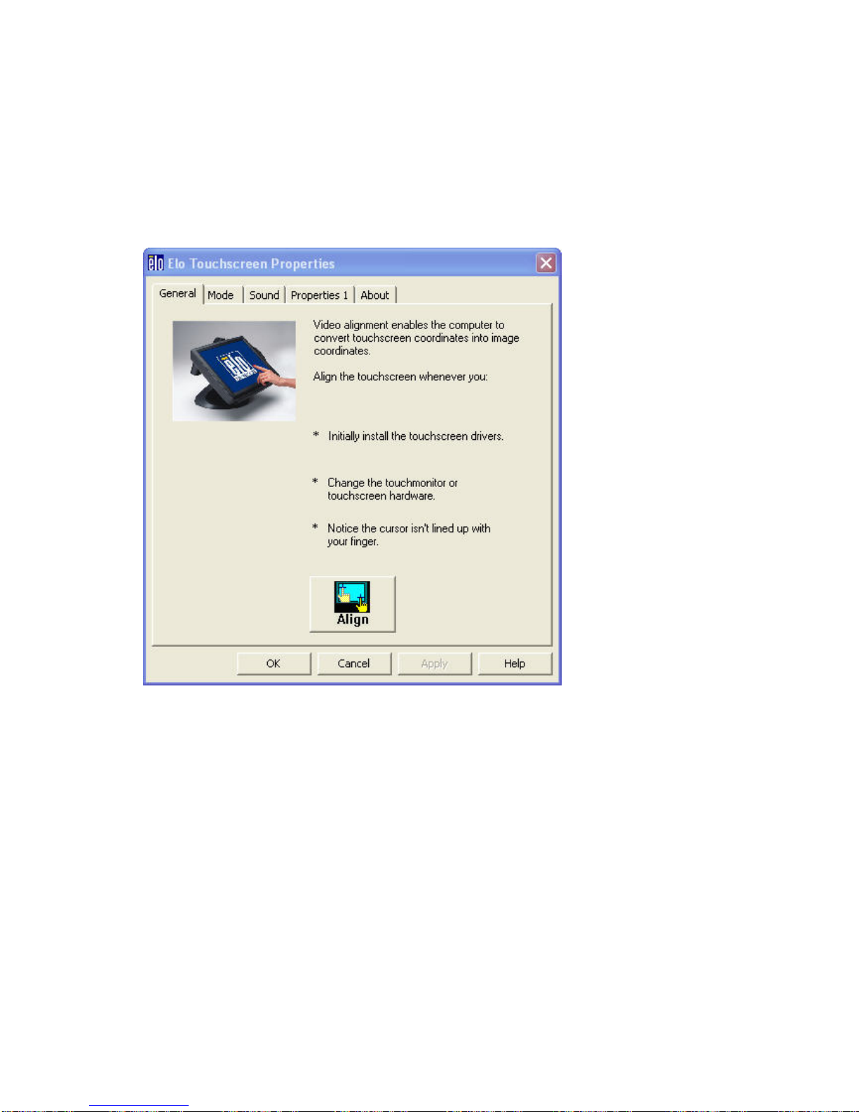
General tab
The general tab allows you to:
• Change the COM port your touch screen is set to.
• Calibrate the touch screen with the Align button.
Page 37
PP-9260 series user’s manual ver 1.0
33
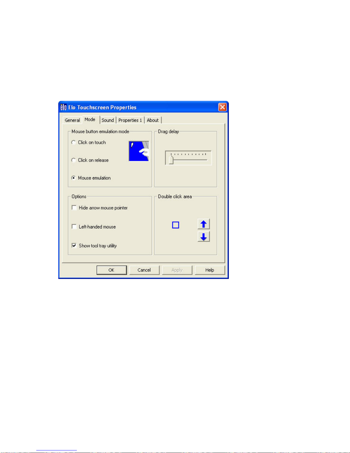
Mode tab
The Buttons tab allows you to:
• Adjust all mouse emulation controls.
• Change cursor properties
• Enable or disable right mouse button utility.
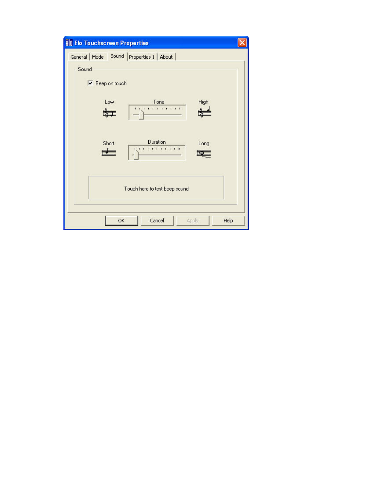
Sound tab
The Sound tab allows you to:
• To change sound properties for ELO touch tools.
Page 38
PP-9260 series user’s manual ver 1.0
34
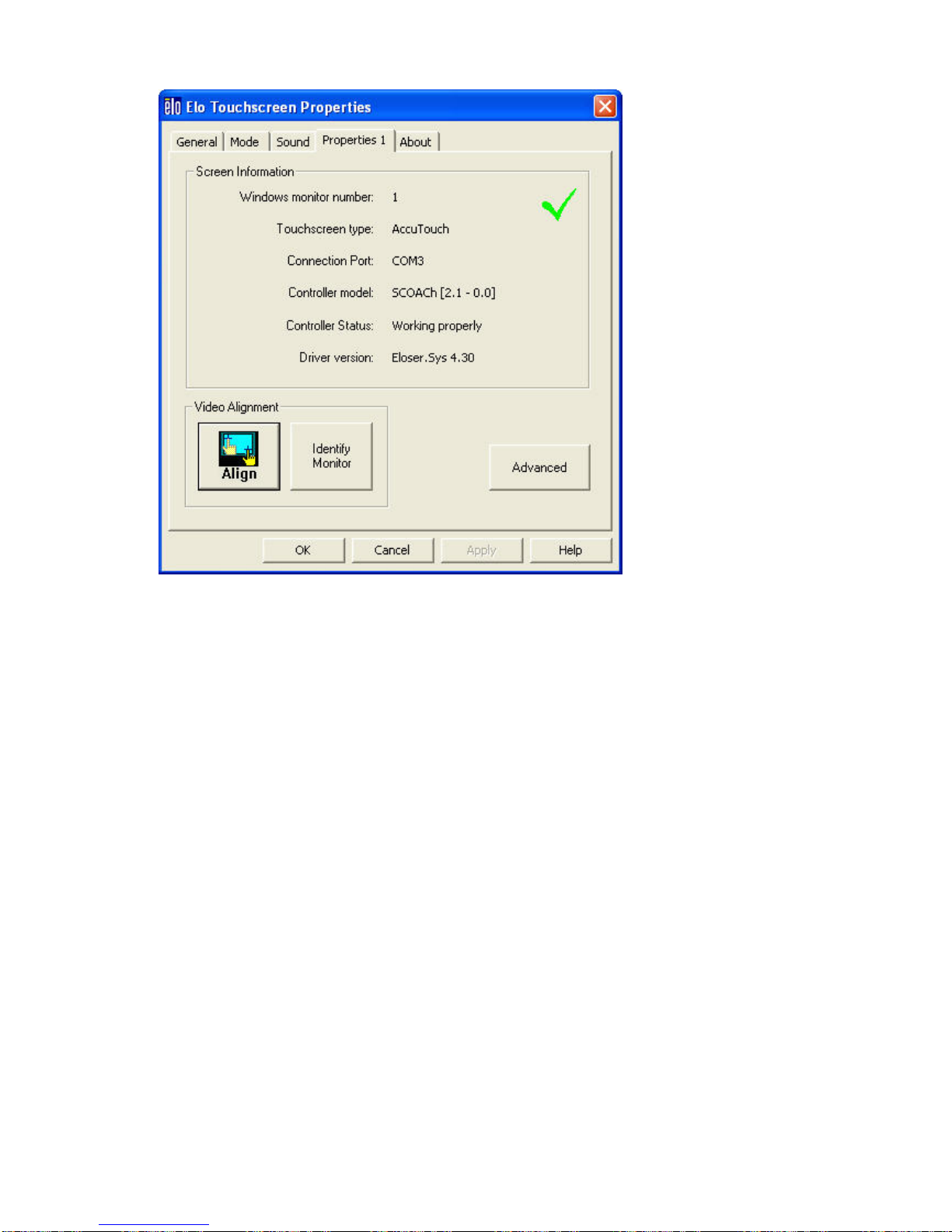
Properties tab
The Diagnostics tab allows you to:
• View Controller Information.
Page 39
PP-9260 series user’s manual ver 1.0
35
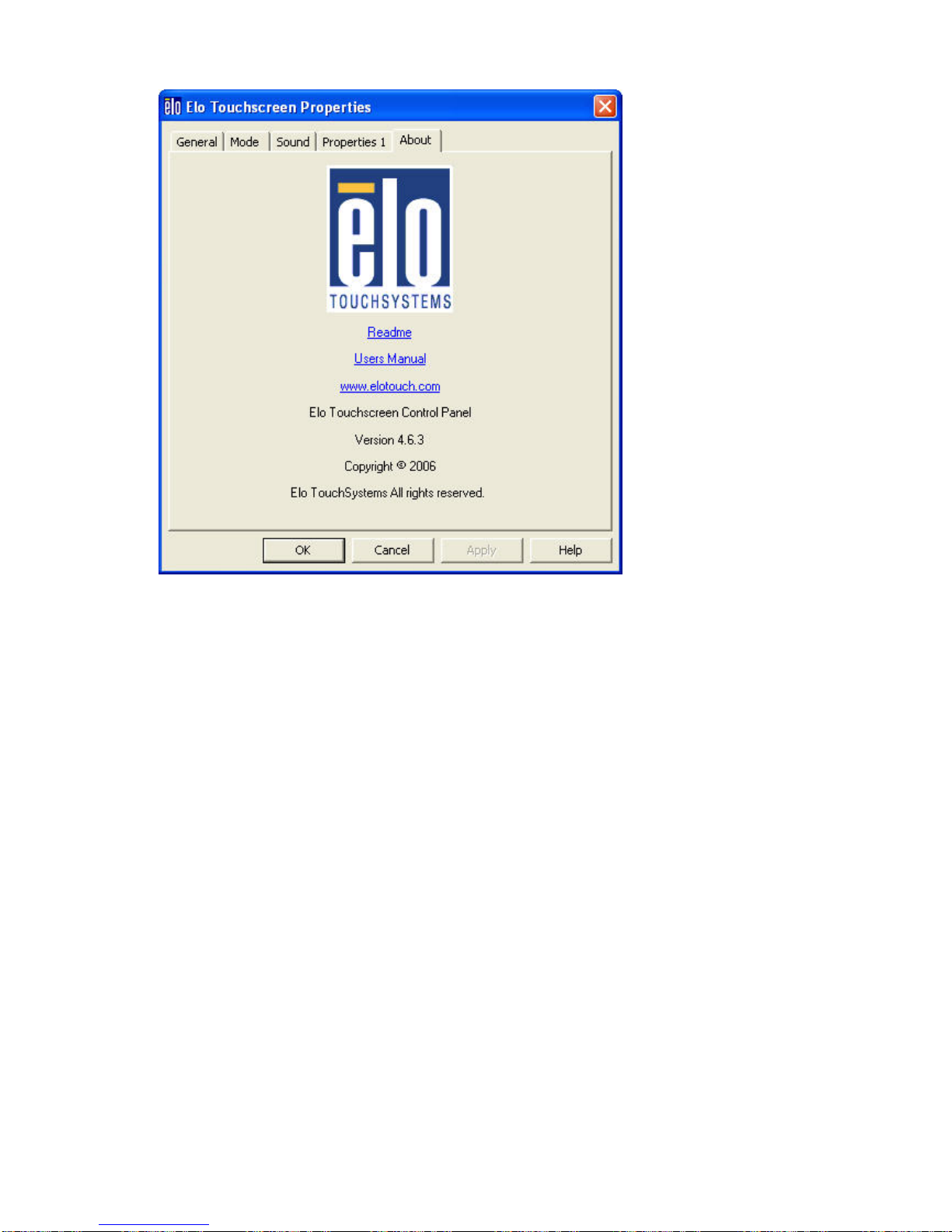
About tab
The About tab displays Information about ELO Touch systems
Page 40
PP-9260 series user’s manual ver 1.0
36
Page 41

PP-9260 series user’s manual ver 1.0
37
TouchKit Tools Installation
Driver Locate in D:\Driver\TOUCHSCREEN\TouchKit(Fujitsu)\Windows 20000 XP
.
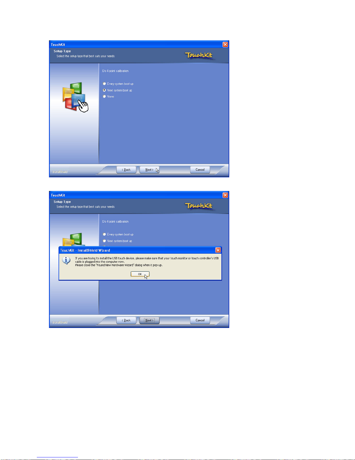
1. Open Setup.exe
2. Click Next
Page 42
PP-9260 series user’s manual ver 1.0
38
3. Click Next
4. Click OK
Page 43

PP-9260 series user’s manual ver 1.0
39
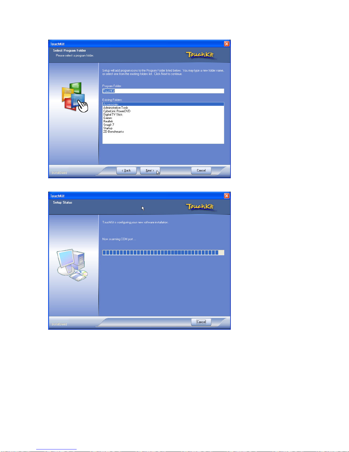
5. Click Next
6. Click Next
Page 44
PP-9260 series user’s manual ver 1.0
40
7. Click Next
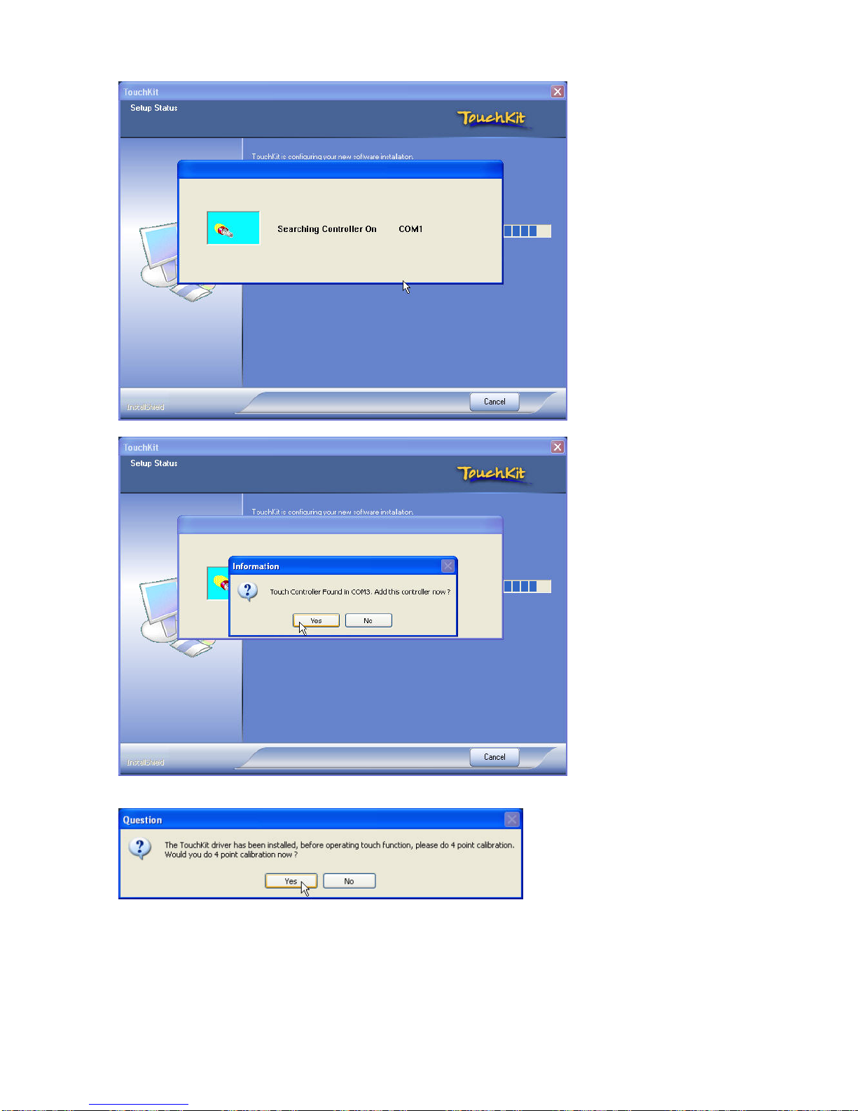
8. Auto scan the COM port and select COM 3
Page 45
PP-9260 series user’s manual ver 1.0
41
9. Installation finished and do 4 point calibration, Click Yes
Page 46
PP-9260 series user’s manual ver 1.0
42
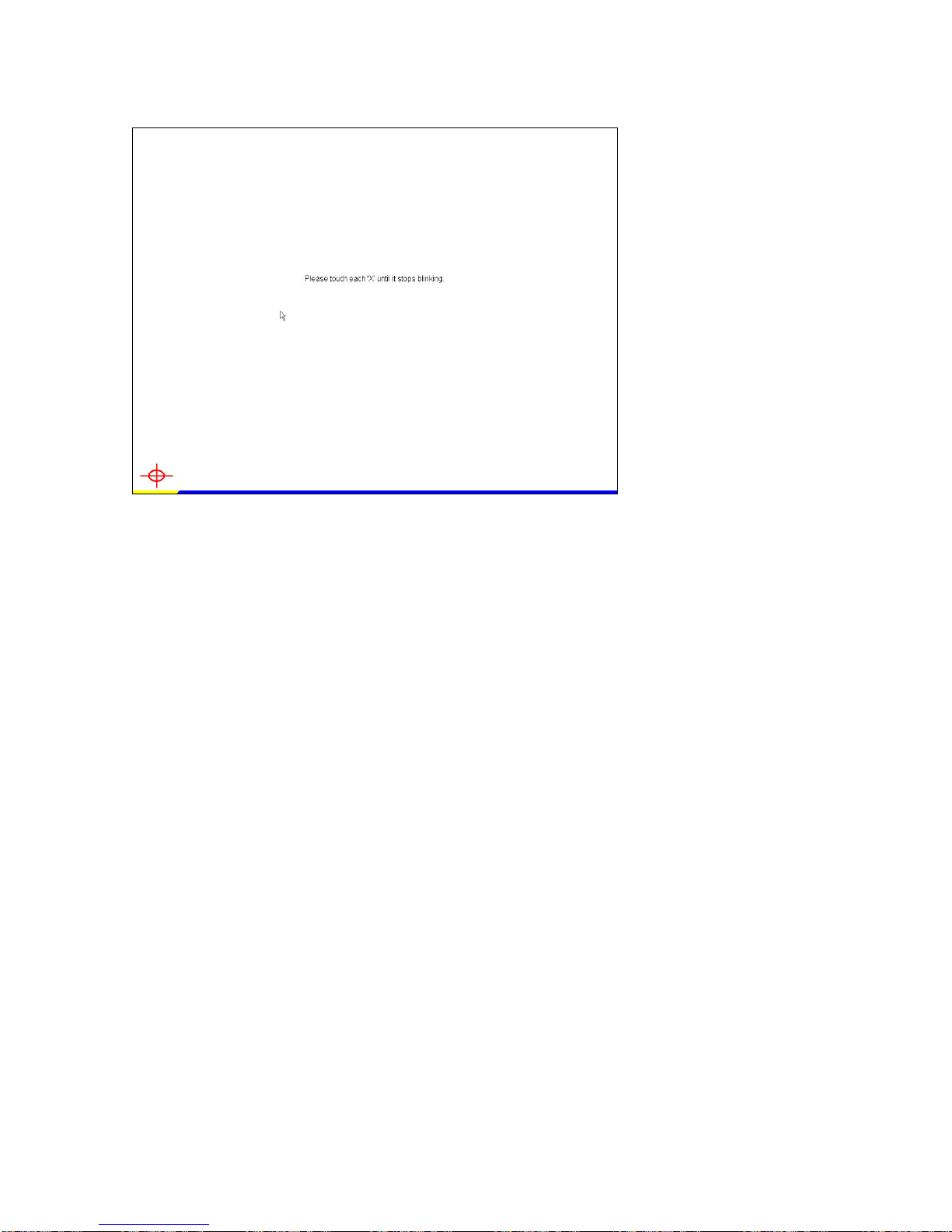
10. Calibrations
Page 47
PP-9260 series user’s manual ver 1.0
43
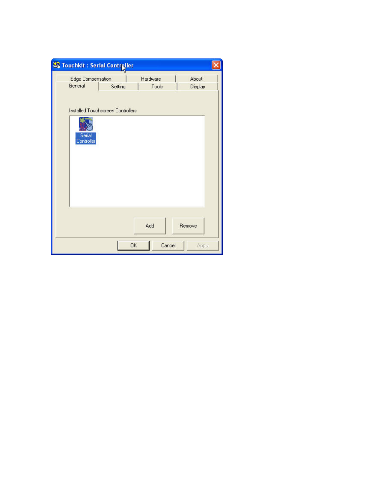
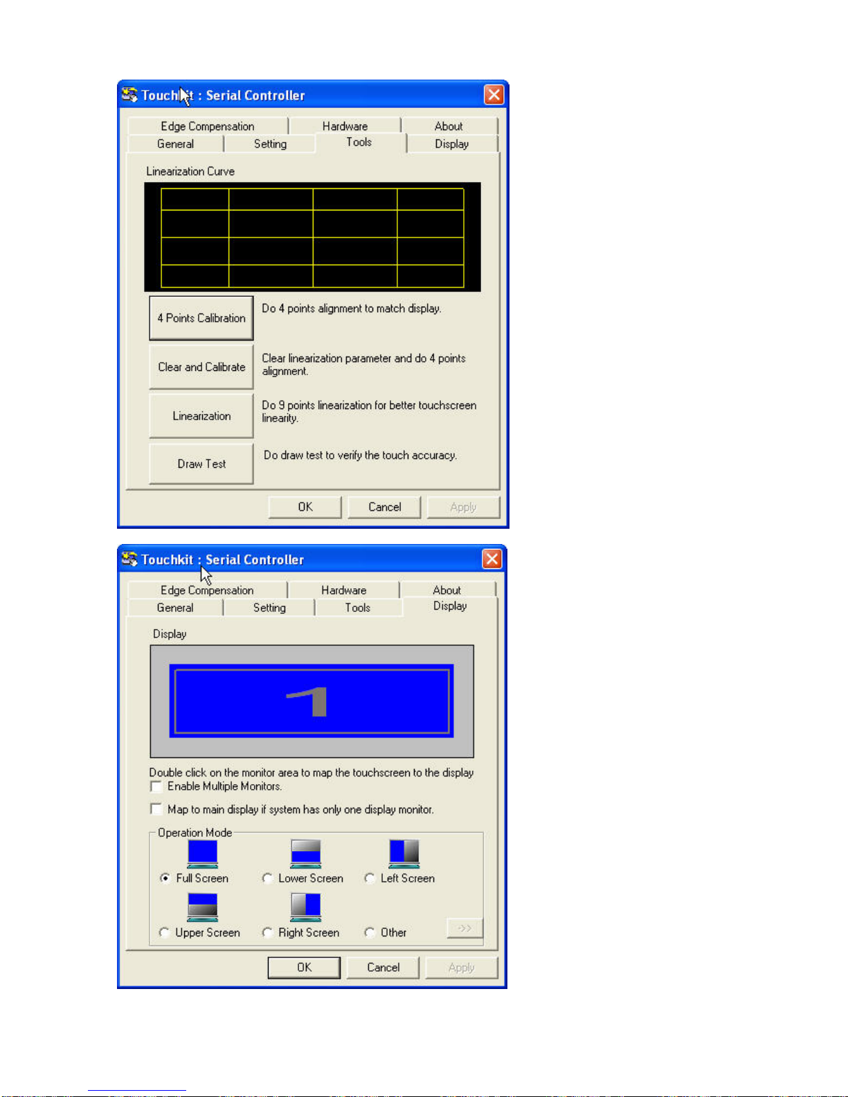
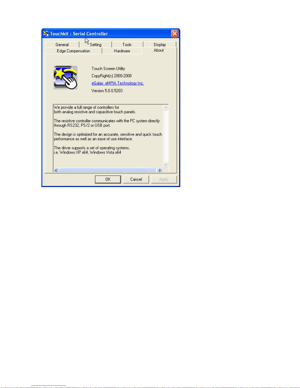
TouchKit Control Panel
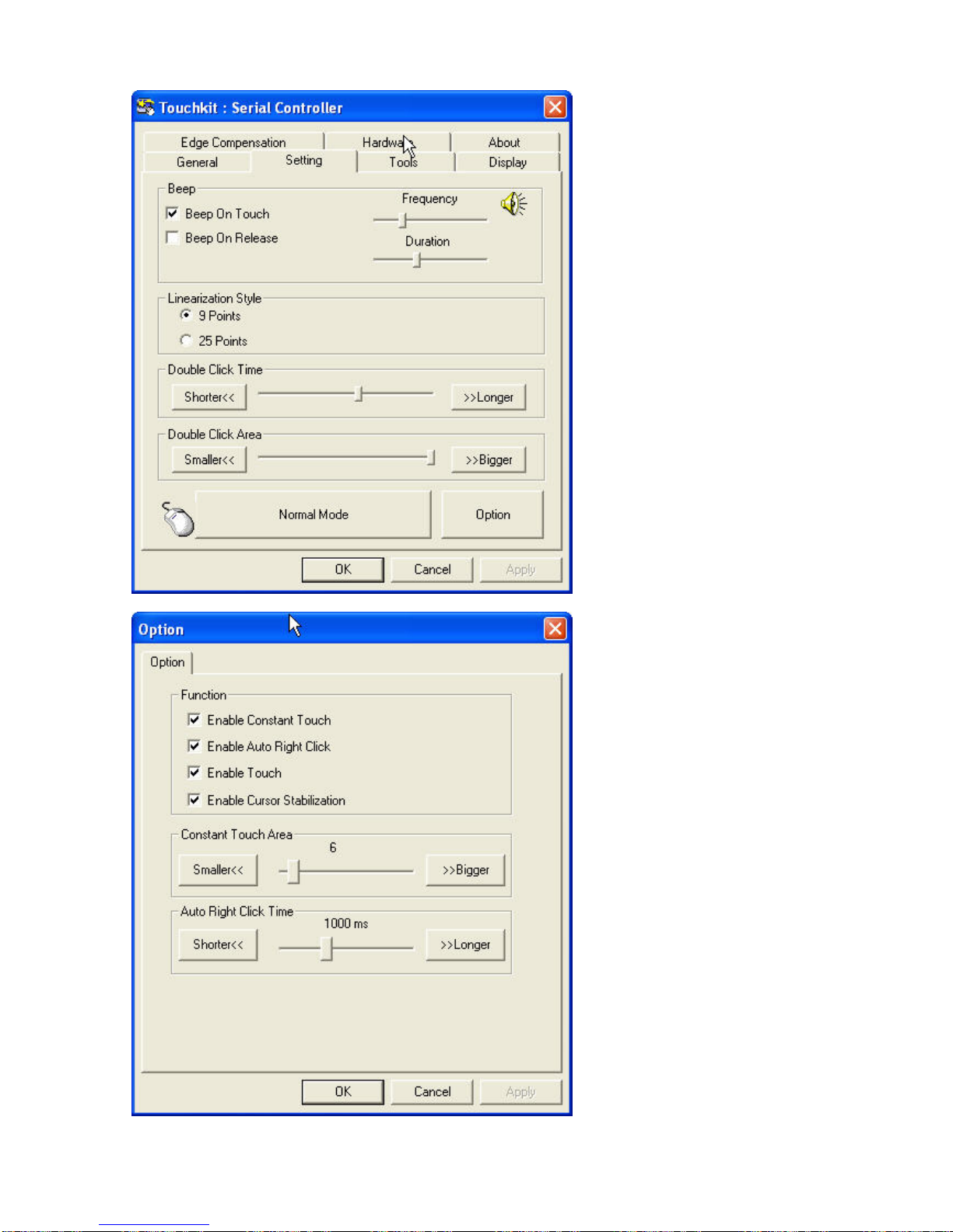
This section explains the different options in the TouchKit control Panel.
Page 48
PP-9260 series user’s manual ver 1.0
44
Page 49
PP-9260 series user’s manual ver 1.0
45
Page 50

PP-9260 series user’s manual ver 1.0
46
Page 51
PP-9260 series user’s manual ver 1.0
47
Page 52
PP-9260 series user’s manual ver 1.0
48
CChhaapptteerr 33
SSppeecciiffiiccaattiioonnss
SSyysstteemm ssppeecciiffiiccaattiioonnss
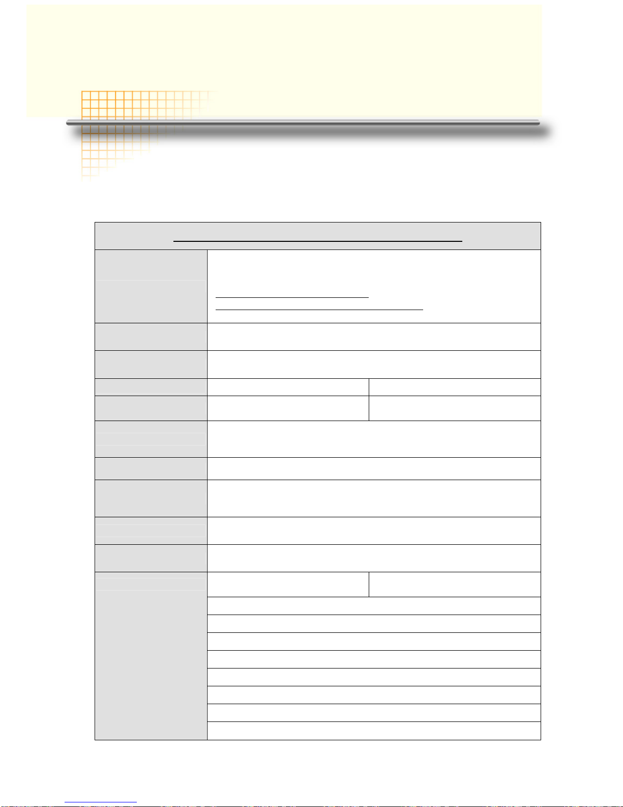
PP9620 series Panel PC specifications
CPU
Socket M (479-pin) for Intel® Core™2 Duo/Core™ Duo/Solo
667/533MHz;
Default:
Yonah Dual Core T2500 2.0 Ghz FSB 667Mhz L2 cache 2M
Yonah Single Core Celeron M 440_1.86GHz FSB 533Mhz L2 cache
1M
System Chipset Intel® 945GME + ICH7M,
System memory
1 x 200-pin DDR2 DIMM up to 2GB
Default: 512MB
Model name
PP-9267 PP-9265
LCD
17“ TFT LCD 1280x1024, 300
nits
15“ TFT LCD 1024x768, 350 nits
Display
Intel® Graphics Media Accelerator (GMA) 950
* LVDS with 18/36 bit channel mode as primary LCD display
* DVI-I connector for DVI and CRT output for secondary display
Display memory Max. up to 224MB frame buffer sharing system memory
Touch and controller
5-wire/4-wire Resistive touch (RS-232)
IR touch(RS-232)
Default: Elo 5-wire Resistive touch
HDD
One removable slide-in SATA 2.5” HDD with cables connection
Default : 80 GB
Watchdog Timer Reset supported; 255 levels
USB 2.0 x 5
Powered USB 12V x1
USB 2.0 x6
SATA-150 x2 (1 for HDD, 1 reserved for future upgrade),
RS-232 x3(COM1/2/4) with +5V/12V powered, D-sub 9 connector
RS-232 x1 pinheader for touch controller
DVI-I output for secondary display ( A DVI-VGA adaptor attached)_
Line-in, Line-out, Mic-in
Giga LAN x1
Printer port x1, D-sub 25 connector
I/O
PS/2 for Keyboard, Mouse
Page 53
PP-9260 series user’s manual ver 1.0
49
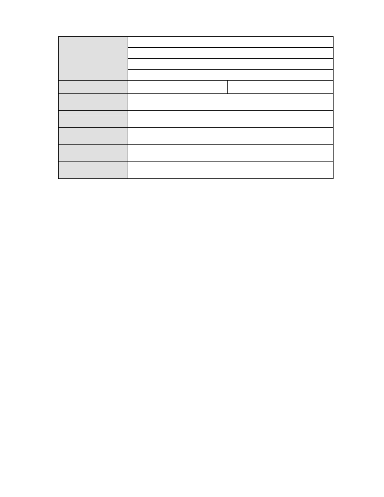
RJ-11 for digital I/O
IDE x1( 44 pin, DMA 100,reserved for DOM)
Compact Flash Type I/II socket
Power DIN 4P plug and power switch
Dimensions
403Wx325Hx68Dmm 367Wx283Hx68Dmm
Mounting
VESA standard 75mm screws holes for wall mount arm
Panel mount bracket x2 (depends on customer’s requirement)
Housing Heavv duty steel, black color
EMI safety CE, FCC,RoHS
Weight 6.5 kg
Power Supply External 12V adaptor 150W,, AC 90~230 50~60Hz universal input
Page 54
PP-9260 series user’s manual ver 1.0
50
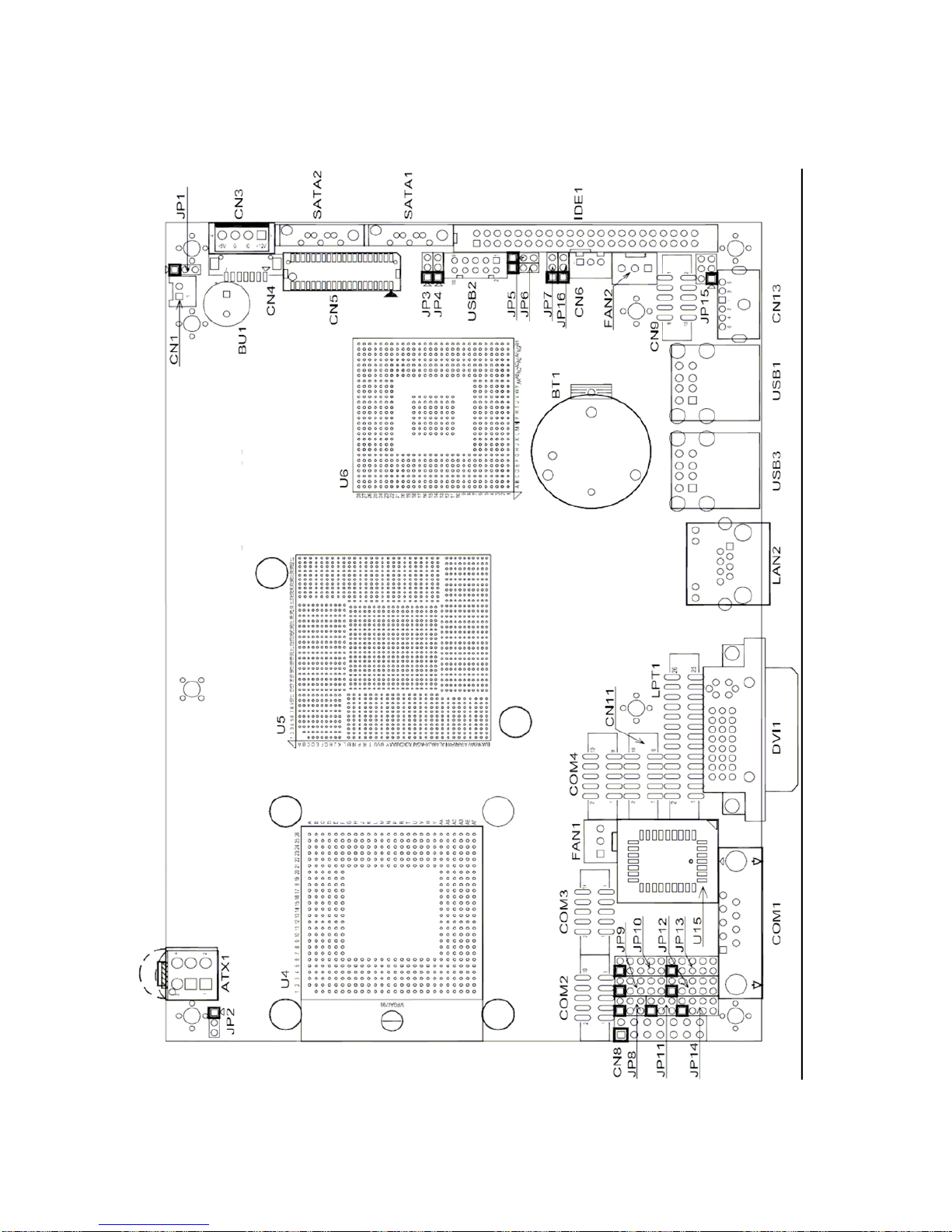
Motherboard configurations
This chapter describes the jumpers/connectors of
EP-830F
motherboard.
Motherboard layout
Page 55
PP-9260 series user’s manual ver 1.0
51
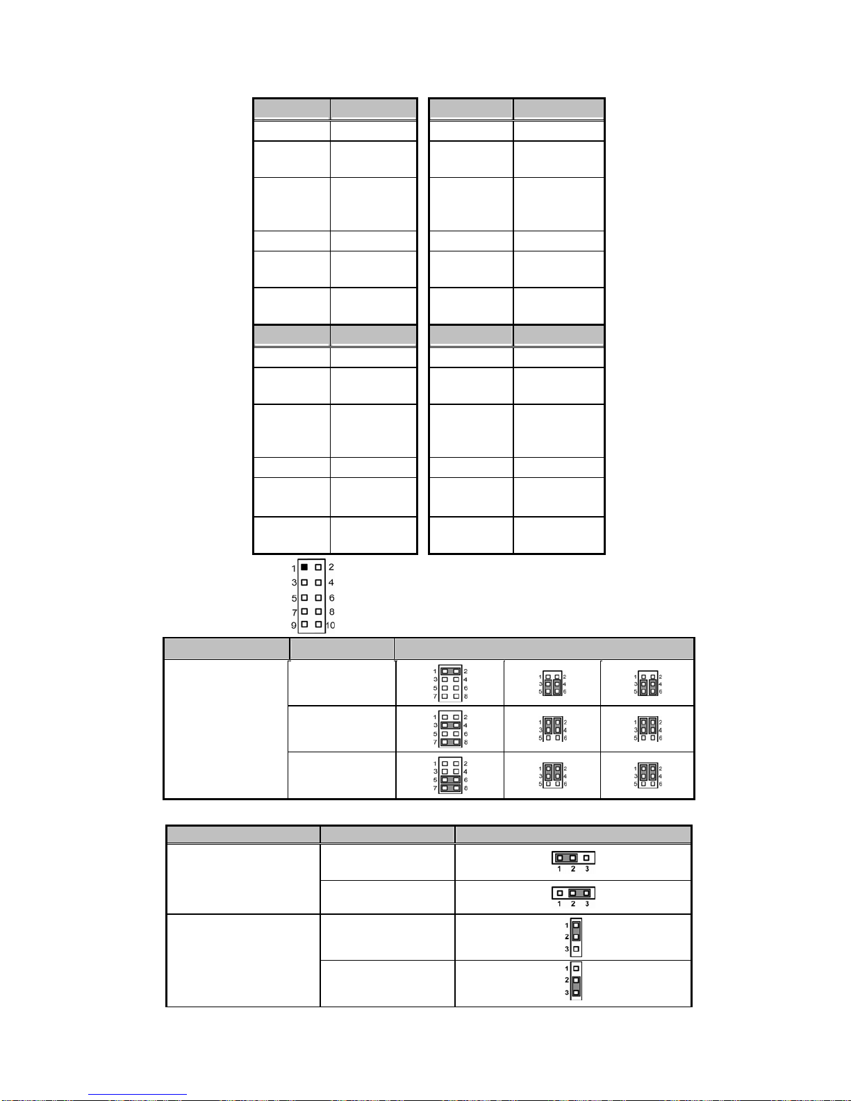
COM1~COM4 Mode Select for Type Jumpers: JP9, JP10, JP12, JP13
COM1 JP12 COM2 JP9
Pin 1=12V Short 1-3 Pin 1=12V Short 1-3
Pin 1=5V Short 3-5 or
5-7
Pin 1=5V Short 3-5 or
5-7
*Pin
1=DCD
(Default)
Short 7-9 *Pin
1=DCD
(Default)
Short 7-9
Pin 9=12V Short 2-4 Pin 8=12V Short 2-4
Pin 9=5V Short 4-6 or
6-8
Pin 8=5V Short 4-6 or
6-8
*Pin 9=RI
(Default)
Short 8-10 *Pin 8=RI
(Default)
Short 8-10
COM3 JP10 COM4 JP13
Pin 1=12V Short 1-3 Pin 11=12V Short 1-3
Pin 1=5V Short 3-5 or
5-7
Pin 11=5V Short 3-5 or
5-7
*Pin
1=DCD
(Default)
Short 7-9 *Pin
1=DCD
(Default)
Short 7-9
Pin 8=12V Short 2-4 Pin 8=12V Short 2-4
*Pin 8=5V
(Default)
Short 4-6 or
6-8
Pin 8=5V Short 4-6 or
6-8
Pin 8=RI Short 8-10 *Pin 8=RI
(Default)
Short 8-10
JP9, JP10, JP12, JP13
Description Function Jumper Setting
RS-232
(Default)
RS-422
COM1 Mode
Select (JP14/JP8/
JP11)
RS-485
Description Function Jumper Setting
3.3V (Default)
LVDS Voltage Select
(JP3)
5V
3.3V (Default)
CompactFlash Voltage
Selection (JP6)
5V
Page 56

PP-9260 series user’s manual ver 1.0
52
Normal (Default)
CMOS Clear (JP5)
Clear CMOS
Page 57
PP-9260 series user’s manual ver 1.0
53
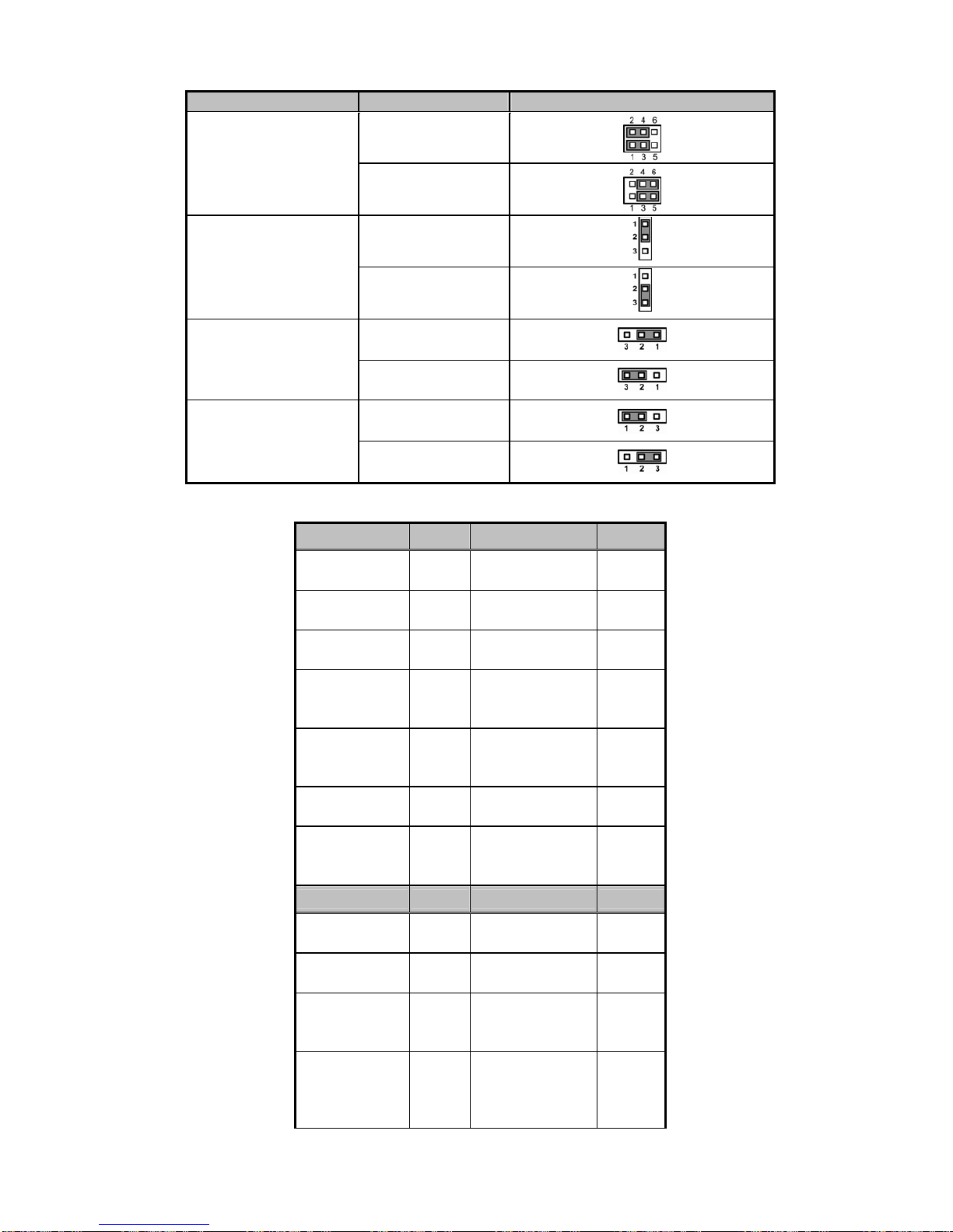
Description Function Jumper Setting
Line Out (Default)
Audio Line
Out/Speaker Out
Selection (JP15)
Speak Out
Slave (Default)
CompactFlash Mode
Selection (JP1)
Master
ATX (Default)
Power ATX/AT Mode
Selection (JP2)
AT
5V_SBY
USB Voltage Selection
(JP4/ JP7/ JP16)
5V (Default)
III. Connectors
Connector Label Connector Label
Power Control
Connector
CN1
Serial Port3
Connector
COM3
EPIC
EXPRESS Slot
CN2
Serial Port4
Connector
COM4
Power-Out
Connector
CN3
CompactFlash™
Socket
CFS1
LVDS
Backlight
Connector
CN4 DDRII SO-DIMM DIMMS1
LVDS1
Connector
CN5
Digital Visual
Interface (DVI)
Connector
DVI1
SM BUS
Connector
CN6
CPU FAN
Connector
FAN1
Front Panel
Bezel
Connector
CN8
System FAN
Connector
FAN2
Connector Label Connector Label
Audio
Connector
CN9
Parallel IDE
Connector
IDE1
Digital I/O
Connector
CN11 LAN2 Connector LAN2
LAN2
Connector
(Optional)
CN12
Parallel Port
Connector
LPT1
6-Pin Mini Dim
Keyboard /
Mouse
Connector
CN13
USB Port0 &
Port1 Connector
USB1
Page 58

PP-9260 series user’s manual ver 1.0
54
+12V-IN Power
Connector
ATX1
USB Port2 &
Port3 Connector
USB2
Serial Port1
Connector
COM1
USB Port4 &
Port5 Connector
USB3/
USB4
Serial Port2
Connector
COM2
SATA
Connectors
SATA1/2
Page 59
PP-9260 series user’s manual ver 1.0
55
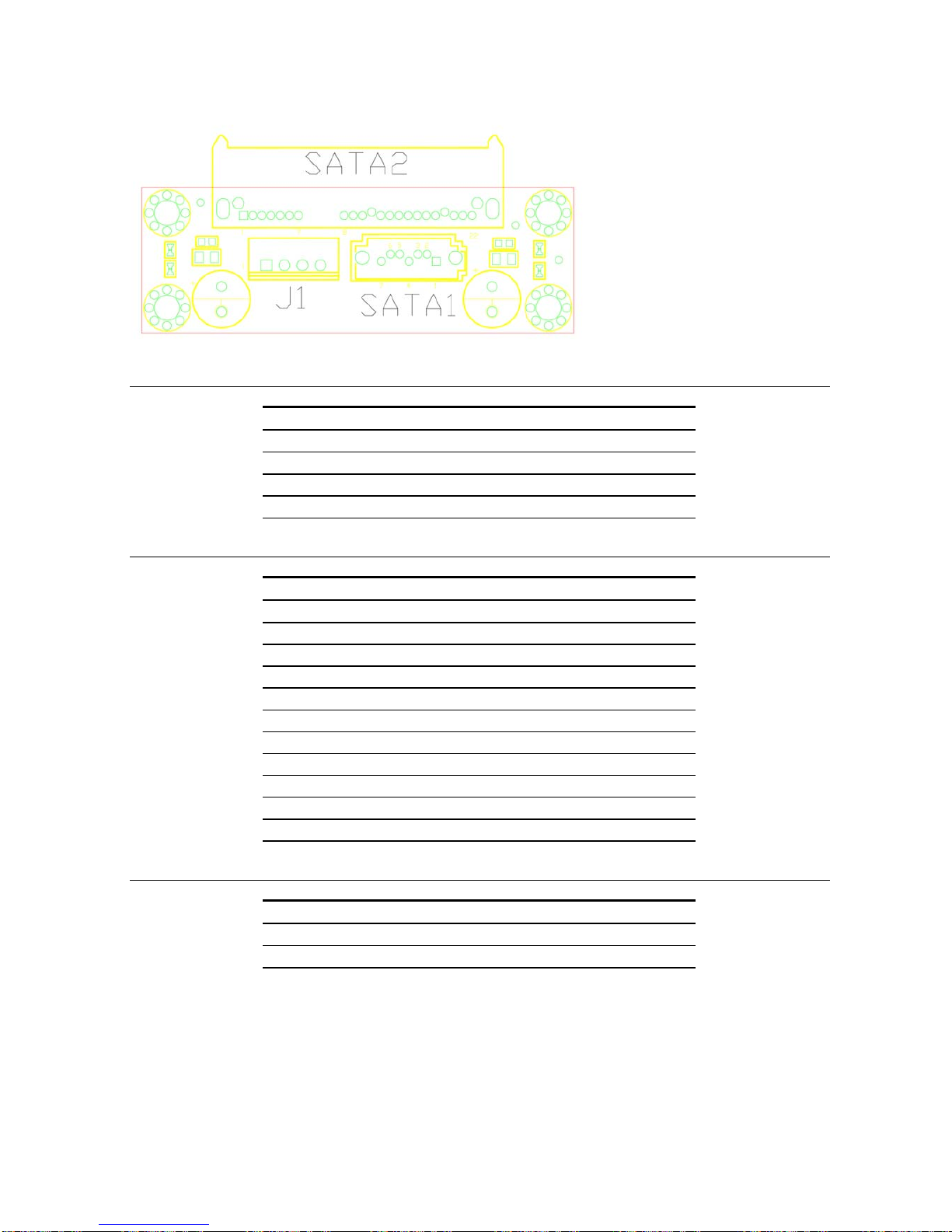
SATA docking board
SATA 7PIN Connector(SATA1)
Pin Signal Pin Signal
1 GND 2 STXP_1
3 STXN_1 4 GND
5 SRXN_1 6 SRXP_1
7 GND
SATA 22PIN Connector(SATA2)
Pin Signal Pin Signal
1 GND 2 STXP_1
3 STXN_1 4 GND
5 SRXN_1 6 SRXP_1
7 GND 8 N/A
9 N/A 10 N/A
11 GND 12 GND
13 GND 14 +5V
15 +5V 16 +5V
17 GND 18 N/A
19 GND 20 N/A
21 N/A 22 N/A
SATA Power Connector(J1)
Pin Signal Pin Signal
1 +12V 2 GND
3 GND 4 +5V
Page 60

PP-9260 series user’s manual ver 1.0
56
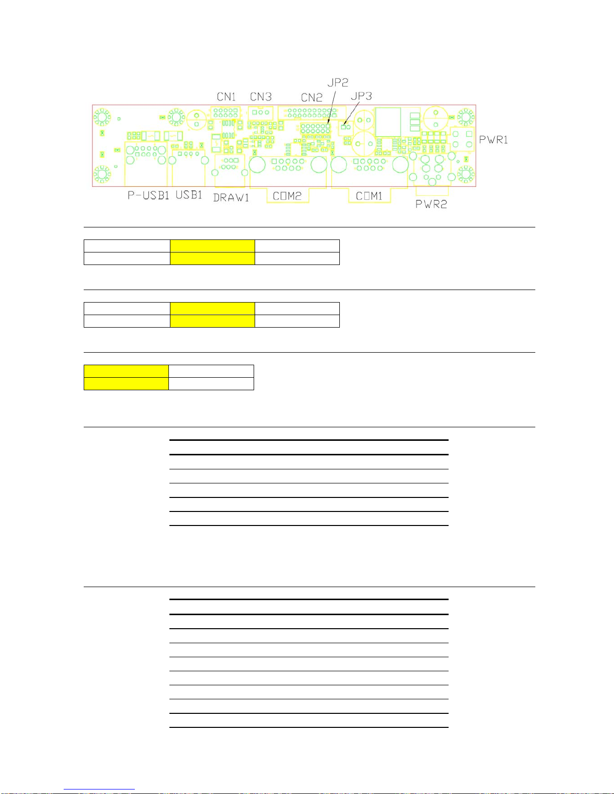
PP-9265 I/O board
COM4 Ring/+5V/+12V Selection(JP2)
1-2
3-4 5-6
+12V +Ring +5V
COM2 Ring/+5V/+12V Selection(JP2)
7-8
9-10 11-12
+12V +Ring +5V
DRAW +12V/GND Selection(CN3)
1-2 2-3
+12V GND
2Port USB Connector(CN1)
Pin Signal Pin Signal
1 GND 2 GND
3 GND 4 GND
5 USBD0+ 6 USBD1+
7 USBD0- 8 USBD19 +5V 10 +5V
Serial Port Connector(CN2)
Pin Signal Pin Signal
1 DCD4 2 DSR4
3 RXD4 4 RTS4
5 TXD4 6 CTS4
7 DTR4 8 RI4
9 DCD2 10 DSR2
Page 61

PP-9260 series user’s manual ver 1.0
57
11 RXD2 12 RTS2
13 TXD2 14 CTS2
15 DTR2 16 RI2
17 DIO OUT 0 18 DIO IN 0
19 DIO OUT 1 20 GND
Power Control Connector(JP3)
Pin Signal Pin Signal
1 PWR_PSON 2 GND
+12V Power Connector(PWR1)
Pin Signal Pin Signal
1 GND 2 GND
3 +12V 4 +12V
Power Input Connector(PWR2)
Pin Signal Pin Signal
1 +12V 2 GND
3 +12V 4 GND
USB Connector(USB1)
Pin Signal Pin Signal
1 +5V 2 +5V
3 USBD0+ 4 USBD1+
5 USBD0- 6 USBD17 GND 8 GND
Digital I/O Connector(DRAW1)
Pin Signal Pin Signal
1 GND 2 DI/O Out 0
3 DI/O IN 0 4 +12V
5 DI/O Out 1 6 GND
COM2 Serial Port Connector(COM2)
Pin Signal Pin Signal
1 DCD2 6 DSR2
2 RXD2 7 RTS2
3 TXD2 8 CTS2
4 DTR2 9 +5V/+12V/RI
5 GND 10 N/A
COM4 Serial Port Connector(COM1)
Page 62

PP-9260 series user’s manual ver 1.0
58
Pin Signal Pin Signal
1 DCD4 6 DSR4
2 RXD4 7 RTS4
3 TXD4 8 CTS4
4 DTR4 9 +5V/+12V/RI
5 GND 10 N/A
Page 63
PP-9260 series user’s manual ver 1.0
59
PP-9267 I/O board
COM4 Ring/+5V/+12V Selection(JP2)
1-2
3-4 5-6
+12V +Ring +5V
COM2 Ring/+5V/+12V Selection(JP2)
7-8
9-10 11-12
+12V +Ring +5V
DRAW +12V/GND Selection(CN3)
1-2 2-3
+12V GND
2Port USB Connector(CN1)
Pin Signal Pin Signal
1 GND 2 GND
3 GND 4 GND
5 USBD0+ 6 USBD1+
7 USBD0- 8 USBD19 +5V 10 +5V
Serial Port Connector(CN2)
Pin Signal Pin Signal
1 DCD4 2 DSR4
3 RXD4 4 RTS4
5 TXD4 6 CTS4
7 DTR4 8 RI4
9 DCD2 10 DSR2
11 RXD2 12 RTS2
13 TXD2 14 CTS2
15 DTR2 16 RI2
Page 64

PP-9260 series user’s manual ver 1.0
60
17 DIO OUT 0 18 DIO IN 0
19 DIO OUT 1 20 GND
Power Control Connector(JP3)
Pin Signal Pin Signal
1 PWR_PSON 2 GND
+12V Power Connector(PWR1)
Pin Signal Pin Signal
1 GND 2 GND
3 +12V 4 +12V
Power Input Connector(PWR2)
Pin Signal Pin Signal
1 +12V 2 GND
3 +12V 4 GND
Powered USB Connector(P-USB1)
Pin Signal Pin Signal
1 +5V 2 USBD03 USBD0+ 4 GND
5 GND 6 +12V
7 +12V 8 GND
USB Connector(USB1)
Pin Signal Pin Signal
1 +5V 2 USBD13 USBD1+ 4 GND
Digital I/O Connector(DRAW1)
Pin Signal Pin Signal
1 GND 2 DI/O Out 0
3 DI/O IN 0 4 +12V
5 DI/O Out 1 6 GND
COM2 Serial Port Connector(COM2)
Pin Signal Pin Signal
1 DCD2 6 DSR2
2 RXD2 7 RTS2
3 TXD2 8 CTS2
4 DTR2 9 +5V/+12V/RI
5 GND 10 N/A
Page 65
PP-9260 series user’s manual ver 1.0
61
COM4 Serial Port Connector(COM1)
Pin Signal Pin Signal
1 DCD4 6 DSR4
2 RXD4 7 RTS4
3 TXD4 8 CTS4
4 DTR4 9 +5V/+12V/RI
5 GND 10 N/A
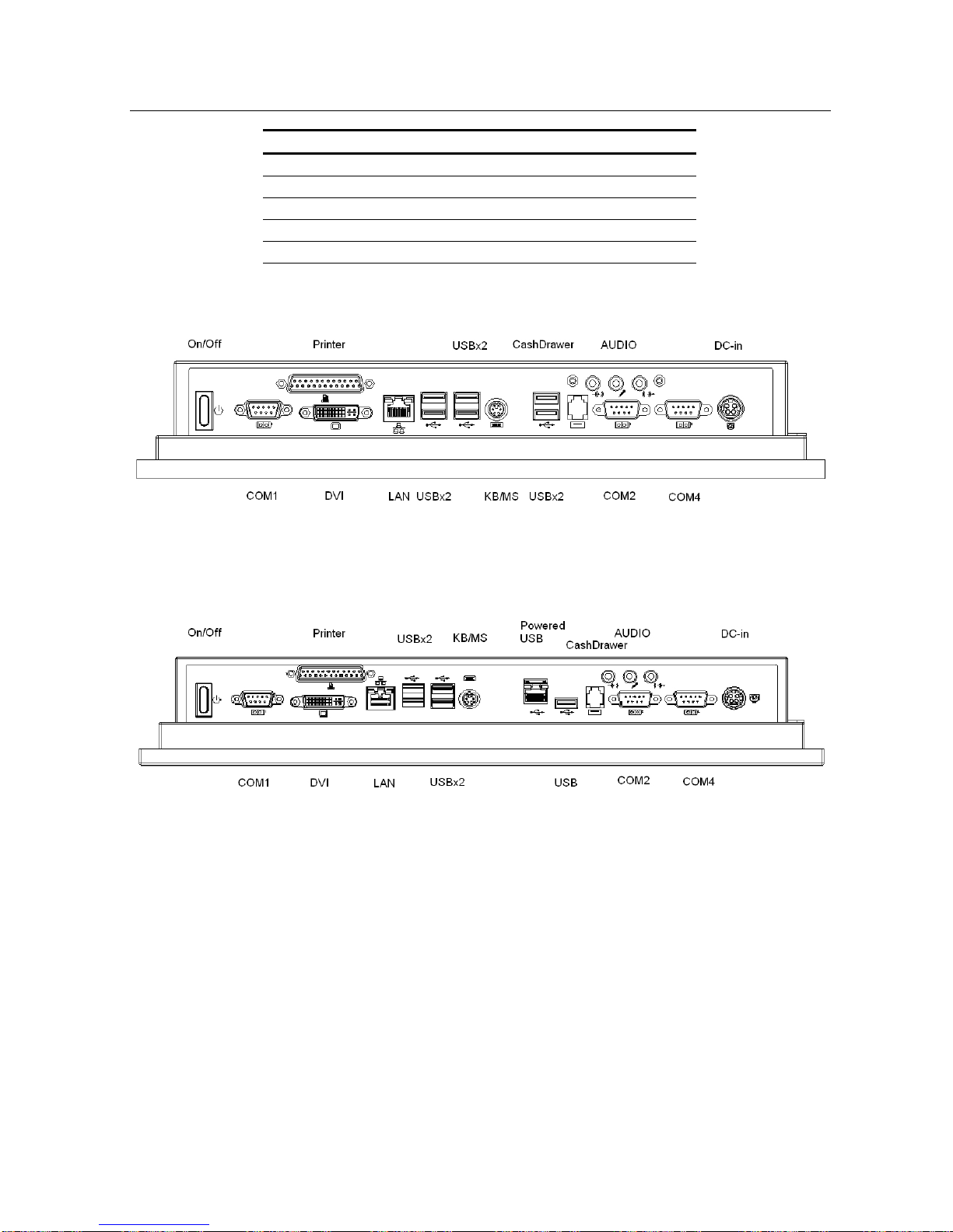
PP-9265 system I/O panel
PP-9267 system I/O panel
 Loading...