

Page 1

HFC3000E-HW-1
HHaannddhheelldd NNuuttrruunnnneerr
HHFFCC33000000 IInnssttrruuccttiioonn MMaannuuaall
October 2016 (Preliminary Release)
Page 2

Copyright (C) 2016 FEC AUTOMATION SYSTEMS. All Rights Reserved.
Page 3

Thank you for purchasing our Handheld Nutrunner.
This instruction manual describes the procedures for installation, and handling, and actions to
be taken in case of any failure.
◆ This instruction manual shall be delivered to the end user who operates the equipment.
◆ Read all instructions before use, and always keep this instruction manual with the equipment.
◆ Items not described in this instruction manual shall be considered “unavailable.”
◆ The product specification and appearance described in this instruction manual are subject to change without notice.
◆ All rights reserved. Any disclosure, copying, distribution, or use of the information contained herein is strictly
prohibited.
◆ It is important for you to read all “Safety Precautions” before using the equipment, and understand and observe
all instructions and recommendations included in this manual.
◆ Read all instructions and recommendations included in this manual, understand the functions and performance
of this nutrunner, and use this machine correctly.
◆ Wirings and parameter settings shall be conducted by a professional engineer.
◆ Indicate the following on all instruction manuals that use this equipment.
・This equipment is capable of high voltages hazardous to human life.
◆ Never conduct a withstand voltage test or megger test on this equipment.
For the safety of operator and equipment
Please confirm the following when unpacking this equipment.
◆ Confirm that you received the correct model that you had ordered.
◆ Confirm that there are no missing parts, accessories or tools. (Refer to the system structure
specification list.)
◆ Check for any damage caused during transportation.
Points to check when unpacking
Introduction
Page 4

Warranty Period
The warranty period of this equipment is 1 year from the date of purchase or the date
of delivery to the designated place.
Scope of Warranty
If a malfunction occurs in the equipment in the state of correct use in accordance with
this instruction manual within the warranty period, repair or replacement shall be
performed free of charge. However, accommodations shall be charged accordingly
in the following cases, even within the warranty period.
1. If the cause of a malfunction is a condition, environment, handling, etc., falling
outside that which is indicated in the instruction manual.
2. If a malfunction is due to a modification or repair performed by the customer.
3. If the cause of a malfunction is an apparatus other than this equipment.
4. If a malfunction is due to use outside the specification ranges of this equipment.
5. If the cause of a malfunction is an act of God or other disaster.
The scope of this warranty is limited to the main body of our equipment and damage
induced by a malfunction of this equipment shall be excluded from the warranty.
Warranty
Introduction
Page 5

Read all instructions before operating the equipment in order to use this equipment safely and correctly.
Prior to use, read this instruction manual carefully and fully understand the equipment functions, safety
precautions and instructions.
Safety precautions in this manual are ranked as [Warning] or [Caution].
To prevent danger to the user and other persons as well as property damage, the instructions that must
be fully observed are marked with the symbols below.
◆ This instruction manual uses the following two symbols according to the degree of damage that may
be caused when the instruction is not observed.
Even instructions that are marked with may result in severe damage if they are not observed
according to conditions. Contents marked with the above symbols are very important instructions. For
your safety, follow all instructions marked with the symbols.
◆ This instruction manual uses various symbols for instructions that shall be observed.
Warning
This symbol indicates that failure to observe instruction marked with
this symbol may result in severe personal injury or death.
This symbol indicates that failure to observe instruction marked with
this symbol may result in minor personal injury or material damage.
Warning:
Fire
Ground
Prohibited
Do not
disassemble
Required
Warning:
Electrical shock
Safety Precautions
Caution
Caution
Caution: Fire
Caution:
Electrical shock
Caution: High
Temperature
Page 6

Do not remove the motors and gear cases of tools.
The tool output spindle may rotate and cause injury.
Do not repair, disassemble, or modify the equipment.
Failure to observe this instruction may cause injury, electric shock, fire, or malfunction.
Never operate the equipment where it is exposed to water or near corrosive atmosphere and
flammable gases. Failure to observe this instruction may cause fire.
Do not touch the connectors while the equipment is turned ON and for a while after the
equipment is turned OFF. Failure to observe this instruction may cause an electric shock.
Wiring operation and maintenance work shall be conducted by a professional engineer.
Failure to observe this instruction may cause an electric shock or injury.
Turn OFF the power when conducting wiring operation and maintenance and inspection.
Failure to observe this instruction may cause electric shock and injury.
Never damage the cables, apply excessive strength to cables, or squeeze the cables.
Never use damaged power cables.
Failure to observe this instruction may cause an electric shock or fire.
It takes 15 minutes for capacitor discharging. Do not touch the unit and terminals immediatey
after power off.
Be sure to conduct type-3 grounding for the FG terminals.
Failure to observe this instruction may cause electric shock.
In case of abnormal odor, noise, or operation error occurs, stop operation immediately
and turn OFF the power source.
Failure to observe this instruction may cause injury or fire.
Safety Precautions
Warning
Page 7

Transport the equipment properly according to its weight.
Failure to observe this instruction may cause injury and malfunction.
The conditions when transporting the equipment by ship are as below.
◆ Ambient temperature: -5°C ~ +55°C (Avoid freezing)
◆ Ambient humidity: 50% RH or lower (Avoid moisture)
◆ Package: Tight seal
Do not hold cables and output spindles when transporting the tools.
Failure to observe this instruction may cause injury or malfunction.
The equipment shall be stored under the following conditions.
◆ Ambient temperature: -5°C ~ +55°C (Avoid freezing)
◆ Ambient humidity: 90% RH or lower (Avoid moisture)
◆ Atmosphere: Indoors (Avoid direct sunlight)
No corrosive gases or flammable gases
No oil mist, dust, water, salt, iron powder
◆ Avoid direct vibration or shocks.
Failure to meet the above conditions may cause earth leakage and malfunction.
Caution
Transportation/Storage
Safety Precautions
Page 8

Installation/Wiring
Install the controller using the specified screws.
Failure to observe this instruction may cause malfunction.
Use the specified combination of the tool and the controller.
Failure to observe this instruction may cause fire and malfunction.
The power input parts must be provided with safety measures such as breakers and
circuit protectors.
Failure to observe this instruction may cause fire and malfunction.
Do not use a tool or a controller that has damages or missing parts.
Failure to observe this instruction may cause fire, injury, and malfunction.
Do not get on the top of equipment or place a heavy object on the top of equipment.
Failure to observe this instruction may cause injury, and malfunction.
Do not subject the equipment to excessive shock or impact.
Failure to observe this instruction may cause malfunction.
Provide proper and firm wiring.
Failure to observe this instruction may cause injury, fault, and malfunction.
Operate the equipment with the specified power supply voltage.
Failure to observe this instruction may cause injury, electric shock, fire, and malfunction.
When operating the equipment at a location such as the following, take sufficient measures to
shield the equipment.
◆Location where noise is generated
◆Location where the equipment is subjected to a strong electric field or magnetic field
◆Location a power wire is not laid nearby.
Failure to observe this instruction may cause injury, fault, and malfunction.
Caution
Safety Precautions
Page 9

Operation/Adjustment
Never operate the equipment with wet hands.
Failure to observe this instruction may cause electric shock.
Use the equipment under the following conditions.
◆Ambient temperature: 0°C~+45°C (Avoid freezing)
◆Ambient humidity: 90% RH or lower (Avoid moisture)
◆Atmosphere: Indoors (Avoid direct sunlight)
No corrosive gases or flammable gases
No oil mist, dust, water, salt, iron powder
◆Avoid direct vibration or shocks.
Failure to meet these conditions may cause earth leakage and malfunction.
Confirm and adjust all parameters before operation in order to prevent unexpected movement
of the equipment.
Failure to observe this instruction may cause an injury, malfunction, or fault.
Never conduct extreme adjustments or setting change that may cause instability of operation.
Failure to observe this instruction may cause an injury, malfunction, or fault.
Do not turn ON and OFF the equipment repeatedly. Failure to observe this instruction may
cause a malfunction.
Do not use the equipment at a torque higher than the maximum torque.
Failure to observe this instruction may shorten equipment life or cause breakage due to high
temperature caused by overload.
In case any abnormality occurs, remove the cause and ensure safety before resetting and
restarting the equipment.
Failure to observe this instruction may cause injury.
It is occurred reaction in sudden rise torque in the following cases.
Please attach the reaction jig.
Retightening bolt(nut) which already tighten.
Loosing bolt(nut) which already tighten.
Caution
Safety Precautions
Page 10

Table of Contents
Chapter 1 Outline
1-1 How to Use This Instruction Manual 1-2
1-2 Features 1-3
1-3 Usage Precautions 1-5
Chapter 2 Specifications
2-1 System Specifications 2-2
2-1-1 Duty Cycle Calculation 2-2
2-1-2 Unit Specifications 2-2
2-2 Performance 2-3
2-2-1 Fastening Performance 2-3
2-2-2 Unit 2-3
2-3 Functions 2-4
2-3-1 Main Functions 2-4
2-3-2 Fastening Methods 2-5
Chapter 3 Part Names
3-1 Unit 3-2
3-1-1 Unit Front Panel 3-2
3-1-2 Unit Rear Panel 3-3
3-2 Tools 3-4
3-2-1 Angle Tool 3-4
3-2-2 Pistol Tool 3-5
Chapter 4 Installation
4-1 Installation Procedure 4-2
4-2 Unit Outer Shape and Installation Dimensions 4-3
4-3 Input Power Source Connection 4-4
4-4 Tool Cable Specifications 4-5
4-5 External Control Signal Connection 4-6
4-5-1 Unit I/O Signals [BANK SELECT=OFF] 4-7
4-5-2 Unit I/O Signals [BANK SELECT=ON] 4-8
4-5-3
Input and Output Circuit Specifications and Recommended Connection Circuit
4-9
4-5-4 Description of I/O Signals 4-10
4-5-5 Timing Chart 4-16
4-6 External Monitoring Device Signal 4-18
4-7 RS-232C Interface Signal 4-19
4-7-1 RS232C Specification (RS232C-1) 4-20
4-7-2 Data Format (RS232C-1) 4-21
4-8 Ethernet Interface 4-23
Page 11

Table of Contents
Chapter 5: Power Activation and Operational Tests
5-1 Items to be Checked Before Power Activation 5-2
5-2 Items to be Checked When Activating the Equipment 5-3
5-3 Input Initial Setting Data 5-4
5-4 Items to be Checked After Activation 5-4
Chapter 6 Description of Operations
6-1 Changing between RUN and PROGRAM Modes 6-2
6-2 RUN Mode 6-5
6-2-1 Changing Modes in the RUN Mode 6-6
6-2-2 Indications in the RUN Mode (Real Time Mode) 6-7
6-2-3 Indications in the RUN Mode (Fastening Result Mode) 6-10
6-2-4 Indications in the RUN Mode (Parameter Setting Mode) 6-12
6-2-5 Indications in the RUN Mode (System Setting Mode) 6-13
6-2-6 Indications in the RUN Mode (Operation View) 6-14
6-3 PROGRAM Mode 6-16
6-3-1 Changing Modes in the PROGRAM Mode 6-16
6-3-2 Indications in the PROGRAM Mode (Set Value Selection Mode) 6-17
6-3-3 Indications in the PROGRAM Mode (Set Value Editing Mode) 6-19
6-4
Copying of Parameters/Erasure of the Fastening Result Record/Formatting of the CF Card
6-21
6-5 Fastening NG (Failure) Result Indications 6-23
6-5-1 Example of Fastening NG item indication 6-24
6-5-2 NG Judgment 6-26
6-6 Parameter Structure 6-36
Chapter 7 Troubleshooting
7-1 Abnormal State Display 7-2
7-2 Abnormality Details/Causes and Recovery Methods 7-3
7-3 Axis Judgment: Checking the Contents of the REJECT 7-9
7-4 Ethernet Communication 7-10
7-5 RTC 7-12
Chapter 8 Options
8-1 CompactFlash (CF) Card 8-2
8-2 Expansion RS232C Interface 8-7
Chapter 9: External Interface
9-1 Common specifications 9-2
9-2 EtherNet/IP 9-7
9-3 CC-Link 9-12
9-4 PROFIBUS DP-V1 9-19
9-5 DeviceNet 9-24
9-6 PROFINET IO 9-29
Page 12

Table of Contents
Chapter 10 Warranty and Servicing
10-1 Warranty 10-2
10-1-1 Warranty Period 10-2
10-1-2 Scope of Warranty 10-2
10-2 Servicing System 10-3
Appendix: List of Tool Models
Page 13

Revision History
Revision
date
Jan, 2016 HFC3000E-HW-1 1st Edition
DSP1500 = Servo Press
AFC3000 = Nutrunner
FUSION = DC Hand
HFC3000 = DC Hand
E = English Version
S = Spanish Version
*Japanese Version furnished by DDK
uses DDK numbering convention.
Manual No.
Manual Numbering Convention
HFC3000E-HW-1
Tool
Tool
Content of revision
(SupportingV1.000) – Release from DDK (S0140185-C)
Version Number
(Major Revision Level)
HW = Hardware Operation Manual
SW = Software Manual
Page
Page 14

Notes
Page 15

Chapter 1 Outline
PAGE 1-1
Chapter 1 Outline
1
Page 16

Chapter 1 Outline
PAGE 1-2
1-1 How to Use This Instruction Manual
This manual describes the system structure, specifications, handling method, etc., of the Handheld
Nutrunner System.
These are described in the following order in this manual:
Chapter
Items
Contents
Chapter 1
Outline
Description of functions and precautions.
Chapter 2
Specifications
General specifications of the Hand System.
Chapter 3
Names of Parts
Names and functions of the respective parts of the controller
and the tools.
Chapter 4
Installation
Installation procedure
Chapter 5
Power Activation and
Operational Tests
Items to be checked before power activation and procedures
for operational tests.
Chapter 6
Description of
Operations
Descriptions of items displayed on the panel and instructions
for setting the fastening set values.
Chapter 7
Troubleshooting
Descriptions of abnormal operation indications during
operation and corrective actions.
Chapter 8
Options
Optional functions
Chapter 9
Fieldbus
Fieldbus setting and functions
Chapter 10
Warranty and Servicing
Warranty period and servicing system
Page 17

Chapter 1 Outline
PAGE 1-3
1-2 Features
The Handheld Nutrunner is a flexible fastening tool equipped with a compact, high-performance
servomotor developed especially for this product. Like the usual high-performance nutrunner system, it
is designed to accommodate various tool models and provide useful functions for error proofing, data
management, data communication, etc.
☆ Compact Design
The controller operates on single-phase 100V ~ 240V, making installation work related to the
primary power source easy.
☆ Fastening Functions
Fastening can be performed by the torque method or the angle method. An angle monitor and a
torque rate monitoring function are provided as functions for error proofing. A fastening counting
function can be used as an additional error proofing method.
☆ 64 Programmable Parameter Sets
64 selectable parameter sets are available for ‘on-the-fly’ model/torque setting changes
Work (parameter) selection can be performed by external signals.
Controller memory is non-volitile - a backup battery is not required, thus no need to worry about
problems such as dead batteries, battery maintenance, etc.
☆ Data Communication
An RS-232C interface is incorporated to enable data communication with external devices.
A dedicated Ethernet connector that enables communication with a PC (for dedicated software) is
provided. Connectors enabling sending of result data to a PLC or other external device are also
provided.
Optional fieldbus interfaces that allow fastening data to be sent of over the same fieldbus connection
to the PLC, can be installed. (ie. Ethernet I/P, Devicenet, Profinet, CCLINK, etc.)
☆ Motor
A permanent magnet High Speed DC motor provides for improved fastening control. The sealed
design of the motor provides greater protection from contamination without generating excess heat.
The resolver is uniquely designed to withstand harsh environments and provide high-resolution
control / angular feedback signals.
☆ Preamplifier
Quality control of the tool torque transducer is accomplished electronically (digitally) through the
EEPROM (Electrically Erasable Programmable Read Only Memory) in the preamplifier. During
factory setup of the torque transducer, the unit is Dead Weight and Dynamically tested against
Standards that are certified and traceable to the National Institute of Standards and Technology.
The resultant data is then programmed into the preamplifier where it is stored on non-volatile
EEPROM. The preamplifier also contains the “Smart Tool ID” system that allows automatic tool
recognition and protects against misapplication of tools onto the wrong controller or set-up.
☆ Self-Check Function
Each time a fastening operation starts, a calibration check of the torque transducer is performed to
check functionality including those of the controller and the cables to prevent abnormal fastening.
☆ Abnormal Condition Display
When an abnormality occurs, the corresponding abnormal state No. is displayed on the front panel.
Page 18

Chapter 1 Outline
PAGE 1-4
☆ Fastening Result Record
Fastening resultant data is saved in a nonvolatile controller memory (approx. 12,000 cycles of data).
100 sets of torque curve data is stored in volatile memory (RAM).
100 sets of Reject curve data is stored in nonvolatile memory.
The fastening resultant data and the Reject curve data are therefore preserved even if the power is
turned off. However, the normal torque curve data is lost when the power is turned off. The above
data can be read with the User Console software.
●Fastening Result Storage Feature List of HFC3000 System
Function Name
Automatic Save *1
Stored Data
HFC3000
User Console
Fastening
Data
Curve Data
Fastening Data
Setting Tab
Preferences
Auto Upload
Stored Data
Storage Content
Stored Data
Curve Data
Stored Data
Abnormals
Storage Location
PC
Each controller
Storable Records
-
12000
results
500 results
Setting Item
Yes
No
JUDGMENT
ACCEPT
○ ○ ○
REJECT
○ ○ ○
ABNORMAL
○ ○ ○
○
BYPASS
○ ○ ○
STOP
○ ○ ○
RESET
STOP
○ ○ ○
START OFF
○ ○ ○
*1:’Automatic Save’ must be enabled during data collection in the Fastening Data screen of
the AFC3000 User Console
Function Name
Stored Curve Data
CF Card *2
HFC3000
User Console
Stored Curve Data
-
Storage Content
Stored Curve
Data *3
Stored Reject
Curve Data
Stored
Data
Curve Data
Storage Location
Each controller
CF Card
Storable Records
100 results
-
-
Storage Format
Torque-Angle (540deg)
-
Torque-Angle (180deg)
JUDGMENT
ACCEPT
○
○ ○
REJECT
○
○ ○ ○
ABNORMAL
○
○ ○ ○
BYPASS
○
○ ○
STOP
○
○ ○ ○
RESET
STOP
○
○ ○
START OFF
○
○ ○ ○
*2:CF CARD Option and CF CARD are required separately.
*3:The stored (curve data) will be cleared when the control power of the controller is turned OFF.
Page 19

Chapter 1 Outline
PAGE 1-5
1-3 Usage Precautions
To insure use in the best conditions, please conform to the following instructions.
☆ Handling of tool
Tools can generate a large amount of torque during operation, and the reaction force is applied to the
Operator or mounting area of the tool. Therefore, tools must be installed in the proper positions and
with adequate reaction devices. Tools MUST be mounted either using their supplied mounting plate
or clamped only in designated areas of the tool or tool damage may result.
Keep in mind that the fastening tool is a strain gage based instrument and, although it has been
designed to withstand sudden shock, repeated shock (over time) could damage some components.
Therefore, support devices must be used whenever practical to ease in handling and operation of the
Fastening Tool.
☆ Fastening
Avoid fastening beyond the full scale torque. Do not use a duty cycle (the ratio of the tool “On” time
to Tool “Off” time) higher than 50%, even when the torque is below the full scale value.
☆ Cable Connection
Use the specified/supplied cables for all system connections.
Completely lock the tool cable twist lock connectors.
PLC I/O cables must be run separate from any high voltage power sources or cabling, and must
not exceed 50 feet in length.
GROUNDING of the controller is REQUIRED (Perform Class 3 grounding) – Make sure the
controllers power cable ground pin is connected to a proper ground or DANGER OF ELECTRICAL
SHOCK EXISTS. Supply primary power with a cable no SMALLER than 1.25mm2 (17AWG).
☆ Installation Environment
Controller units must be located a minimum of 600 mm from high transient voltage sources such as
transformers, motor starters, AC inverters and AC contactors. If it cannot be avoided, the units must be
properly shielded.
DO NOT use at the following locations.
Areas under direct sunlight.
Areas where the environmental temperature is out of the 32 °~122°F (0° ~ 45°C) range.
Areas where the relative humidity is below the 20% range.
Areas where the relative humidity is above the 90% range.
Areas where the temperature changes quickly, which may cause condensation.
Areas where conductive powder, oil mist, saline, or organic solvents exist.
Areas that have corrosive or combustible gases.
Areas that have strong electric or magnetic fields.
Areas where a strong vibration or shock could be transmitted directly to a Controller unit or tool.
☆ Static Electricity
Since the controller is composed of many electronic components, please be aware of static
electricity. Excessive static electricity may occur at dry locations, therefore we recommend the
operator to touch grounded metal before operating the front panel operation switches to discharge
the static electricity charged inside the human body.
Page 20

Chapter 1 Outline
PAGE 1-6
☆ Cleaning
Do not use any organic solvents, such as thinner, to clean a Controller or a tool. The solvent could
melt the surface paint, or penetrate inside and cause damage. A cloth dampened with alcohol or
warm water should be used to lightly wipe the components.
☆ Noise
The controller is made up of electronic components – therefore, make sure there is no equipment
that will generate strong electrical noise in the surroundings.
Make sure that the cables that connect the controller and the tool are not placed inside a duct, etc.,
together with a power source line or other wiring.
☆ Handling and Shipping
It is critical that FUSION System components are properly handled and shipped in order to maintain the
System's integrity. Adhere to the following requirements for shipping and handling:
Loose FUSION System components must be individually packaged in an approved anti-static
container or wrap to prevent damage from electrostatic discharge.
Adhere to Chapter 2 Specifications for environmental requirements.
Page 21

Chapter 2 Specifications
PAGE 2-1
Chapter 2 Specifications
2
Page 22

Chapter 2 Specifications
PAGE 2-2
2-1 System Specifications
Power
Source
Voltage
Single-phase 100V AC~240V AC ±10%
(5m cable for 100-120VAC provided as accessory)
Frequency
50/60Hz
Installation environment
No vibration must be applied directly to the controller.
Forced-cooling equipment or heating equipment is required when
using the Controller outside the following operating range.
Operating
Conditions
Ambient
temperature
0°C~+45°C (Avoid freezing)
Ambient
humidity
No more than 90%RH (Avoid condensation)
Operation
range
Duty cycle: within 50% (within the prescribed time for one cycle)
See “2-1-1 Duty Cycle Calculation.”
Storage
Conditions
Ambient
temperature
-5°C~+55°C (Avoid freezing)
Ambient
humidity
No more than 90%RH (Avoid condensation)
Shipping
Conditions
Ambient
temperature
-5°C~+55°C (Avoid freezing)
Ambient
humidity
No more than 50%RH (Avoid condensation)
Packing
method
Tight seal
Ambience
Indoors (no direct sunlight), free from corrosive gas, flammable
gas, oil mist, dust, and dirt.
2-1-1 Duty Cycle Calculation
The duty cycle for HFC series is calculated as follows.
Duty Cycle (%) = Rotating time ÷ (Rotating time + Downtime) × 100
2-1-2 Controller Specifications
Controller model
HFC-B016
Motor model
M50,M80
Power source voltage
Single phase 100~240V AC ±10%
Power source frequency
Both 50/60HZ
Power consumption rating
80W
Maximum momentary current
11.3Ap (at the time of motor max power)
Inrush current
38Ap/AC100V,76Ap/AC200V
Power supply capacity
1.2kVA
Ground fault interrupter
(Sensitivity electric current)
⊿I 30mA Max
Page 23

Chapter 2 Specifications
PAGE 2-3
2-2 Performance
2-2-1 Fastening Performance
Torque precision
From 1/2 ~ Calibration torque
3σ/:
X
5% or less
From 1/4 ~ 1/2 Calibration torque
3σ/
X
: 6% or less
(Precisions in case of in-house standard fastening.
*May differ according to work.)
Angle display minimm unit
0.1 degree
Angle internal control unit
0.1 degree
Torque transducer accuracy
±1% of full scale
Torque transducer linearity
±0.5% of full scale
Fastening method
Torque method/Angle method
Torque rate setting
3
List of Tools Refer to Appendix.
MODEL
MAXIMUM
TORQUE
[Nm]
MAXIMUM
ROTATION
SPEED
[rpm]
MINIMUM
ROTATION
SPEED
[rpm]
HFT-015M50-A1
15.00
1215
1
HFT-025M80-A1
25.00
1070
1
HFT-060M80-A
60.0
446
1
HFT-080M80-A
80.0
330
1
HFT-130M80-A
130.0
203
1
HFT-015M80-S1
15.00
1600
1
HFT-040M80-A1
40.00
648
1
HFT-040M80-S
40.00
694
1
HFT-015M50-P1
15.00
1190
1
HFT-035M80-P1
35.00
778
1
2-2-2 controller
CPU: 32-bit RISC
Data communication: Ethernet: 1 port RS232C: 1 port
Fieldbus D-NET, P-BUS, CC-Link, etc. (optional)
Monitor functions: Torque, angle pulse, current
Page 24

Chapter 2 Specifications
PAGE 2-4
controller MODEL
HFC-B016-*-*-*-*
N:Option4 nothing EN:EtherNet
N:Option3 nothing CF:CF Card(RS232C-2)
N:Option2 nothing IO:I/O terminal is attached
N:Option1 nothing CC:CC-Link DN:DeviceNet
PB:ProfiBusDPV1 PI:ProfiNetIO EI:EtherNetI/P
2-3 Functions
2-3-1 Main Functions
(1) Fastening Function
The HAND SYSTEM is capable of the following fastening methods.
1. Torque method: Angle monitor, Torque rate monitor, 1/2/3 step fastening
2. Angle method: Torque monitor, Torque rate monitor, 1/2/3 step fastening
(2) Self-Check Function
When the start lever is gripped (turned ON), the home-position voltage level and CAL voltage level of
the torque transducer are automatically checked before fastening. This function is useful for
checking the transducer for abnormality and checking the cable for breakage etc.
(3) Bypass Function
When the BYPASS signal is input, the BYPASS signal is output to notify that the controller is in the
BYPASS mode. Starting by the START signal cannot be performed in this mode.
If the controller enters the BYPASS mode during fastening, fastening is stopped immediately.
(4) Abnormal Signal Output Function
When a fastening failure (NG) or a system error occurs, the tool is stopped immediately and a signal
corresponding to the problem is output. Also, the fastening failure (NG) details and the abnormal
state No. are displayed on the controller front panel.
(5) Tool Type Checking Function
If, when the Nutrunner is activated, the tool model set at the controller differs from the model No. of
the tool that is actually connected, the Tool Type Error is generated in the power activation process
and fastening will not be performed.
The tool ID contents are read in either of the following states.
1. If a tool is connected when the power is activated
2. When the tool is connected
Page 25

Chapter 2 Specifications
PAGE 2-5
2-3-2 Fastening Method
(1) Torque Method (Angle Monitor)
Fastening is performed up to a preset standard torque.
The fastening operation is performed with the preset torque as the target, and high limit/low limit
judgment of the angle value is enabled.
The number of fastenings steps is selectable among 1 step, 2 steps, and 3 steps.
(2) Angle Method (Torque Monitor)
Fastening is performed up to a preset standard angle.
The fastening operation is performed with the preset angle as the target, and high limit/low limit
judgment of the torque value is enabled.
Generally when a handheld tool is used, the angular precision may vary according to the state in
which the tool is held during fastening. Use in combination with the reaction force receiver jig etc.,
is recommended.
The number of fastenings steps is selectable among 1 step, 2 steps, and 3 steps.
(3) Differential Angle Check Method
Torque
Standard Angle
Rate 2 End Torque
Rate 2 Start Torque
1st Torque
Snug Torque
Differential Angle (fastening result) Angle
Differential Low Limit (-) Angle Differential High Limit (+) Angle
Seating point calculated from the value of rate 2
Fastening is performed from the Snug torque (angle measurement start torque) to the standard
angle value (or the standard torque value).
After completion of fastening, the seating point is calculated from the value of rate 2.
The differential angle is then calculated from the final torque value and the value of rate 2, and
judgment is performed if differential angle check is available.
The rate 2 is calculated from the rate 2 start torque and the rate 2 end torque.
Page 26

Chapter 2 Specifications
PAGE 2-6
Page 27

Chapter 3 Part Names
PAGE 3-1
Chapter 3 Part Names
3
Page 28

Chapter 3 Part Names
PAGE 3-2
3-1 Controller controller
3-1-1 Controller controller Front Panel
POWER
Controller main power
switch
CAL
Manual calibration check
pushbutton
RST
Reset pushbutton
PRG
Program mode select
pushbutton
SET
Switch for finalizing a
change of data
◁▷▵▿
Selection switches for
WORK, parameter, and
data setting.
NG (REJECT)
Lights up when even
one of the preset
judgment criteria is not
met by the fastening
results.
ANGLE
Lit up in the fastening angle
result display mode.
TORQUE
Lit up in the fastening torque
result display mode.
6-dight 7-segment LED
Displays a set value,
fastening result, or other
data.
3-dight 7-segment LED
Displays the WORK No.
(parameter).
3-digit 7-segment LED
COUNT/D-No.
Displays the cycle count
and the data No.
TOTAL OK
Lights up when
acceptable (OK)
fastening results are
obtained for the
designated number of
times, and turns off
when the batch reset
input signal is ON.
OK (ACCEPT)
Lights up when the
fastening results are
within the standard
value ranges of all
preset judgment criteria,
and flashes while
TOTAL OK is ON.
Page 29

Chapter 3 Part Names
PAGE 3-3
3-1-2 controller Rear Panel
Note : * FIELDBUS, CF card, RS232C-2 and Data report ethernet are optional.
Please do not change it AXIS ADDRESS(01)、SW1(1,2,7,8 ON)、SW2(ALL OFF).
T/A MON.
Connector for torque and angle
monitor output connection.
(PAGE 4-18)
RS232C-1
Connector for output of fastening
result data.
Can be connected to a PLC, printer,
PC, etc. (PAGE 4-19).
100~240V AC
Primary power source input
connector
Operates on a single-phase
50/60Hz power source.
Provide secure grounding.
TB1,2,3
Connector for input/output
connection.
Refer to separate section for signal
details and precautions (PAGE 4-6).
Electric leakage breaker
When an electric leakage
occurs in the Unit, cable, or
tool, this breaker trip
instantaneously to secure
safety from the electric
leakage.
I…ON
O…OFF
TOOL
Connector for tool cable
connection.
Twist lock type connector.
Can be connected and
disconnected by twisting by 90
degrees.
Various FIELDBUS ports
The communication specification
can be selected from among
DeviceNet, PROFIBUS, CC-Link,
etc., in accordance with the user
specifications (PAGE 9-1~).
*RS232C-2
For ID data input
*Under development
*CF Card
Stores fastening result data and
curve data.
*DATA REPORT ETHERNET
ETHERNET
For PC
Page 30

Chapter 3 Part Names
PAGE 3-4
3-2 Tools
3-2-1 Angle Tool
Hand-held type fastening tool provided with angle head, planetary gear, torque transducer,
servomotor, indicator LEDs, and operating switches.
①Starting switch: When the switch is turned ON (by pressing), the tool tip rotates for performing
fastening. When the switch is released during fastening (during rotation of the
tip), the fastening (rotation) is stopped. For ordinary fastening operation,
continue to grip this switch until fastening is completed.
②Reversing switch: Switch for switching between normal and reverse rotation operations.
This is a ring type normal/reverse changeover switch (*in older models, this is a
push type switch). When the reverse rotation mode is set, the judgment LED
flashes in orange.
When the starting switch is turned ON in this state, the reverse rotation operation
is performed. When the starting switch is released during the reverse rotation
operation, the operation is stopped.
* The torque limit is caused when you loose the bolt already fastened over 5N・m of
default setting in the case of the reverse operation and it automatically stops for safety.
This can be changed in the setting of fastening parameter. See the PAGE6-33,6-62.
If changed, be careful of big torque caused.
③LED for judgment and status indications (4 LEDs):
When the fastening result is OK, the green LED lights up.
In the case of TOTAL OK, the green LED flashes.
When the fastening result is NG (failure), the red LEDs light up.
In the reverse rotation mode and during initialization upon power activation, the
orange LED lights up.
* When using the T/D of angle tool and planetary gear part by securing them with a
holder, ensure correct selection and attachment of the holder.
Some types of holder can cause deformation of the tool case, affecting the accuracy of
fastening torque.
Angle head
Torque transducer and
planetary gear
High-speed servomotor
②Reversing switch
①Starting switch
③LEDs for judgment and status indications
Tool cable connector
Caution
Caution
Page 31
Chapter 3 Part Names
PAGE 3-5
3-2-2 Pistol Tool
Pistol type hand-held type fastening tool provided with planetary gear, torque transducer, servomotor,
indicator LEDs, and operating switches etc.
①Starting switch: When the switch is turned ON (by pressing), the tool tip rotates for performing
fastening.
When the switch is released during fastening (during rotation of the tip), the
fastening (rotation) is stopped.
For ordinary fastening operation, continue to grip this switch until fastening is
completed.
②Reversing switch: Switch for switching between normal and reverse rotation operations.
When the reverse rotation mode is set, the judgment LED flashes in orange.
When the starting switch is turned ON in this state, the reverse rotation operation
is performed.
When the starting switch is released during the reverse rotation operation, the
operation is stopped.
* The torque limit is caused when you loose the bolt already fastened over 5N・m of
default setting in the case of the reverse operation and it automatically stops for safety.
This can be changed in the setting of fastening parameter. See the PAGE6-33,6-62.
If changed, be careful of big torque caused.
③LED for judgment and status indications (4 LEDs):
When the fastening result is OK, the green LED lights up.
In the case of TOTAL OK, the green LED flashes.
When the fastening result is NG (failure), the red LEDs light up.
In the reverse rotation mode and during initialization upon power activation, the
orange LED lights up.
* When using the T/D of pistol tool and planetary gear part by securing them with a
holder, ensure correct selection and attachment of the holder.
Some types of holder can cause deformation of the tool case, affecting the accuracy of
fastening torque.
①Starting switch
Torque transducer
and planetary gear
High-speed servomotor
Tool cable connector
②Reversing switch
③LEDs for judgment and status
indications
Caution
Caution
Page 32

Chapter 3 Part Names
PAGE 3-6
Memo
Page 33

Chapter 4 Installation
PAGE 4-1
Chapter 4 Installation
4
Page 34
Chapter 4 Installation
PAGE 4-2
4-1 Installation Procedure
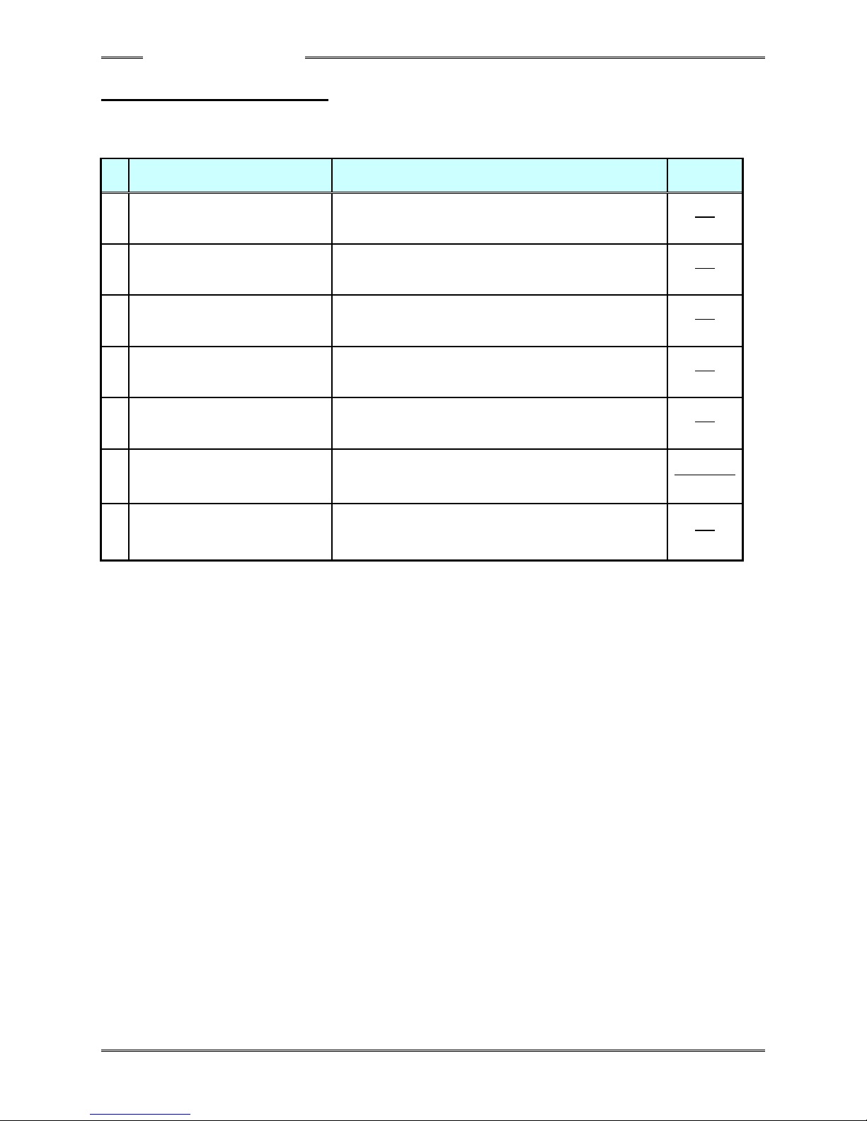
Follow the installation procedures of the Hand System in the order prescribed below.
№
Item
Contents
Page
①
Installation
Mount the controller with reference to the outer
shape.
4-2
PAGE 4-2
②
Connection of input power
source
Wiring connection by cable provided as accessory to
the controller
4-3
PAGE 4-3
③
Connection of tool cable
Connection between unit rear panel (CN1) and tool
4-4
PAGE 4-4
④
Connection of external control
signal
Connection is made only for the necessary control
signals.
4-5
PAGE 4-5
⑤
Power activation
Activate the power after checking the wiring and
checking the power source voltage.
5-1
PAGE 5-1
⑥
Set value input
The torque value, angle value, speed, timer, etc., are
set.
Chapter 6
PAGE 6-1
⑦
Initial operation check
Perform the initial operation check.
5-2
PAGE 5-2
Page 35

Chapter 4 Installation
PAGE 4-3
4-2 controller Outer Shape and Installation Dimensions
Mounting: 4 points (Rear panel) M6 screws: Use screws with a length equivalent to the installation plate
thickness +9mm.
Weight: 8.5 kg
<Mounting Precautions>
◆ Do not install the unit at a location that is constantly vibrating.
◆ Install the controller at a location where the temperature, humidity, and other operating environmental
conditions are satisfied.
◆ Do not use a mounting screw longer than the abovementioned size.
Page 36

Chapter 4 Installation
PAGE 4-4
4-3 Input Power Source Connection
Connect the dedicated power cable to the connector at a lower portion of the rear panel of the
controller.
A power cable is provided as standard.
Primary power connector
Page 37
Chapter 4 Installation
PAGE 4-5
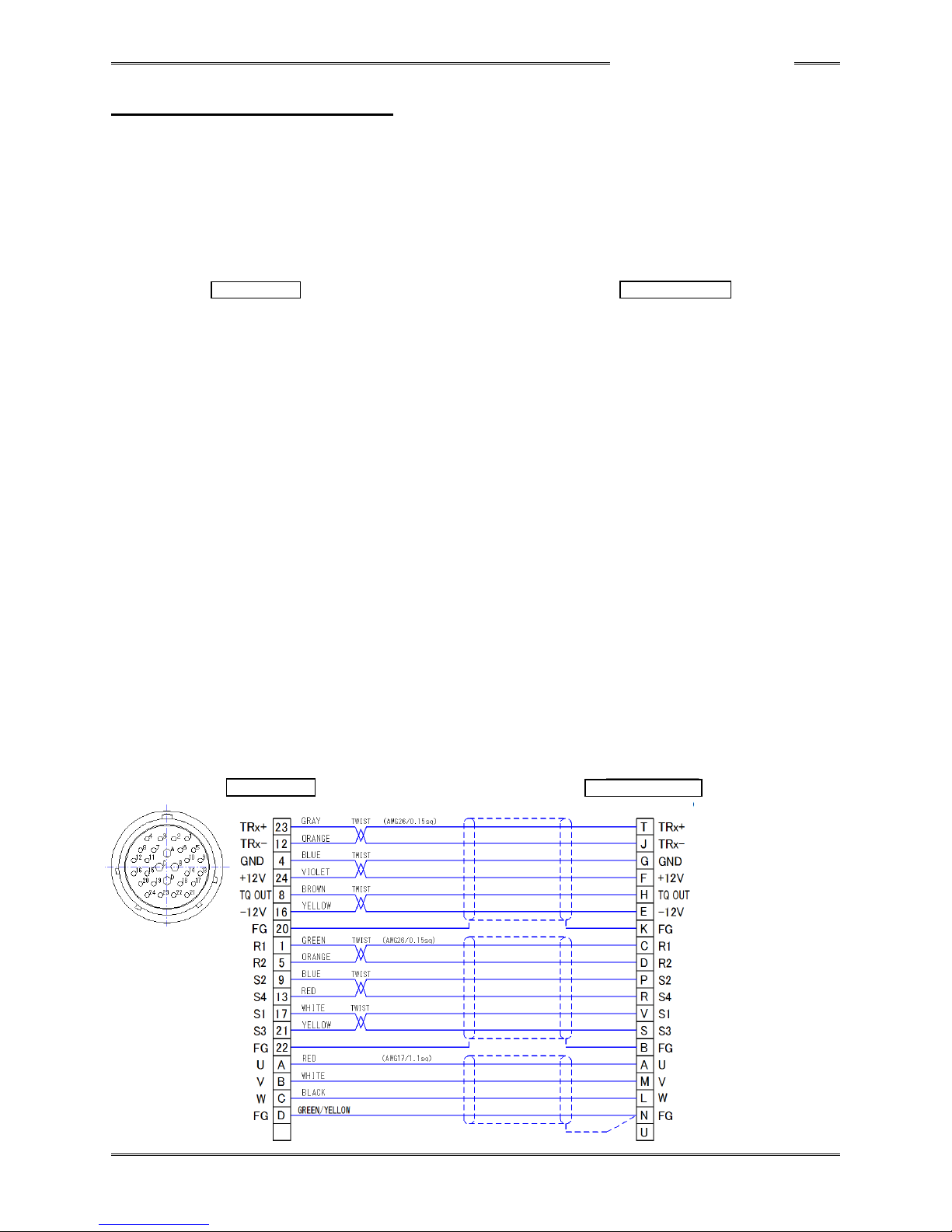
4-4 Tool Cable Specifications
■Tool Cable (Cable type: FEB-1616-M**)
■Tool Cable (Cable type: C15-F7-M**)
Tool Side
Controller side
Tool Side
Controller Side
(AWG16-4/AWG24-24)
(#22 shell-19)
Total length L
Total length L
Page 38
Chapter 4 Installation
PAGE 4-6
4-5 External Control Signal Connection
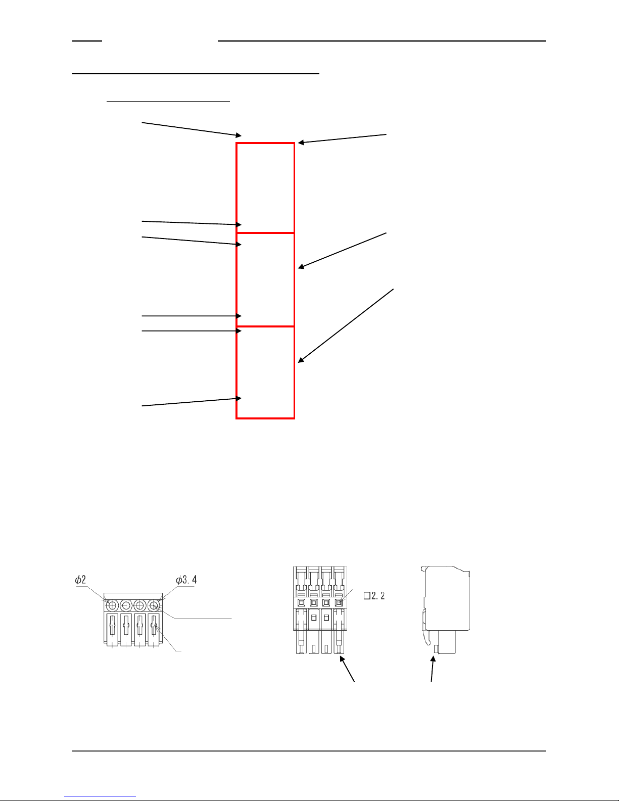
DI0 Terminal Block: TB1,2,3
TB3 12
TB3: 12 terminals
*The No. 11 terminal at the plug side lacks a
projection.
TB3 1
TB2 12 TB2: 12 terminals
TB1: 12 terminals
TB2 1 *The No. 1 terminal at the plug side lacks a
projection.
TB1 12
TB1 1
Connector Model: ML-4000-CWSH-12PGY
Manufacturer: SATO PARTS
Rated applicable wire: Solid wire 0.8mm φ (AWG 20), stranded wire 0.5mm2 (AWG 20)
Range of useable wires: Solid wire 0.4mm φ ~ 1.2mm φ (AWG 26 ~ AWG 16)
Stranded wire 0.2mm2 to 1.25mm2 (AWG 24 ~ AWG 16)
Wire outer diameter 0.18mm φ or more
Standard wire stripping length: 9mm
Note: One wire is connected to one terminal. Do not connect two or more wires to one terminal.
The No. 1 TB1 plug does not have a projection.
The No. 11 TB3 plug does not have a projection.
Wire insertion hole
Wire insertion releasing
portion
Checking hole
Page 39
Chapter 4 Installation
PAGE 4-7
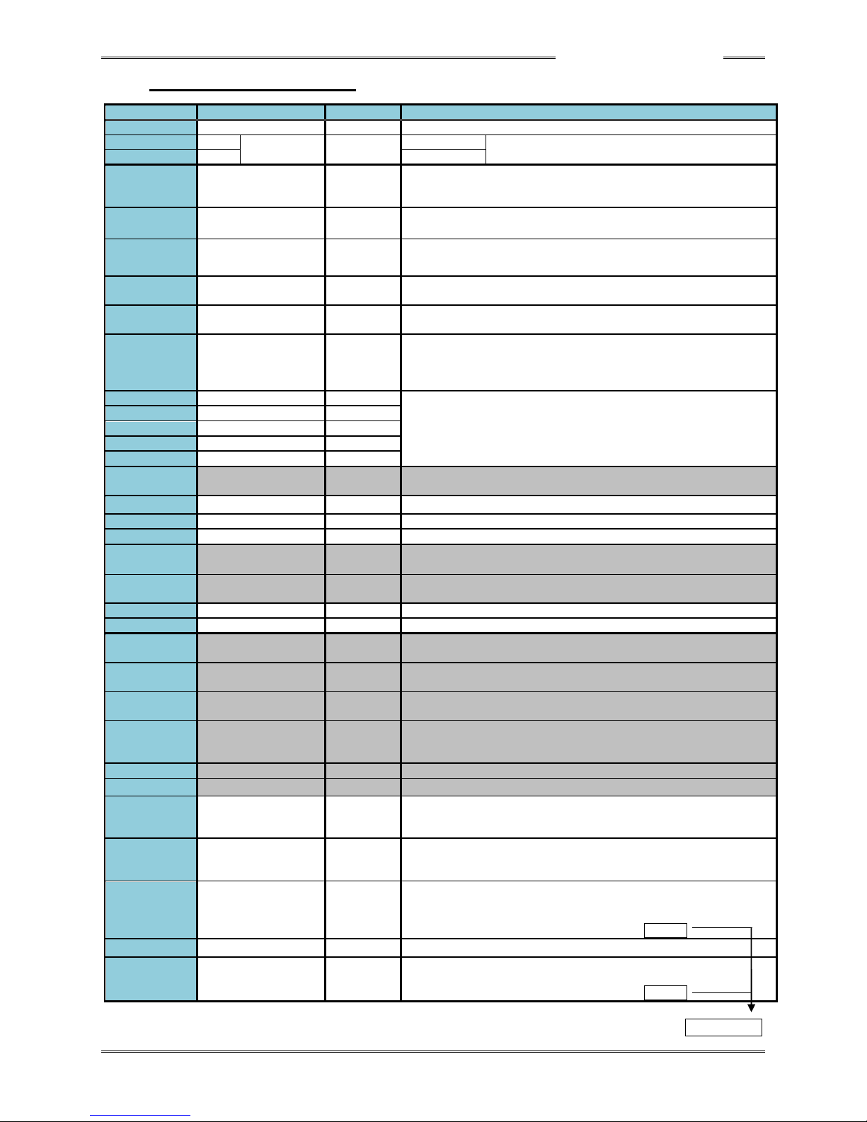
4-5-1 controller I/O Signals [BANK SELECT = OFF]
System parameter: SYS.033[xxx1xx] 0: 300ms/1: 800ms pulse length
Pin No.
Signal
IN/OUT
Description of Function/Usage
TB3-1
IN COMMON
IN
Common input signal (bipolar)
TB3-2,11
+24V
Service power
supply
0.5Amax
+24V output
When use this power supply, please use a shielding
line.Wire it from the noise source apart.
TB3-3,12
GND
GND
TB1-1
STOP
IN-1(A:NO/
B:NC)
The fastening process is stopped when this signal is set to “OFF.”
Selection between A contact and B contact is possible.
System parameter: SYS.033[xx1xxx] 0: A contact/1: B contact
TB1-2
RESET
IN-2(NO)
The fastening process is stopped and the fastening judgment of the
controller is cleared by inputting “ON.” (The ID data are cleared.)
TB1-3
REVERSE
IN-3(NO)
While “ON” is input, the tool rotates in reverse and in accordance with
the selected WORK No.
TB1e-4
START
IN-4(NO)
While “ON” is input, the fastening process is started in accordance
with the selected WORK No. (“Deadman” specification).
TB1-5
PROGRAM(BYPASS)
IN-5(NO)
The controller is put in the BYPASS (PROGRAM) mode while “ON” is
input.
TB1-6
SELF CHECK
DISABLE
IN-6(NO)
When the START signal is set to “ON” while inputting “ON” into this
pin, the self-diagnosis of the torque transducer is not performed
before the start of the fastening operation (the start of tool rotation can
be shortened by approx. 60msec).
TB1-7
WORK SELECT BIT 0
IN-7(NO)
The WORK SELECT BIT 0 ~4 select signals enable selection
among parameter Nos. 1 ~ 32 by a combination of the 5 pin Nos.
TB1-8
WORK SELECT BIT 1
IN-8(NO)
TB1-9
WORK SELECT BIT 2
IN-9(NO)
TB1-10
WORK SELECT BIT 3
IN-10(NO)
TB1-11
WORK SELECT BIT 4
IN-11(NO)
TB1-12
BANK
SELECT=[OFF]
IN-12(NO)
Bank select signal (for WORK SELECT return signal)
TB3-4
OUT COMMON
OUT
Common output signal (bipolar)
TB3-5
BATCH OK RESET
IN-13(NO)
Cycle counter (ACCEPT count) reset signal
TB3-6
IN NO
Not connected internally
TB3-7
Fastening Result
Data Available
OUT-6(NO)
Output when there are fastening result data in the controller.
TB3-8
CF CARD FULL
OUT-7(NO)
Output when capacity of the CF card is less than 1%,
or CF card isnot inserted
TB3-9
IN NO
Not connected internally
TB3-10
IN NO
Not connected internally
TB2-1
REJECT[NG]
OUT-1(NO)
Output when the fastening operation ends with a fastening result
falling outside a judgment range.
TB2-2
ACCEPT[OK]
OUT-2(NO)
Output when the fastening operation ends with the fastening
results being within the judgment ranges.
TB2-3
ABNORMAL
OUT-3(NO)
Output when an error occurs in the system or during the
fastening operation.
TB2-4
READY
OUT-4(NO)
Output when operation is enabled with respect to an input signal
from the outside. This signal is also output after the end of
fastening, regardless of the judgment.
TB2-5
BUSY
OUT-5(NO)
Output during the fastening process.
TB2-6
BYPASS
OUT-12(NO)
Output when the controller is in the BYPASS (PROGRAM) mode.
TB2-7
MANREV (RY1-1)
OUT-8(NO)
Turns ON when manually starting the reversed operation.
Turns OFF when the next fastening starts or turns OFF at RESET,
PROGRAM. (Relay contact-1)
TB2-8
BUZZER (RY2-1)
OUT-9(NO)
Performs interlocking output of REJECT signal ON/OFF to external
devices.
*However, the key click sound is not output. (Relay contact-2)
TB2-9
BATCH OK (RY3-1)
[TOTAL OK]
OUT-10(NO)
Output when the fastening results are OK for the cycle count times of
fastening (relay contact-3).
Selection between pulse and level outputs is possible.
System parameter: SYS.033[xxxx1x] 0: level/1: pulse
TB2-10
RY -COM(RY1,2,3-2)
OUT
Relay contact-1, 2, 3 common
TB2-11
TB2-12
QL OK (RY4-1)
[OK] (RY4-2)
OUT-11(NO)
OK output for QL signal (dry contact) (Relay contact-4)
Selection between pulse and level outputs is possible.
System parameter: SYS.033[xxxxx1] 0: level/1: pulse
Page 40
Chapter 4 Installation
PAGE 4-8
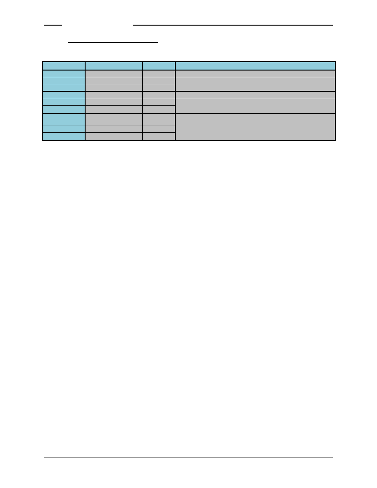
4-5-2 controller I/O Signals [BANK SELECT = ON]
The following output changes.
Pin No.
Signal
IN/OUT
Description of Function/Usage
TB1-12
BANK SELECT=[ON]
IN-12(NO)
Bank select signal (for WORK SELECT return signal)
TB3-7
WORK OUTPUT BIT 2
OUT-6(NO)
When BANK SELECT=[ON], return output of the select signals
of WORK SELECT BITS 2 and 3 is performed.
Note 1)
TB3-8
WORK OUTPUT BIT 3
OUT-7(NO)
TB2-1
WORK OUTPUT BIT 5
OUT-1(NO)
[ON] is output when any of 33 WORK to 64 WORK is selected.
TB2-2
NONE
OUT-2(NO)
[OFF] is output at all times.
TB2-3
NONE
OUT-3(NO)
TB2-4
WORK OUTPUT BIT 0
OUT-4(NO)
When BANK SELECT=[ON], return output of the select signals
of WORK SELECT BITS 0, 1, and 4 is performed.
Note 1)
TB2-5
WORK OUTPUT BIT 1
OUT-5(NO)
TB2-6
WORK OUTPUT BIT 4
OUT-12(NO)
Page 41
Chapter 4 Installation
PAGE 4-9
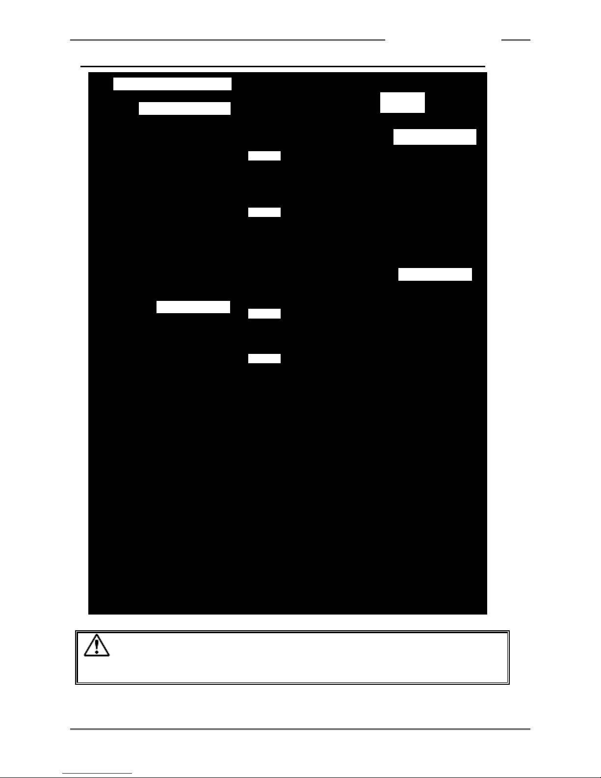
4-5-3 Input and Output Circuit Specifications and Recommended Connection Circuit
*The above diagram shows an NPN type connection example.
・The I/O hardware accommodates both positive and negative polarities and both
NPN (sink ・ - common) type and PNP (source ・ + common) type connection may
be used.
Unit I/O circuit
Input circuit
Output circuit
PLC output circuit
DC power
source
PLC input circuit
Input signal
Input signal
Caution
Output signal
Output signal
Page 42

Chapter 4 Installation
PAGE 4-10
4-5-4 Description of I/O Signals
+24V、GND: SERVICE POWER SUPPLY PIN No.: TB3-2,3,11,12
Do not supply power to the [+24V] and [GND] terminals (24V DC service power supply) on the
controller.
Doing so may cause damage to the product.Do not use it more than 0.5A. When use the service
power supply; the thing using the shield cable.Wire it from the power lines of other apparatuses apart.
Attach a clamp filter to the power supply line. (example ZCAT2032-0930:TDK)
[Input Signals]
STOP: EMERGENCY STOP SIGNAL PIN No.: TB1-1
While this signal is input in the “ON” state, the controller is put in the STOP state.
In the STOP state, the output signals are cleared and the fastening operation cannot be started.
When the STOP state is entered during the fastening operation, although the fastening operation will
be stopped, the fastening result data immediately prior to stoppage will be held.
For the “ON” state of this signal, an A contact or a B contact can be selected by the system option 1
[033].
When the A contact is selected, the signal is “OFF” in the open contact state and “ON” in the closed
contact state.
RESET: RESET SIGNAL PIN No.: TB1-2
When this signal is input in the “ON” state, the display data and the output signals of the controller are
cleared. Also, when the “ON” RESET signal is input during the fastening operation, the fastening
operation is stopped.
REVERSE: TOOL REVERSING SIGNAL PIN No.: TB1-3
While this signal is input in the “ON” state, the tool rotates in reverse.
To ensure reverse rotation of the tool, set this signal to “ON” after the READY signal is set to “ON.”
START: FASTENING START SIGNAL PIN No.: TB1-4
By this signal, the WORK SELECT 0 to 2 signals and the SELF CHECK signal are read and fastening
is started.
The rotation operation is stopped when this signal is set to “OFF.”
After the start of fastening, the controller is put in the BUSY (fastening) state.
In the following states, the READY output signal is set to “OFF” and the START signal will not be
accepted.
“During stoppage, during reverse rotation of the tool, during reset, in the BYPASS mode, and in an
abnormal state.”
When a signal corresponding to any of the above is input, the judgment signal and the previous
fastening data are reset.
BYPASS: BYPASS SIGNAL PIN No.: TB1-5
While this signal is “ON,” the controller is put in the PROGRAM mode, the BYPASS signal is output,
and fastening cannot be started.
If the BYPASS mode is entered during fastening, the fastening process is stopped.
SELF CHECK: TORQUE TRANSDUCER AUTOMATIC CHECK SIGNAL PIN No.: TB1-6
If this signal is “OFF” (or unconnected) when the START signal is input, the home-position voltage
level and the CAL voltage level of the torque transducer are automatically checked before the
fastening process.
If the automatic check of the transducer is not required, fastening without the self-check can be
performed by setting this signal to "ON" when the START signal is input.
Page 43

Chapter 4 Installation
PAGE 4-11
BATCH OK RESET: BATCH COUNTER RESET SIGNAL PIN No.: TB3-5
When a change of WORK has been selected at the terminal block, the current cycle count value is
cleared by input of this reset signal.
When a change of WORK has been selected at the controller indicator panel, the current cycle count
value is cleared by input of this reset signal. Or, after performing fastening for the set number of
times, the cycle count value is cleared automatically at the start of the next fastening process.
BANK SELECT: OUTPUT SIGNAL BANK SELECT SIGNAL PIN No.: TB1-12
The contents of the eight output signals are changed by switching ON/OFF the BANK SELECT signal.
UNUSED PIN No.: TB3-6, 9, 10
These are unused.
Page 44
Chapter 4 Installation
PAGE 4-12
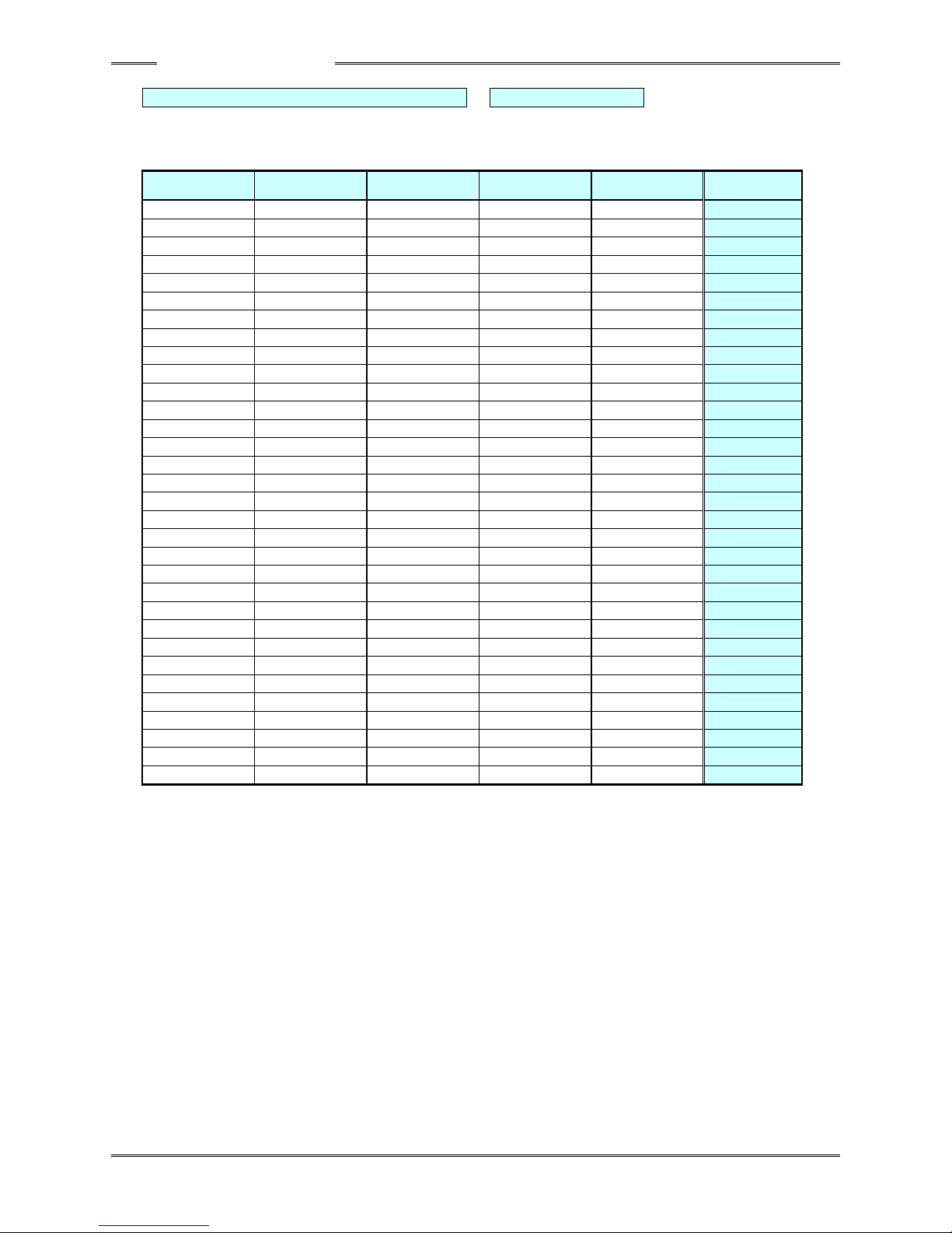
WORK SELECT 0 ~ 4: Work Select Signals PIN No.: TB1-7 ~ 11
A Work No. among 32 types can be selected by a combination of the signals WORK SELECT 0 ~
WORK SELECT 4 (selection from among 64 types of work is not accommodated).
WORK SELECT 4
PIN No.: TB1-11
WORK SELECT 3
PIN No.: TB110
WORK SELECT 2
PIN No TB1-9
WORK SELECT 1
PIN No.: TB1-8
WORK SELECT 0
PIN No.: TB1-7
WORK No.
OFF(OPEN)
OFF(OPEN)
OFF(OPEN)
OFF(OPEN)
OFF(OPEN)
1
OFF(OPEN)
OFF(OPEN)
OFF(OPEN)
OFF(OPEN)
ON
2
OFF(OPEN)
OFF(OPEN)
OFF(OPEN)
ON
OFF(OPEN)
3
OFF(OPEN)
OFF(OPEN)
OFF(OPEN)
ON
ON
4
OFF(OPEN)
OFF(OPEN)
ON
OFF(OPEN)
OFF(OPEN)
5
OFF(OPEN)
OFF(OPEN)
ON
OFF(OPEN)
ON
6
OFF(OPEN)
OFF(OPEN)
ON
ON
OFF(OPEN)
7
OFF(OPEN)
OFF(OPEN)
ON
ON
ON
8
OFF(OPEN)
ON
OFF(OPEN)
OFF(OPEN)
OFF(OPEN)
9
OFF(OPEN)
ON
OFF(OPEN)
OFF(OPEN)
ON
10
OFF(OPEN)
ON
OFF(OPEN)
ON
OFF(OPEN)
11
OFF(OPEN)
ON
OFF(OPEN)
ON
ON
12
OFF(OPEN)
ON
ON
OFF(OPEN)
OFF(OPEN)
13
OFF(OPEN)
ON
ON
OFF(OPEN)
ON
14
OFF(OPEN)
ON
ON
ON
OFF(OPEN)
15
OFF(OPEN)
ON
ON
ON
ON
16
ON
OFF(OPEN)
OFF(OPEN)
OFF(OPEN)
OFF(OPEN)
17
ON
OFF(OPEN)
OFF(OPEN)
OFF(OPEN)
ON
18
ON
OFF(OPEN)
OFF(OPEN)
ON
OFF(OPEN)
19
ON
OFF(OPEN)
OFF(OPEN)
ON
ON
20
ON
OFF(OPEN)
ON
OFF(OPEN)
OFF(OPEN)
21
ON
OFF(OPEN)
ON
OFF(OPEN)
ON
22
ON
OFF(OPEN)
ON
ON
OFF(OPEN)
23
ON
OFF(OPEN)
ON
ON
ON
24
ON
ON
OFF(OPEN)
OFF(OPEN)
OFF(OPEN)
25
ON
ON
OFF(OPEN)
OFF(OPEN)
ON
26
ON
ON
OFF(OPEN)
ON
OFF(OPEN)
27
ON
ON
OFF(OPEN)
ON
ON
28
ON
ON
ON
OFF(OPEN)
OFF(OPEN)
29
ON
ON
ON
OFF(OPEN)
ON
30
ON
ON
ON
ON
OFF(OPEN)
31
ON
ON
ON
ON
ON
32
Page 45
Chapter 4 Installation
PAGE 4-13
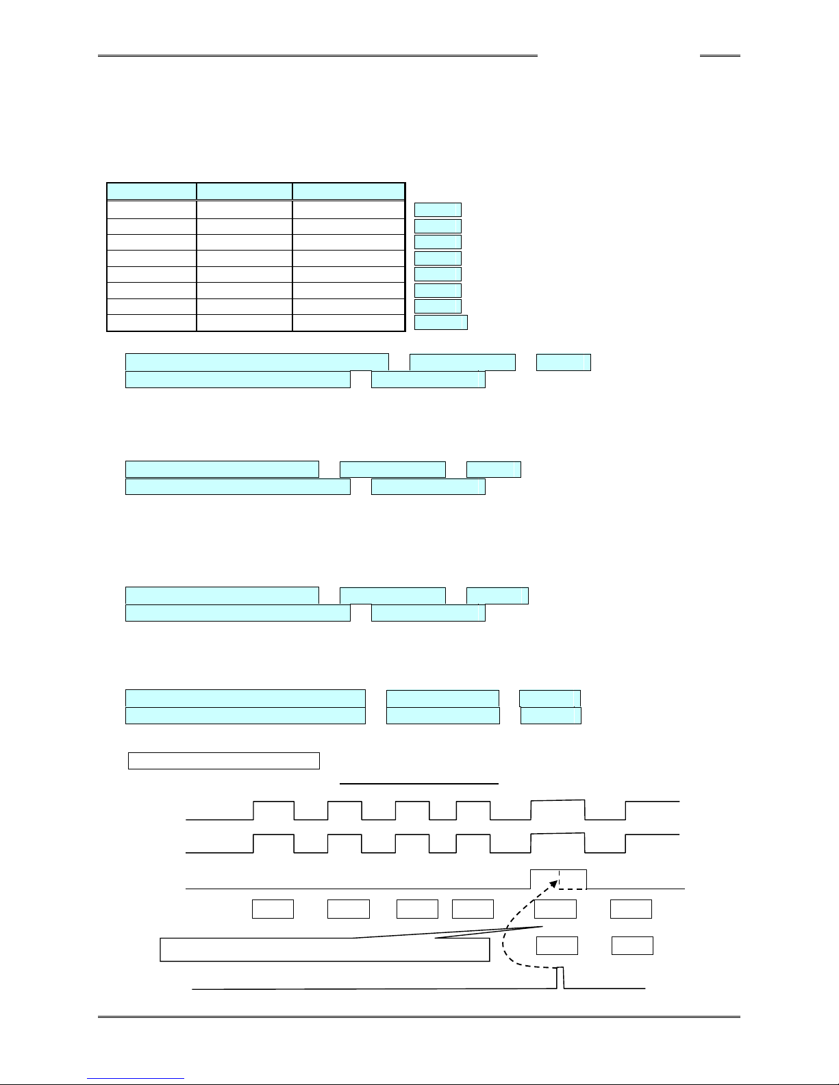
[Output Signals]
When an output signal is “ON,” the voltage at the corresponding output terminal is at the same level as
the output common voltage (0V).
As shown below, the output signal at each terminal takes on one of two meanings in accordance with the
combination with the BANK SELECT signal (output bank).
OFF: Same as the input common (HIGH) level or is open.
BANK SELECT
OFF
ON
ON: Connected to 0V.
TB2-1
REJECT(NG)
WORK SELECT 5
OUT-1
TB2-2
ACCEPT(OK)
OUT-2
TB2-3
ABNORMAL
OUT-3
TB2-4
READY
WORK SELECT 0
OUT-4
TB2-5
BUSY
WORK SELECT 1
OUT-5
TB3-7
RESULT DATA
WORK SELECT 2
OUT-6
TB3-8
CF CARD FULL
WORK SELECT 3
OUT-7
TB2-6
BYPASS
WORK SELECT 4
OUT-12
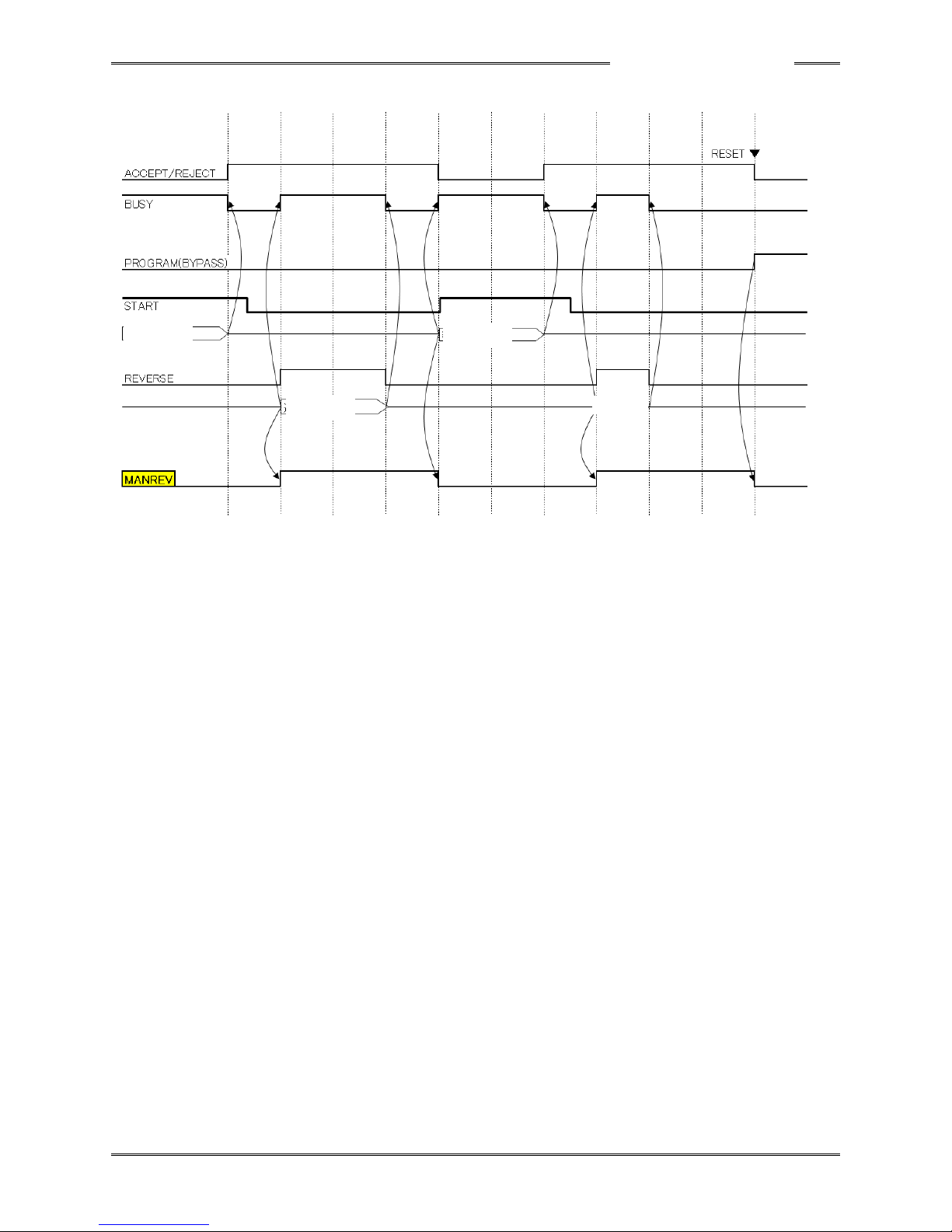
MANREV / RELAY CONTACT-1 SIGNAL PIN No.: TB2-7 OUT-8
RELAY CONTACT –COM SIGNAL PIN No.: TB2-10
Turns ON by manually starting the reversed operation.
Turns OFF when the next fastening starts, or turns “OFF” at RESET, PROGRAM.
For details, refer to PAGE4-17 [MANREV signal timing chart]
RELAY CONTACT-2 SIGNAL PIN No.: TB2-8 OUT-9
RELAY CONTACT –COM SIGNAL PIN No.: TB2-10
Performs interlocking output of REJECT signal ON/OFF to external devices. (Click sound of the
operation switch is not output.)
Turns ON for 0.4 seconds by the BATCH OK signal rise-up.
Turns ON for 0.1 seconds by the QL OK signal rise-up.
RELAY CONTACT-3 SIGNAL PIN No.: TB2-9 OUT-10
RELAY CONTACT –COM SIGNAL PIN No.: TB2-10
OK is output when the fastening has been performed for the number of times specified by the cycle
count.
QL OK RELAY CONTACT-4 SIGNAL PIN No.: TB2-11 OUT-11
QL OK RELAY CONTACT-4 SIGNAL PIN No.: TB2-12 OUT-11
OK output for the QL signal
[QL OK] [BATCH OK] Timing Chart
D-No.540: Cycle count = 5
ACCEPT
QL OK
BATCH OK
D-No/COUNT
BATCH OK RESET
c01 c02 c03 c04 c05 → c01
↓
c00 → c01
Clear at BATCH OK RESET, count starts after “c00”.
Page 46

Chapter 4 Installation
PAGE 4-14
NG: FASTENING NG (FAILURE) SIGNAL PIN No.: TB2-1 OUT-1
The “ON” output is performed when an abnormal exit occurs with a fastening result falling outside a
judgment range.
OK: FASTENING OK SIGNAL PIN No.: TB2-2 OUT-2
The “ON” output is performed when normal exit is accomplished with the fastening results being
within the judgment ranges.
ABNORMAL: SYSTEM ERROR/ABNORMAL EXIT PIN No.: TB2-3 OUT-3
The “ON” output is performed when an error is detected during the system check performed by the
controller or during the fastening process.
When an error occurs, fastening is stopped immediately and the fastening results data are stored.
READY: INPUT ENABLING SIGNAL PIN No.: TB2-4 OUT-4
The “ON” output is performed when operation fastening, reverse rotation, etc., can be performed by
an input signal from the PLC or other external equipment.
The READY signal is “OFF” under the following conditions.
◎During the initialization process in power activation
◎During reverse rotation
◎When the ABNORMAL signal is output
◎In the BYPASS mode (during settings, in the download mode (during communication), etc.)
◎In the STOP state
◎During fastening, reset, or CAL check
◎Other conditions where operation of the controller by an external output is disabled
BUSY: SIGNAL DURING FASTENING PIN No.: TB2-5 OUT-5
The “ON” output is performed when the controller is performing the fastening process.
Fastening Result Data Available PIN No.: TB3-7 OUT-6
The “ON” output is performed when fastening result data are present.
CF CARD FULL PIN No.: TB3-8 OUT-7
The “ON” output is performed when capacity of the CF card is less than 1%, or CF card isnot inserted
BYPASS: BYPASS MODE PIN No.: TB2-6 OUT-12
The “ON” output is performed in the BYPASS mode.
OUTPUT BANK [OFF]
Page 47
Chapter 4 Installation
PAGE 4-15
UNUSED PIN No.: TB2-2, TB2-3 OUT-2~3
These are unused.
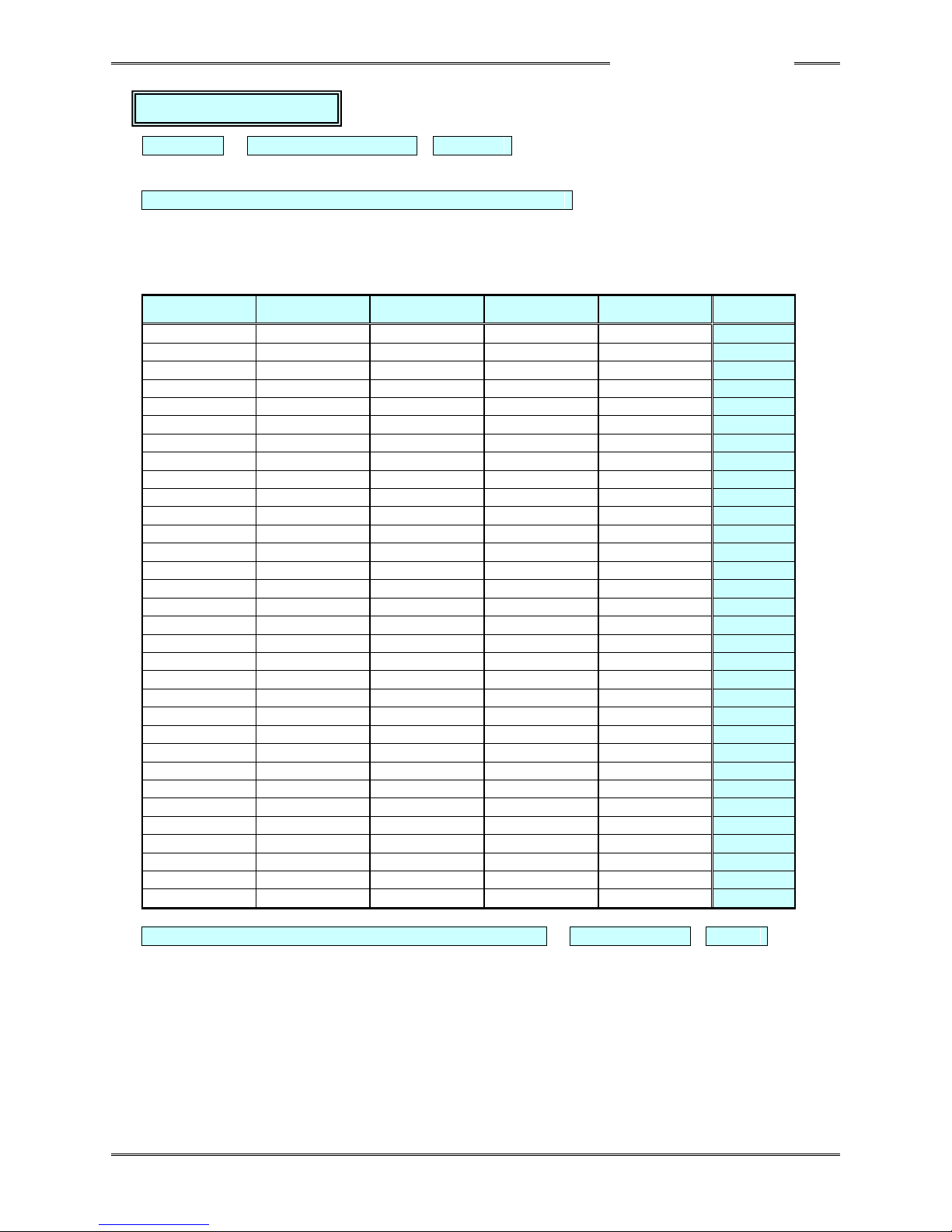
WORK OUTPUT 0 ~ 4: WORK SELECTION INPUT CHECK
The input signals, WORK SELECT 0 ~ 4, are returned as they are as the output signals, WORK
OUTPUT 0 ~ 4.
These are used to confirm matching with the work selection that is input.
WORK OUTPUT 4
PIN No.: TB2-6
WORK OUTPUT 3
PIN No.: TB3-8
WORK OUTPUT 2
PIN No.: TB3-7
WORK OUTPUT 1
PIN No.: TB2-5
WORK OUTPUT 0
PIN No.: TB2-4
WORK No.
OFF(OPEN)
OFF(OPEN)
OFF(OPEN)
OFF(OPEN)
OFF(OPEN)
1
OFF(OPEN)
OFF(OPEN)
OFF(OPEN)
OFF(OPEN)
ON
2
OFF(OPEN)
OFF(OPEN)
OFF(OPEN)
ON
OFF(OPEN)
3
OFF(OPEN)
OFF(OPEN)
OFF(OPEN)
ON
ON
4
OFF(OPEN)
OFF(OPEN)
ON
OFF(OPEN)
OFF(OPEN)
5
OFF(OPEN)
OFF(OPEN)
ON
OFF(OPEN)
ON
6
OFF(OPEN)
OFF(OPEN)
ON
ON
OFF(OPEN)
7
OFF(OPEN)
OFF(OPEN)
ON
ON
ON
8
OFF(OPEN)
ON
OFF(OPEN)
OFF(OPEN)
OFF(OPEN)
9
OFF(OPEN)
ON
OFF(OPEN)
OFF(OPEN)
ON
10
OFF(OPEN)
ON
OFF(OPEN)
ON
OFF(OPEN)
11
OFF(OPEN)
ON
OFF(OPEN)
ON
ON
12
OFF(OPEN)
ON
ON
OFF(OPEN)
OFF(OPEN)
13
OFF(OPEN)
ON
ON
OFF(OPEN)
ON
14
OFF(OPEN)
ON
ON
ON
OFF(OPEN)
15
OFF(OPEN)
ON
ON
ON
ON
16
ON
OFF(OPEN)
OFF(OPEN)
OFF(OPEN)
OFF(OPEN)
17
ON
OFF(OPEN)
OFF(OPEN)
OFF(OPEN)
ON
18
ON
OFF(OPEN)
OFF(OPEN)
ON
OFF(OPEN)
19
ON
OFF(OPEN)
OFF(OPEN)
ON
ON
20
ON
OFF(OPEN)
ON
OFF(OPEN)
OFF(OPEN)
21
ON
OFF(OPEN)
ON
OFF(OPEN)
ON
22
ON
OFF(OPEN)
ON
ON
OFF(OPEN)
23
ON
OFF(OPEN)
ON
ON
ON
24
ON
ON
OFF(OPEN)
OFF(OPEN)
OFF(OPEN)
25
ON
ON
OFF(OPEN)
OFF(OPEN)
ON
26
ON
ON
OFF(OPEN)
ON
OFF(OPEN)
27
ON
ON
OFF(OPEN)
ON
ON
28
ON
ON
ON
OFF(OPEN)
OFF(OPEN)
29
ON
ON
ON
OFF(OPEN)
ON
30
ON
ON
ON
ON
OFF(OPEN)
31
ON
ON
ON
ON
ON
32
WORK OUTPUT 5: WORK SELECTION INPUT CHECK PIN No.: TB2-1 OUT-1
This output signal is set to “ON” while a work among work Nos. 33 ~ 64 is selected.
Although the selection among the work Nos. 33 ~ 64 cannot be made using the [WORK SELECT]
input signals, WORK OUTPUT 5 can be used when a selection is made from the operation panel or
from a Fieldbus interface.
OUTPUT BANK [ON]
Page 48
Chapter 4 Installation
PAGE 4-16
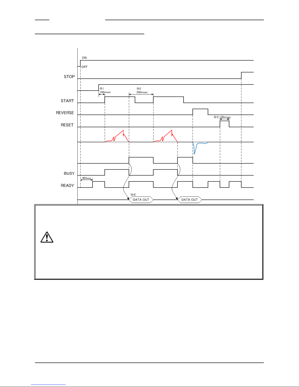
4-5-5 Input/output signal timing chart
●Basic control signals
*1) WORK SELECT requires a response time of 100 msec or more after the READY signal
ON is output until the START signal is input.
*2) After the fastening operation completes, a waiting time of 200 msec or more is
required to input the next START signal. If the START signal is continually input, it may
not be accepted.
*3) To input the RESET signal or the STOP signal, input time of 100 msec or more is
required. If the signal is continually input, it may not be accepted.
*4) When the fastening operation completes, the RS 232C data communication output is
performed only once for approximately 90 msec.
To acquire the fastening result data to a PC, start the communication by the START
signal input timing (BUSY signal ON).
Caution
Input signal
Output signal
RS232C Output
Torque Curve
Axis Judgment
Work Select
Controller Power
Page 49
Chapter 4 Installation
PAGE 4-17
●MANREV signal timing chart
BANK Output
Reverse
Reverse
Fastening
Fastening
Page 50
Chapter 4 Installation
PAGE 4-18
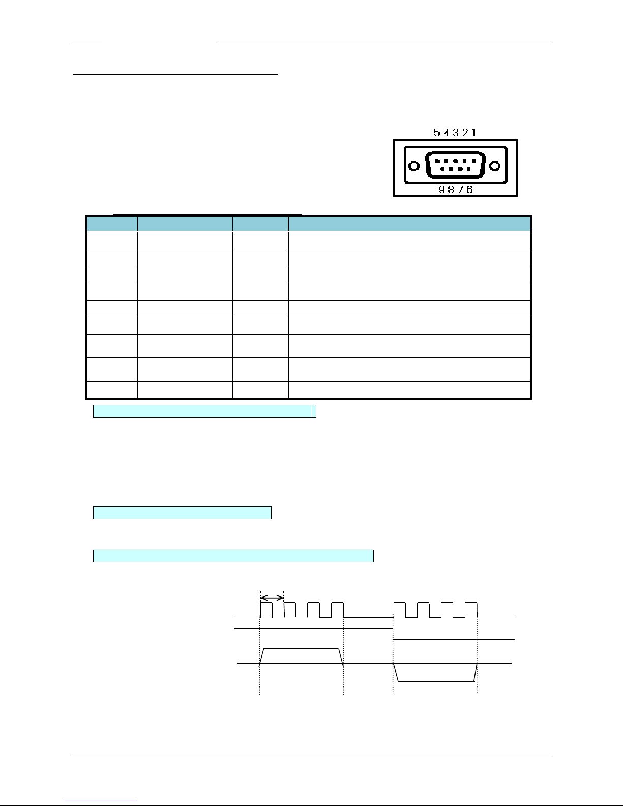
4-6 External Monitoring Device Signal
External monitor signals are output from the MONITOR connector on the controller bottom.
Compatible connector
D-SUB 9-pin plug Inch thread (#4-40)
External monitor signal specifications
Pin No.
Signal
IN/OUT
Description
1
EA2
OUT
Disabled
2
EB2
OUT
Disabled
3
ANGLE PULSE
OUT
Angle pulse monitor output
4
ANGLE CW/CCW
OUT
Normal/reverse monitor output
5
GND
-
Monitor signal output GND
6
TD2
OUT
Disabled
7
MON1
OUT
Current monitor output (10V: controller maximum
current)
8
MON2
OUT
Speed monitor output
(10V: Tool maximum rotation speed)
9
TORQUE OUT
OUT
Torque analog voltage monitor output
TORQUE OUT: Torque Analog Voltage Signal
With the monitor voltage, the range from the ZERO voltage to the CAL voltage at the calibration
torque is expressed by a potential difference of approximately 3.75V. The ZERO voltage is the
voltage in the state where the tool is stopped. *The ZERO voltage is not 0V (within a range of -0.1V
~ +0.1V). Also, even among tools of the same model, the ZERO voltage differs according to each
tool.
(Example) If the ZERO voltage is -0.03V, the CAL voltage at the calibration torque is +3.72V and the
voltage change is Δ3.75V.
ANGLE PULSE: Angle Pulse Signal (5V TTL signal)
As the angle pulse, 1 pulse is output per 1 degree.
*There is some error with respect to the actual rotation angle (1 rotation of the tip: 358 ~ 362 pulses).
ANGLE CW/CCW: Normal/Reverse Rotation Pulse Signal (5V TTL signal)
A HI signal is output when the motor is rotating in the normal direction and a LOW signal is output
when the motor is rotating in reverse.
Angle Pulse Signal
1deg
Normal/Reverse Signal
Operation State
Normal Rotation
MONITOR
Suspension
Suspension
Reverse Rotation
Page 51
Chapter 4 Installation
PAGE 4-19
How to Calibrate the External Monitoring Device
When the CAL switch of the controller indicator is pressed while “1” is indicated at the D-No. indication part
of the indicator in the real time mode, the CAL voltage is output at a potential difference of approximately
Δ3.75V from TORQUE OUT and, at the same time, the torque value recognized by the controller is indicated
at the upper indication part. Adjust the torque voltage at the external monitoring device so that the same
torque value is displayed.
*The ZERO voltage in the no-load state is not 0V. The ZERO voltage value differs according to each
controller and tool and correction at the external monitoring device is thus required.
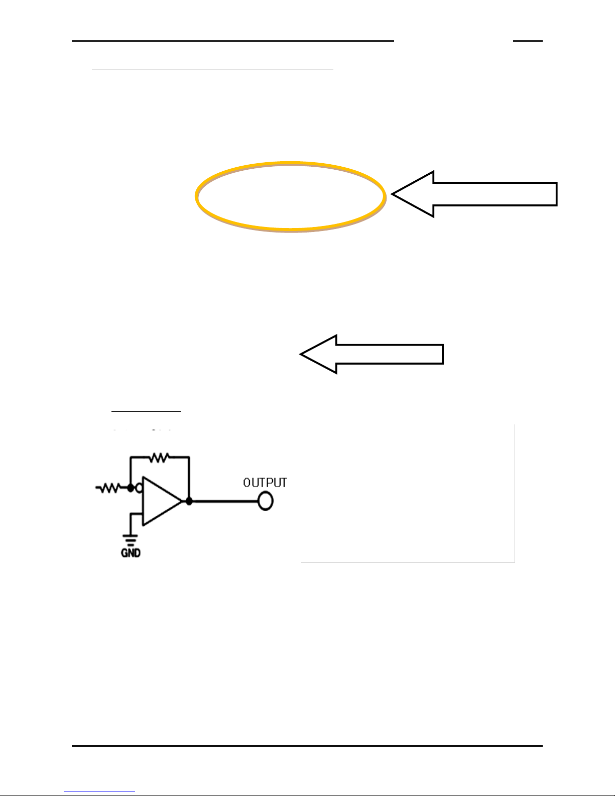
Output Circuit
●Torque, Current, Speed Voltage Output Part ●Angle Pulse, Normal/Reverse Output Part
The CAL voltage value is indicated at the
upper indication part.
Press the CAL switch.
Op amp output: 0 ~ ±5V
TTL (5V) output
Page 52
Chapter 4 Installation
PAGE 4-20
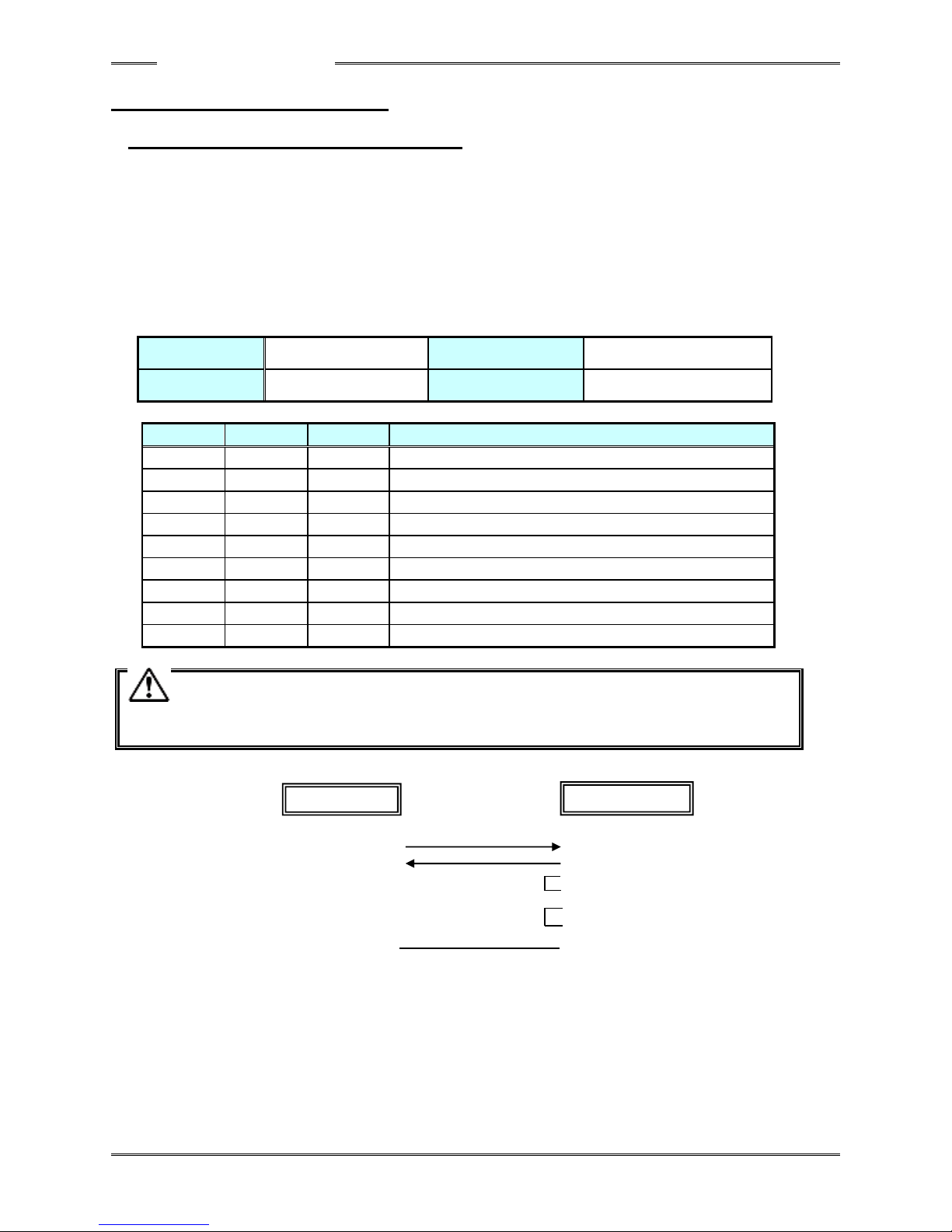
4-7 RS-232C Interface Signal
4-7-1 RS232C Specifications (RS232C-1)
Compatible connector
D-SUB 9-pin socket Inch thread (#4-40)
RS232C Communication Specifications
Synchronization
Method
Start-stop
synchronization method
Communication
Speed
9600bps (fixed)
Communication
Mode
Half-duplex system
Data Length/Start
Bit/Parity/Stop
8 bits/1 bit/None/2 bits (fixed)
Pin No.
Signal
IN/OUT
Details
1
NC
-
Not used
2
RXD
IN
Not used
3
TXD
OUT
Operation result data output
4
DTR
OUT
Always ON output
5
GND
-
Signal ground
6
NC
-
Not used
7
RTS
OUT
Always ON output
8
NC
-
Not used
9
NC
-
Not used
・Be sure to clear the PLC receive buffer when the control power of the controller is
activated. Output of garbage data due to the effects of noise, etc., may cause data
deviation.
●Connection Diagram
D-SUB 9-pin socket D-SUB 25-pin plug (9-pin socket)
TXD 3 3(2) RXD (result data output)
RXD 2 2(3) TXD (not used)
DTR 4 20(4) DTR
6(6) DSR
RTS 7 4(7) RTS
5(8)CTS
GND 5 7(5) GND
RS232C-1
Caution
Equipment Side
Unit Side
Page 53
Chapter 4 Installation
PAGE 4-21
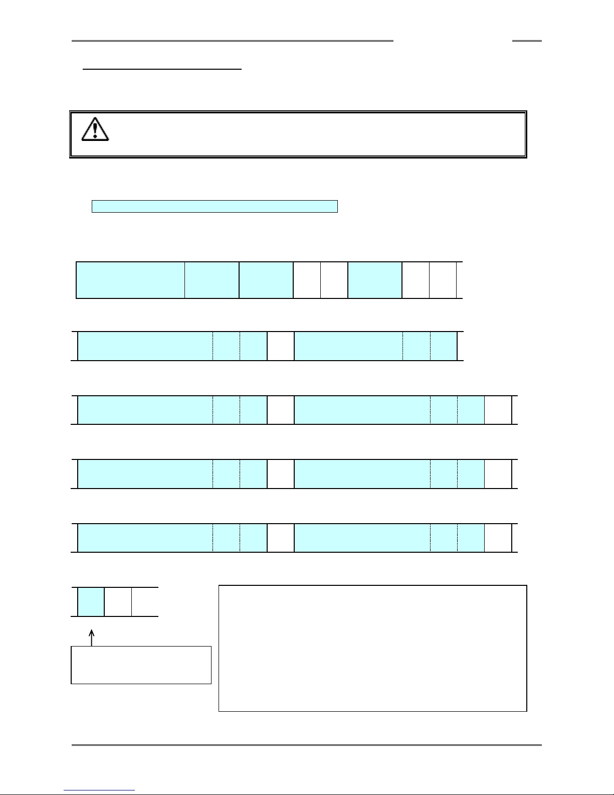
4-7-2 Data Format (RS232C-1)
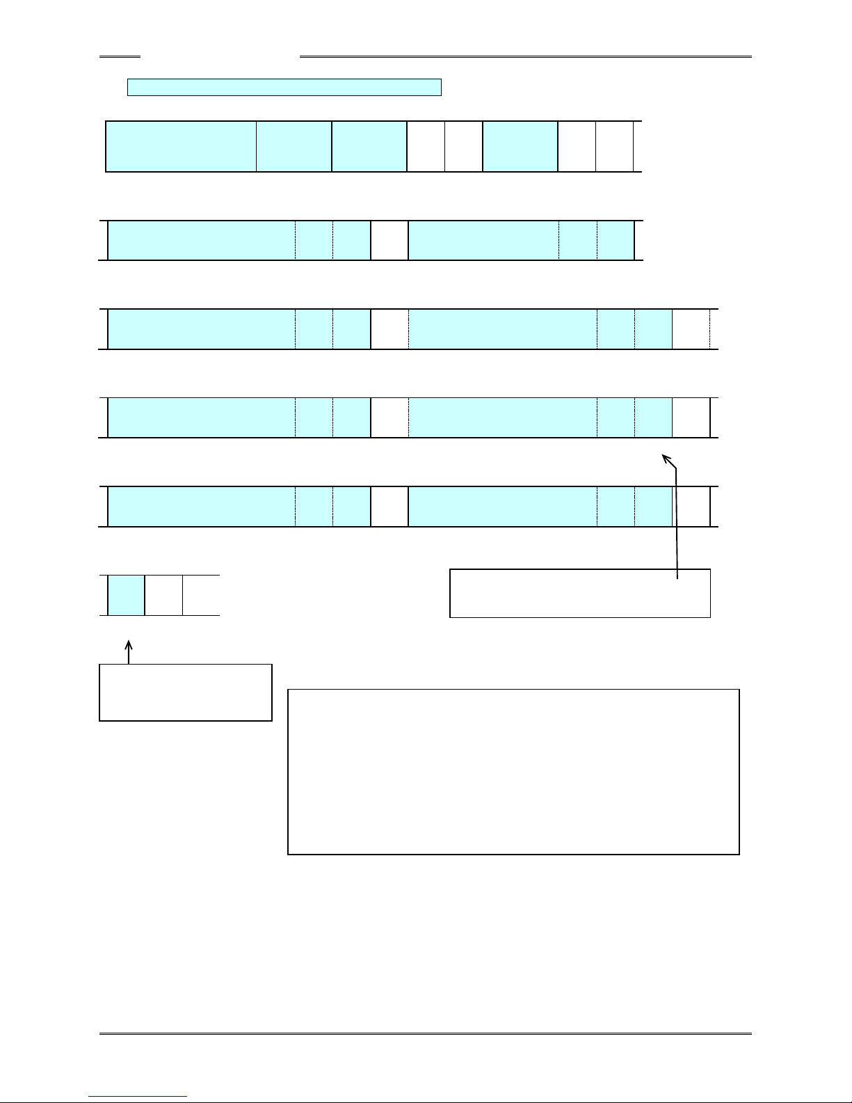
The fastening result data are output from the RS232C-1 interface at the end of fastening. The data
length of the fastening result data in ASCII format is 79 bytes (corresponding to 79 characters) per
single fastening operation. The format of the data output per Axis is shown below.
・ Be careful because the decimal point differs according to tool model.
・ The output data of each item are indicated in a right-justified manner.
●Output Data Format (in the case of ASCII format, with torque being indicated to 2 decimal places and the
rate is indicated to 3 decimal places)
When the fastening judgment is normal (ACCEPT)
COUNT No. : Incremented by +1 at each fastening (stored even when power is shut down, reset in linkage
with erasing of 10,000 records)
ACCEPT COUNT: Counted number of ACCEPT fastening judgments (JDG: Judgment, OCR: Occurrence)
1 2 3 4 5 6 7 8 9 10 11 12 13 14
COUNT No.
ACCEPT
COUNT
AXIS No.
WORK No.
30H 30H 30H 31H
30H 31H
30H 31H
20H
20H
30H 31H
20H
20H
0 0 0 1 0 1 0 1 0 1
15 16 17 18 19 20 21 22 23 24 25 26 27 28
PEAK TORQUE
JDG
OCR
FINAL ANGLE
JDG
OCR
31H 32H 2EH 33H 34H
20H
20H
20H
20H 31H 32H 33H
20H
20H
1 2 . 3 4 1 2 3
29 30 31 32 33 34 35 36 37 38 39 40 41 42 43 44
FINAL TORQUE
JDG
OCR
RATE1
JDG
OCR
31H 32H 2EH 33H 34H
20H
20H
20H
30H 2EH 31H 32H 33H
20H
20H
20H
1 2 . 3 4 0 . 1 2 3
45 46 47 48 49 50 51 52 53 54 55 56 57 58 59 60
RATE2
JDG
OCR
RATE3
JDG
OCR
30H 2EH 31H 32H 33H
20H
20H
20H
30H 2EH 31H 32H 33H
20H
20H
20H
0 . 1 2 3 0 . 1 2 3
61 62 63 64 65 66 67 68 69 70 71 72 73 74 75 76
1ST TIME
JDG
OCR
2ND TIME
JDG
OCR
20H 31H 30H 2EH 30H
20H
20H
20H
20H 20H 32H 2EH 30H
20H
20H
20H
1 0 . 0 2 . 0
77 78 79
JDG
CR
LF
4FH
0DH
0AH
O
TOTAL JUDGMENT
"O"(4FH): Fastening judgment
ACCEPT
[PEAK TORQUE] JUDGMENT
"H"(48H): HIGH REJECT "L"(4CH): LOW REJECT
"A"(41H): ABNORMAL "S"(53H): STOP
"B"(42H): BYPASS “R”(52H): RESET
“D” (44H): START OFF (Off operation by lever performed during
fastening)
The CAUSE OF REJECT OCR (OCR) is not set in the case of solitary
occurrence of "A," "B," "S," “R,” or “D.”
[FINAL TORQUE], [ANGLE], [RATE], [TIME] JUDGMENT
"H"(48H): HIGH REJECT "L"(4CH): LOW REJECT
Caution
Page 54
Chapter 4 Installation
PAGE 4-22
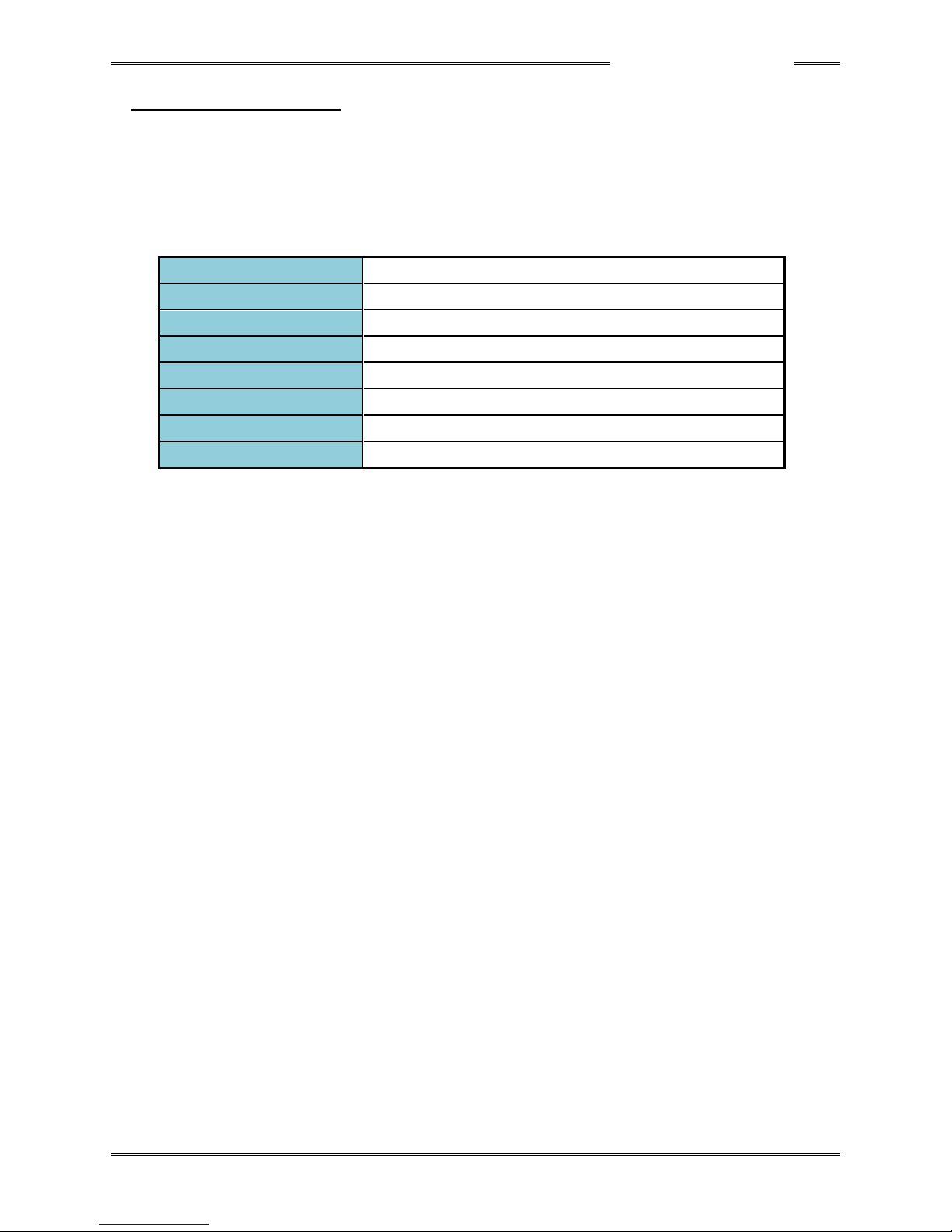
When the fastening judgment is NG (REJECT) (JDG: Judgment, OCR: Occurrence)
1 2 3 4 5 6 7 8 9 10 11 12 13 14
COUNT No.
ACCEPT
COUNT
AXIS No.
WORK No.
30H 30H 30H 31H
39H 39H
30H 31H
20H
20H
30H 31H
20H
20H
0 0 0 1 9 9 0 1 0 1
15 16 17 18 19 20 21 22 23 24 25 26 27 28
PEAK TORQUE
JDG
OCR
FINAL ANGLE
JDG
OCR
20H 31H 2EH 32H 33H
4CH
20H
20H
20H 20H 35H 30H
4CH
20H
1 . 2 3 L 5 0 L
29 30 31 32 33 34 35 36 37 38 39 40 41 42 43 44
FINAL TORQUE
JDG
OCR
SIGN
RATE1
JDG
OCR
SIGN
20H 31H 2EH 32H 33H
4CH
20H
20H
30H 2EH 31H 32H 33H
20H
20H
20H
1 . 2 3 L 0 . 1 2 3
45 46 47 48 49 50 51 52 53 54 55 56 57 58 59 60
RATE2
JDG
OCR
SIGN
RATE3
JDG
OCR
30H 2EH 31H 32H 33H
20H
20H
20H
31H 2EH 31H 32H 33H
48H
58H
20H
0 . 1 2 3 1 . 1 2 3 H X
61 62 63 64 65 66 67 68 69 70 71 72 73 74 75 76
1ST TIME
JDG
OCR
2ND TIME
JDG
OCR
20H 31H 30H 2EH 30H
20H
20H
20H
20H 20H 32H 2EH 30H
20H
20H
20H
1 0 . 0 2 . 0
77 78 79
JDG
CR
LF
58H
0DH
0AH
X
CAUSE OF REJECT OCR
“X” (58H):This is set behind the data for
which the REJECT judgment was made first.
[PEAK TORQUE] JUDGMENT
"H"(48H): HIGH REJECT "L"(4CH): LOW REJECT
"A"(41H): ABNORMAL "S"(53H): STOP
"B"(42H): BYPASS “R”(52H): RESET
“D” (44H): START OFF (Off operation by lever performed during fastening)
The CAUSE OF REJECT OCR (OCR) is not set in the case of solitary
occurrence of "A," "B," "S," “R,” or “D.”
[FINAL TORQUE], [ANGLE], [RATE], [TIME] JUDGMENT
"H"(48H): HIGH REJECT "L"(4CH): LOW REJECT
TOTAL JUDGMENT
"X"(58H): Fastening
judgment REJECT
Page 55
Chapter 4 Installation
PAGE 4-23
4-8 Ethernet Interface
The Ethernet interface is the TCP/IP Ethernet port dedicated to communication with the HFC3000
User Console installed in a PC with Windows®.
A commercially available LAN cable (cross/straight) can be used as the cable.
The following factory settings are set as the TCP/IP settings of the controller. The settings at the PC
side must thus be changed when first connecting to the PC.
IP address
192.168.11.10 (factory setting)
Subnet Mask
255.255.255.0(factory setting)
Default Gateway
192.168.11.1 (factory setting)
Communication Protocol
IEEE 802.3 compliant
Ethernet Standard
100BASE-T
Communication Speed
100Mbps
Cable
Category 5 or higher (category 5 is recommended)
Connector Shape
RJ-45
Page 56

Chapter 4 Installation
PAGE 4-24
Memo
Page 57

Chapter 5 Power Activation and Operational Tests
PAGE 5-1
Chapter 5 Power Activation and
Operational Tests
5
Page 58
Chapter 5 Power Activation and Operational Tests
PAGE 5-2
5-1 Items to be Checked Before Power Activation
(1) Check connection between tool and Controller
Connect the cable between the tool and the controller securely.
If there is a movable part in the path of the cable, check whether or not the cable receives stress by
actually moving the movable part. If the cable receives stress, change the wiring method.
(2) Check wiring for I/O signals
Connection with the external control equipment must be made at the terminal block on the rear panel
of the controller.
(3) Use a dedicated cable for power source.
Check that the earth line is connected without fail.
(4) Check the power source voltage
Check that the input power source voltage of the controller is in a range of single-phase 100V AC ~
240V AC.
The recommended wiring size for the primary power is no less than 1.25mm2. If lowering of the
power source voltage occurs due to using a thin wiring, etc., a source voltage error will occur.
Lowering of voltage may occur if a thin wire is used across a long distance.
BE SURE TO CONFIRM THE ABOVE ITEMS BEFORE POWER ACTIVATION.
There is danger of fault or electric shock.
Caution
Page 59
Chapter 5 Power Activation and Operational Tests
PAGE 5-3
5-2 Items to be Checked When Activating the Equipment
Confirm that the indications on the indicator change as follows when the control power is activated.
If “ABN” is indicated at the upper stage of the indicator when the power is activated, please refer to
“Description/Cause of Abnormal State and Recovery Method” to eliminate the cause, ensure safety,
and then reactivate the control power.
Also, check the following safety precautions when activating the power.
<Safety Precautions in Reactivating the Power>
If the power is to be reactivated, be sure to wait for a waiting time (recommended: 1 minute) after the
power has been turned OFF and then turn ON the power. The following problems may occur if there is no
waiting time or if reactivation is performed in a short time.
・An abnormal current may flow to the primary power source circuit without operation of the rush current
prevent circuit and the circuit protector which protects the circuit may therefore be put in an interrupted
state.
・The Controller power source circuit may detect an error and automatically interrupt the circuit. As a
result, the power source circuit will not operate (remains OFF) even when the power is reactivated.
If the power cannot be reactivated, be sure to wait for 5 minutes or more after turning OFF the power and
then turn ON the power.
RUN Mode
All segments are lit for
approx. 3 seconds
Power activation
PROGRAM Mode
Page 60

Chapter 5 Power Activation and Operational Tests
PAGE 5-4
5-3 Input Initial Setting Data
After checking all of the check items of the previous section and activating the power, input the data
necessary for performing fastening. Although initial setting data based on the customer’s
specifications are input at the time of shipment, if the setting data need to be changed, please refer
to “Chapter 6 Description of Operations.”
5-4 Items to be Checked After Activation
Perform the following checks after activating the power.
(1) Check ZERO Value
Press the RESET switch on the controller and confirm that a value close to zero is indicated as the
torque value on the controller. Also confirm that NG LED (red) does not light up at this point.
(2) Check CAL Value
Press the CAL switch on the controller and confirm that NG LED (red) does not light up.
(3) Check Rotation
Press the start switch on the tool to make the tool rotate and confirm that there is no abnormal noise
or rotational vibration, etc.
The tool should rotate only when the start switch is pressed and stop when the switch is released.
(4) Check Reverse Rotation
Press the reversing switch on the tool and confirm that the judgment LED flahses.
Then press the start switch. Reverse rotation should be performed while the switch is pressed.
Press the reversing switch again to put the tool in the fastening mode.
Page 61

Chapter 6 Description of Operations
PAGE 6-1
Chapter 6 Description of Operations
6
Page 62

Chapter 6 Description of Operations
PAGE 6-2
6-1 Changing between RUN and PROGRAM Modes
There are two modes to the Handheld tool - the RUN (operation) and PROGRAM (setting) modes.
In the RUN (operation) mode, the fastening operation and the fastening result judgment are indicated.
Parameters can be changed in the PROGRAM (setting) mode.
Changing between the RUN and PROGRAM modes can be performed by the PLC I/F BYPASS signal
or the PRG key switch (long-pressing for 1.5 seconds).
Page 63

Chapter 6 Description of Operations
PAGE 6-3
(1) Operation/Check Switches
①CAL key switch: CAL voltage check
When this switch is pressed, a check of the torque transducer of the tool is performed.
The calibration torque value is indicated at the “DATA” indication part.
If as a result of the check, the value is within the specified ranges, the LED of the tool flahses alternately
in green <--> orange.
If as a result of the check, the value falls outside the specified range, the LED of the tool flahses
alternately in orange <--> red.
②RST key switch
This is used to reset the Axis controller.
When this is pressed during fastening, the fastening is interrupted and all output signals are reset.
At the same time, the home position voltage of the torque transducer is indicated.
③PRG key switch: Operation/setting changeover switch
Each time this switch is long-pressed for 1.5 seconds, a mode change between the operation (RUN)
and setting (PROGRAM) modes is performed alternately.
(2) Indication LEDs
①OK LED Green [QL OK]
This lights up when the fastening ends with all results being within the various setting ranges.
When the TOTAL OK LED lights up, this LED is OFF.
②NG LED Red [NG]
This lights up when the fastening ends with a result falling outside any of the various setting ranges.
This lights up when a system error occurs (The abnormality No. is indicated on data indication part).
③TOTAL OK LED Green [TOTAL OK]
This lights up when the results of the fastening operations of the designated number of times (cycle
count) are all OK.
④Torque LED Green [TORQUE]
This lights up when the DATA content is a torque value.
⑤Angle LED Green [ANGLE]
This lights up when the DATA content is an angle value.
(3) Switches for Data Indication Operations
①SET key
This is used to finalize an indication or finalize data.
②Cursor keys [△][▼]
These are used to scroll the indicated data and to change setting data.
These are used to change WORK No. in the operation view mode.
However, these functions cannot be used while an abnormality is occurring.
③Cursor keys [◄][►]
These are used to change the mode and to move the cursor (flashing indication position).
Page 64
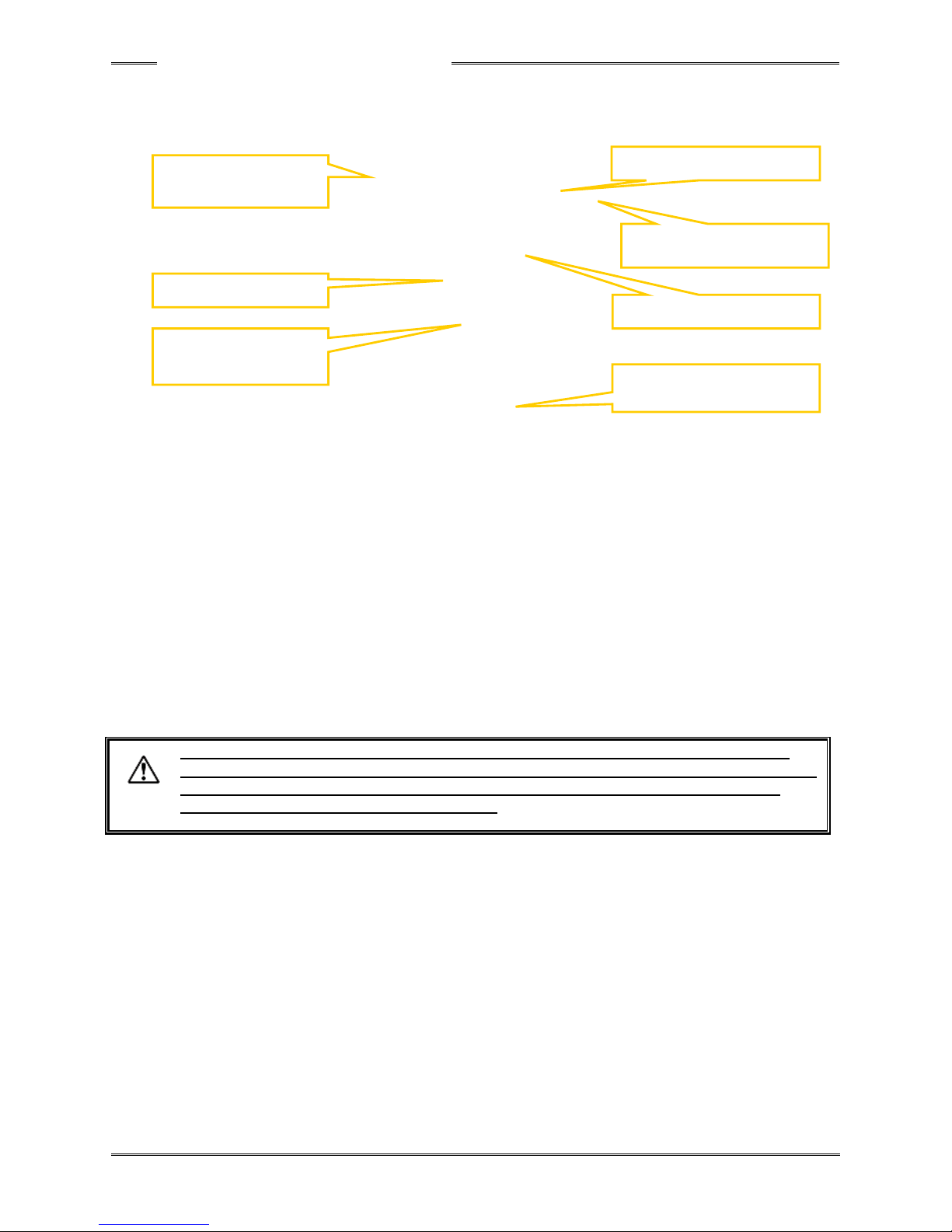
Chapter 6 Description of Operations
PAGE 6-4
(4) Tool
This is a pistol type hand-held type fastening tool provided with planetary gear, torque transducer,
servomotor, indicator LEDs, and operating switches etc.
①Starting switch: When the switch is turned ON (by pressing), the tool tip rotates for performing
fastening.
When started in a half-pressed state, the initial speed is maintained even during
free-running.
However, if the initial time is 0 (seconds), this function is cancelled.
When the switch is released during fastening (during rotation of the tip), the fastening
(rotation) is stopped.
However, if the switch is released before switching to the 2nd speed, judgment is not
performed and therefore fastening results will not be generated.
For ordinary fastening operation, continue to grip this switch until fastening is
completed.
②Reversing switch: This switch is for switching between normal and reverse rotation operations.
When the reverse rotation mode is set, the orange judgment LED flashes rapidly.
When the starting switch is turned ON in this state, the reverse rotation operation is
performed.
When the starting switch is released during the reverse rotation operation, the
operation is stopped.
* The torque limit is caused when you loose the bolt already fastened over 5N・m of
default setting in the case of the reverse operation and it automatically stops for safety.
This can be changed in the setting of fastening parameter. See the PAGE6-33,6-62.
If changed, be careful of big torque caused.
③LED for judgment and status indications (4 LEDs):
During the fastening operation, all judgment LEDs are OFF.
If the fastening result is OK, the green judgment LED lights up.
(In the case of TOTAL OK, the green judgment LED flashes slowly.)
If the fastening result is NG (failure), the red judgment LED becomes lit (angle-related
NG: rapid flashing; torque-related NG: continuously lit up; other NG: slow flashing).
During initialization upon power activation, the orange judgment LED lights up.
If as a result of initialization, the tool does not recognize the controller (communication
disconnected), rapid flashing in red is performed.
④CAL Check: This flashes only while the CAL button on the operation panel is being pressed.
If the result of CAL check is OK: The LED flashes rapidly in orange <--> green.
If the result of CAL check is NG: The LED flashes rapidly in orange <--> red.
Besides the above, all LEDs are OFF if an error occurs.
* The orange color is made to appear by the green LED and the red LED lighting up simultaneously
(when viewed at a close distance, the red and green colors appear separately).
①Starting switch
Torque transducer
and planetary gear
High-speed servomotor
Tool cable connector (lower
surface)
②Reversing switch
③LEDs for judgment and
status indications
Built-in preamplifier CPU
Built-in gyrosensor
Caution
Page 65
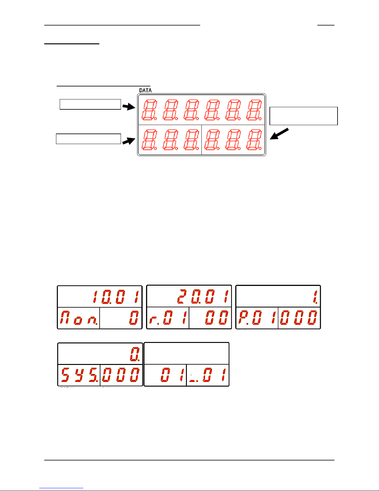
Chapter 6 Description of Operations
PAGE 6-5
6-2 RUN Mode
When the power is activated (turned ON) and the initial process ends, the operation enabled mode
(RUN mode) is entered. In the RUN mode, mainly the fastening results, abnormality status, Axis No.,
parameters, etc., are indicated.
Data Indication Part (RUN Mode)
DATA Indication Part
In the real time mode, fastening result mode, and parameter (system) setting mode, the fastening
result, set value (parameter), or executed value is indicated here as designated by the
COUNT/D-No. indication part.
WORK Indication Part
The WORK No. is indicated here (if sequence operation is disabled, the parameter No. is
indicated). When an error occurs, the abnormal state No. is indicated in the operation view.
COUNT/D-No. Indication Part
In the real time mode, fastening result mode, and parameter (system) setting mode, the No. of the
data indicated in the DATA indication part is indicated.
Also in the operation view, the current speed state is indicated during the fastening operation and
the current cycle count value (C##) is indicated when the fastening operation is not started. The
abnormal state No. sub code is indicated when an error occurs.
■Real Time Mode ■Fastening Result Mode ■Parameter Setting Mode
■System Setting Mode ■Operation View
Please refer to the following pages concerning the respective modes in the RUN mode.
DATA Indication Part
WORK Indication Part
COUNT/D-No. Indication
part
WORK
COUNT/D-NO
c
P
Page 66
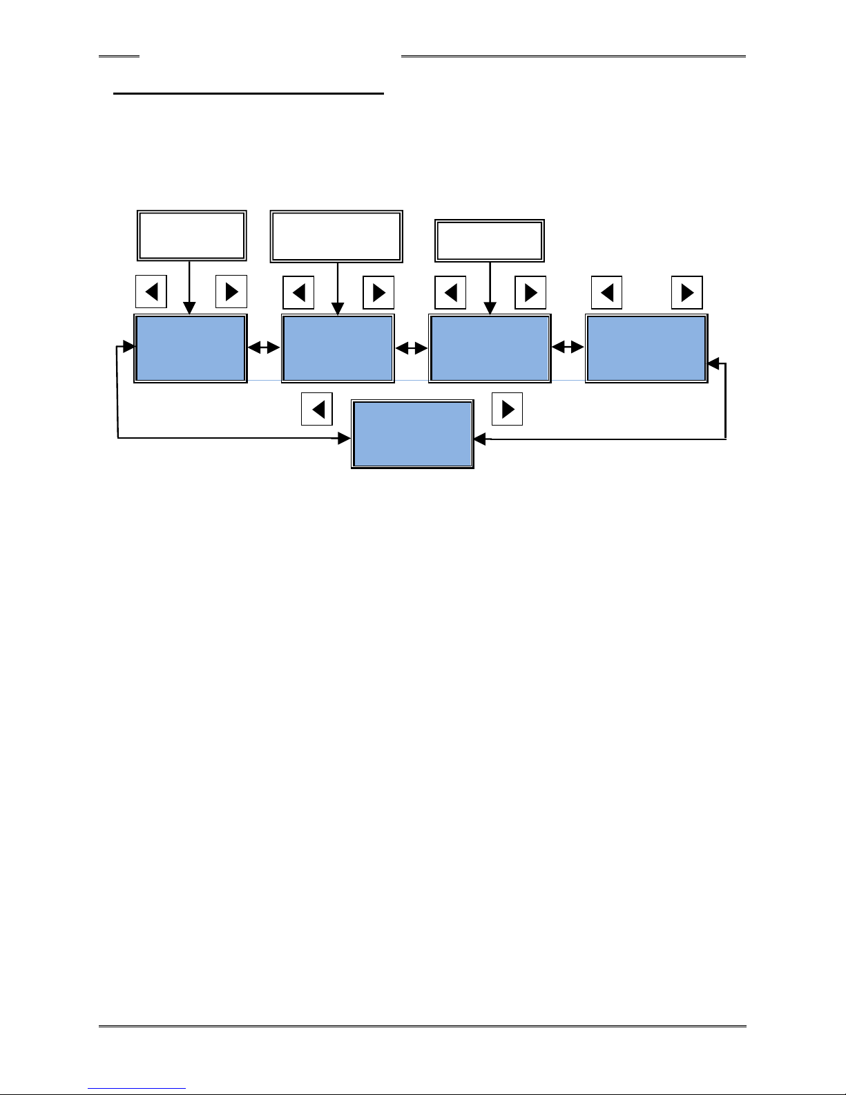
Chapter 6 Description of Operations
PAGE 6-6
6-2-1 Changing Modes in the RUN Mode
In the RUN mode, selection among the five modes can be performed by pressing the [◄] or [►]
switch. Further, in modes other than “Operation View,” the indicated content can be changed by
pressing the [▲] or [▼] switch.
Also when fastening starts, the mode changes automatically to “Operation View” and at the end of
fastening, the mode changes to the “Fastening Result Mode.” However, changing of indication and
changing of the mode by the switches cannot be performed during the fastening operation.
Real Time Mode
Operation View
(Change of
Work)
Fastening Result
Mode
(COUNT Indication)
Parameter Setting
Mode
System Setting
Mode
●Real Time Mode
The currently executed values are indicated in this mode.
The indicated content is changed with the [▲] or [▼] switch. This mode is indicated immediately
after the activation of the control power.
●Operation View
The current state of the controller and the speed state during the fastening operation are
indicated in this mode.
The indication changes to the indication during the fastening operation from the start of fastening
to the end of fastening.
The operation view is indicated when the state of the controller is changed, such as when an
errror occurs, the STOP signal is input in the “OFF” state, the BYPASS signal is input in the “ON”
state, etc.
The selected WORK No. is changed with the [▲] or [▼] switch.
However, this function is disabled when work selection by an external I/O is enabled.
●Fastening Result Mode
The fastening results are indicated in this mode.
The fastening result content is changed with the [▲] or [▼] switch.
However, when the fastening result D-No. is [00 (PEAK TORQUE)], the COUNT value [c##] is
indicated.
The result is indicated automatically after the end of fastening.
●Parameter Setting Mode
The fastening parameters are indicated in this mode.
The indicated set value is changed with the [▲] or [▼] switch.
●System Setting Mode
The system parameters are indicated in this mode.
The indicated set value is changed with the [▲] or [▼] switch.
After activation
of control power
Occurrence of error
or start of fastening
operation
After end of
fastening
Page 67
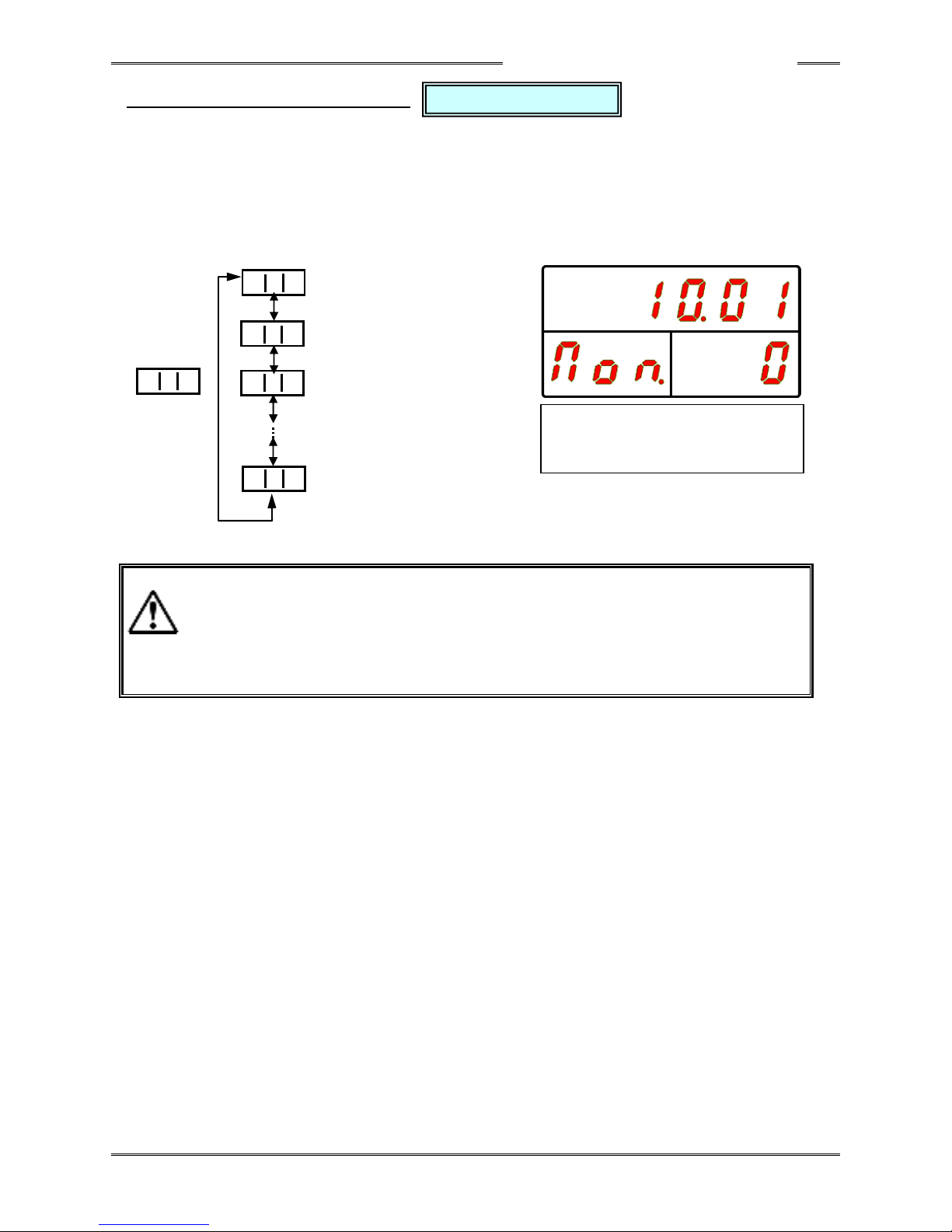
Chapter 6 Description of Operations
PAGE 6-7
6-2-2 Indications in the RUN Mode
In the real time mode, [Mon.] is indicated on the WORK Indication Part.
The value in the COUNT/D-No. indication part is incremented or decremented with the [▲] or [▼]
switch to change the indicated content.
Also, the value in the COUNT/D-No. indication part can be skipped by 5 at a time by long-pressing the
[▲] or [▼] switch.
“WORK” “COUNT/D-NO” “DATA”
Torque Value Indication
Torque Voltage Value Indication
Maximum Torque Value Indication
Fieldbus
status monitor
Please refer to the “List of Contents Indicated in the Real Time Mode” regarding the respective data
contents indicated at the DATA indication part when “COUNT/D-No.” is changed.
・When the CAL switch or the RESET signal is input in the ”ON” state when any of
D-Nos. 3 ~ 7 is indicated, the torque will not be indicated at the upper stage of the
indicator (the check itself will be executed).
・When the CAL switch or the RESET signal is input in the ”ON” state in the real time
mode, “CAL” or “RES” will not be indicated in the D-No. indication part.
Real time Mode
~
[▲] switch or [▼] switch
(skipping by 5 at a time by
long-pressing)
0
1 9 2 1
M o n
Caution
Page 68
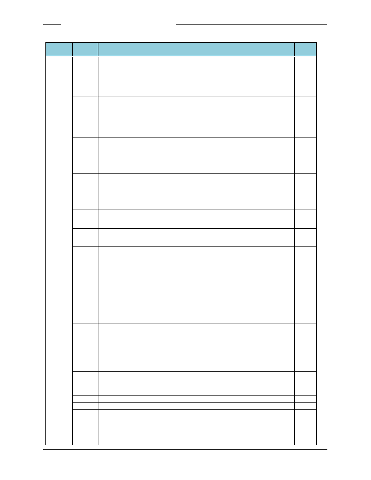
Chapter 6 Description of Operations
PAGE 6-8
●List of Contents Indicated in the Real Time Mode
WORK
COUNT/
D-NO
DATA
contro
llers
Mon.
0
[Torque Value Indication]
The load that is currently applied to the torque transducer is indicated in real time.
When the [CAL] switch is pressed, the torque value converted in terms of the
calibration torque is output.
Nm
1
[Torque Voltage Value Indication]
The torque signal voltage that is currently applied to the torque transducer is
indicated in real time. When the [CAL] switch is pressed, the torque voltage is
output in terms of a potential difference of approximately Δ3.75V.
V
2
[Maximum Torque Value Indication] (Maximum Torque Value Hold)
The peak torque from the point at which the [RESET] switch was pressed last in
the real time mode is indicated. Servo lock is performed for 1 minute when the
[SET] switch is pressed.
Nm
3
[Rotating Angle Indication]
The angle of rotation from the current position is indicated in real time. When the
RESET signal is set to “ON” or when the fastening operation is started by the OFF
→ ON raising of the START signal, the angle value becomes 0.
deg
4
[Load Rate]
The current motor load rate is indicated in real time. When 100 is exceeded,
Abn. 08-10 “Overload Error” is generated.
%
5
[Current Value]
The present current value is indicated in real time.
A
6
[Simplified I/O Monitor]
When SW2: Pin No. 6 at the bottom surface of the controller is ON, the indication
will be as shown in the diagram below (IO-OFF) (external input/output disabling
function).
Ordinarily, the 12 bits of the standard DIO are monitored and indicated as shown
in the diagram below.
When the SET button is long-pressed, forced ON output is performed (at 0.5
second intervals) the order of the standard DO (bit 0 ... bit 11 from the left).
When [↑], [↓], [→], [←], or [SET] is pressed in the middle of the forced output, the
forced output is ended.
During the forced output, the fastening operation is blocked.
Standard DI monitoring can be performed even during the forced output.
7
[ZERO/CAL Voltage Error Warning]
If the CAL voltage or ZERO voltage, measured when the control power is
activated, when the self-checking is performed at the start of fastening, when the
CAL switch of the indicator is pressed, or when the RESET signal is turned “ON,”
is of an error warning value, the indication (V Warn) shown in the drawing below
will be indicated. When the RESET signal is turned “ON” after the warning
indication, the [------] is re-indicated.
8
[Tool Rotation Speed Monitor] (+: CW/-: CCW)
During stoppage: The maximum rotation speed of the connected tool is indicated.
During rotation: The connected tool rotation speed converted from the motor
feedback speed is indicated.
Rpm
9
[Tool Response•St1.] (0~255)
Digit
10
[Tool Response•St2.] (0~15)
Digit
11
[Tool Response•Ad1.] (0~255)
The actual level value of the starting trigger switch is indicated.
Digit
12
[Tool Response•Ad2.] (0~255)
The actual level value of the F/R slide switch is indicated.
Digit
Page 69
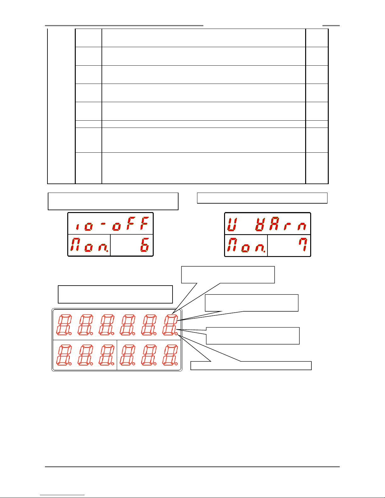
Chapter 6 Description of Operations
PAGE 6-9
13
[Tool Response•G. Gyrosensor Shake Detection Angle]
-2048° ~ +2047°
Deg
14
[Tool Command•Ct1.] (0~255)
CAL ON, GYRO RESET, etc.
Digit
15
[Tool Command•Ct2.] (0~255)
Angle conversion constant (fixed at 67)
Digit
16
[Tool Command•LEd.] (0~255)
LED-related command
Digit
17
[Tool Command•BuZ.] (0~255)
Buzzer-related command
Digit
18
[Tool Command•Gan. Gyro Restriction Angle] (0~255)
Deg
19
[Fieldbus•Status Monitor•FbS]
Fieldbus connection condition: In the normal state, “4” is indicated.
Any other indication indicates an unconnected state (the STOP mode is entered
and operation is disabled).
20
[Angle Head Torque Variation [%]]
Displays the current torque variation rate of the angle head after the fastening
operation.
When the rate exceeds the value set in D-No.541“[Angle Head Torque Variation]”,
A.09-10 “Angle Head Torque Variation Abnormal” occurs.
%
D-No. 006: External I/O Disabling Function
(SW2: Pin No. 6 is ON)
D-No. 7: ZERO/CAL Voltage Error Warning
D-No. 006: Simplified I/O Monitor
(SW2: Pin No. 6 is OFF)
Lit up during forced output (all digits).
Standard DI (lit up if ON)
bit0 ... bit11
Standard DO (lit up if ON)
bit0 ... bit11
AUX. DI (lit up if ON)
Batch reset input signal
Page 70
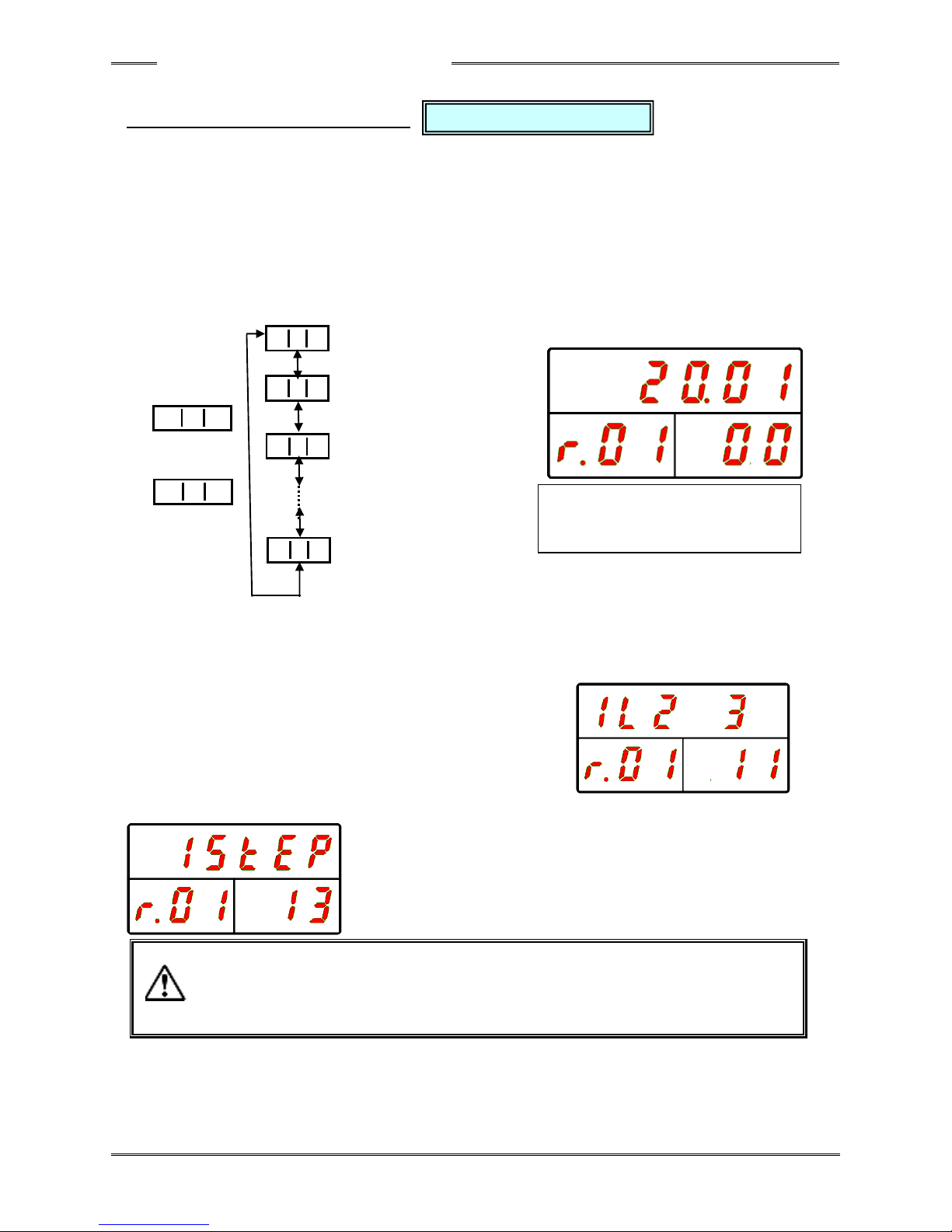
Chapter 6 Description of Operations
PAGE 6-10
6-2-3 Indications in the RUN Mode
In the fastening result mode, “r” is indicated at the 100s digit of the WORK indication part and the
parameter No. (01 ~ 64) of the fastening operation that was performed is indicated by the 10s and 1s
digits.
The value in the COUNT/D-No. indication part is incremented or decremented with the [▲] or [▼]
switch to change the indicated content.
* If fastening has not been started, “r00” is indicated.
Also, the value in the COUNT/D-No. indication part can be skipped by 5 at a time by long-pressing the
[▲] or [▼] switch.
“WORK” “COUNT/D-NO” “DATA”
Peak Torque
Final Angle
Rate 1
ACCEPT count
Please refer to the “List of Contents Indicated in the Real Time Mode” on the next page regarding the
respective data contents indicated at the DATA indication part when “COUNT/D-No.” is changed.
■Rate 1 ■1st NG Item ■Rate 1/2/3 Judgment
■Number of Fastening Steps ■Fastening Method (Torque Method) ■Reverse Flag
・The indicated content of the following D-Nos. are not stored in the fastening result
record of the controller.
D-No. 12 “Fastening Method,” D-No. 13 “Number of Fastening Steps,”
D-No. 14 “Self-Checking Flag,” D-No. 15 “Reverse Flag,” and
D-No. 15 “Servo Lock Flag.”
Fastening Result Mode
~
3 6
0 2
0 1
0 0
r 0 1
~
r 6 4
c
[▲] switch or [▼] switch
(skipping by 5 at a time by
long-pressing)
Caution
Page 71
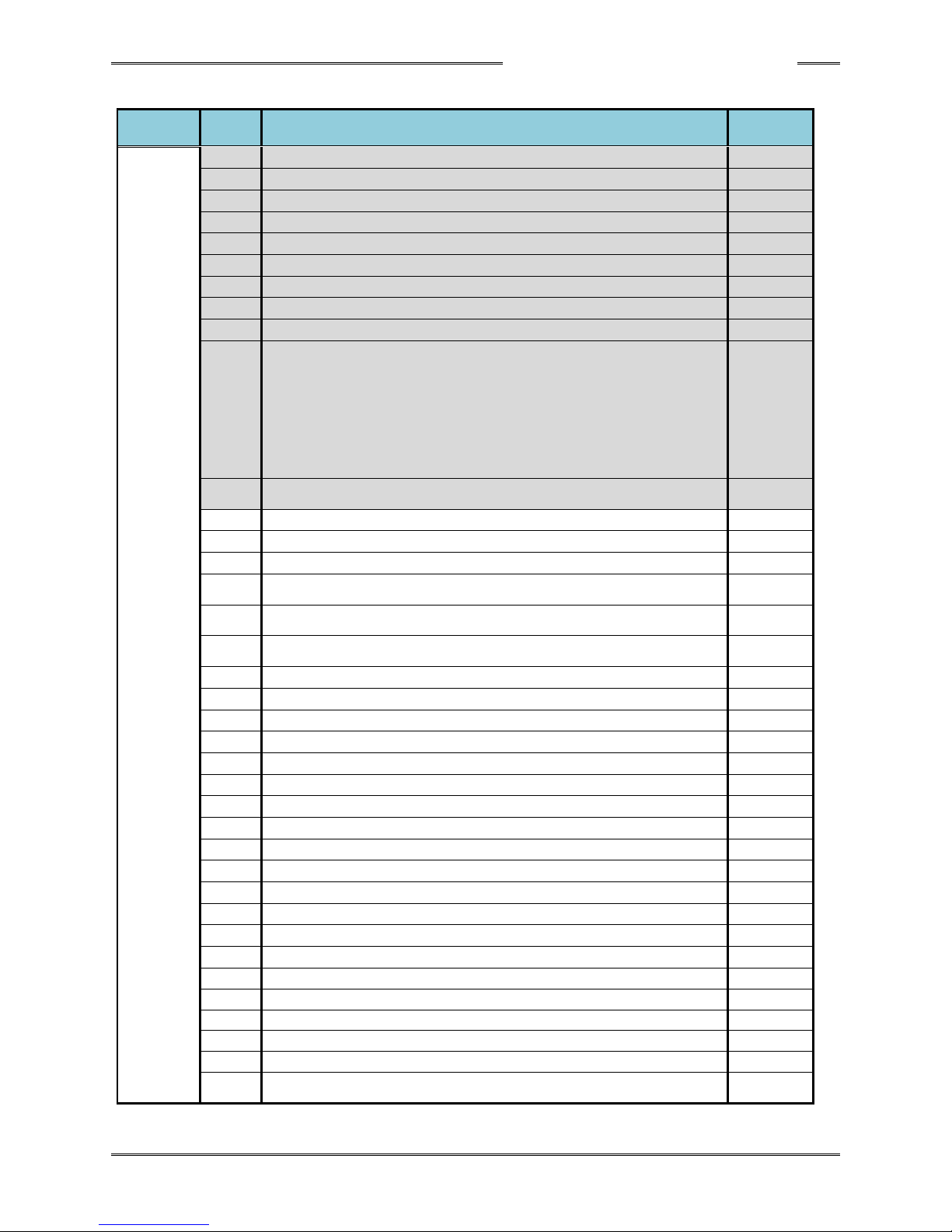
Chapter 6 Description of Operations
PAGE 6-11
●List of Contents Indicated in the Fastening Result Mode
WORK
COUNT
/D-NO
DATA
controller
r01~r64
c##
Peak torque H/L
N•m
01
Final angle H/L
Deg
02
Rate 1 H/L
N•m/deg
03
Rate 2 H/L
N•m/deg
04
Rate 3 H/L
N•m/deg
05
1st timeH/L
Sec
06
2nd time H/L
Sec
07
Cycle time
Sec
08
Differential angle H/L
Deg
09
Axis judgment
reject: REJECT (fastening NG (fail))
accept: ACCEPT (fastening OK)
abn: Stoppage due to ABNORMAL (error occurrence) signal
stop: Stoppage due to STOP (emergency stop) signal
reset: System cleared by RESET signal
bypass: Stopping due to BYPASS signal
st-off: START signal set to OFF during output of BUSY (operating) signal
10
1st NG item *The D-No. of the fastening NG (fail) item that occurred first is
indicated.
11
Rate 1/2/3 judgment H/L
12
Fastening method … trq: torque method, ang: angle method
13
Number of fastening steps … 1 step, 2 steps, 3 steps
14
Self-checking flag (SC) … ON: self-checking performed
OFF: self-checking not performed
15
Reverse flag (RV) … ON: reverse rotation performed
OFF: reverse rotation not performed
16
Servo lock flag (SL) … ON: servo lock performed
OFF: servo lock not performed
17
1st peak torque
N•m
18
2nd peak torque
N•m
19
Snug torque H
N•m
20
Final torque H/L
N•m
21
Rate 1 increment torque (torque from start of rate 1 to end of rate 1)
N•m
22
Rate 1 increment angle (angle from start of rate 1 to end of rate 1)
Deg
23
Rate 2 increment torque (torque from start of rate 2 to end of rate 2)
N•m
24
Rate 2 increment angle (angle from start of rate 2 to end of rate 2)
Deg
25
Rate 3 increment torque (torque from start of rate 3 to end of rate 3)
N•m
26
Rate 3 increment angle (angle from start of rate 3 to end of rate 3)
Deg
27
Peak current H/L (current high/low limit warning indication)
N•m
28
Rundown revolutions H/L
rev.
29
Load rate
%
30
Current value at stopping of fastening
A
31
------ indication
32
Axis cycle count (×1 million) * “--" if less than 1 million cycles
33
Axis cycle count (×1)
34
Tool cycle count (×1 million) * “--" if less than 1 million cycles
35
Tool cycle count (×1)
36
ACCEPT COUNT *0 to cycle count (0 to 99)
This DATA indication is always performed as [c##] for COUNT/D-No. 00.
NG (failure) result indication is performed for COUNT/D-No. 00 to 10.
Page 72
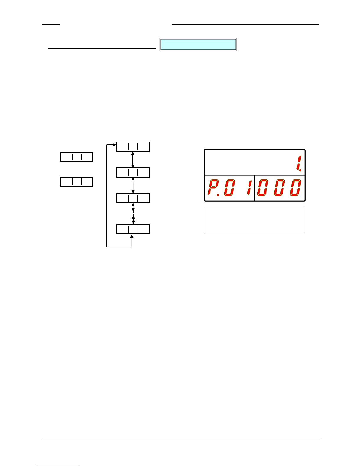
Chapter 6 Description of Operations
PAGE 6-12
6-2-4 Indications in the RUN Mode
In the parameter setting mode, “P” is indicated at the 100s digit of the WORK indication part and
the parameter No. (01 to 64) is indicated by the 10s and 1s digits. The D-No. indication part is
changed by pressing the [▲] or [▼] switch and the content of the data No. is indicated accordingly.
When the [▲] switch is pressed when the last data No. of parameter No. is indicated, the value
in the WORK indication part is incremented by 1.
Also, when the [▼] switch is pressed when the head data No. of each parameter No. is
indicated, the value in the WORK indication part is decremented by 1.
Also, the value in the D-No. indication part can be skipped by 10 at a time by long-pressing the
[▲] or [▼] switch.
Please refer to the “List of Parameters” regarding the details of the set values.
“WORK” “COUNT/D-No.” “DATA”
Fastening Method
Fastening Steps
Fastening Option
Sequence
Stage 8
[▲] switch or [▼] switch
(skipping by 10 at a time by
long-pressing)
Parameter Setting Mode
~
P 0 1
~
0 0 1
0 0 0
0 0 2
5 8 8
P 6 4
Page 73
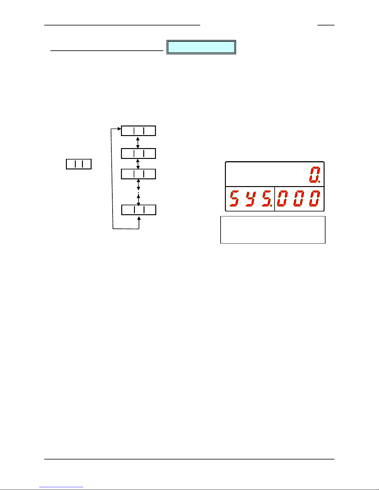
Chapter 6 Description of Operations
PAGE 6-13
6-2-5 Indications in the RUN Mode
In the system setting mode, “SYS.” is indicated in the WORK indication part.
The D-No. indication part is changed by pressing the [▲] or [▼] switch and the content corresponding
to No. is indicated accordingly. The value in the D-No. indication part can be skipped by 10 at a time
by long-pressing the [▲] or [▼] switch.
Please refer to the “List of Parameters” regarding the details of the set values.
“WORK” “COUNT/D-No.” “DATA”
Torque controller
Software Version
Amplifier Version
Touch panel
Port Number
System Setting Mode
~
0 0 1
0 0 0
0 0 2
5 0 3
S Y S
[▲] switch or [▼] switch
(skipping by 10 at a time by
long-pressing)
Page 74
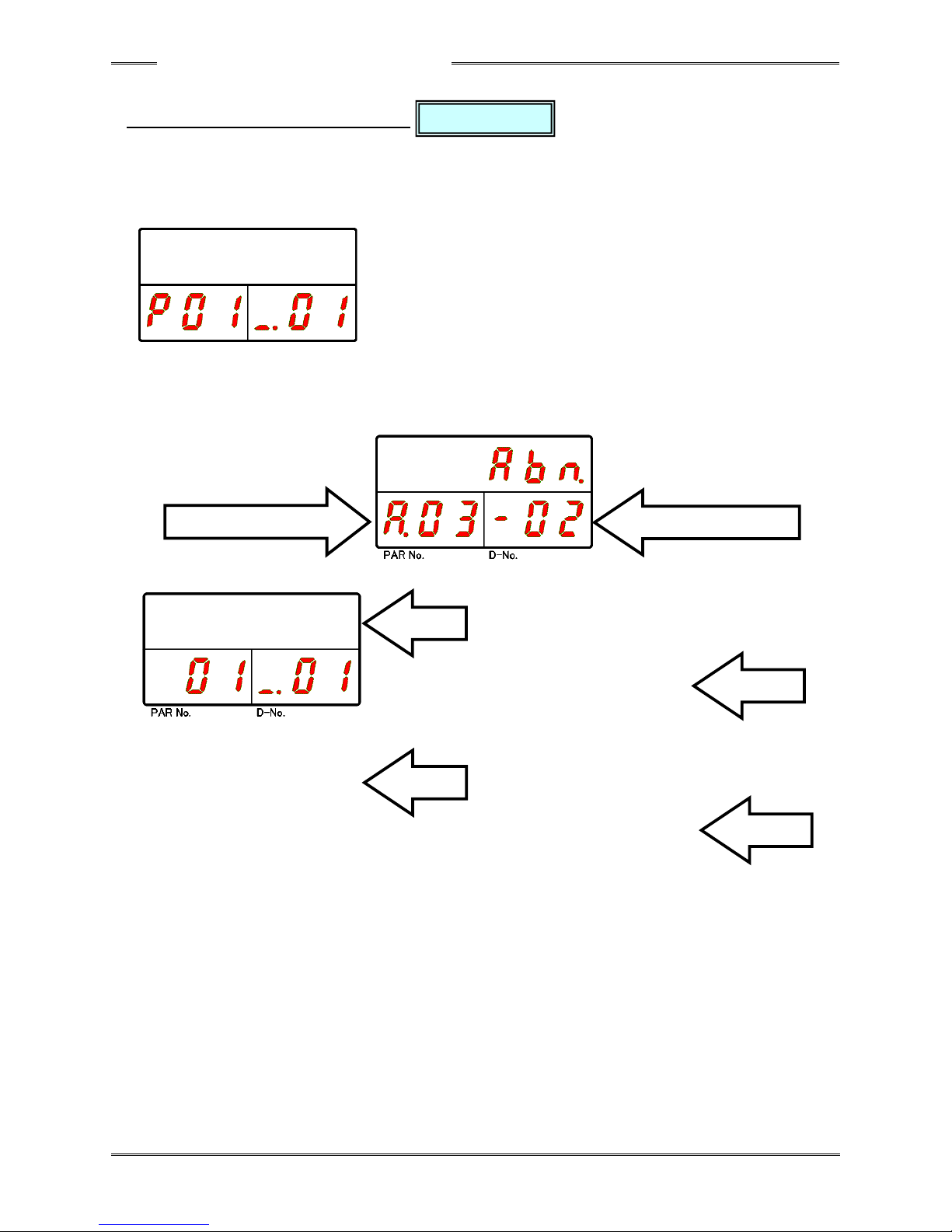
Chapter 6 Description of Operations
PAGE 6-14
6-2-6 Indications in the RUN Mode
In the operation view, the currently selected work (parameter) No. (01 ~ 64) is indicated in the
WORK indication part. The Axis No. of the controller is indicated by the 10s and 1s digits of the
COUNT/D-No. indication part.
■Ordinary View
When the state of the system is changed due to occurrence of an error or setting of the STOP signal
to “OFF,” etc., transition to the status indication is performed automatically and the contents
indicated in the respective indication parts change accordingly.
■When an error occurs (ABNORMAL signal “ON”)
■When the BYPASS signal is turned “ON” ■When the RESET switch is turned “ON”
■When the STOP signal is turned “OFF” ■When the CAL switch is turned “ON”
Operation View
P
P
P
P
P
ro
G
Abnormal state signal
Sub code indication
“bypass”
“stop”
“cal”
“Res”
Page 75
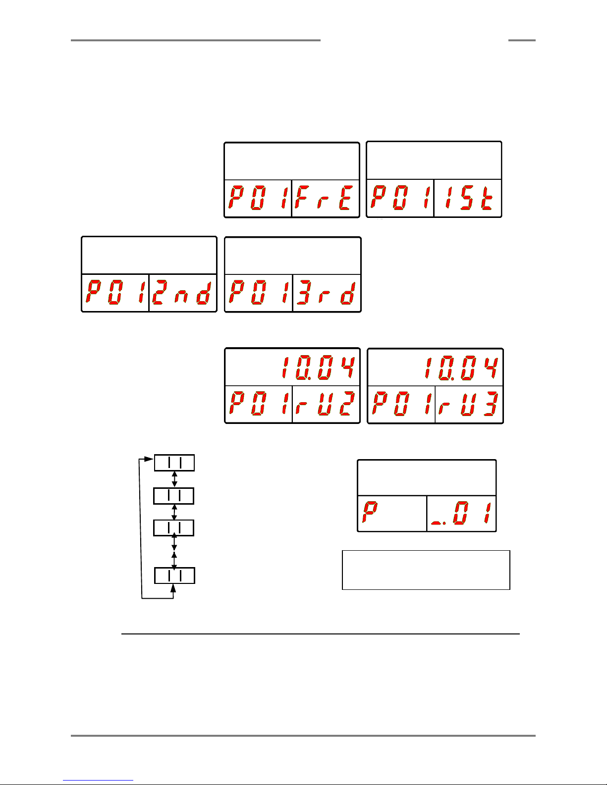
Chapter 6 Description of Operations
PAGE 6-15
Also, during the fastening operation, the operation speed and the fastening step state are indicated.
In the indication during the fastening operation, the parameter No. (01~ 64) that is currently put in
operation is indicated in the WORK indication part. The mode cannot be changed in the indication
during the fastening operation.
Transition to the fastening result mode is performed automatically after the fastening ends.
The following are indication examples during a fastening operation of parameter No. 1.
■During initial speed operation ■During freerun speed operation ■During 1st speed operation
■During 2nd speed operation ■During 3rd speed operation
*The indication content of the upper stage of the indicator is maintained during reverse operation.
■During reverse 1 speed operation ■During reverse 2 speed operation ■During reverse 3 speed operation
“WORK”
Work No. 01
Work No. 02
Work No. 03
Work No. 64
*The operation cannot be performed if work selection by external I/O is set.
~
P 0 1
P 6 4
P 0 3
P 0 2
64
The “WORK” No. is changed with
the [▲] switch or the [▼] switch.
Page 76
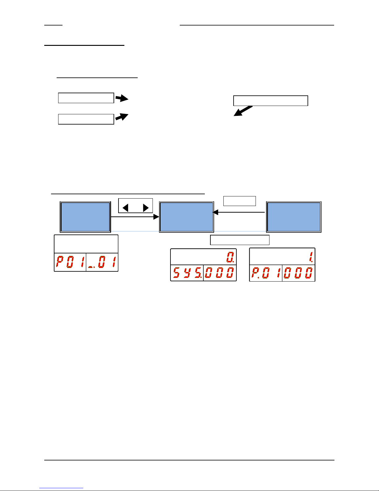
Chapter 6 Description of Operations
PAGE 6-16
6-3 PROGRAM Mode
The parameter settings can be changed in the PROGRAM mode.
The Data No. and parameter of each parameter No. are indicated on the indicator.
Indicator (PROGRAM Mode)
●DATA indication part
The set value (parameter) is indicated.
●WORK indication part
The fastening parameter No. is indicated.
●COUNT/D-No. indication part
The data No. indicated in the DATA indication part is indicated.
6-3-1 Changing Modes in the PROGRAM Mode
Operation View
Set Value
Selection Mode
Set Value Editing
Mode
●Operation View
The current state of the controller is indicated in this mode.
Indication in this mode is performed immediately after changing from the RUN mode to the
PROGRAM mode.
Changing to the set value selection mode is performed by the [◄] and [►] switches.
However, in the “Parameter Setting Mode” and the “System Setting Mode,” the mode is changed
directly to the set value selection mode.
●Set Value Selection Mode
A parameter is selected in this mode.
The [◄] and [►] switches are used to change the position of the cursor.
The [▲] and [▼] switches are used to change the indicated set value.
●Set Value Editing Mode
A parameter is set in this mode.
The set value is edited using the [▲] and [▼] switches and set with the “SET” switch.
When the “RESET” switch is pressed, the setting in the process of being changed is discarded and
returned to the setting before changing.
DATA indication part
WORK indication part
COUNT/D-No. indication part
or
SET or RESET
SET
ProG
Page 77
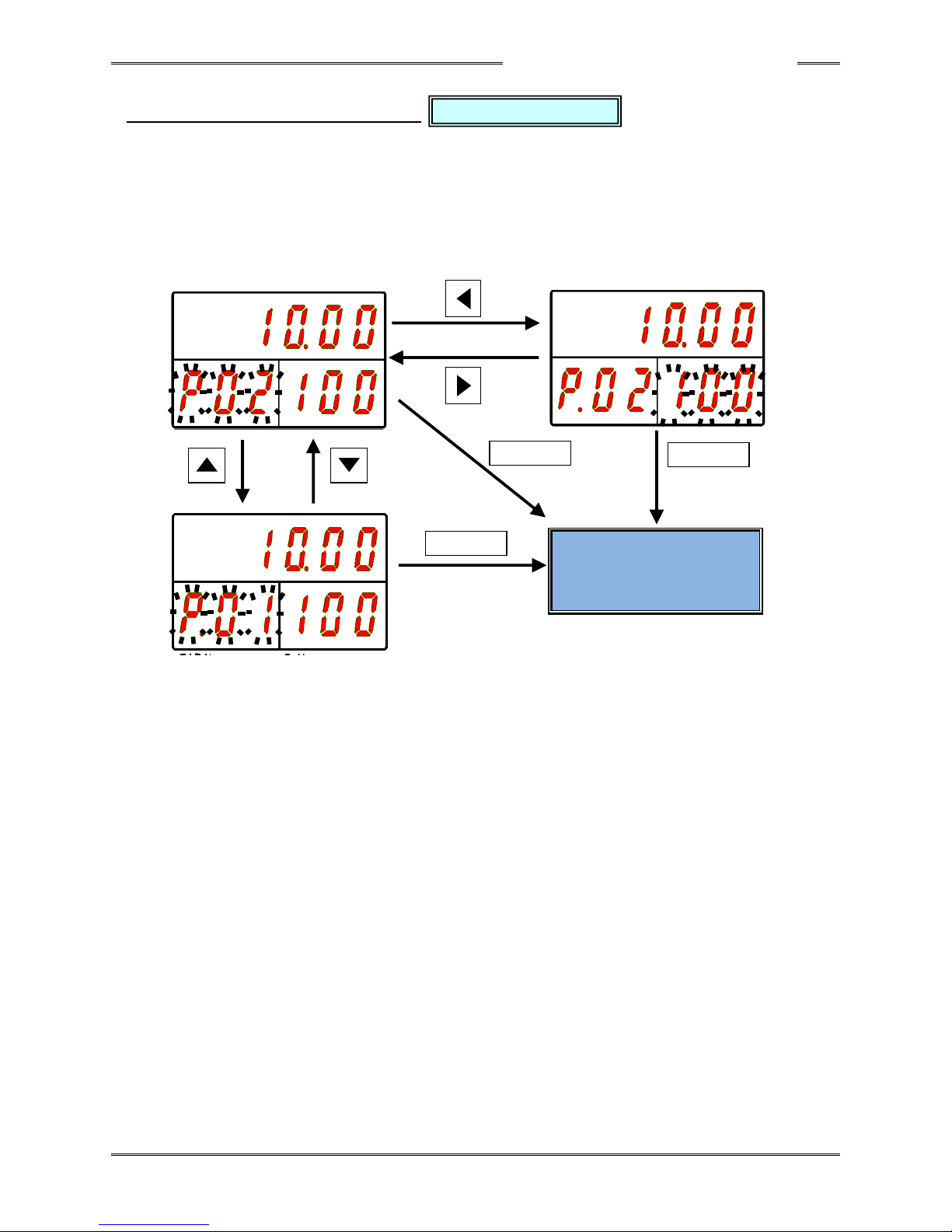
Chapter 6 Description of Operations
PAGE 6-17
6-3-2 Indications in the PROGRAM Mode
Immediately after changing to the “Set Value Selection Mode,” the cursor (flashing number) is
indicated in the WORK indication part when the [◄] switch is pressed and is indicated in the
COUNT/D-No. indication part when the [►] switch is pressed.
When the [▲] or [▼] switch is pressed, the numerical value at the cursor position changes by ±1.
When the [►] switch is pressed, the cursor position moves to the COUNT/D-No. indication part.
Also, when the [◄] switch is pressed, the cursor position moves to the WORK indication part.
When the “SET” switch is pressed, changing to the “Set Value Editing Mode” is performed.
Set Value Editing Mode
Set Value Selection Mode
SET
SET
SET
Page 78
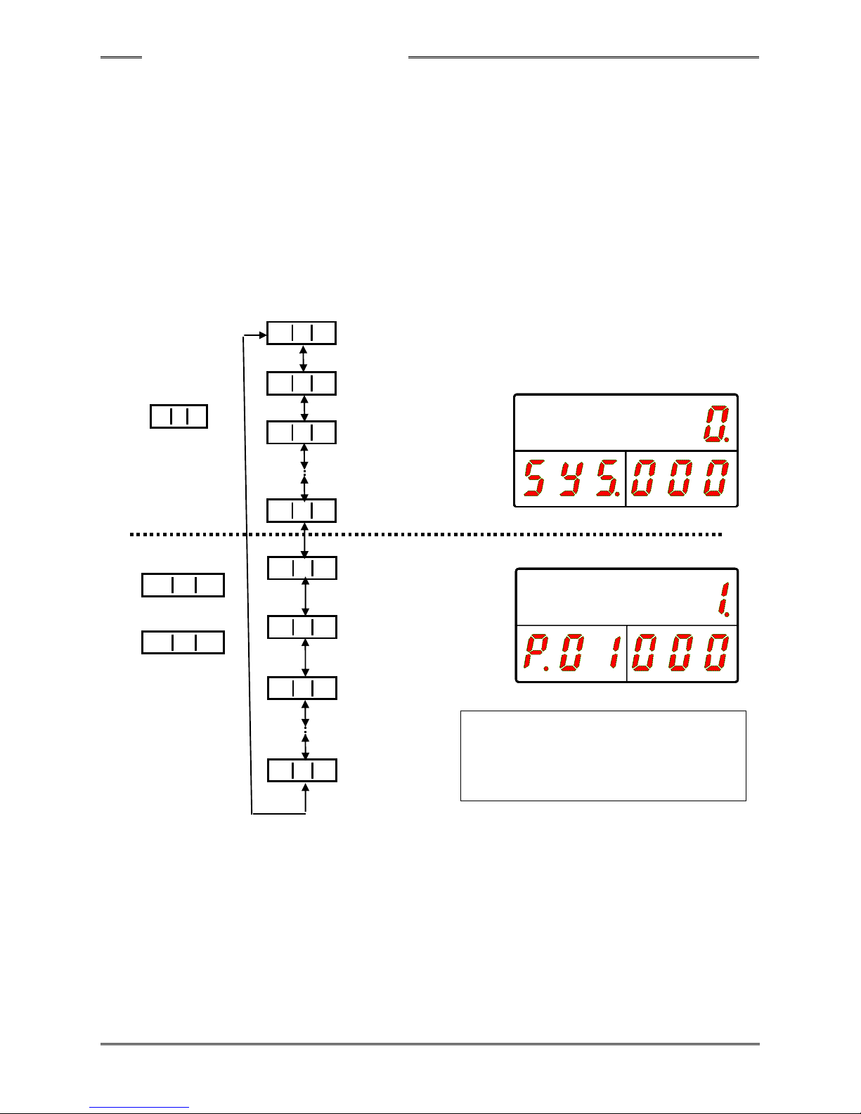
Chapter 6 Description of Operations
PAGE 6-18
In the set value selection mode, “SYS.” is indicated in the WORK indication part in the case of a
system parameter and the parameter No. (01 to 64) is indicated in the WORK indication part in the case
of a fastening parameter.
The WORK indication part is changed by pressing the [►] or [◄] switch and the content of the data No.
is indicated accordingly.
When the [▲] switch is pressed when the last data No. of each parameter No. is indicated, the value
in the WORK indication part is incremented by 1.
Also, when the [▼] switch is pressed when the head data No. of each parameter No. is indicated, the
value in the WORK indication part is decremented by 1.
Also, the current cursor position can be moved by pressing the [►] or [◄] switch and, by long-pressing
the [▲] or [▼] switch, the value in the WORK indication part can be skipped by 5 at a time or the value in
the WORK indication part can be skipped by 10 at a time.
Please refer to the “List of Parameters” regarding the details of the set values.
“WORK” “COUNT/D-No.” “DATA”
Torque controller
Software Version
Amplifier Version
ID input selection
Fastening Method
Fastening Steps
Fastening Option
Sequence
Stage 8
~
0 0 1
0 0 0
~
P 0 1
0 0 2
~
5 0 3
S Y S
0 0 1
0 0 0
0 0 2
5 8 8
P 6 4
[▲] switch or [▼] switch
WORK indication part: skipping by 5 at a time
by long-pressing
COUNT/D-No. indication part: skipping by 10
at a time by long-pressing
Page 79
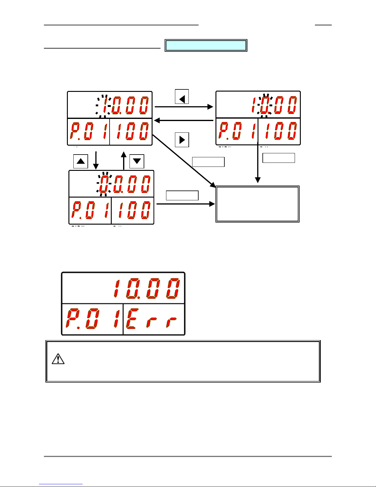
Chapter 6 Description of Operations
PAGE 6-19
6-3-3 Indications in the PROGRAM Mode
Immediately after changing to the “Set Value Editing Mode,” the cursor (flashing number) is indicated
in the upper stage of the indication part. When the [▲] or [▼] switch is pressed, the numerical value
at the cursor position changes by ±1.
When the [◄] or [►] switch is pressed, the digit of the cursor position changes by ±1.
When the set value is edited and the [SET] switch is pressed, the set value is changed and changing
to the set value selection mode is performed. When the [RESET] switch is pressed in the “Set Value
Editing Mode,” changing to the set value selection mode is performed without changing the set value.
Also, when the changed set value is outside the setting range, the following is indicated and changing
to the set value selection mode is performed without changing the set value.
• The changed parameter is effective when the PROGRAM mode switches to the RUN
mode, or when the PROGRAM signal changes from ON to OFF.
Turning the power OFF in the PROGRAM mode during the change returns to the
parameter before the change.
Set Value Editing Mode
Change of
Fastening
Parameter
SET
SET
SET
Caution
Page 80
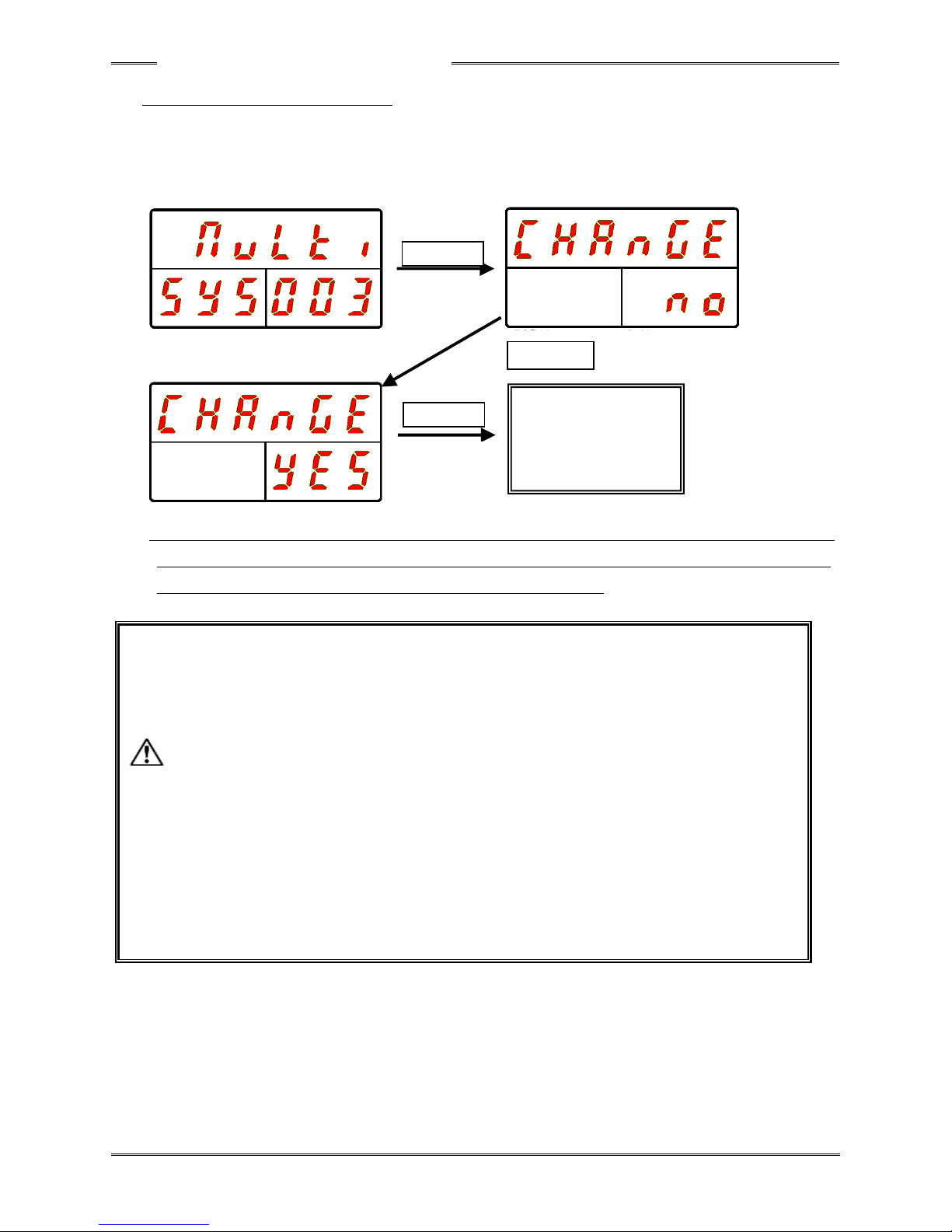
Chapter 6 Description of Operations
PAGE 6-20
●System Parameter Setting Method
A parameter with which [SYS] is indicated in the COUNT/D-No. indication part is a system
parameter and its set value is changed by editing the set value, then pressing the [SET] switch,
thereafter changing the indication of “NO” to “YES” with the [▲] or [▼] switch, and then pressing the
[SET] switch again.
*If after pressing the [SET] switch and then changing from “NO” to “YES,” 2 seconds elapses without
operating the [▲] or [▼] switch before the [SET] switch is pressed again, changing to the set value
selection mode is performed without the set value being changed.
•When changing from the PROGRAM mode to the RUN mode is performed or the
BYPASS signal is changed from ON to OFF, the changed parameter is stored in the
controller. When during a setting change, the power is turned OFF in the PROGRAM
mode, the setting of the parameter returns to that before the change.
•A portion of the system parameters are made available by reactivating the control
power after changing its setting (D-No. 003 System Indication, D-Nos. 011 ~ 016
TCP/IP Setting, etc.).
•When the controller setup tool No. (PAR No. “SYS,” D-No. “200”) is changed, the
fastening parameter set values are subject to initialization and automatic correction.
•Initialization…The calibration torque, the rate 1 ~ 3 high and low limits, the full scale
current, the high current limit, and the current limit are subject to initialization.
•Automatic Correction…If the torque, speed, or low current limit set value falls outside
the high or low limit value of the tool of the tool No. for which the set value was
changed, this set value is subject to automatic correction.
Change of
System
Parameter
▲ or ▼
SET
SET
Within 2 seconds
Within 2 seconds
Caution
Page 81
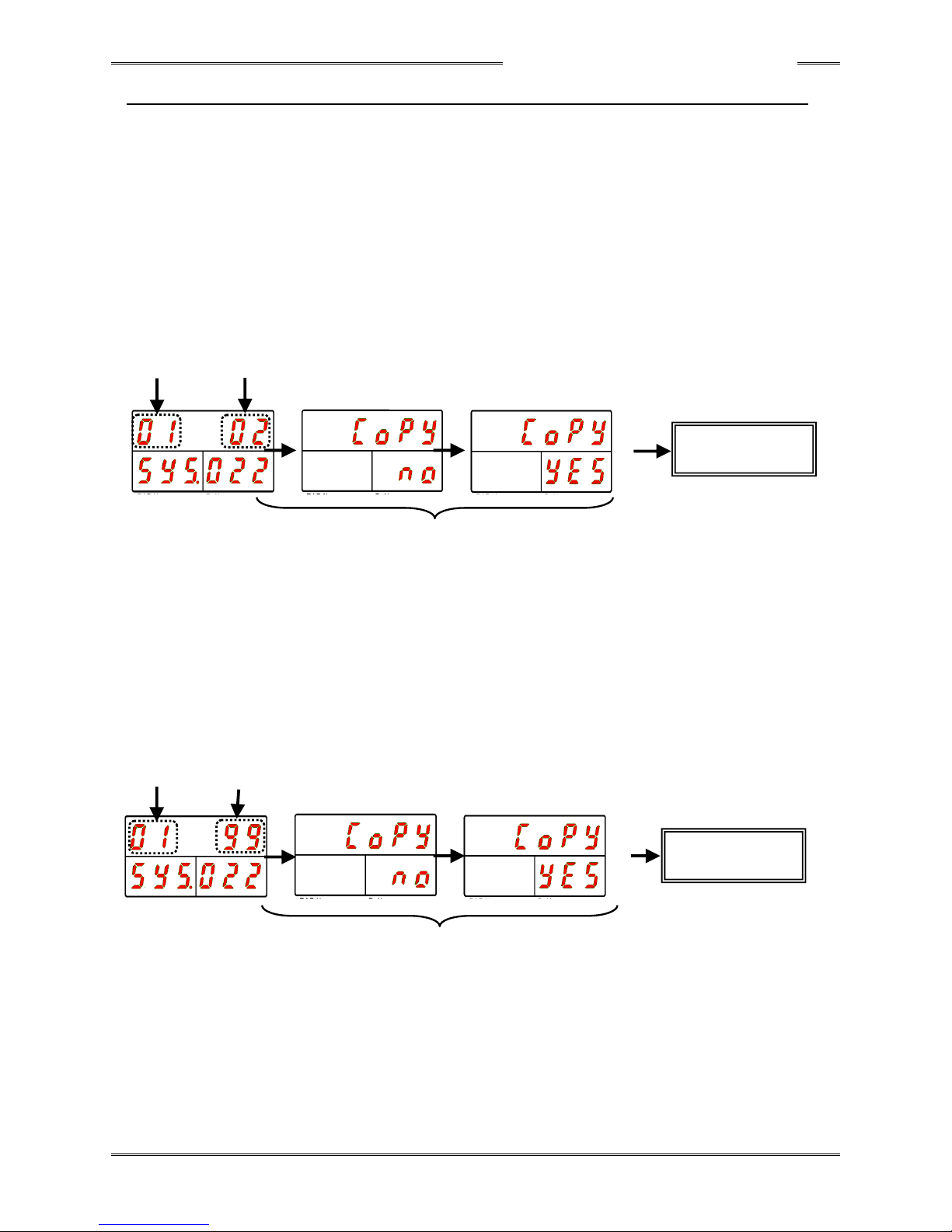
Chapter 6 Description of Operations
PAGE 6-21
6-4 Copying of Parameters/Erasure of the Fastening Result Record/Formatting of the CF Card
In setting the contents of multiple parameter Nos., a certain parameter No. can be copied to
another parameter No. in the set value editing mode. Parameters can be copied by the following
operation procedures.
●Procedures for Copying in Parameter controllers
1. When the controller is in the PROGRAM mode, make “CoPY,” with “SYS” indicated in the WORK
indication part and “022” indicated in the COUNT/D-No. indication part, be indicated and then press
“SET.”
2. Select the copy source parameter No. as the upper 2 digits of the DATA indication part.
3. Select the copy destination parameter No. as the lower 2 digits of the DATA indication part.
4. Press the SET switch and then press the [▲] or [▼] switch within 2 seconds.
5. After the indication at the DATA indication part changes to “CHANGE YES,” press the [SET] switch
within 2 seconds.
6. Copying in parameter units is executed.
●Batch Copying
Example: To copy the contents of parameter 1 into parameters 2 ~ 64
1. When the controller is in the PROGRAM mode, make “CoPY,” with “SYS” indicated in the WORK
indication part and “022” indicated in the COUNT/D-No. indication part, be indicated and then press
“SET.”
2. Select the copy source parameter No. as the upper 2 digits of the DATA indication part.
3. Select “99” as the lower 2 digits of the DATA indication part.
4. Press the SET switch and then press the [▲] or [▼] switch within 2 seconds.
5. After the indication at the DATA indication part changes to “CHANGE YES,” press the [SET] switch
within 2 seconds.
6. The parameter of the copy source is copied to all parameter in a batch.
Parameter
Unit Copy
Canceled if operation is not performed within 2 seconds.
Canceled if operation is not performed within 2 seconds.
Parameter
Batch Copy
[SET]
[▲] or [▼]
Copy Source
Copy Destination
[SET]
[SET]
[▲] or [▼]
Copy Source
“99”
[SET]
Page 82
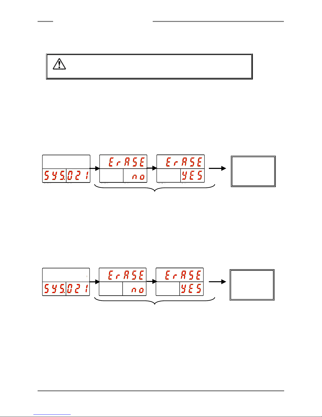
Chapter 6 Description of Operations
PAGE 6-22
Similar operations can be performed from “ErASE,” with “021” indicated in the D-No. indication part,
to erase all fastening result record stored in the controller.
・ Be careful in executing erasing operation because data cannot be
recovered after the fastening result record is erased.
●Fastening Result Record Erasing Operation Procedure
1. When the controller is in the PROGRAM mode, make “ErASE,” with “SYS” indicated in the WORK
indication part and “021” indicated in the COUNT/D-No. indication part, be indicated and then press
“SET.”
2. Press the [▲] or [▼] switch to select “SinGLE” and then press “SET.”
3. After the indication at the DATA indication part changes to “ErASE YES,” press the [SET] switch within
2 seconds.
4. When the erasing of the fastening result record is started, “ErASE” in the DATA indication part flashes
for a few seconds and the flashing stops when the erasure is completed.
●CF Card Formatting Operation
1. When the controller is in the PROGRAM mode, make “ErASE,” with “SYS” indicated in the WORK
indication part and “021” indicated in the COUNT/D-No. indication part, be indicated and then press
“SET.”
2. Press the [▲] or [▼] switch to select “CF” and then press “SET.”
3. After the indication at the DATA indication part changes to “ErASE YES,” press the [SET] switch within
2 seconds.
4. When the formatting of the CF card is started, “ForMAT” in the DATA indication part flashes for a few
seconds.
5. If formatting succeeds, “SuccES” is indicated in the DATA indication part for 3 seconds (CF ACCESS lights up in
green).
6. If formatting fails, “FAILEd” is indicated in the DATA indication part for 3 seconds (CF ACCESS lights up in red).
Formatting
of CF Card
Erasure of
Fastening
Result Record
Canceled if not operated for 2 seconds.
Canceled if not operated for 2 seconds.
SinGLE
CF
Caution
[SET]
[▲] or [▼]
[SET]
[SET]
[▲] or [▼]
[SET]
Page 83

Chapter 6 Description of Operations
PAGE 6-23
6-5 Fastening NG (Failure) Result Indications
When a fastening NG occurs, in addition to the NG lamp indication at the upper part of the controller, the item
detected as the fastening NG is indicated in the numerical value indication part by the present function.
In the case of fastening to the standard torque, judgments are made in the order: rate high/low limits,
differential angle high/low limits, 2ND region fastening high/low limit times, angle high/low limits, peak torque
high/low limits, and final torque high/low limits, and the item with which NG is detected first is indicated.
This function is planned to be incorporated as standard. It is planned that the NG result indication operation
is performed at all times.
Even if the reset, bypass, reverse, or CAL operation is performed, the indication is not canceled (as long as the
First-NG result No. exists). When fastening is started, the result is initialized and, in linkage, the alternating
indication ends.
Example of fastening
indication in case of
OK judgment
The fastening peak torque value is
indicated.
Example of high limit peak
torque NG judgment
Fastening result indication
The indication
changes every 1
second.
Fastening NG item indication
The judgment, “H,” is indicated first and then the
item is indicated.
NG content symbol
Judgment result
Fastening result
indication mode No.
Parameter No.
“r” at the head indicates the
result indication mode.
NG content symbols
・Ptrq Peak torque ・Ftrq Final torque
・Strq Snug torque ・StC Starting torque inhibit
・AnGL Final angle ・dIFF Differetntial angle
・1Str Rate 1 ・2ndr Rate 2
・3rdr Rate 3
・1Stt 1st time ・2ndt 2nd time
・turn Rundown revolutions
・St-off Lever Off ・Gyro Gyro Stop
If the fastening result indication item is the peak torque indication and the fastening NG item is the
angle high limit NG, the indication will be as follows.
Fastening result indication
Example of
low limit peak
torque NG
judgment
The indication
changes every 1
second.
Fastening NG item indication
The judgment, “H,” is indicated first
and then the item is indicated.
Page 84

Chapter 6 Description of Operations
PAGE 6-24
6-5-1 Example of Fastening NG item indication
1. Torque High Limit Judgment
High limit peak torque NG
Cause: Seizing or locking of the screw
Torque inhibit limit NG
Cause: Work fault, socket fault
2. Angle High Limit Judgment
High limit angle NG
Cause: Elongation of screw.
During final fastening, fastening was performed while the tool was
shaking greatly.
Screw tapping fault.
3. Rate High/Low Limit Judgment
Low limit Rate1 NG
Cause: Screw thread fault, tapping fault
High limit Rate1 NG
Cause: Redundant fastening
Bottom hitting of bolt
Low limit Rate2 NG
Cause: Abnormality of object of fastening.
High limit Rate2 NG
Cause: Redundant fastening
Error of object of fastening
Low limit Rate3 NG
Cause: Elongation of bolt
Error of object of fastening
High limit Rate3 NG
Cause: Redundant fastening
Seizing of bolt
Page 85

Chapter 6 Description of Operations
PAGE 6-25
4. Fastening Time High Limit Judgment
High limit 1ST time NG
Cause: Tapping fault of object of fastening, bolt thread fault
Detachment of socket
High limit 2ND time NG
Cause: Elongation of bolt
Cutting of bolt
Detachment of socket
5. Rundown Revolutions High Limit Judgment
Rundown Revolutions High Limit NG
Cause: Bolt fault
Detachment of socket
6. Others
Start Lever Off NG
Cause: Release the start lever
Gyro Stop NG
Cause: Gyro swing detection worked safety stop
Page 86

Chapter 6 Description of Operations
PAGE 6-26
6-5-2. NG Judgment
Judgments by the high and low limit values of torque, angle, time, and rundown revolutions are
performed during the fastening operation or after the end of fastening. The REJECT axis judgment is
made if a fastening result falls outside the high or low limit range.
* High and Low Limit Standard Values for Output Judgment
The high and low limit values of the HFC3000 System are as follows.
・High limit standard value (REJECT): A value exceeding the high limit standard value
・High limit standard value (ACCEPT): A value that is no more than the high limit standard value
・Low limit standard value (REJECT): A value less than the low limit standard value
・Low limit standard value (ACCEPT): A value that is no less than the high limit standard value
REJECT < Low Limit Standard Value ≤ ACCEPT ≤ High Limit Standard Value < REJECT
Be careful as the output judgment is not performed regardless of the high and low
limit set values when the settings of the fastening parameters D-No. 003 “Judge
Item 1” and D-No. 004 “Judge Item 2” are 0.
205: Torque Inhibit Angle
200: Final Angle Low Limit
201: Final Angle High Limit
111: Torque Inhibit Limit
107: Snug Torque
108: Snug Torque High Limit
118: Final Torque Low Limit
119: Final Torque High Limit
101: Peak Torque Low Limit
102: Peak Torque High Limit
Caution
Page 87
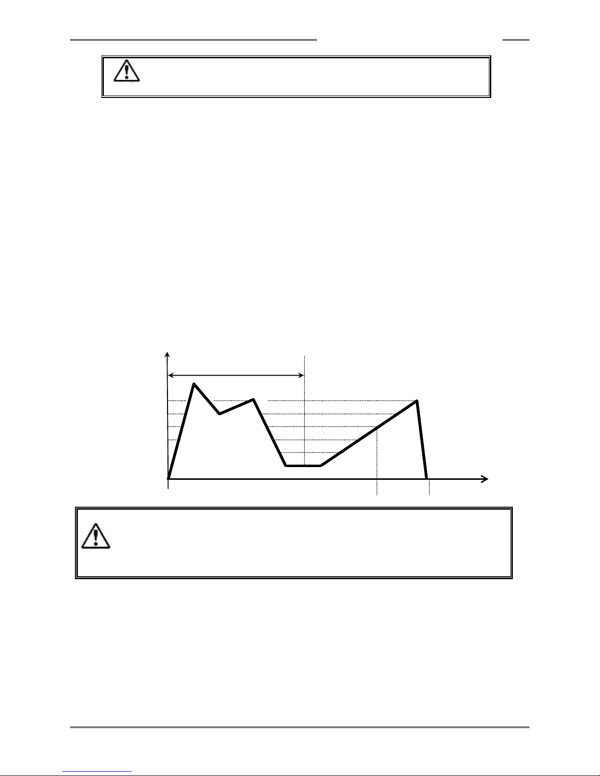
Chapter 6 Description of Operations
PAGE 6-27
The following judgments cannot be made unavailable.
・Peak torque check ・Final angle check ・Timeout check
●Torque Check [N•m]
•Peak Torque
The high and low limit values of the peak torque in the fastening operation are set. The fastening
operation is ended when the peak torque high limit value is exceeded during the fastening operation.
•Final Torque
The high and low limit values of the fastening torque at the point at which the standard angle is
attained are set.
•Snug Torque
The high limit value of the Snug torque during Snug torque detection is set.
•Starting Torque Inhibit
The starting torque inhibit high limit value after the start of the fastening operation is set. This can be
used for fastening in cases where the starting torque is high. The fastening operation is ended when,
during operation within D-No. 205 [Torque Inhibit Angle], the start torque inhibit high limit value is
exceeded.
Also, from the start of fastening to the point at which D-No. 205 [Torque Inhibit Angle] is attained,
torque-related set values besides the starting torque inhibit high limit are ignored.
111 Torque Inhibit
Limit
205 Torque Inhibit Angle
103 Standard Torque
109 2nd Torque
105 1st Torque
107 Snug Torque
1st Time
2nd Time
Angle (Time)
•When the torque inhibit check is enabled, the following set values are ignored within the
start torque inhibit angle from the start of fastening.
D-No. 103: Standard Torque, D-No. 104: Ramp Down Start Torque, D-No. 105: 1st Torque,
D-No. 107: Snug Torque, D-No. 109: 2nd Torque, D-No. 112: Rate 1 Start Torque, D-No. 113:
Rate 1 End Torque, D-No. 114: Rate 2 Start Torque, D-No. 115: Rate 2 End Torque, D-No.
116: Rate 3 Start Torque, and D-No. 117: Rate 3 End Torque.
Torque
Caution
Caution
Page 88

Chapter 6 Description of Operations
PAGE 6-28
●Angle Check [deg]
•Final Angle
The high and low limit values of the angle from the point of Snug torque detection to the end are set.
The fastening operation is ended when the angle high limit value is exceeded during the fastening
operation.
●Timeout Check [sec]
•1st Time
The high and low limit values of time (1st time) from the start of fastening to the detection of the 1st
torque or the 1st angle are set.
•2nd Time
The high and low limit values of time (2nd time) from after the detection of the 1st torque or the 1st
angle to the end of fastening are set.
In regard to the 1st time, the fastening operation is ended when the time at which the 1st torque or the
1st angle is detected falls short of the 1st time low limit. Also, with the 1st time and the 2nd time, the
fastening operation is ended when the time high limit is exceeded during the fastening operation.
Also, when 2 steps or 3 steps is selected as the number of fastening steps, the delay times between
fastening steps are not counted as being within the 1st time and the 2nd time.
*The time of the self-checking executed before the start of the fastening operation is not counted as
being within the cycle time.
●Rundown Revolutions Check [rev.]
•Rundown revolutions
The high and low limit values of the rundown revolutions from the fastening start point to the fastening
end point are set.
Page 89
Chapter 6 Description of Operations
PAGE 6-29
●Rate Check
Three rates can be used to monitor the fastening operation during the fastening operation.
A rate start torque (angle) and a rate end torque (angle) are set and the torque slope (slope of the
torque vs. angle) between the two points at the point at which the rate end torque (angle) is attained is
measured to make the judgment. (Example: 25N•m÷100deg=0.25N•m/deg).
The fastening operation is ended when the measurement value of each rate falls outside the the high
and low limit ranges.
The start torque (angle) and end torque (angle) of the respective rates can be set freely without any
relation to the order of the rates and the set values of the other rates.
[To Customers Using the FUSION Handheld Nutrunner System]
There are D-Nos. that are changed in name and function. Please
perform setting with reference to the correspondence table on the
following page.
117: Rate 3
End Torque
116: Rate 3
Start Torque
115: Rate 2
End Torque
114: Rate 2
Start Torque
113: Rate 1
End Torque
112: Rate 1
Start Torque
305: Rate 3 High Limit
206: Differential + Angle
207: Differential - Angle
209: Rate 1 End Angle
208: Rate 1 Start Angle
Caution
304: Rate 3 Low Limit
301: Rate 1 High Limit
302: Rate 2 Low Limit
303: Rate 2 High Limit
300: Rate 1 Low
Limit
211: Rate 2 End Angle
212: Rate 2 Start Angle
213: Rate 3 End Angle
212: Rate 3 Start Angle
Page 90
Chapter 6 Description of Operations
PAGE 6-30
•If the rate start torque (angle) cannot be detected during the fastening operation, the rate
check will not be performed.
•Under the following conditions, the torque (angle) at the end of fastening is judged as the
rate end torque (angle).
•If the set values are set so that rate start torque (angle) > rate end torque (angle).
•If the rate end torque (angle) cannot be detected during the fastening operation.
•Whether torque or angle is used as the rate start (end) point is set by the fastening
parameter D-No. 005 [Fastening Judgment Output 3].
●FUSION/HFC3000 Fastening Parameter (Rate) Correspondence Table
FUSION
Fastening Parameter
HFC3000
Fastening Parameter
Function
17 Threshold Torque
112 Rate 1 Start Torque
The torque value at the start point of
measurement of torque rate 1 is set.
15 1st Torque
(1st Rate End Torque)
113 Rate 1 End Torque
The torque value at the end point of
measurement of torque rate 1 is set.
1E 2nd Rate Start Torque
114 Rate 2 Start Torque
The torque value at the start point of
measurement of torque rate 2 is set.
18 CROS Torque
(2nd Rate End Torque • 3rd
Rate End Torque)
115 Rate 2 End Torque
The torque value at the end point of
measurement of torque rate 2 is set.
116 Rate 3 Start Torque
The torque value at the start point of
measurement of torque rate 3 is set.
13 Standard Torque
(3rd Rate End Torque)
117 Rate 3 End Torque
The torque value at the end point of
measurement of torque rate 3 is set.
208 Rate 1 Start Angle
The angle value at the start point of
measurement of torque rate 1 is set.
23 1st Angle
(1st Rate End Angle)
209 Rate 1 End Angle
The angle value at the end point of
measurement of torque rate 1 is set.
26 2nd Rate Start Angle
210 Rate 2 Start Angle
The angle value at the start point of
measurement of torque rate 2 is set.
24 CROS Angle
(2nd Rate End Angle • 3rd Rate
Start Angle)
211 Rate 2 End Angle
The angle value at the end point of
measurement of torque rate 2 is set.
212 Rate 3 Start Angle
The angle value at the start point of
measurement of torque rate 3 is set.
27 3rd Rate Start Angle
22 Standard Angle
(3rd Rate End Angle)
213 Rate 3 End Angle
The angle value at the end point of
measurement of torque rate 3 is set.
Caution
Page 91
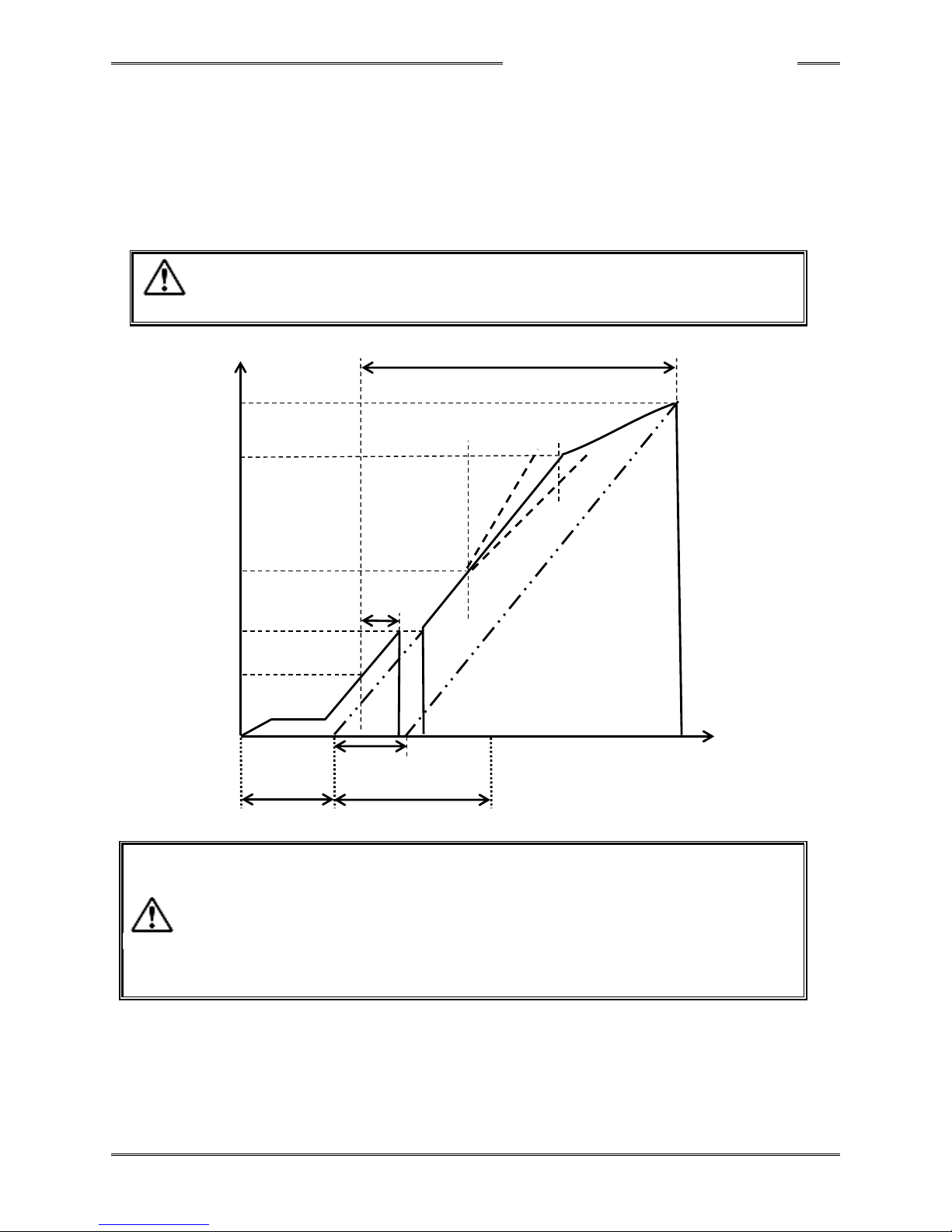
Chapter 6 Description of Operations
PAGE 6-31
Differential Angle Check
After the end of fastening, the differential angle, which is the difference between the seating point
(angle) of the final torque and the seating point (angle) calculated from the rate 2, is measured and
judged.
The seating point (angle) calculated from the rate 2 is calculated based on the rate 2 start torque
(angle) and the rate 2 end torque (angle).
When the differential angle check is available, it is judged whether or not the calculated differential
angle is within ranges based on the seating point (angle) calculated from the value of rate 2 as a
reference point.
•The value of the Differential angle of the fastening curve data and the value of the
differential angle of the fastening result contain a measurement error of a maximum of
5deg (±2.5deg).
•If the rate 2 start torque cannot be detected during the fastening operation, the differential angle
check will not be performed.
•Under the following conditions, the torque at the end of fastening is judged as the rate 2 end
torque.
•If the set values are set so that rate 2 start torque > rate 2 end torque.
•If the rate 2 end torque cannot be detected during the fastening operation.
202 Standard Angle
115 Rate 2
End Torque
114 Rate 2
Start Torque
303 Rate 2
High Limit
302 Rate 2
Low Limit
105 1st Torque
107 Snug Torque
Differential Angle
(Fastening Result)
Angle
103 Standard
Torque
203 1st Angle
Torque
206 Differential +Angle
207 Differential
-Angle
Seating point calculated from the Rate 2
Caution
Caution
Page 92
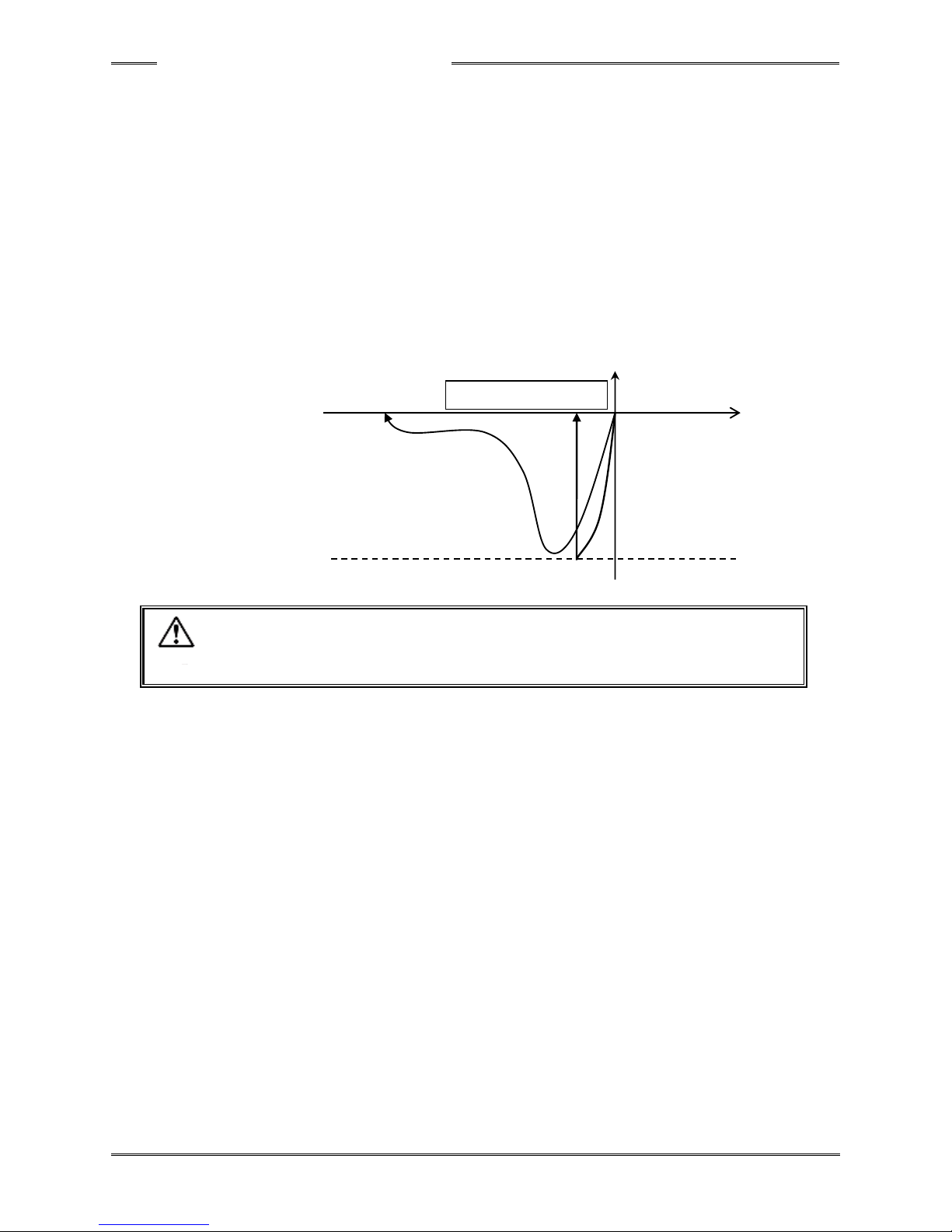
Chapter 6 Description of Operations
PAGE 6-32
Break away Torque Check
Whether or not the torque value during reverse rotation is within the high limit ranges is judged.
When D-No. 110 [Reverse Torque High Limit] is exceeded, the fastening operation is ended and
the abnormal state signal A09-08 “Reverse Torque Error” is generated.
♦Reverse Torque Judgment: [Neglect] ••• Manual reverse rotation by the PLC I/O input signal “REVERSE”
Manual reverse rotation operation by the lever on.
When D-No. 110 [Reverse Torque High Limit] is set “0”, The tool stops immediately
after starting. In manual reverse rotation operation, the reverse torque judgment is
always executed.
♦Reverse Torque Judgment: [Enable] ••• Reverse operation by the fastening option “Reverse After Fastening”
Reverse operation by the fastening option “Reverse Between 1-2 Steps”
Reverse operation by the fastening option “Reverse Between 2-3 Steps”
When D-No. 110 [Reverse Torque High Limit] is set “0” or Reverse Torque Judgment is
set “0”, Reverse Torque Judgment isignored.
・ D-No. 110 [Reverse Torque High Limit] limit is caused when you loose the bolt already
fastened over 5N・m of default setting in the case of the reverse operation and it automatically
stops for safety.
Caution
Torque
Angle
110: Reverse Torque High Limit
Break away Torque Check: [Enable]
A.09-08 is generated
Reverse stop
Page 93
Chapter 6 Description of Operations
PAGE 6-33
Current Value Warnings
After the end of the fastening operation, it is judged whether or not the peak current value
during operation is within the high and low limit ranges. If the peak current value during
operation falls below the low current limit or exceeds the high current limit, although the
controller outputs the ACCEPT axis judgment, the PLC layout output signal “Multi: Current
Limit Warning,” “Axis: Current Limit Warning,” “Axis: Current Low Warning,” or “Axis: Current
High Warning” is turned “ON.”
・The current value warning judgment cannot be made unavailable.
・As the full scale current, a value based on the motor used is set automatically in accordance
with the model of the controller. Do not change this value if there is no special reason to do
so.
Also, the current limit value limits the maximum value of the current during the fastening
operation. If a value lower than the full scale current is set, the fastening operation is executed so
that the current value does not exceed the value set as the current limit. The current limit value is
used to protect the motor during the execution of the torque recovery, which is an after-fastening
operation. When the current limit is exceeded, the fastening is stopped and the abnormal state
signal A05-01 “Servo Reply Error” is generated.
520: Full Scale Current Value:100%
523: Fastening Current Limit :100%
522: High Current Limit :100%
521: Low Current Limit : 0%
Caution
Page 94
Chapter 6 Description of Operations
PAGE 6-34
Fastening Speed and Time
With the HFC3000 Nutrunner System, the speed can be set according to the fastening operation.
1. Within the set 1st time high limit value, fastening up to the 1st torque or the 1st angle is performed. Also
within the 1st time, the following fastening operations are executed.
1-1. Within the time set as the initial time, operation at the initial speed is performed.
The initial time is set to alleviate the shock at the start of fastening and to enable fitting of the bolt and
the socket, etc.
1-2. After the end of the initial time, rotation at the freerun speed is performed up to the number of
revolutions set as the freerun revolutions. However, if rotation has already been performed for the
number of revolutions set as the freerun revolutions during the initial time, the speed is changed from
the initial speed to the 1st speed.
1-3. When the ramp down start torque is detected or rotation corresponding to the freerun revolutions has
been performed, the speed is changed from the freerun speed to the 1st speed. The operation is
continued until the 1st torque or the 1st angle is detected or the 1st time high limit value is reached.
The 1st speed is set so that the speed changes to it immediately before the bolt is seated to enable
seating to be attained without applying an excessive load to the tool.
402: 1st Speed
504: Rundown Revolution High Limit
404: 3rd Speed
403: 2nd Speed
503: Rundown Revolution Low Limit
500: Freerun Revolutions
310: Initial Time
1st Time
2nd Time
400: Initial Speed
401: Freerun Speed
1-1
1-2
1-3
315: Torque
Recovery Time
Page 95
Chapter 6 Description of Operations
PAGE 6-35
2. When the 1st torque or the 1st angle is detected, the 1st time ends and the 2nd time is started. The 1st
torque and the 1st angle are the points of changing from the 1st speed to the 2nd speed and are the points
of synchronization of the 2nd step.
3. In the 2nd step, the fastening operation to the standard torque or the standard angle is performed at the 2nd
speed until the 2nd time high limit value is reached. If the target value cannot be attained by the 2nd time
high limit value, the REJECT fastening result is output.
4. If the 2nd torque or the 2nd angle is detected before the standard torque or the standard angle, the speed is
changed from the 2nd speed to the 3rd speed. Also, the 2nd torque and the 2nd angle are the points of
synchronization of the 3rd step.
・ If D-No. 109 [2nd Torque] is set to 95 ~ 100% of D-No. 103 [Standard Torque], the fastening speed
is automatically set to 3rpm after the detection of the 2nd torque.
・ Use of this function is not recommended for fastening a soft joint. The abnormal state signal
A.08-10 “Overload Error” may be generated.
402: 1st Speed
504: Rundown Revolution High Limit
404: 3rd Speed
403: 2nd Speed
503: Rundown Revolution Low Limit
500: Freerun Revolutions
310: Initial Time
315: Torque
Recovery Time
1st Time
2nd Time
400: Initial Speed
401: Freerun Speed
2 4 3
Caution
Page 96
Chapter 6 Description of Operations
PAGE 6-36
6-6 Parameter Structure
Parameter No. P. 64
Parameter No. P. 63
Parameter No. P. 62
Parameter No. P. 03
Parameter No. P. 02
Parameter No. P. 01
000: Fastening Method
001: Fastening Steps
002: Fastening Option
003: Judge Item 1
004: Judge Item 2
~
~
Parameter No. SYS
System Parameters
000: Torque Unit
001: Software Version
002: Amplifier Version
003: System Indication
503:Touch Panel Connection
Port Number
~
Page 97
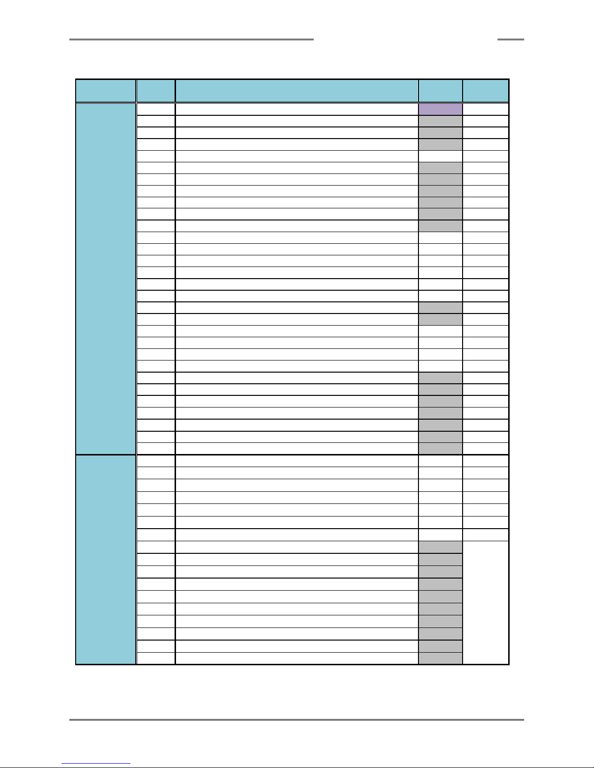
Chapter 6 Description of Operations
PAGE 6-37
System Parameters
<System Parameters> Par No. Indication: SYS
Item
D-No.
Contents
Setting
change
controller
s
controller
Information 1
000
Torque controller
001
Software Version
002
Amplifier Version
003
System Indication
004
Spindle Adapter Gear Ratio
○ 005
For Adjustment by the Manufacturer
006
For Adjustment by the Manufacturer
007
Communication Axis Indication
008
Axis Cycle Count (×1 million)
009
Axis Cycle Count (×1)
010
controller Maximum Current
011
IP Address (upper 6 digits): 192.168
○
012
IP Address (lower 6 digits): 11.10
○ 013
Subnet Mask (upper 6 digits): 255.255
○ 014
Subnet Mask (lower 6 digits): 255.0
○
015
Default Gateway (upper 6 digits): 192.168
○ 016
Default Gateway (lower 6 digits): 11.1
○ 017
MAC Address (upper 6 digits): 001F98
018
MAC Address (lower 6 digits): 001000
019
RTC: Year/Month/Day “130725” July 25, 2013
○
020
RTC: Time “123456” 12:34 56
○ 021
Erase Fastening Record/Format CF Card
○ 022
Parameter Copy
○
023
For Adjustment by the Manufacturer
024
For Adjustment by the Manufacturer
025
For Adjustment by the Manufacturer
026
controller SW1 Setting state
027
controller SW2 Setting state
028
For Adjustment by the Manufacturer
029
For Adjustment by the Manufacturer
Options
033
System Option 1
○
034
System Option 2
○
035
System Option 3
○ 036
Gear head Type
○ 037
Start Switch Level
○ 038
Rapid Switch level
○
039
CW/CCW Switch Level
○ 040
For Adjustment by the Manufacturer
Cannot
be
changed.
041
// 042
// 043
// 044
// 045
// 046
//
047
//
048
//
049
//
Page 98
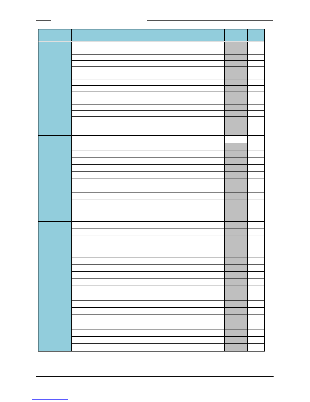
Chapter 6 Description of Operations
PAGE 6-38
Item
D-No.
Contents
Setting
change
contro
llers
Connected
Tool Settings
100
Connected Tool No.
101
Connected Tool Information “015-P1”
102
Connected Tool CAL Torque Decimal Point Position
103
Connected Tool CAL Torque
Nm
104
Connected Tool CAL Voltage
V 105
Connected Tool ZERO Voltage
V
106
Connected Tool Internal Gear Ratio (×100)
107
Connected Tool Serial No. (upper 3 digits)
108
Connected Tool Serial No. (lower 4 digits)
109
Connected Tool Rotation Direction
110
Connected Tool Order No. (upper 2 digits)
111
Connected Tool Order No. (lower 5 digits)
112
Connected Tool Cycle Count (×1 million)
113
Connected Tool Cycle Count (×1)
114
Connected Tool Maximum Current
A
controller
Information 2
200
controller Setting Tool No.
○
201
controller Setup Tool Information “015M50”
202
Parameter Setting File Version
203
Sequence Setting File Version
204
PLC Output Layout Setting File Version
205
Fieldbus Setting File Version
206
Fieldbus Message Setting File Version
207
RS232C Input/Output Setting File Version
208
controller RS232C-1 Communication Speed
bps
209
controller RS232C-1 Parity
210
controller RS232C-1 Stop Bit
bit
211
controller RS232C-1 Word Length
bit
Option
Information1
300
Connected Fieldbus Information
301
ANYBUS-CC Version
302
controller Setting Fieldbus Information
303
Station No. (Node Address) (1 ~ 64 or 0 ~ 63)
304
Communication Speed (0 ~ 4)
305
Occupied Stations (1, 2, 3, 4)
306
Extended Cyclic Setting (1, 2, 4, 8)
307
I/O Setting Byte Length “PLC → MASTER Axis”
308
I/O Setting Byte Length “Master Axis → PLC”
309
Message Block Byte Length
310
Message Setting Byte Length “PLC → MASTER Axis”
311
Message Setting Byte Length “Master Axis → PLC”
312
IP Address (upper 6 digits)
313
IP Address (lower 6 digits)
314
Subnet Mask (upper 6 digits)
315
Subnet Mask (lower 6 digits)
316
Gateway (upper 6 digits)
317
Gateway (lower 6 digits)
Page 99
Chapter 6 Description of Operations
PAGE 6-39
Item
D-No.
Contents
Setting
change
contro
llers
Option
Information2
400
CF Card Storage Capacity
% 401
RS232C-2 Communication Speed
bps
402
RS232C-2 Parity
403
RS232C-2 Stop Bit
bit
404
RS232C-2 Word Length
bit
405
Not used
406
Not used
407
Not used
408
Not used
409
ID Input Selection
Touch Panel
500
Touch Panel Connection IP Address (upper 6 digits)
○ 501
Touch Panel Connection IP Address (lower 6 digits)
○
502
Touch Panel Language Select
○
503
Touch Panel Connection Port Number
○
Page 100
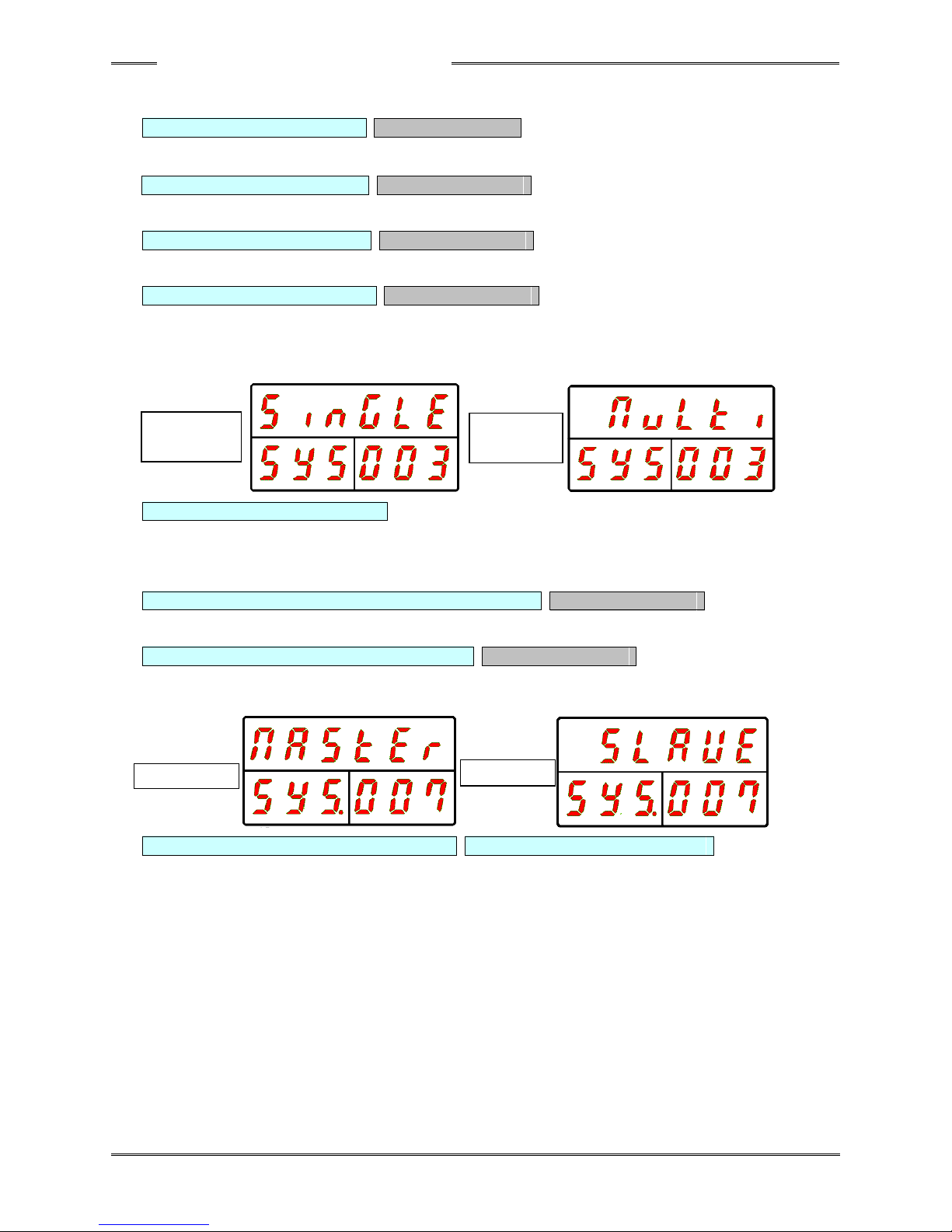
Chapter 6 Description of Operations
PAGE 6-40
System Parameters (controller Information 1)
D-No.000 Torque controller Cannot be changed.
All fastening parameters within the controller will have the same torque unit.
D-No. 001 Software Version Cannot be changed.
This is the software version of the controller.
D-No. 002 Amplifier Version Cannot be changed.
This is the amplifier version.
D-No. 003 System Indication Cannot be changed.
This indicates whether the controller is a multi system or a single system.
This is also used to change between the multi system and the single system.
The handheld tool operates only in the single system setting.
D-No. 004 External Gear Ratio Setting range: 0.300 ~ 3.000, standard setting: 1.000
When a gear is installed at the top of the tool, the gear ratio with respect to the output
shaft of the tool is set here.
Do not use a value other than 1.000 as long as an external offset gear is not used.
D-No.005 / 006 For adjustment by the manufacturer Cannot be changed.
Not used.
D-No. 007 Communication Axis Indication Cannot be changed.
This indicates whether the controller is the MASTER Axis for (PC) communication and
I/O (PLC) communication or is a SLAVE Axis.
D-No. 008 Axis Cycle Count (×1 million) D-No. 009 Axis Cycle Count (×1)
These indicate the count at which the controller performed the fastening operation.
* When the count is less than 1 million times, [------] is indicated for D-No. 008.
Single
System
Multi
System
MASTER Axis
SLAVE Axis
 Loading...