

Page 1

AFC3000E-FB-DN-1
MFC
-DN
expansion Unit
Devicenet
Fieldbus
Page 2

FU
SION
= DC Hand
Tool
EN
Revision History
Devicenet Fieldbus Expansion Unit
Revision Date
08/20/2014 AFC3000E-FB-DN-1 First Release
01/19/2018 AFC3000E-FB-DN-1 Minor revision - Message Output formats fixed (pg.13-24)
Manual No. Contents of Revision
Manual Numbering Convention
AFC3000E-FB-DN-1
DSP1500 = Servo Press
DSP1500
DSP1500 = Servo Press
DSP1500DSP1500
AFC3000 = Nutrunner
AFC1500
AFC1500 = Nutrunner
AFC1500AFC1500
FUSION
FUSION = DC Hand Tool
FUSIONFUSION
E = English Version
S = Spanish Version
*Japanese Version furnished by DDK
uses DDK numbering convention.
Version Number
(Major Revision Level)
CC = CC-Link
DN = DeviceNet
PB = Profibus
PN = ProfiNet
= Ethernet-I/P
HW = Hardware Operation Manual
SW = Software Manual
FB = Fieldbus Manual
Any questions regarding the contents of this document or any related matter should be
directed to FEC Automation Systems at (586) 580-2622, faxed to (586) 580-2620 or emailed to
The information set forth in the following document is the property of
This document shall not be released to or copied for any person and/or organization without
the expressed prior consent of FEC Automation Systems.
Unauthorized reproduction or distribution of this manual is strictly prohibited.
Please contact FEC Automation Systems if you require additional copies.
PAGE 2
FEC Automation Systems.
Page 3

Station
Slave Stations of Other
Axis
Axis
Devicenet Fieldbus Expansion Unit
Forward
This manual is intended as a supplement to the AFC3000 Hardware Operation Manual and should be
used in conjunction with information provided in that manual. FEC recommends reading that manual
before the contents of this manual (which only applies to systems requiring the optional Ethernet I/P
interface).
Devicenet Interface
The AFC3000 Devicenet interface conforms to the open field network known as Devicenet. Control of tools
and transactions of message information are executed by Devicenet explicit message communication.
Due to conformance with the open field network Devicenet System, connections with Devicenet devices
(master/slave) of other manufacturers are enabled.
Also, remote I/O communication and message communication can be executed at the same time.
System Structure (Devicenet)
PLC (Devicenet Master Station)
Remote I/O Communication
Message Communication
Devicenet
Slave
MASTER
(1st
Spindle)
Devicenet
Manufacturers
2nd
AFC3000 Devicenet System
3rd
32nd
Spindle
SLAVE
PAGE 3
Page 4

Devicenet Fieldbus Expansion Unit
Description of the Hardware (Devicenet)
Module
Status
LED
DeviceNet
Connector
Network
Status
LED
PAGE 4
Page 5

Wire
●
EDS File
Devicenet Fieldbus Expansion Unit
An EDS file is an information file related to the communication specifications of Devicenet compatible
devices and a separate, individual file exists for each device. The EDS file is necessary for using the
Devicenet PLC configuration software to connect the MFC-EN and the PLC.
The EDS file is included in the installation CD for the AFC3000 User Console or may be downloaded from
the FEC website. Please refer to the instruction manual for the Devicenet configuration software concerning
the appropriate method for using the EDS file.
●
Module Pin Configuration
No. Signal
1
2
3
4
5
V- Black Power cable - side
CAL L Blue
SHIELD - Cable Shield
CAL H White Communication data High
V+ Red Power cable + side
Color
Communication data Low
side
Description
Manufacturer: Phoenix Contact
Type: Connector plug
Model: MSTB 2.5/5-ST-5.08 AU M
Applicable wire size: AWG 14 to 23 or 0.25mm2 to 2.5mm2
* The connector is included with the equipment.
(To be wired by customer)
* The cable is not included with the equipment. Please prepare a LAN cable of Category 5e or higher on
your own equipment. Please prepare these on your own.
・・・・
Be sure to connect the cable with all power turned OFF.
Caution
PAGE 5
Page 6

●
List of LED Indications
The module LEDs indicate the states of the nodes of the AFC3000 DeviceNet interface and the
network state.
A
B
Network
Status
LED
Module
Status
LED
LED
A : Network
Status LED
Color State Details
OFF Off Offline Offline or power is not supplied.
Green
Red
Red/
Green
OFF Off Power OFF Power is not supplied.
Green
Red
Red/
Green
Devicenet Fieldbus Expansion Unit
B : Module
Status LED
Lit up Online Communicating normally.
Flash
Lit up Error A critical error has occurred.
Flash Connection timeout A connection timeout has occurred once or more.
Lit up Repeated Test mode
Lit up Online Normal state
Flash
Lit up
Flash
Lit up Repeated Test mode
Connection not
established
Connection not
established
Error
Error
Although online, connection is not established.
Due to incomplete configuration or connection failure,
the device must be re-recognized.
A critical error has occurred.
A recoverable error has occurred.
PAGE 6
Page 7

Devicenet Fieldbus Expansion Unit
I/O Signal Specifications (Devicenet)
Maximum
Setting
Standard
Setting
MASTER Spindle →
32bytes (256
32bytes (256
I/O Input/Output Message Input/Output
PLC
points
points
PLC → MASTER
Spindle
) 12bytes (96
) 8bytes (64
points
points
MASTER Spindle →
PLC
) 2048
) 2048
word
word
(4096
(4096
bytes
bytes
PLC → MASTER
Spindle
) 16 word (32bytes)
) 16 word (32bytes)
●●●● AFC3000 Devicenet System Signal Specifications (PLC →→→→ MASTER Spindle)
・
Number of MASTER Spindle Input Points 4 words 8 bytes (256 points)
FEC Input signals (PLC Outputs) are factory set and cannot be changed.
Word No. BIT Signal Word No. BIT Signal
0 STOP
1 RESET 1 SEQ SELECT No.18
2 REVERSE 2 SEQ SELECT No.19
3 START 3 SEQ SELECT No.20
4 SEQ SELECT BIT 0 4 SEQ SELECT No.21
5 SEQ SELECT BIT 1 5 SEQ SELECT No.22
6 SEQ SELECT BIT 2 6 SEQ SELECT No.23
No.01
7 SEQ SELECT BIT 3 7 SEQ SELECT No.24
8 SEQ SELECT BIT 4 8 SEQ SELECT No.25
No.03
9 CYCLE COUNT UP 9 SEQ SELECT No.26
10 CYCLE COUNT CLEAR 10 SEQ SELECT No.27
11 SEQ SELECT No. ENABLE 11 SEQ SELECT No.28
12 INPORT 1 12 SEQ SELECT No.29
13 INPORT 2 13 SEQ SELECT No.30
14 INPORT 3 14 SEQ SELECT No.31
15 INPORT 4 15 SEQ SELECT No.32
0 SEQ SELECT No.1
1 SEQ SELECT No.2 1 BYPASS SPDL No.2
2 SEQ SELECT No.3 2 BYPASS SPDL No.3
3 SEQ SELECT No.4 3 BYPASS SPDL No.4
4 SEQ SELECT No.5 4 BYPASS SPDL No.5
5 SEQ SELECT No.6 5 BYPASS SPDL No.6
6 SEQ SELECT No.7 6 BYPASS SPDL No.7
No.02
7 SEQ SELECT No.8 7 BYPASS SPDL No.8
8 SEQ SELECT No.9 8 BYPASS SPDL No.9
No.04
9 SEQ SELECT No.10 9 BYPASS SPDL No.10
10 SEQ SELECT No.11 10 ID DATA CLEAR
11 SEQ SELECT No.12 11 ID SELECT ENABLE
12 SEQ SELECT No.13 12
13 SEQ SELECT No.14 13
14 SEQ SELECT No.15 14
15 SEQ SELECT No.16 15
0 SEQ SELECT No.17
0 BYPASS SPDL No.1
PAGE 7
Page 8

The allocation of the input signals is fixed (cannot be changed).
(and cannot be used by other
Unit is to be put in the BYPASS mode, set the corresponding signal
among the BYPASS No. # (1 to 32) signals to “ON” with the START signal of the Unit
for PC
BYPASS No. # (1 to 32) signals
at Unit will be ignored as if it does not
ignals is set to “ON” with the BUSY
being in the “ON” state, the sequence judgment may result
Devicenet Fieldbus Expansion Unit
Word No. BIT Signal Word No. BIT Signal
0 BYPASS SPDL No.11
0 BYPASS SPDL No.27
1 BYPASS SPDL No.12 1 BYPASS SPDL No.28
2 BYPASS SPDL No.13 2 BYPASS SPDL No.29
3 BYPASS SPDL No.14 3 BYPASS SPDL No.30
4 BYPASS SPDL No.15 4 BYPASS SPDL No.31
5 BYPASS SPDL No.16 5 BYPASS SPDL No.32
6 BYPASS SPDL No.17 6
No.05
7 BYPASS SPDL No.18 7
8 BYPASS SPDL No.19 8
No.06
9 BYPASS SPDL No.20 9
10 BYPASS SPDL No.21 10
11 BYPASS SPDL No.22 11
12 BYPASS SPDL No.23 12
13 BYPASS SPDL No.24 13
14 BYPASS SPDL No.25 14
15 BYPASS SPDL No.26 15
* The word No. at the PLC side differs according to the setting of the node address, etc., so please be sure
to confirm before using. Please refer to the AFC3000 Operation Manual, Section 5-3-2 and 5-3-3 for
description of the respective signals.
The unused area of the inputs is also secured
Caution
Cautio
devices).
Be careful of the following points when using the BYPASS No. # (1 to 32) signals.
If a certain
being in the “OFF” state and the BUSY signal of the MASTER Spindle
communication and I/O (PLC) control being in the “OFF” state.
When fastening is executed with any of the spindle
in the “ON” state, the fastening judgment of th
exist.
Also, when any of the BYPASS No. # (1 to 32) s
of the MASTER Spindle
in REJECT.
PAGE 8
Page 9

Devicenet Fieldbus Expansion Unit
●
AFC3000 Devicenet System Signal Specifications (MASTER Spindle →→→→ PLC)
・
Number of MASTER Spindle Output Points 32 bytes (256 bits)
The table below is an example of the Output mapping using Ethernet I/P. Output bits (256) are
allowed to be user-programmed using the AFC3000 User Console Software.
The allocation of the signals can be set on any bit/pin through the “PLC Output Layout” setting function
of the AFC3000 Software.
Please refer to “5-3-4 PLC Output Layout” of the <<AFC3000 Operation Manual>> for list of available
output signals (Master and individual spindle signals)
EXAMPLE ONLY: Actual signal placement may vary upon user configuration
Word No. BIT Signal Word No. BIT Signal
Output word
No. 1
Output
Signal
Setting
Example
Output word
No. 2
Output
Signal
Setting
Example
0 TOTAL REJECT
1 TOTAL ACCEPT 1 SEQ No.18 SELECTED
2 TOTAL ABNORMAL 2 SEQ No.19 SELECTED
3 TOTAL READY 3 SEQ No.20 SELECTED
4 TOTAL BUSY 4 SEQ No.21 SELECTED
5 END 5 SEQ No.22 SELECTED
6 SEQ SELECT BIT 0 6 SEQ No.23 SELECTED
7 SEQ SELECT BIT 1 7 SEQ No.24 SELECTED
8 SEQ SELECT BIT 2 8 SEQ No.25 SELECTED
9 SEQ SELECT BIT 3 9 SEQ No.26 SELECTED
10 SEQ SELECT BIT 4 10 SEQ No.27 SELECTED
Output word
No. 3
Output
Signal
Setting
Example
11 SPINDLE IN BYPASS 11 SEQ No.28 SELECTED
12 DATA AVAILABLE 12 SEQ No.29 SELECTED
13 CURRENT WARNING 13 SEQ No.30 SELECTED
14 CAL WARNING 14 SEQ No.31 SELECTED
15
ZERO LEVEL WARNING
0 SEQ No.1 SELECTED
1 SEQ No.2 SELECTED
2 SEQ No.3 SELECTED
3 SEQ No.4 SELECTED
4 SEQ No.5 SELECTED
5 SEQ No.6 SELECTED
6 SEQ No.7 SELECTED
7 SEQ No.8 SELECTED
8 SEQ No.9 SELECTED
9 SEQ No.10 SELECTED
10 SEQ No.11 SELECTED
11 SEQ No.12 SELECTED
12 SEQ No.13 SELECTED
13 SEQ No.14 SELECTED
14 SEQ No.15 SELECTED
15 SEQ No.16 SELECTED
Output word
No. 4
Output
Signal
Setting
Example
0 SEQ No.17 SELECTED
15 SEQ No.32 SELECTED
0 REJECT No.1
1 ACCEPT No.1
2 ABNORMAL No.1
3 BYPASS No.1
4 REJECT No.2
5 ACCEPT No.2
6 ABNORMAL No.2
7 BYPASS No.2
8 REJECT No.3
9 ACCEPT No.3
10 ABNORMAL No.3
11 BYPASS No3
12 REJECT No.4
13 ACCEPT No.4
14 ABNORMAL No.4
15 BYPASS No.4
PAGE 9
Page 10

Devicenet Fieldbus Expansion Unit
Word No. BIT Signal Word No. BIT Signal
0 REJECT No.5
1 ACCEPT No.5 1 RUN REV LO REJ No.5
2 ABNORMAL No.5 2
3 READY No.5 3
Output word
No. 5
Output
Signal
Setting
Example
4 BUSY No.5
5 BYPASS No.5
6 TORQUE HOLD No.5
7 PAR SEL (BIT0) No.5
8 PAR SEL (BIT1) No.5
9 PAR SEL (BIT2) No.5
10 PAR SEL (BIT3) No.5
11 PAR SEL (BIT4) No.5
12 TORQUE HI REJ No.5
13 TORQUE LO REJ No.5
14 FTQ HI REJ No.5
15 FTQ LO REJ No.5
0 SNUG TQ HI REJ No.5
Output word
No. 7
Output
Signal
Setting
Example
1 TQ INHIBIT HI REJ No.5
Output word
No. 6
Output
Signal
Setting
Example
2 F ANGLE HI REJ No.5
3 F ANGLE LO REJ No.5
4 DIFF + ANG REJ No.5
5 DIFF – ANG REJ No.5
6 RATE 1 HI REJ No.5
7 RATE 1 LO REJ No.5
8 RATE 2 HI REJ No.5
9 RATE 2 LO REJ No.5
10 RATE 3 HI REJ No.5
11 RATE 3 LO REJ No.5
12 1ST TIME HI REJ No.5
13 1ST TIME LO REJ No.5
14 2ND TIME HI REJ No.5
15 2ND TIME LO REJ No.5
Output word
No. 8
Thru
No. 16
Output
Signal
Setting
Example
The example above (output word 5-7) shows an example of all available signals for each spindle.
While normally not all signals are used, any of the signals (for each spindle) can be preset
(programmed using the AFC3000 software) to any output bit.
0 RUN REV HI REJ No.5
LO CUR LIMIT WARNING No.5
HI CUR LIMIT WARNING No.5
4
CURRENT WARNING No.5
5
CAL VOLTAGE WARNING No.5
6
ZERO VOLT WARNING No.5
7
JUDGE COMBO (BIT1) No.5
8
JUDGE COMBO (BIT2) No.5
9
JUDGE COMBO (BIT3) No.5
10
JUDGE COMBO (BIT4) No.5
11
JUDGE COMBO (BIT5) No.5
12
JUDGE COMBO (BIT6) No.5
13
JUDGE COMBO (BIT7) No.5
14
JUDGE COMBO (BIT8) No.5
15
0
1
2
3
4
5
6
7
8
9
10
11
12
13
14
15
* The word No. at the PLC input side differs according to the setting of the node address, etc., so please be
sure to confirm before using. Please refer to the AFC3000 Operation Manual, Section 5-3-2 and 5-3-3 for
description of the respective signals.
The unused area of Word 01 to 16 is also secured.
Caution
PAGE 10
Page 11

The standard set values are set as the factory settings in the
Devicenet Fieldbus Expansion Unit
Fieldbus Setting (Devicenet)
The fieldbus settings are set in the “Fieldbus Setting” menu of the AFC3000 User Console. The following
setting window is displayed when “Multi” → “Fieldbus Setting” is selected at the menu bar.
In the Bus Type Select/communication window, selection of the fieldbus type, uploading, downloading,
and verification of fieldbus settings with respect to the Unit, and browsing and saving of fieldbus settings
with respect to the PC can be performed.
-
Unit. Do not change the settings unless there is a special
Caution
reason.
-
Be sure to perform backup before changing the fieldbus
settings of the Unit.
● Bus Type Select: The type of bus is selected from the list. Also, when ”Upload” is executed, the bus
type is judged automatically and reflected in the selection part.
● Configuration File
・
Browse: A fieldbus configuration file (*.nrfcf) is read from the PC.
・
Save: A fieldbus configuration file (*.nrfcf) is saved in the PC.
● Upload: The fieldbus settings are read from the MASTER Spindle for PC communication
and I/O (PLC) control.
● Download: The fieldbus settings are written into the MASTER Spindle for PC communication
and I/O (PLC) control. (Re-activate the control power after writing.)
● Verify: The fieldbus settings of the MASTER Spindle for PC communication and I/O
(PLC) control and the fieldbus settings in the User Console are compared.
PAGE 11
Page 12
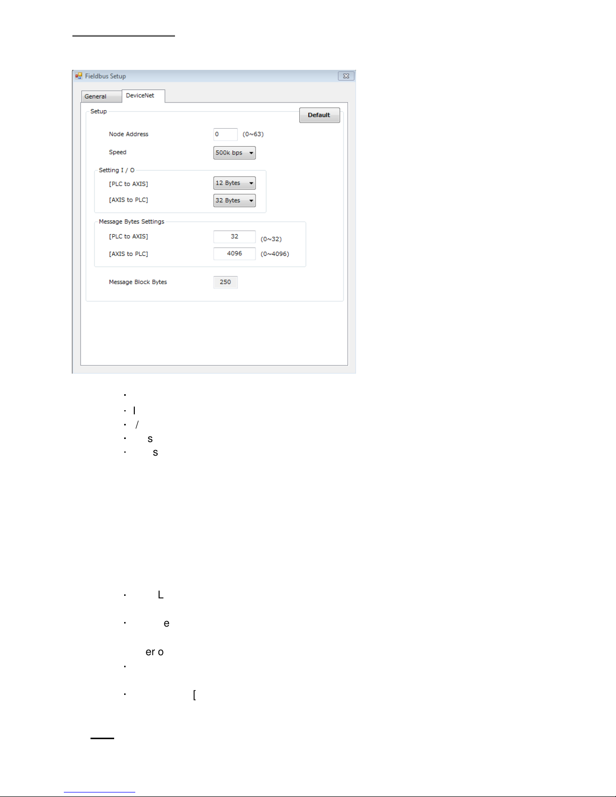
In the Devicenet screen (of the AFC3000 Software), setting of the Devicenet interface is performed. The
network settings, the I/O size, and the message size can be changed.
Devicenet Fieldbus Expansion Unit
● Default (the settings are set to the factory settings when this is selected)
・
Node Address: 0
・
I/O Setting Data Length [PLC to MASTER Spindle]: 8 bytes [64 bits]
・
I/O Setting Data Length [MASTER Spindle to PLC]: 32 bytes [256 bits]
・
Message Data Length [PLC to MASTER Spindle]: 32 bytes
・
Message Data Length [MASTER Spindle to PLC]: 4096 bytes
* The number of message block bytes is fixed at 250 bytes.
●
Communication Speed
Setting range: 156kbps, 250kbps, 500kbps
●
Node Address
Setting range: 0 to 63
●
I/O setting
・
Data Length [PLC to MASTER Spindle]
・
Data Length [MASTER Spindle to PLC]
●
The Number of Message Bytes Settings
・
Data Length [PLC to MASTER Spindle]
・
Data Length [MASTER Spindle to PLC]
Note: Power must be cycled if any of this configuration is changed and downloaded to the Master
controller
Setting range: 2 bytes [16 bits] to 12 bytes [96 bits]
Setting range: 2 bytes [16 bits] to 32 bytes [256 bits]
Setting range: 0 byte [0 bit] to 32 bytes
Setting range: 0 byte [0 bit] to 4096 bytes
PAGE 12
Page 13
Caution
Devicenet Fieldbus Expansion Unit
Fieldbus Message Setting (MASTER Spindle →→→→ PLC)
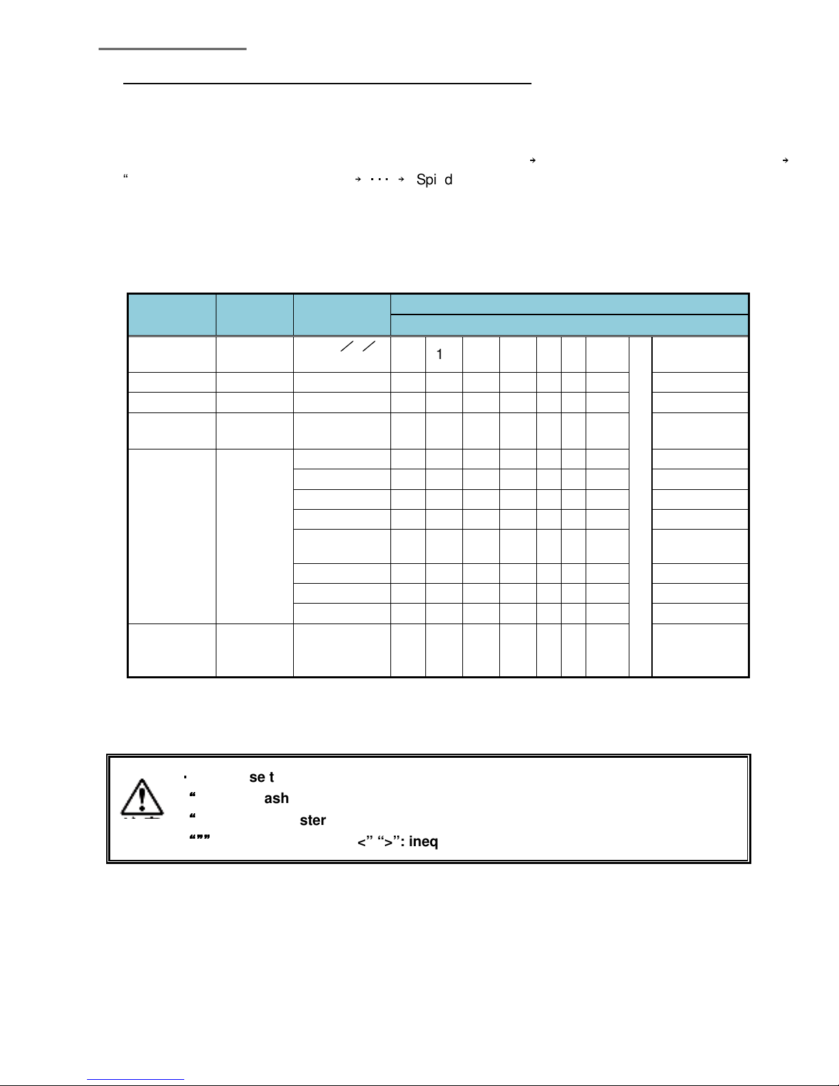
The message information output from the MASTER Spindle for PC communication and I/O (PLC) control
is set in the AFC3000 User Console software. The maximum size of the message output that can be
handled is 4096 bytes.
The output order of the message data is: “Multi Format Data” → “Spindle format data of Spdl. No. 1” →
“Spindle format data of Spdl. No. 2” →
The message output format is selectable (in the AFC3000 Software) to output either BCD format or
ASCII format, both examples are listed below.
Please contact the PLC manufacturer regarding the setting at the PLC side.
● Multi Format Output Items (BCD Format)
・・・ →
“Spindle format data of Spdl. No. 32.”
Output
Items
Date 4
Time 4 12:34:56 12 34 56 00 - - - ID *1 32 ABCDEF A B C D E F NUL
SEQ No.
(1 to 32)
SEQ
Judgment
*2
SEQ
Cycle
Count
*1: The ID is fixed at 32 bytes (16 words) and is output in ASCII format. NULL letters are set as unset
values.
*2: Please refer to AFC3000 Operation Manual, “Sequence Judgment” regarding the details of SEQ
Judgment.
Number
of Bytes
2 2 00 02 - - - - - -
2
4 123456 00 12 34 56 - - - -
Fastening
Data
2013/5
28
REJECT 00 01 - - - - - ACCEPT 00 02 - - - - - -
ABNORMAL 00 04 - - - - - -
STOP 00 08 - - - - - -
RESET
STOP
BYPASS 00 20 - - - - - -
START OFF 00 40 - - - - - -
IN CYCLE 00 80 - - - - - -
LSB (1word) PLC Input Data MSB (16word)
/
20 13 5 28 - - -
00 10 - - - - - -
Multi Format
-
NUL
~
・・・・
Do not use the following characters when inputting the ID data.
““““
∖∖∖∖”: backslash (yen mark), “/”: slash,
““““
:”: colon, “*”: asterisk, “?”: question mark,
“””
“””
: double quotation, “<” “>”: inequality signs, “|”: pipe sign
“””“””
PAGE 13
Page 14
]
]
]
]
]
]
C
] ]
Caution
Devicenet Fieldbus Expansion Unit
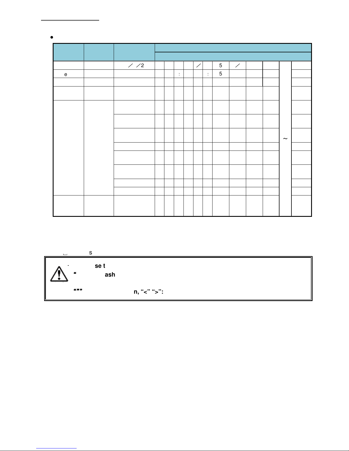
●Multi Format Output Items (ASCII Format)
Output
Items
Date 10
Time 8 12:34:56
ID*1
SEQ No.
(1 to 32)
SEQ
Judgment
*2, *3
SEQ
Cycle
Count
Number
of Bytes
32 ABCDEF A B C D E F NUL NUL NUL NUL NUL
2 2
4
8 123456
Fastening
Data
2013/5/28
REJECT R E J
ACCEPT A C C
ABNORMAL A B
STOP S T
RESET STOP R S
BYPASS B Y
START OFF S O
IN CYCLE I N
PLC Input Data “Letter String”
2 0 1 3
1 2
:
2
N
O
T
P
F
1 2 3 4 5 6
/ 0 5
3 4
P
F
Y
Multi Format
/
2 8
:
5 6
~
*1: The number of output bytes of the ID is fixed at 32 bytes (16 words). NULL letters are set as unset
values.
*2: Please refer to AFC3000 Operation Manual, “Sequence Judgment” regarding the details of SEQ
Judgment.
*3: ␣ (20H) is the ASCII code for (space).
・・・・
Do not use the following characters when inputting the ID data.
““““
∖∖∖∖”: backslash (yen mark), “/”: slash,
“:”: colon, “*”: asterisk, “?”: question mark,
“””
“””
: double quotation, “<” “>”: inequality signs, “|”: pipe sign
“””“””
PAGE 14
Page 15
Devicenet Fieldbus Expansion Unit
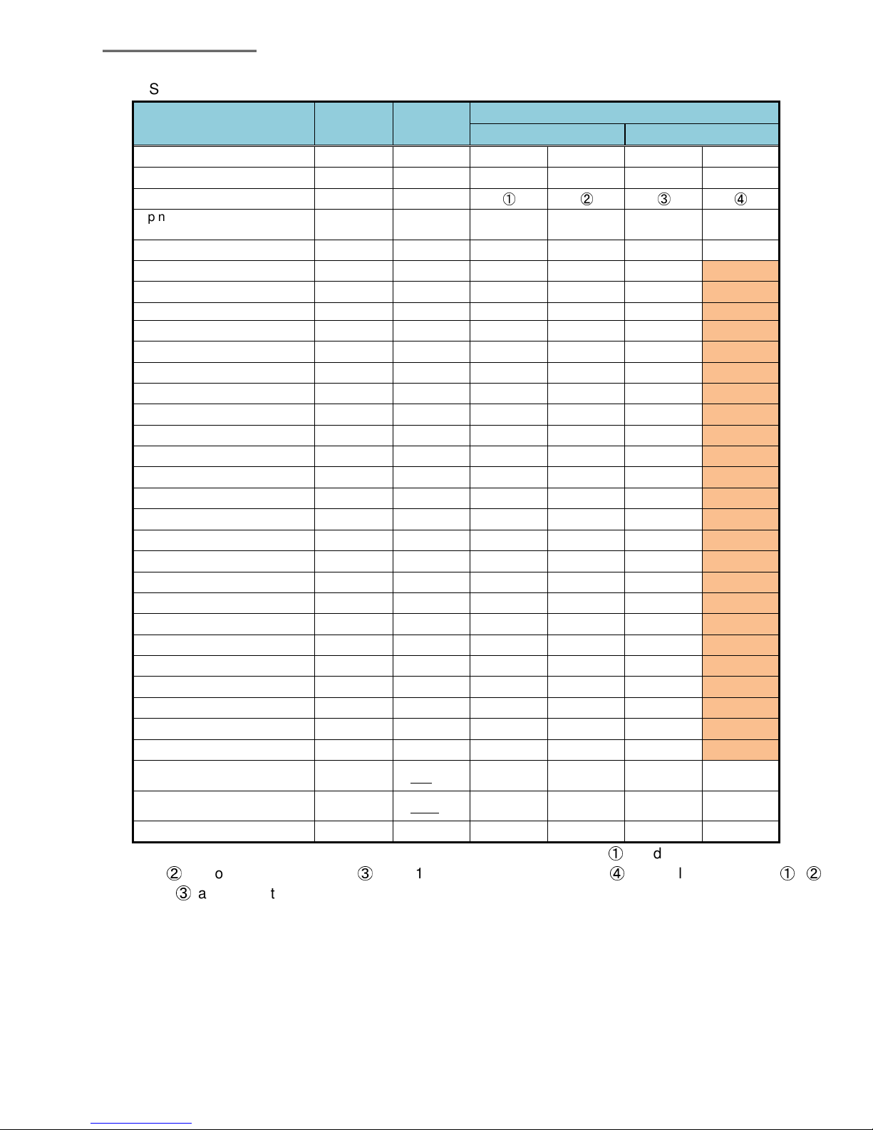
● Spindle Format Output Items (BCD Format)
Output Items
Spindle No. (1 to 32)
PAR No. (1 to 32)
Spindle Judgment*1
Spindle Cycle Count (8
digits)
TOOL Cycle Count (8 digits)
Peak Torque*2
Final Torque*2
Snug Torque*2
1st Peak Torque*2
2nd Peak Torque*2
Final Angle*2
Differential Angle*2 4 -12.3 00 01 23 11
Rate 1*2 4 1.234 00 12 34 03
Rate 1 Increment Torque*2 4 12.34 00 12 34 02
Rate 1 Increment Angle*2 4 123.4 00 12 34 01
Rate 2*2
Rate 2 Increment Torque*2
Rate 2 Increment Angle*2
Rate 3*2
Rate 3 Increment Torque*2
Rate 3 Increment Angle*2
1st Time*2
2nd Time*2
Cycle Time*2
Peak Current*2 4 12.3 00 01 23 01
Angle at Peak Torque*2
Rundown Revolutions*2
ZERO Voltage*2
CAL Voltage*2
Spindle Cycle Count (4
digits)*3
TOOL Cycle Count (4
digits)*3
Load rate 2
Number of
Bytes
2 1
2 2
4
4 123456 00 12 34 56
4 12345678 12 34 56 78
4 12.34 00 12 34 02
4 12.34 00 12 34 02
4 5.67 00 05 67 02
4 12.34 00 12 34 02
4 12.34 00 12 34 02
4 123.4 00 12 34 01
4
4
4
4
4
4
4 123.456 12 34 56 03
4 123.456 12 34 56 03
4 654.321 65 43 21 03
4 123.4 00 12 34 01
4 12.34 00 12 34 02
4 -0.123 00 12 34 13
4 3.512 00 35 12 03
2 123456 01 23 - -
2
Fastening
Data
-0.123 00 01 23 13
12.34 00 12 34 02
123.4 00 12 34 01
0.123 00 01 23 03
12.34 00 12 34 02
123.4 00 12 34 01
12345678 23 45 - -
20 00 20
LSB (1word) MSB (2 word)
00 01
00 02
①
Spindle format
②
③
- -
- -
④
*1: In regard to the Spindle Judgment, “Judgment Data 1” is output as ①, “Judgment Data 2” is output
as ②, “Error Data” is output as ③, and “1st Reject Item” is output as ④. The values output as ①, ②,
and ③ are respectively set by bit allocation from “Fieldbus Message Setting” of the AFC3000 User
Console.
Note: shaded area described on next page
PAGE 15
Page 16
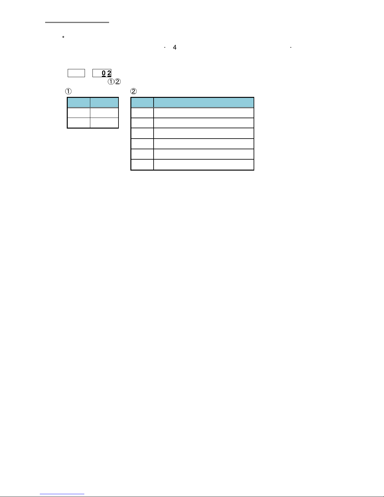
*2: With each of the output items (besides “Spindle No.,” “Parameter No.,” “Spindle Judgment,”
“Spindle Cycle Count (8 digits • 4 digits),” “Tool Cycle Count (8 digits • 4 digits),” and “Load
rate”), the results are output in the order of: indication up to a maximum of 6 digits (without the
decimal point) in 2 words (4 bytes), sign, and number of digits to the right of the decimal point.
12 34
①
Sign ② Number of Digits to the right of the Decimal Point
56 0 2
①②
Devicenet Fieldbus Expansion Unit
Indication
0
1
*3: With each of “Spindle Cycle Count (4 digits)” and “Tool Cycle Count (4 digits),” numerical values of
the millions, hundred thousands, ten thousands, and thousands places are output as 4-digit BCD
data. Once the cycle count reaches 9,999,999 (99 99BCD), the next number (10,000,000) is output
as (00 00BCD).
Details
+ value
- value
Indication
0
1
2
3
4
5
Details
No digits right of decimal point
1 digit right of the decimal point
2 digits right of the decimal point
3 digits right of the decimal point
4 digits right of the decimal point
5 digits right of the decimal point
PAGE 16
Page 17
]
]
]
]
]
]
]
]
]
]
]
.
.
]
]
]
]
.
]
]
.
]
]
]
]
.
]
] ] ]
]
.
.
.
]
.
]
]
]
Devicenet Fieldbus Expansion Unit
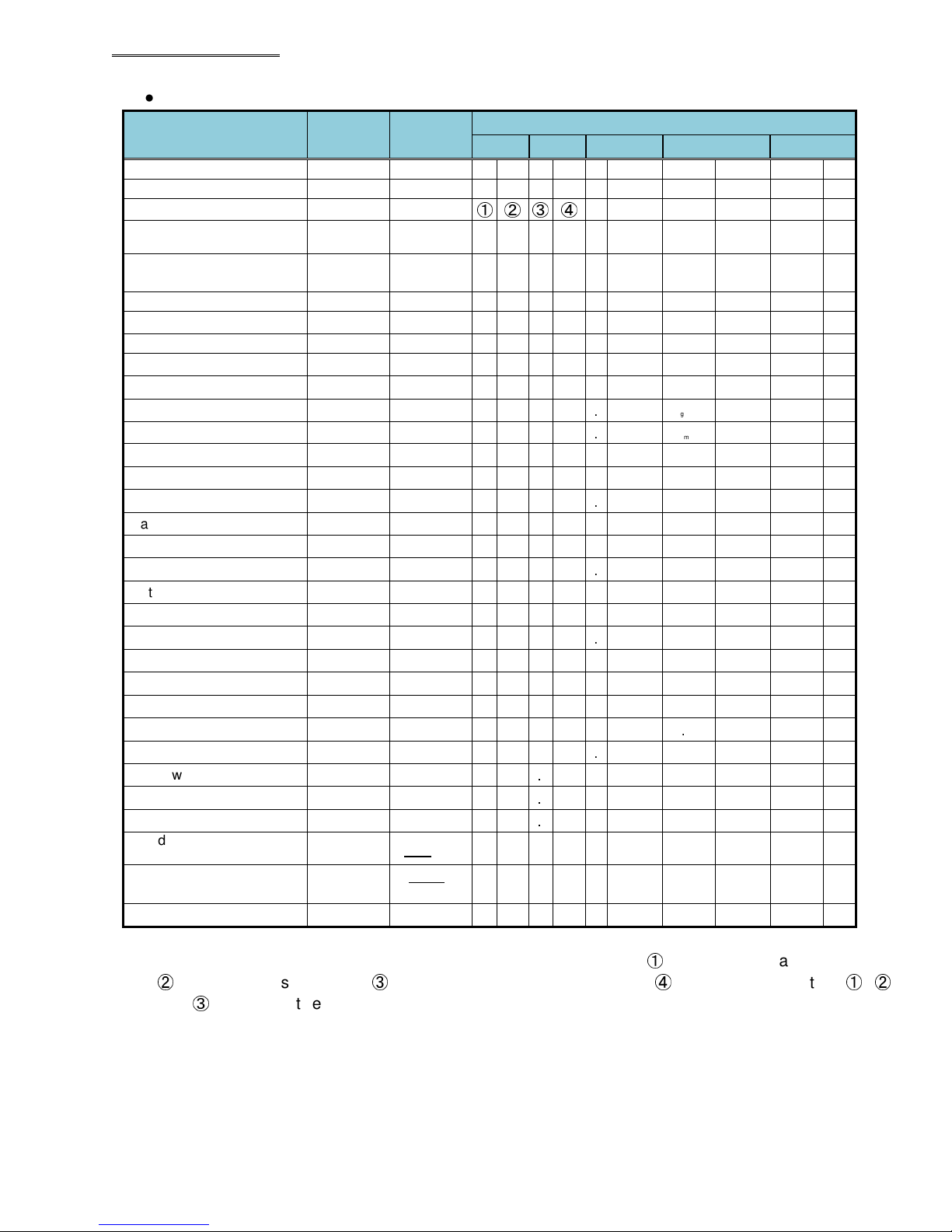
● Spindle Format Output Items (ASCII Format)
Output Items
Spindle No. (1 to 32)*1
PAR No. (1 to 32)
Spindle Judgment*2
Spindle Cycle Count (8
digits)
TOOL Cycle Count (8
digits)
Peak Torque*3
Final Torque*3
Snug Torque*3
1st Peak Torque
2nd Peak Torque
Final Angle*3
Differential Angle*3
Rate 1*3
Rate 1 Increment Torque
Rate 1 Increment Angle
Rate 2*3
Rate 2 Increment Torque
Rate 2 Increment Angle
Rate 3*3
Rate 3 Increment Torque
Rate 3 Increment Angle
1st Time*3
2nd Time*3
Cycle Time*3
Peak Current*3
Angle at Peak Torque
Rundown Revolutions*3
ZERO Voltage
CAL Voltage
Spindle Cycle Count (4
digits)*4
TOOL Cycle Count (4
digits)*4
Load rate
Number
of Bytes
Fastening
Data
2 1
2 2
4
8 123456
8
1234567
8
8 12.34
8 12.34
8 5.67
6 12.34
6 12.34
8 123.4
8 -12.3 -
10 1.234
6 12.34
6 123.4
10 -0.123 -
6 12.34
6 123.4
10 0.123
6 12.34
6 123.4
1 word 2 word 3 word 4 word 5 word
1
2
① ② ③ ④
1 2 3 4 5 6
1 2 3 4 5 6 7 8
1 2 . 3 4
1 2 . 3 4
5 . 6 7
1 2 . 3 4
1 2 . 3 4
1 2 3
]
1 2
1 . 2 3 4
1 2 . 3 4
1 2 3
]
0 . 1 2 3
1 2 . 3 4
1 2 3
0 . 1 2 3
1 2 . 3 4
1 2 3
Spindle format
4
3
4
4
4
10 123.456 1 2 3 . 4 5 6
10 123.456 1 2 3 . 4 5 6
8 654.321 6 5 4 . 3 2 1
10 12.3
6 123.4
8 12.34 1 2
6 -0.123 - 0
6 3.512
4 123456
4
1234567
8
2 3 4 5
4 20
1 2 3
3
1 2 3
2 0
1 2
4
3 4
Judgment Occurrence
1 2 3
5 1 2
Judgment Occurrence
Judgment Occurrence
Judgment Occurrence
Judgment Occurrence
Judgment Occurrence
Judgment Occurrence
Judgment Occurrence
Judgment Occurrence
Judgment Occurrence
Judgment Occurrence
]
.
3
]
]
]
]
]
]
Warning
]
*1: (20H) is the space code (space).
*2: In regard to the Spindle Judgment, “Judgment Data 1” is output as ①, “Judgment Data 2” is output as
②
, “Error Data” is output as ③, and “1st Reject Item” is output as ④. The values output as ①, ②,
and ③ are respectively set by bit allocation from “Fieldbus Message Setting” of the AFC3000 User
Console.
PAGE 17
Page 18
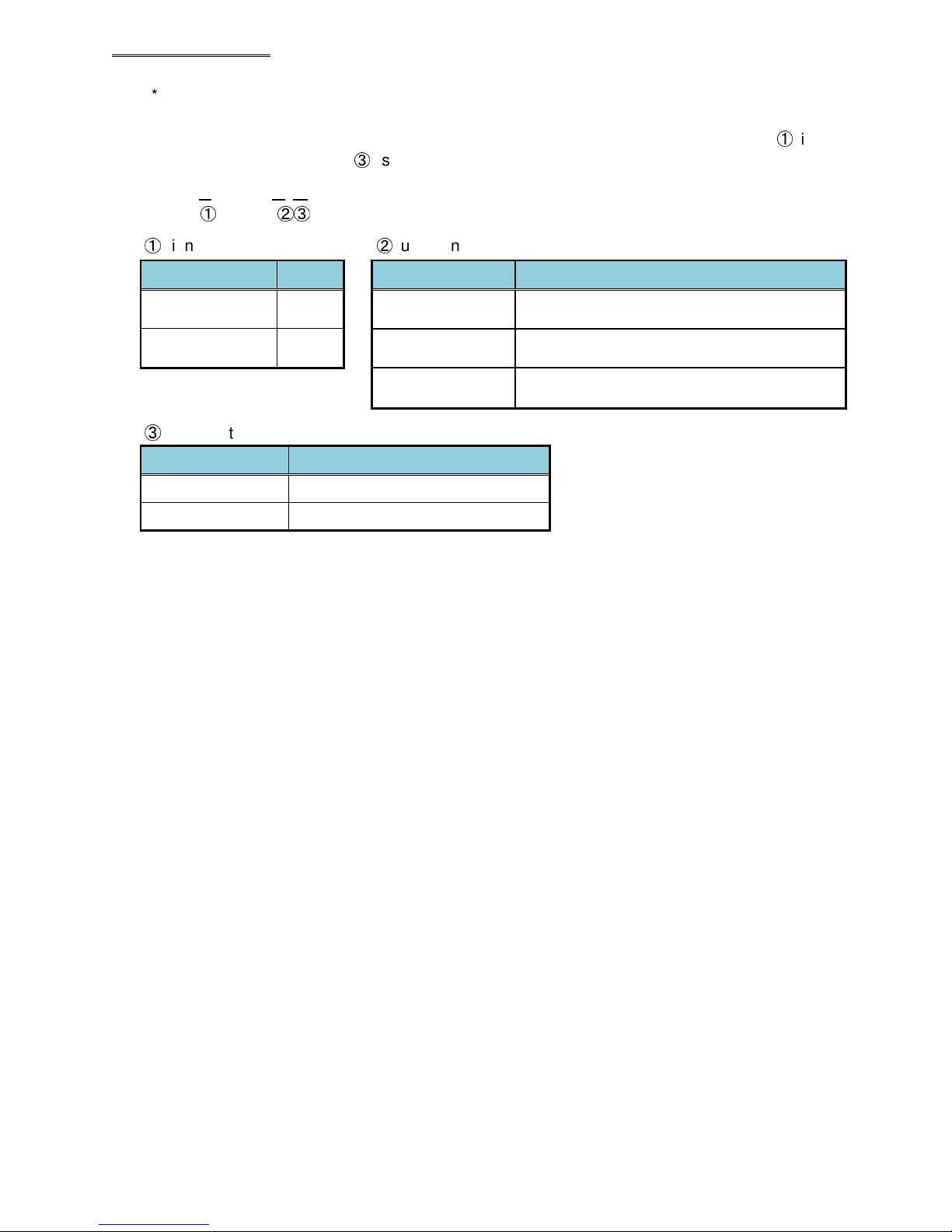
Reject
*3: With each of the output items for which there are set values of high and low limits, the results are
output in the order of: sign, result indication (including the decimal point), judgment code, and 1st
Reject (failure) item. Also with items besides the differential angle and rates 1 to 3, ① is not output,
and for the peak current, ③ is not output.
‘‘‘‘---- 123.5
123.5LLLL XXXX’’’’
123.5123.5
①
①
Sign
Devicenet Fieldbus Expansion Unit
②③
②
Judgment Code
Indication Details
Space (20H) + value
- (2DH) - value
③
1st Reject Item
Indication Details
X (58H) 1st Reject item
Space (20H) Reject item besides the 1st
*4: With each of “Spindle Cycle Count (4 digits)” and “Tool Cycle Count (4 digits),” numerical values of
the millions, hundred thousands, ten thousands, and thousands places are output as 4-digit BCD
data. Once the cycle count reaches 9,999,999 (99 99BCD), the next number (10,000,000) is output
as (00 00BCD).
Space (20H)
Indication Details
Within high and low limit, no warning (peak
current)
H (48H)
L (4CH)
Outside high limit, high limit warning (peak
current)
Outside low limit, low limit warning (peak
current)
PAGE 18
Page 19
Devicenet Fieldbus Expansion Unit
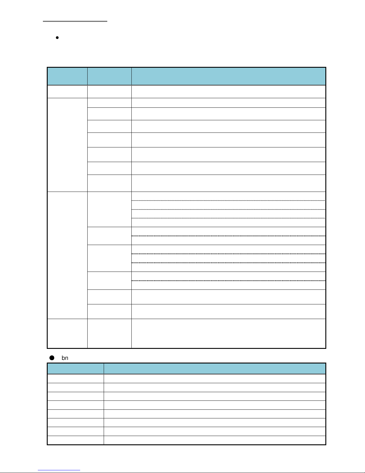
● Judgment Data 1 and 2 Items (in common with BCD and ASCII)
The Judgment data and the Abnormal data of the operation results are set by bit allocation. In regard
to the setting method, please refer to “Fieldbus Message Setting” in the <<AFC3000 User Console
Instruction Manual>>.
Classification
Logic -
Spindle
Judgment
Fastening
Reject Items
Item Details
Message information to be output by a combination of OR and AND is set.
REJECT This is output when a fastening result falls outside a judgment range.
ACCEPT
ABNORMAL
BYPASS
STOP
RESET STOP
START OFF
Torque Reject
Angle Reject
Rate Reject
Time Reject
Rundown
Revolutions
Current Value
Warnings
This is output when fastening ends with the fastening results being within the
judgment ranges.
This is output when an error occurs in the system or during the fastening
operation.
This is output when the BYPASS signal is set to “ON” at the start of fastening
or during the fastening process.
This is output when the STOP signal is set to “OFF” at the start of fastening or
during the fastening process.
This is output when the RESET signal is set to “ON” at the start of fastening or
during the fastening process.
This is output when the START signal is set to “OFF” during the fastening
operation with “Deadman” being set as the start method in the sequence setup.
Peak torque low limit Reject/peak torque high limit Reject
Final torque low limit Reject/final torque high limit Reject
Snug torque high limit Reject
Start torque inhibit high limit Reject
Final angle low limit Reject/final angle high limit Reject
Differential - angle Reject/Differential + angle Reject
Rate 1 low limit Reject/Rate 1 high limit Reject
Rate 2 low limit Reject/Rate 2 high limit Reject
Rate 3 low limit Reject/Rate 3 high limit Reject
1st time low limit Reject/1st time high limit Reject
2nd time low limit Reject/2nd time high limit Reject
Rundown revolution high limit Reject/rundown revolution low limit Reject
Low current value limit warning/high current value limit warning
Auxiliary
Information
Signal
●
Abnormal Data Items (in common with BCD and ASCII)
Abnormal State No.
Abnormal State 1
Judgment
Combination
Bits 1 to 8
Torque transducer error
Abnormal State 3 Preamplifier error
Abnormal State 4 System memory error
Abnormal State 5
Servo apply error
Abnormal State 6 Servo type error
Abnormal State 8 Servo amplifier error
Abnormal State 9
Abnormal State 10
Setting data error
Multi signal error
Allows the configuration of multiple REJECT items to be combined onto single
outputs (8 combination outputs available). The configuration of these signals is
set using the AFC3000 Software (Fieldbus Message Setup Screen).
Details
PAGE 19
Page 20
Devicenet Fieldbus Expansion Unit
● 1st Reject (Failure) Item (in common with BCD and ASCII)
Identifies the reason or cause for a fastening that is stopped / interrupted BEFORE reaching the target
torque (or angle) due to a Reject (outside of the programmed limits). (Some programmed limits can cause
the fastening process to stop due to a Reject prior to fastening completion)
Example: A cycle run with a missing fastener will cause a ‘1ST Time High Limit Reject’. A fastener that
reached the Final Angle High Limit setting before reaching Standard Torque will cause a ‘Final Angle High
Limit reject’.
Note: If the fastening reaches the end of the fastening cycle and rejects, no data will be reported in
this data item.
The BCD output format data is shown below for each type of reject item.
Item Output Format (BCD Format)
No REJECT
Peak torque high limit REJECT
Final torque high limit REJECT
Final angle high limit REJECT
Rate 1 high limit REJECT
Rate 1 low limit REJECT
Rate 2 high limit REJECT
Rate 2 low limit REJECT
Rate 3 high limit REJECT
Rate 3 low limit REJECT
1st time high limit REJECT
2nd time high limit REJECT
Rundown revolution high limit
REJECT
Snug torque high limit REJECT
Start torque inhibit high limit
REJECT
00
01
03
05
09
10
11
12
13
14
15
17
19
21
22
PAGE 20
Page 21
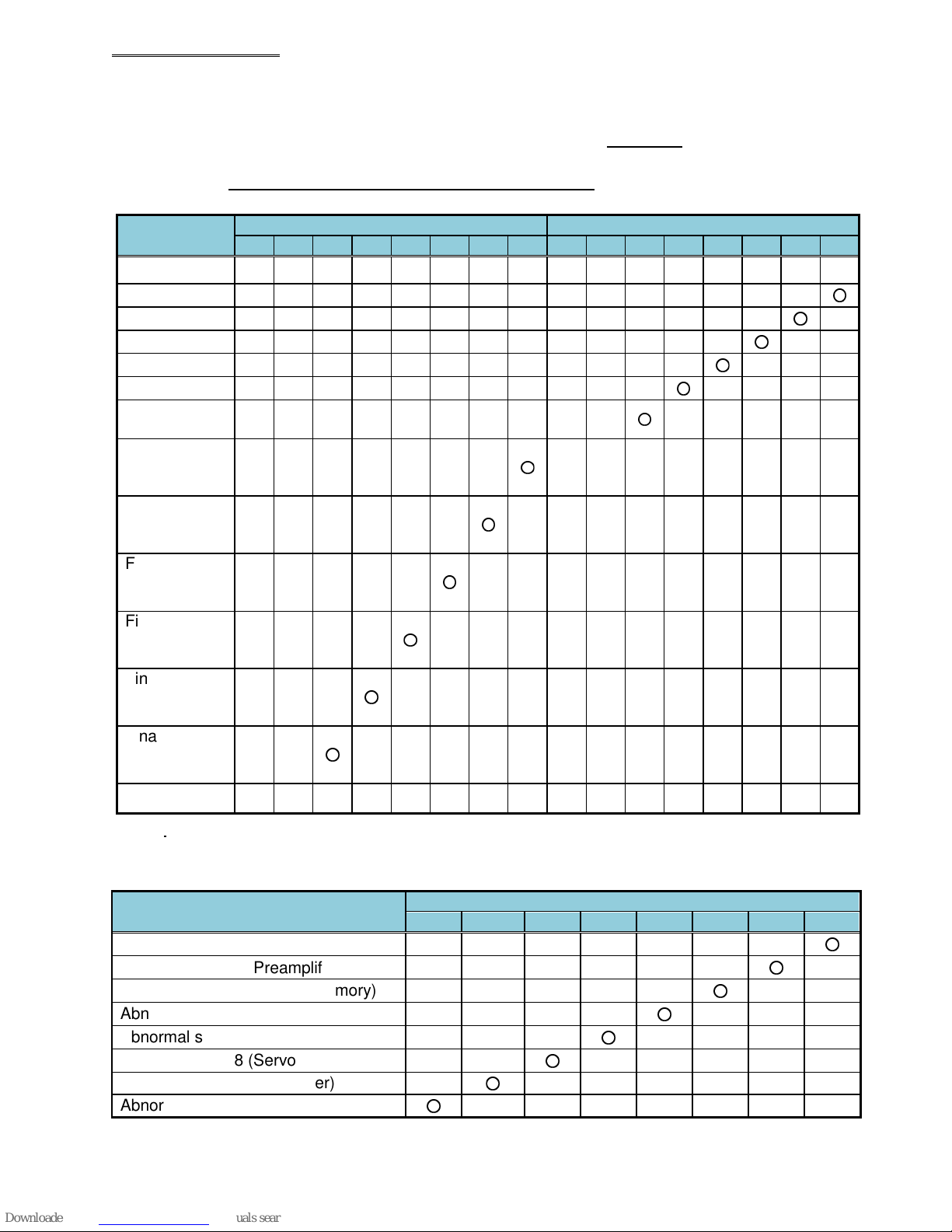
● Fastening Judgment Data Output Items: Example of Spindle Judgment Output Data 1 & 2 (common with
BCD and ASCII format)
The spindle fastening judgment (from a performed fastening cycle) is set by bit allocation of these 2
data bytes. These judgment status bits are set at the end of a completed fastening cycle.
Note: Actual Bit configuration is set using the AFC3000 software in the ‘Fieldbus Message Setup’
screen – Actual bit placement may differ than what is shown.
⋅ Judgment data setting (example from AFC3000 software)
Item
Logic
ACCEPT
REJECT
ABNORMAL
BYPASS
STOP
RESET
STOP
Peak Torque
High Limit
REJECT
Peak Torque
Low Limit
REJECT
Final Torque
High Limit
REJECT
Final Torque
Low Limit
REJECT
Final Angle
High Limit
REJECT
Final Angle
Low Limit
REJECT
~
Devicenet Fieldbus Expansion Unit
Judgment Data 2 (BIT) Judgment Data 1 (BIT)
7 6 5 4 3 2 1 0 7 6 5 4 3 2 1 0
OR OR OR OR OR OR OR OR OR OR OR OR OR OR OR OR
○
○
○
○
○
○
○
○
○
○
○
○
・
Error (Abnormal) Data Setting
The error data (Abnormal reason) of Spindle judgment is set by bit allocation of 1 byte. The data
corresponds to the abnormal state No. when an abnormal condition occurs.
Item
Abnormal state 1 (Torque Transducer)
Abnormal state 3 (Preamplifier)
Abnormal state 4 (System Memory)
Abnormal state 5 (Servo Amp Reply)
Abnormal state 6 (Servo Type)
Abnormal state 8 (Servo Amp)
Abnormal state 9 (Parameter)
Abnormal state 10 (Multi Signal)
Error (Abnormal) Data BIT
7 6 5 4 3 2 1 0
○
○
○
○
○
○
○
○
PAGE 21
Page 22
Format
Spindle
Devicenet Fieldbus Expansion Unit
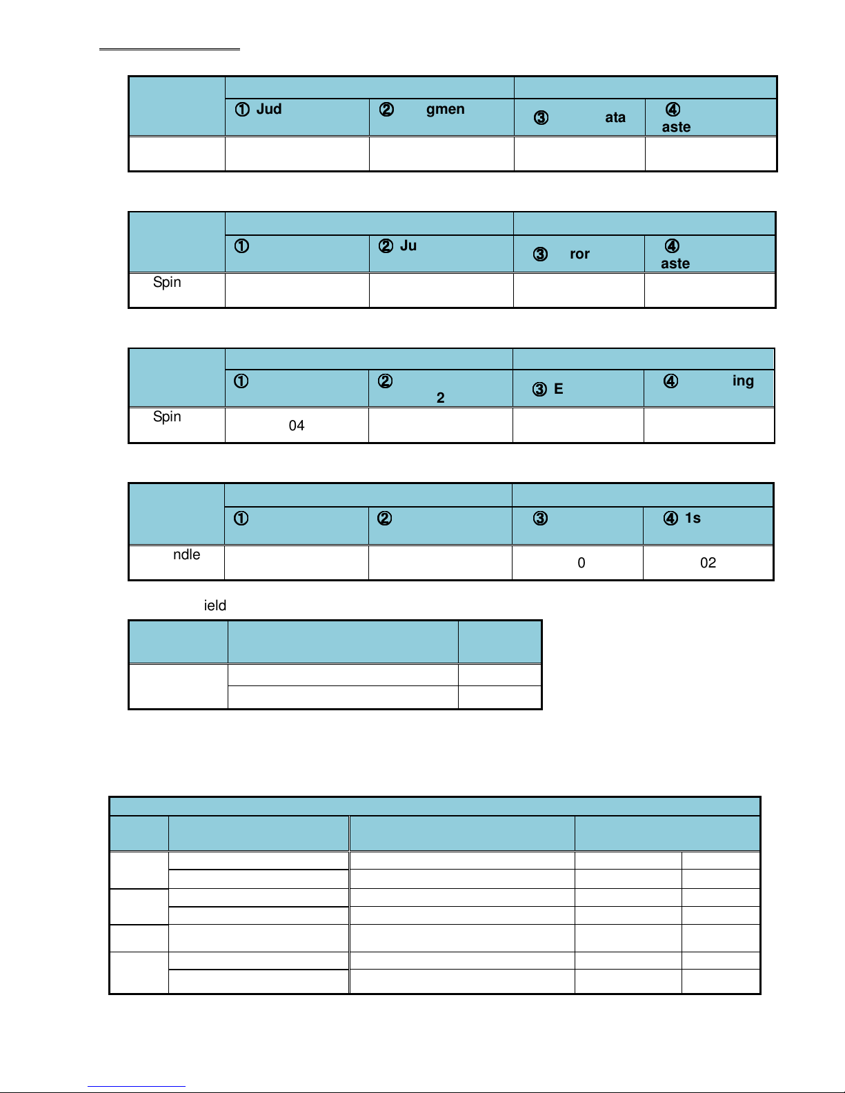
● Example 1: Spindle judgment is “ACCEPT” (Using setup of Judgment data from previous page)
1word 2word
Output Item
Spindle
Judgment
①①①①
Judgment Data
1
01 00 00 00
②②②②
Judgment Data
2
③③③③
Error Data
④④④④
Occurring
Fastening Reject
● Example 2: Spindle judgment is “REJECT”: “Final Torque Low Limit Reject”
1word 2word
Output Item
Spindle
Judgment
①①①①
Judgment Data
1
02 08 00 04
②②②②
Judgment Data
2
③③③③
Error Data
④④④④
Occurring
Fastening Reject
● Example 3: Spindle judgment is “ABN3-3”
1word 2word
Output Item
Spindle
Judgment
①①①①
Judgment Data
1
04 00 02 00
②②②②
Judgment Data
2
③③③③
Error Data
④④④④
Occurring
Fastening Reject
● Example 4: Spindle judgment is “REJECT”: “Peak Torque Low Limit Reject”
1word 2word
Output Item
Spindle
Judgment
①①①①
Judgment Data
1
02 02 00 02
②②②②
Judgment Data
2
③③③③
Abnormal
Data
④④④④
1st Reject
Item
Also, if the fieldbus message is unset, the following contents are output.
Data Format
BCD Format
Output Item
Spindle cycle count (4 digits)
Tool cycle count (4 digits)
Number of
Bytes
2bytes
2bytes
For each of the cycle counts, numerical values of the millions, hundred thousands, ten thousands, and
thousands places are output as 4-digit BCD data. Once the cycle count reaches 9,999,999 (99
99BCD), the next number (10,000,000) is output as (00 00BCD).
● Fieldbus Message Output Example (when not set)
No.
1
2
~
Output Item Result Output PLC Output
Spindle cycle count 1234 C00 00 01
Tool cycle count 12345 C01 00 12
Spindle cycle count 123456 C02 01 23
Tool cycle count 1234567 C03 12 34
~
(Note:PLC output ref. for Allen Bradley)
~
~
~
32
PAGE 22
Tool cycle count 20000678 C063 00 00
Spindle cycle count 12345678 C062 23 45
Page 23
Devicenet Fieldbus Expansion Unit
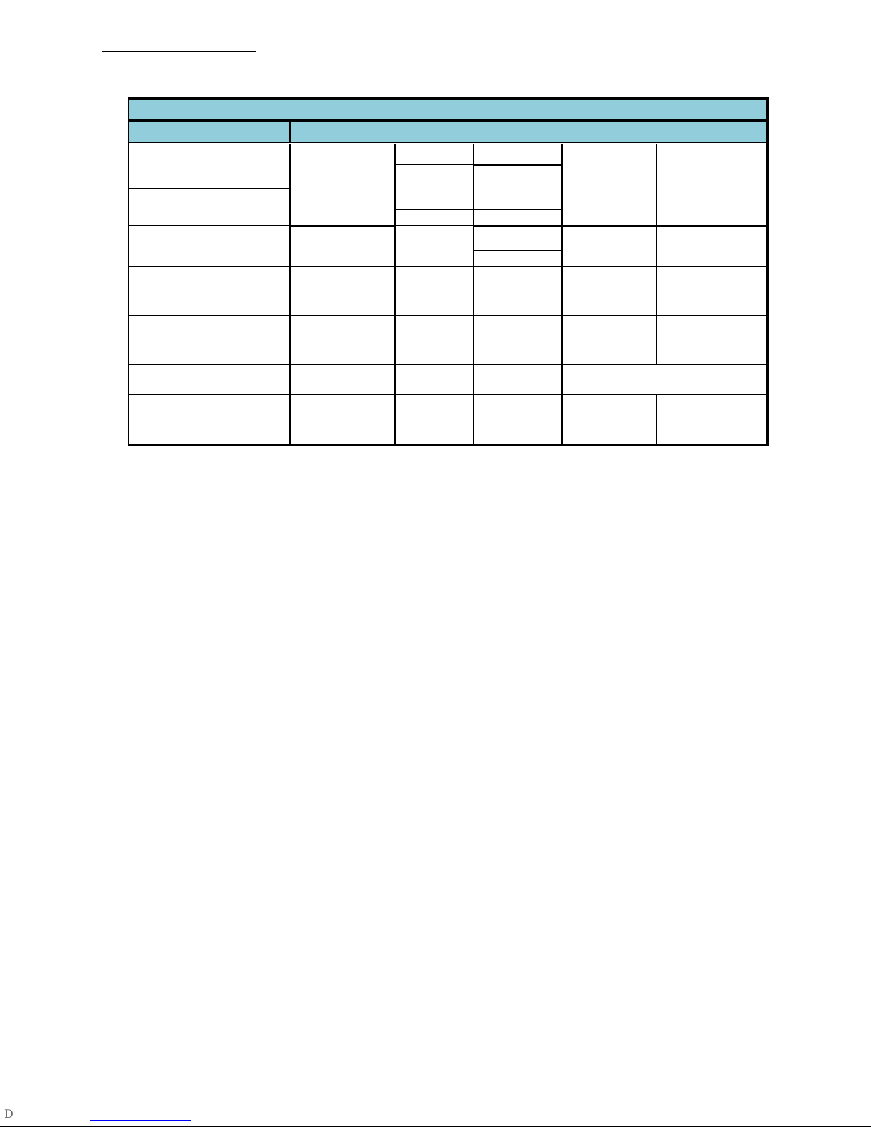
● Message Information Output Example (Multi Format)
Multi Format
Output Item Result Output PLC Input (BCD Format)
Sequence
Cycle Count
Date 2013-06-21
Time 10:23:36
Sequence Judgment REJECT C06 00 01
Sequence No. 1 C07 00 01
216
C00 00 00
C01 02 16
C02 20 13
C03 06 21
C04 10 23
C05 36 00
(Note:PLC output ref. for Allen Bradley)
PLC Input (ASCII Format)
C00 to
C07
C08 to
C17
C18 to
C25
C26 to
C29
C30 to
C31
‘_____216’
‘2013-06-21’
‘10:23:36’
‘REJ_’
‘_1’
~
Final Message Information
Area
(when 250 bytes are set)
~
C124 C124
* (20H) is the space code (space).
~
~
~
PAGE 23
Page 24
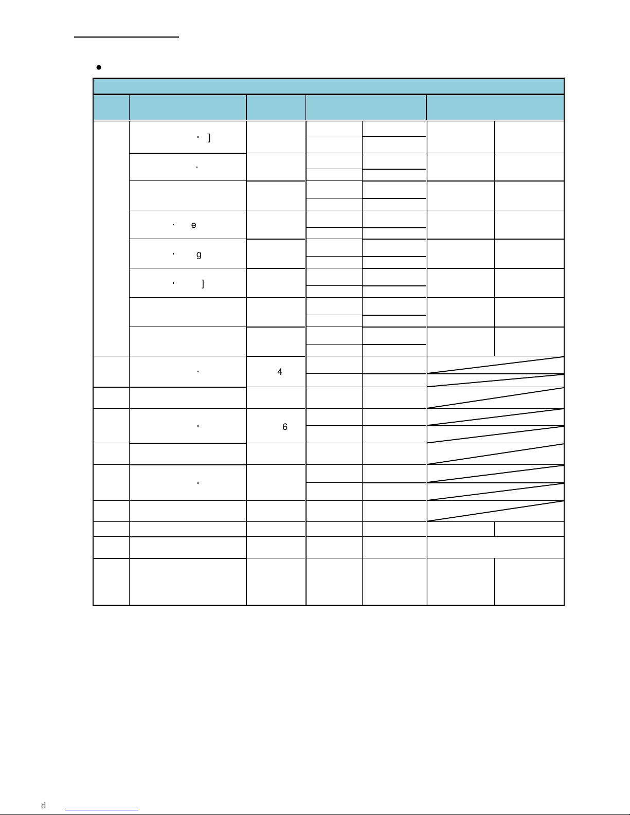
Devicenet Fieldbus Expansion Unit
● Message Information Output Example (Spindle Format)
Spindle Format
Spdl.
No.
1
2
~
Output Item
Peak Torque [N・m]
Final Torque [N・m]
Final Angle [deg] 123.4
Rate 1 [N・m/deg] 1.234
Rate 2 [N・m/deg] 5.678
Rate 3 [N・m/deg] 9.012
1st Time [sec] 12.345
2nd Time [sec] 6.789
Peak Torque [N・m]
~
Result
Output
12.34
12.34
23.45
~
PLC Input (BCD Format)
C00 00 12
C01 34 02
C02 00 12
C03 34 02
C04 00 12
C05 34 01
C06 00 12
C07 34 03
C08 00 56
C09 78 03
C10 00 90
C11 12 03
C12 01 23
C13 45 03
C14 00 67
C15 89 03
C16 00 23
C17 45 02
~
(Note:PLC output ref. for Allen Bradley)
PLC Input (ASCII Format)
C00 to
C07
C08 to
C15
C16 to
C23
C24 to
C33
C34 to
C43
C44 to
C53
C54 to
C63
C64 to
C73
~
‘_123.4HX’
‘__1.234___’
‘__5.678___’
‘__9.012___’
‘_12.345___’
‘__6.789___’
‘_12.34__’
‘_12.34__’
Peak Torque [N・m]
3
~
Peak Torque [N・m]
4
~
Free area C74 C74
~
Final Message Information
Area
(when max 4096 bytes
setup)
~
~
~
* (20H) is the space code (space).
34.56
~
45.67
~
~
C4095 C4095
C32 00 34
C33 56 02
~
C48 00 45
C49 67 02
~
~
~
~
~
~
PAGE 24
Page 25
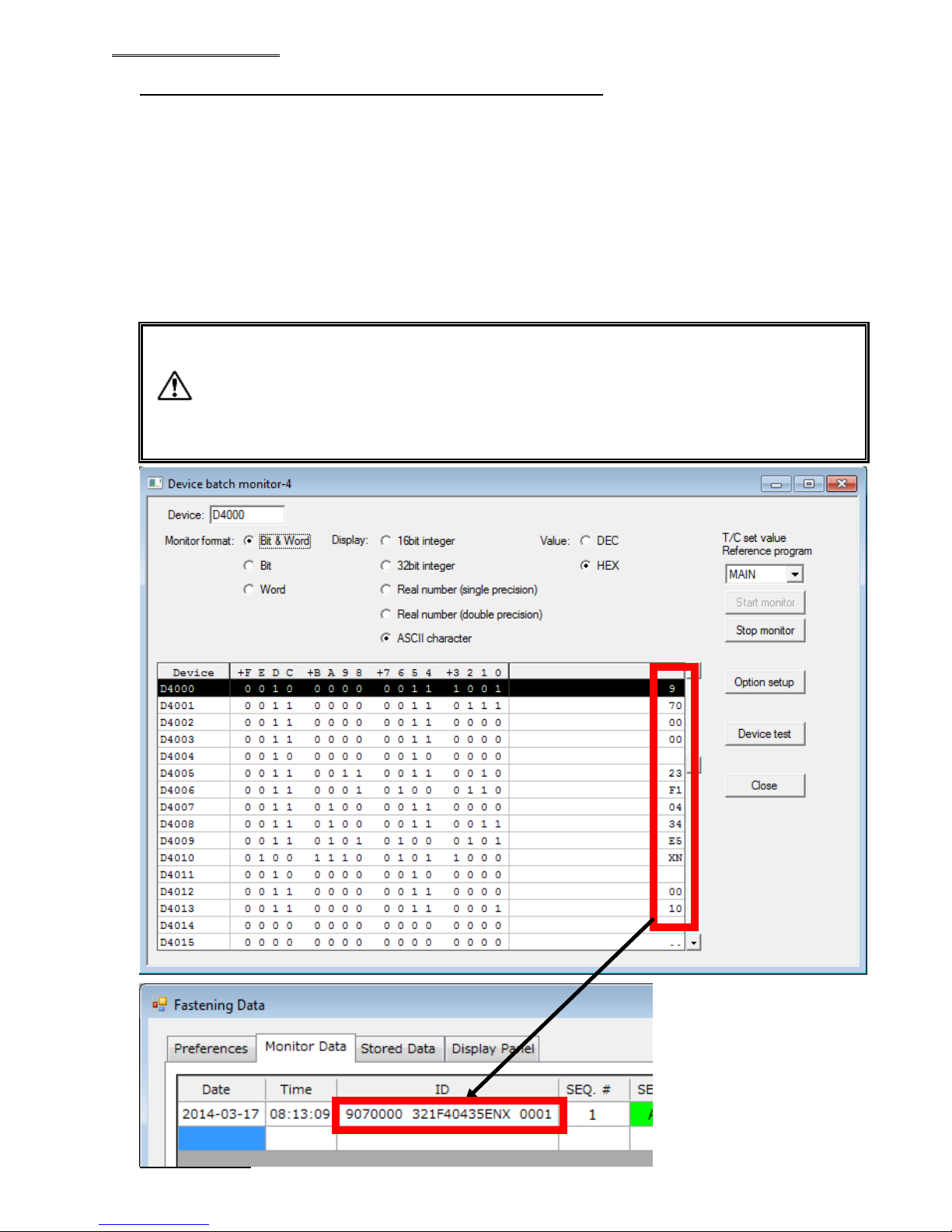
The standard set value
for the ID input data is 32 bytes (16 words). Be care
ful
because even when a value beyond this is set, only the 32 bytes from the start
Devicenet Fieldbus Expansion Unit
Fieldbus Message Setting (PLC →→→→ MASTER Spindle)
1. Contents of Sent Data: ASCII Data
Refer to 3. below regarding the actual sent results.
2. Max. message length: 16words/32 bytes
(As configured in AFC3000 Software)
3. Input Example
Select ASCII letters to send message information from the PLC to the MASTER Spindle for PC
communication and I/O (PLC) control.
The message information sent from the PLC to the MASTER Spindle for PC communication and I/O
(PLC) control is reflected in the fieldbus communication, the AFC3000 User Console, the Unit
RS232C, and the expansion RS232C.
-
are saved in the fastening result retention of the Unit.
Caution
- Do not use the following characters.
“∖∖∖∖”: backslash (yen mark), “/”: slash,
“:”: colon, “*”: asterisk, “?”: question mark,
“””: double quotation, “<” “>”: inequality signs, “|”: pipe sign
PLC configuration
PAGE 25
Page 26
Devicenet Fieldbus Expansion Unit
PLC Setting Example
This procedure is written for using Rockwell Automation RXLogix5000 V15.02.00 and Allen Bradley
CompactLogix L32E. If the system is not the same as listed above, setup may be different. Please
contact to PLC manufacturer for detail as each PLC may be different
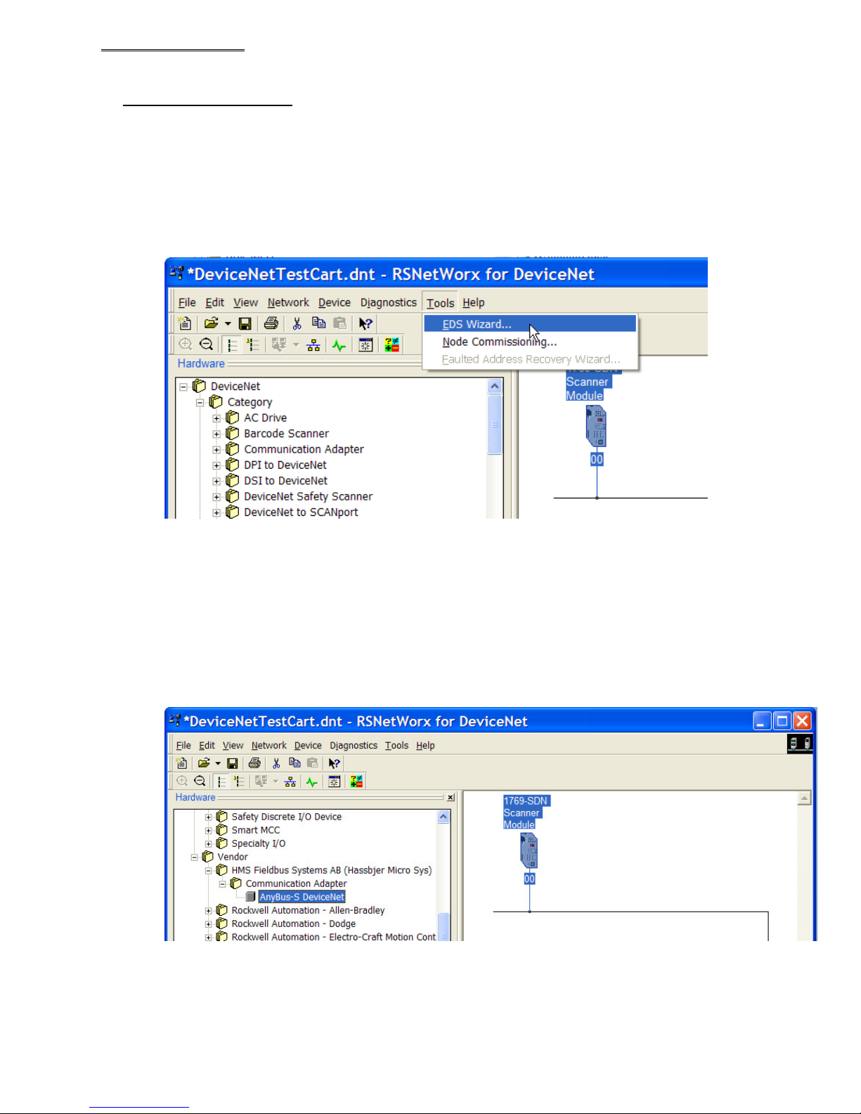
1. Register MASTER Spindle Fieldbus unit to RSNetworks for Devicenet
From the TOOLS menu, select EDS Wizard
Follow the screen for adding EDS file to RSNetWorks for DeviceNet.
The EDS file can be downloaded from our web page @ www.fec-usa.com.
2. Once the EDS file is imported to RSNetWorks, the MASTER Devicenet unit will appear as below:
HMS Fieldbus System AB (Hassbjer Micro Sys)
Communication Adapter
Anybus CompactCom DeviceNet.
PAGE 26
Page 27
AFC3000
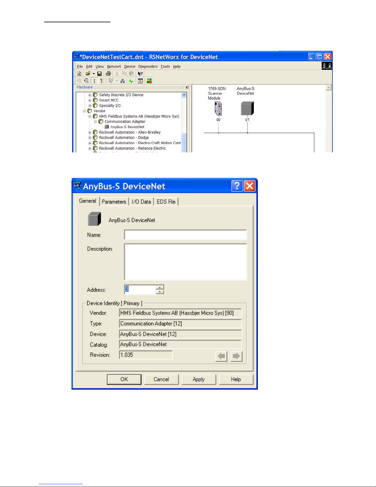
Drag the icon to the DeviceNet connection field. The module will be located on the graphic side
of the display.
Right-Click the module added and select “Properties”.
In the “General” page, edit name and address for system.
Devicenet Fieldbus Expansion Unit
PAGE 27
Page 28
12
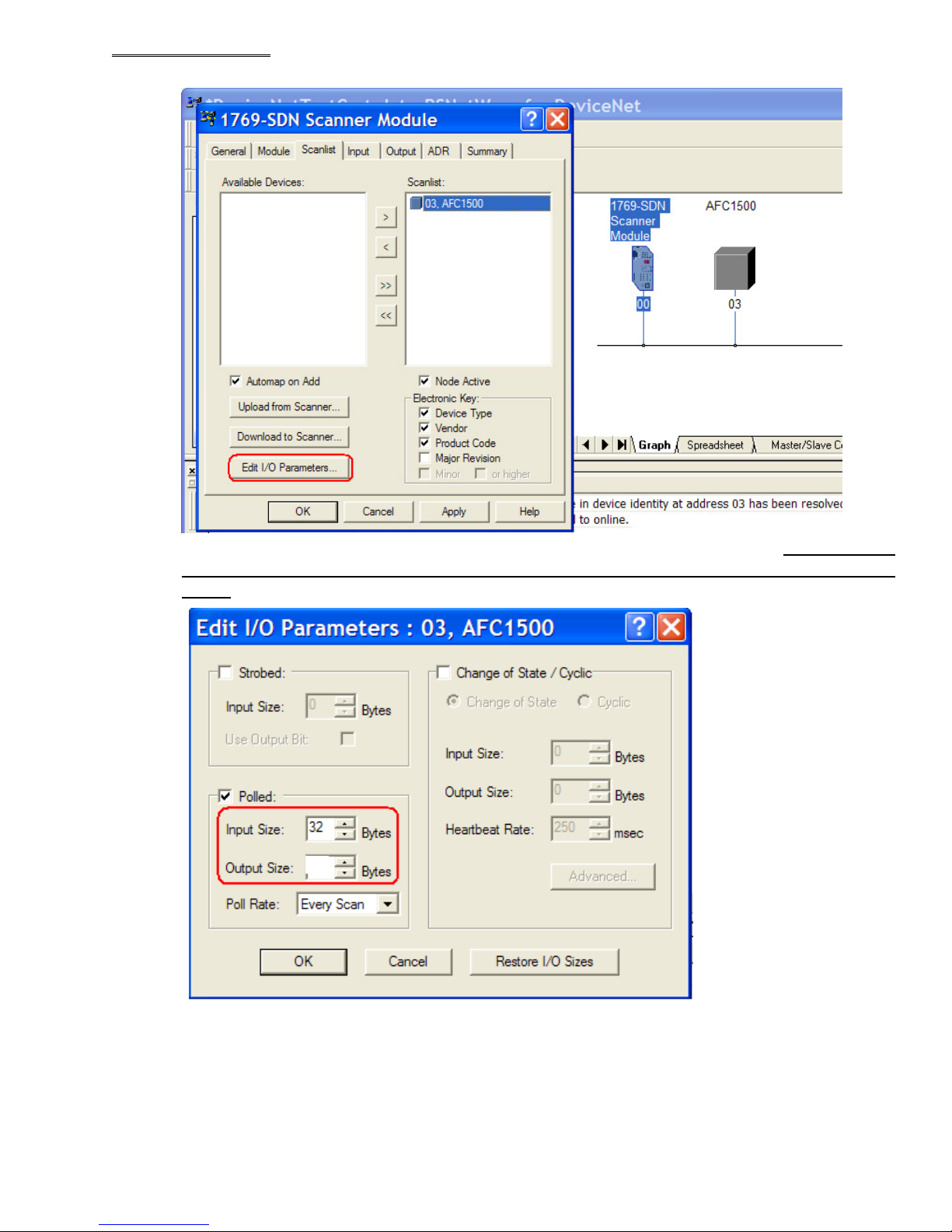
3. Go back to the scanner module properties.
Devicenet Fieldbus Expansion Unit
Using the “Scanlist” tab, select the device to be edited, open the I/O parameters. Make sure the
input size and output size are same as set-up in the Multi Unit Fieldbus set-up performed
earlier.
After the parameter is configured for DeviceNet, download the setup to the PLC.
(The configuration will be stored in the DeviceNet Master memory)
PAGE 28
Page 29
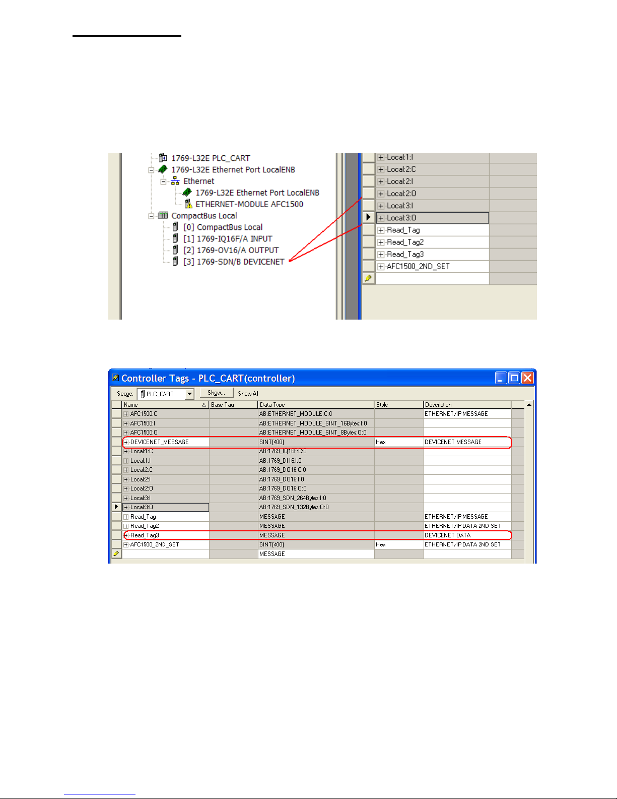
The I/O signals for DeviceNet will be available at Local memory where the DeviceNet Master is
located.
For the message communication, Read Tag and Data buffesr needs to be added to tag table.
Devicenet Fieldbus Expansion Unit
PAGE 29
Page 30
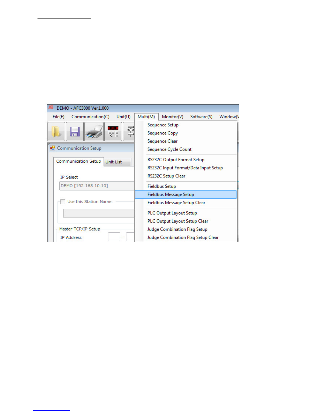
4. Transferring the fastening result data using the MSG function.
For setting up the MESSAGE function, first the AFC3000 needs to be configured for the data type that
needs to be sent to the PLC. Configuration is done in the AFC3000 Userconsole Software. Select
“Field Bus Message Setup” from “Multi” pull down menu.
Devicenet Fieldbus Expansion Unit
Select the DATA TYPE format (BCD or ASCII).
Data from the Master (Multi) and Spindle (Axis) must be configured in the table below each tab. The
Multi format contains the “Header” data (such as Date, Time, Sequence #, Cycle Count, etc. – aka data
that comes from the Master Unit) The Axis format contains the actual spindle fastening data (such as
Torque, Angle, Time, Rate, etc.) Right click on the table and select the item from the pop up window
that you wish to be transferred.
PAGE 30
Page 31
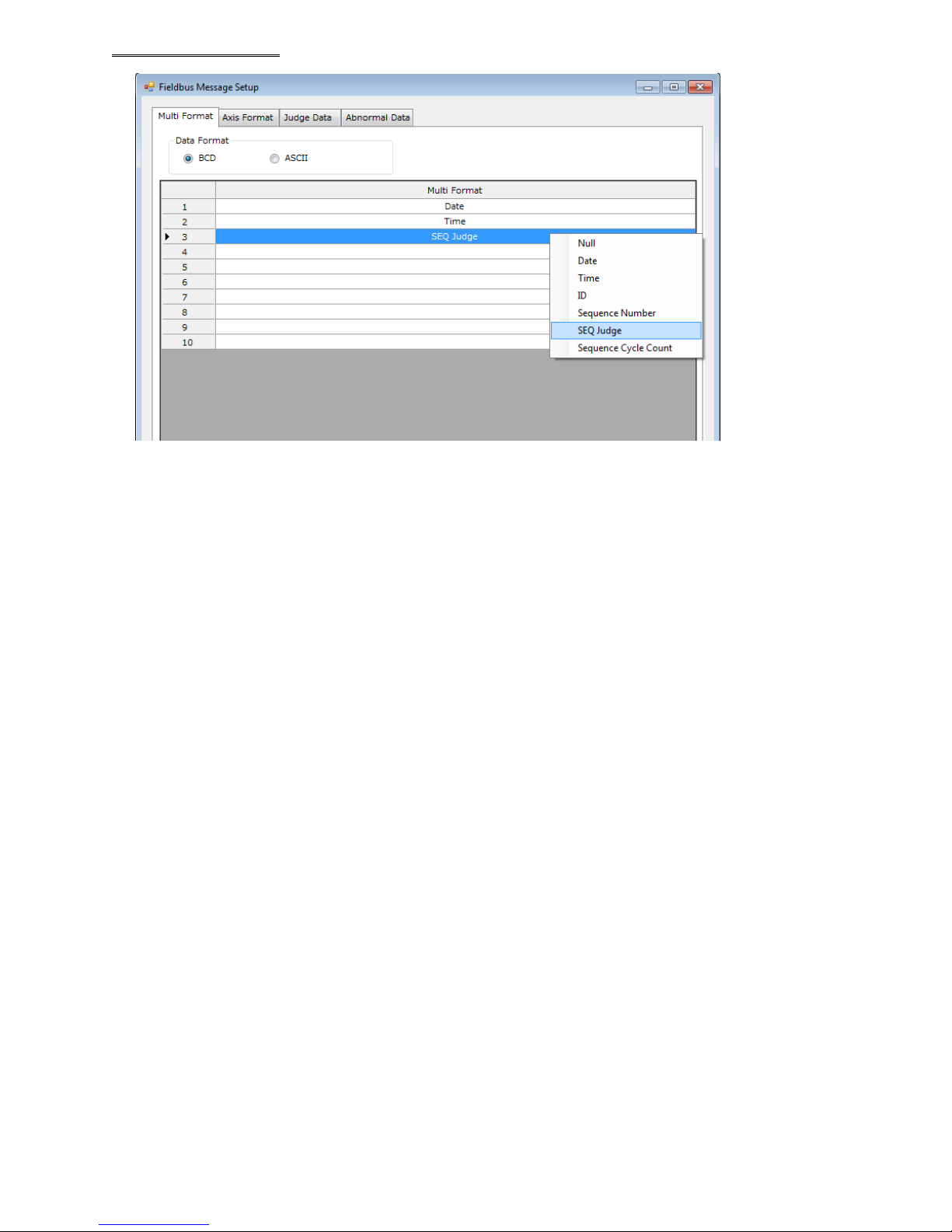
(Example of Multi format selection shown above)
Note: Selecting “Null” deletes the item from the list.
Devicenet Fieldbus Expansion Unit
PAGE 31
Page 32
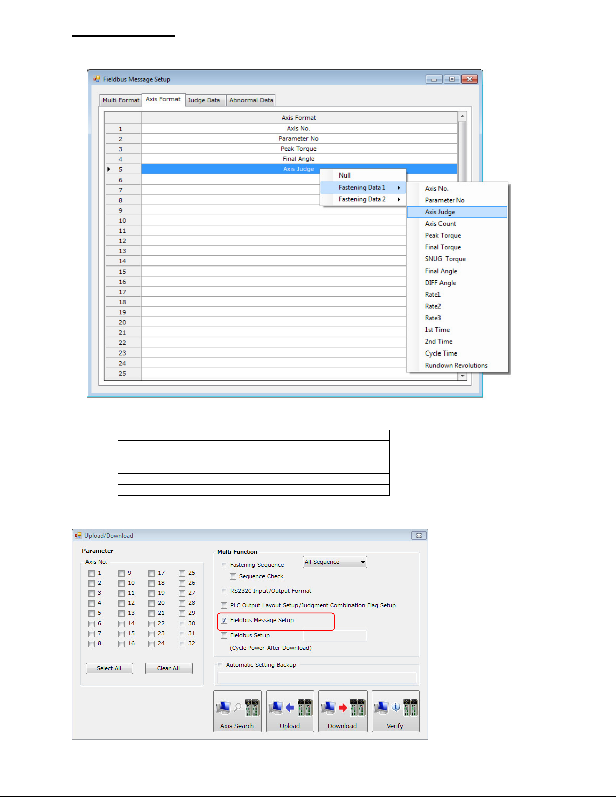
Devicenet Fieldbus Expansion Unit
(Example of Axis format selection shown below – this format will be for EACH spindle connected in the
system to the Master Unit)
When the system has more than 1 spindle, the data will be output in spindle sequential order as shown
below.
Data from total fastening status (Multi data)
Data from SPINDLE 1
Data from SPINDLE 2
Data from SPINDLE 3
|
Data from up to SPINDLE 32
After the fastening result data has been setup, download the changed configuration to the Master controller.
PAGE 32
Page 33
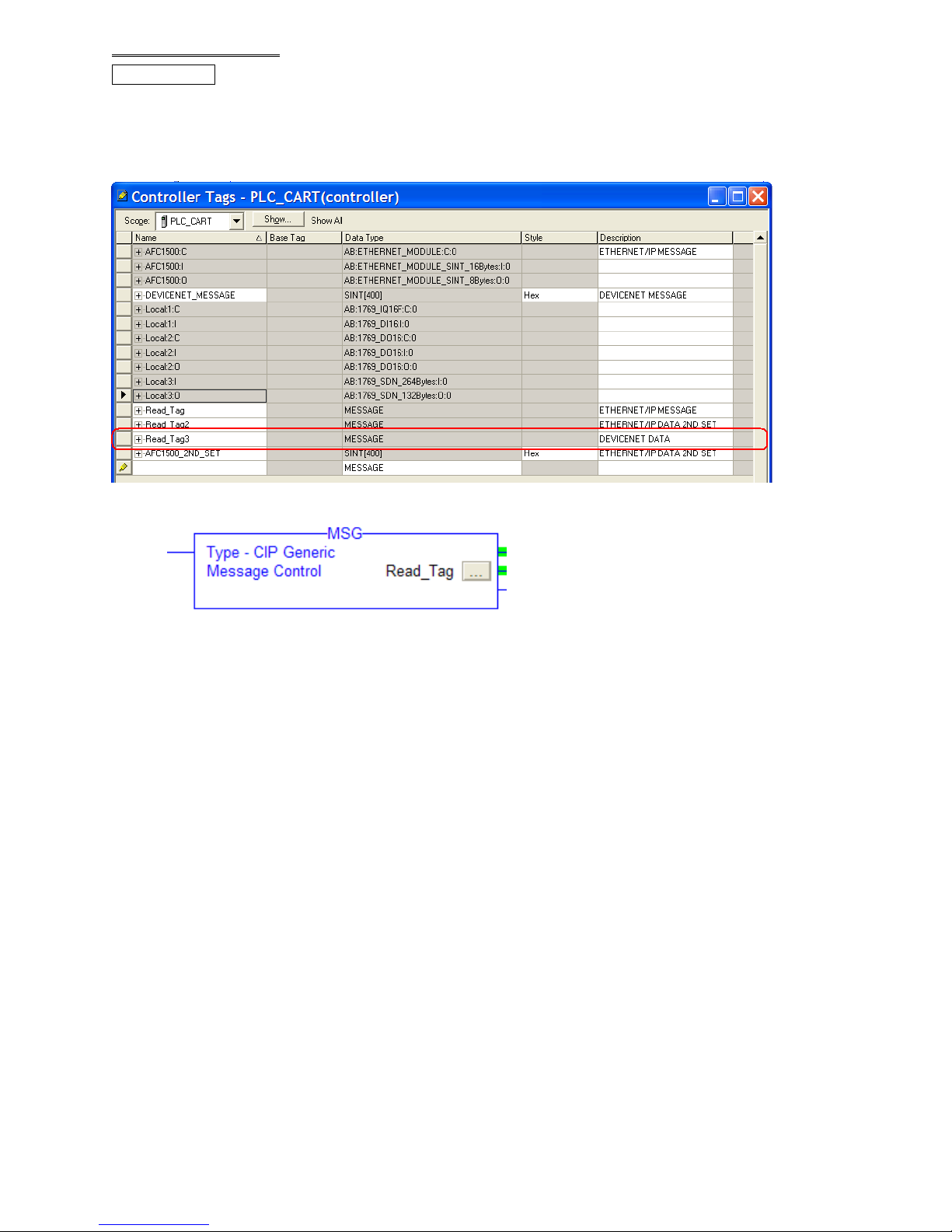
PLC program.
1. Read_Tag needs be added to the “Controller Tags” for message transfer
This data tag contains the configuration of the message transfer.
Each MSG command needs to have its own Read_ tag.
The MSG command is used for transferring the fastening result.
Devicenet Fieldbus Expansion Unit
PAGE 33
Page 34
A2
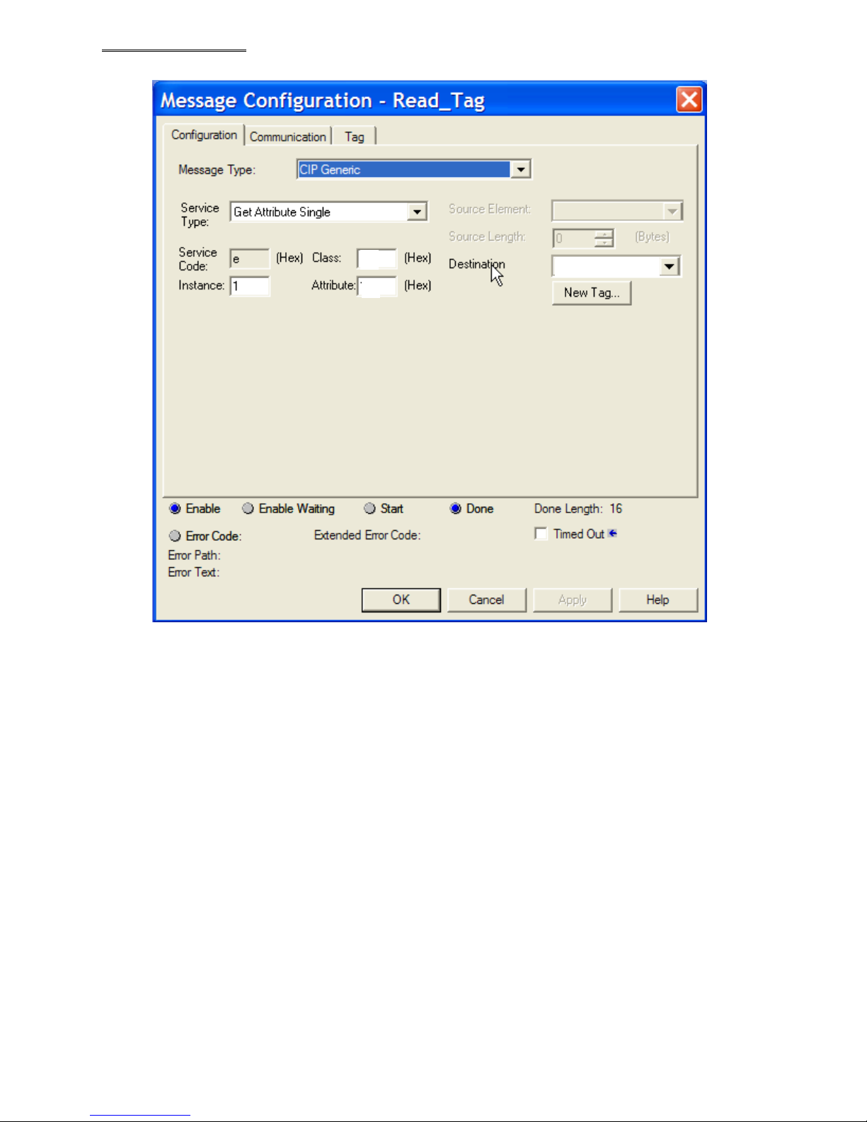
Property of the MSG command is shown below. (Right Click in MSG command)
Devicenet Fieldbus Expansion Unit
DEVICENET_MESS
5
Message Type CIP Generic
Service Type Get Attribute Single
Service Code E
Class A2
Instance 1 ~ 17
Attribute 5
Destination The controller tag added for Devicenet
should be selected
Note: Each message command can only handle 250 bytes. If more than 250 bytes of data needs to
be transferred, another controller tag needs be added (Read_tag) for the buffer and another MSG
command needs be added. The second MSG command should have its “instance” as “2” with its
“Destination” address incremented to the next block of data (250, 500, 750, 1000, etc.) and so on up
to a maximum of 17 for up to 4096 bytes of message data).
Example: [AFC3000:C.Data(250)] for the second block of 250 bytes
PAGE 34
Page 35
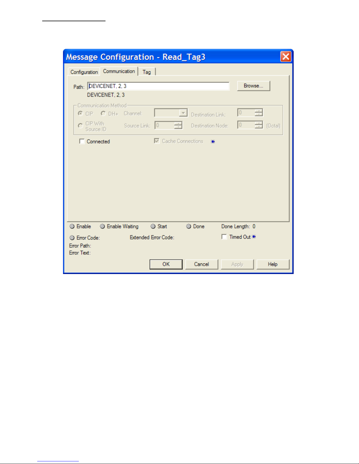
At the communication tab screen, select “Path”. DeviceNet Master module should be selected.
Add “2,3” after that.
Devicenet Fieldbus Expansion Unit
“2” denotes the communication command for message data
“3” describes for AFC1500 DeviceNet Node Address.
PAGE 35
Page 36
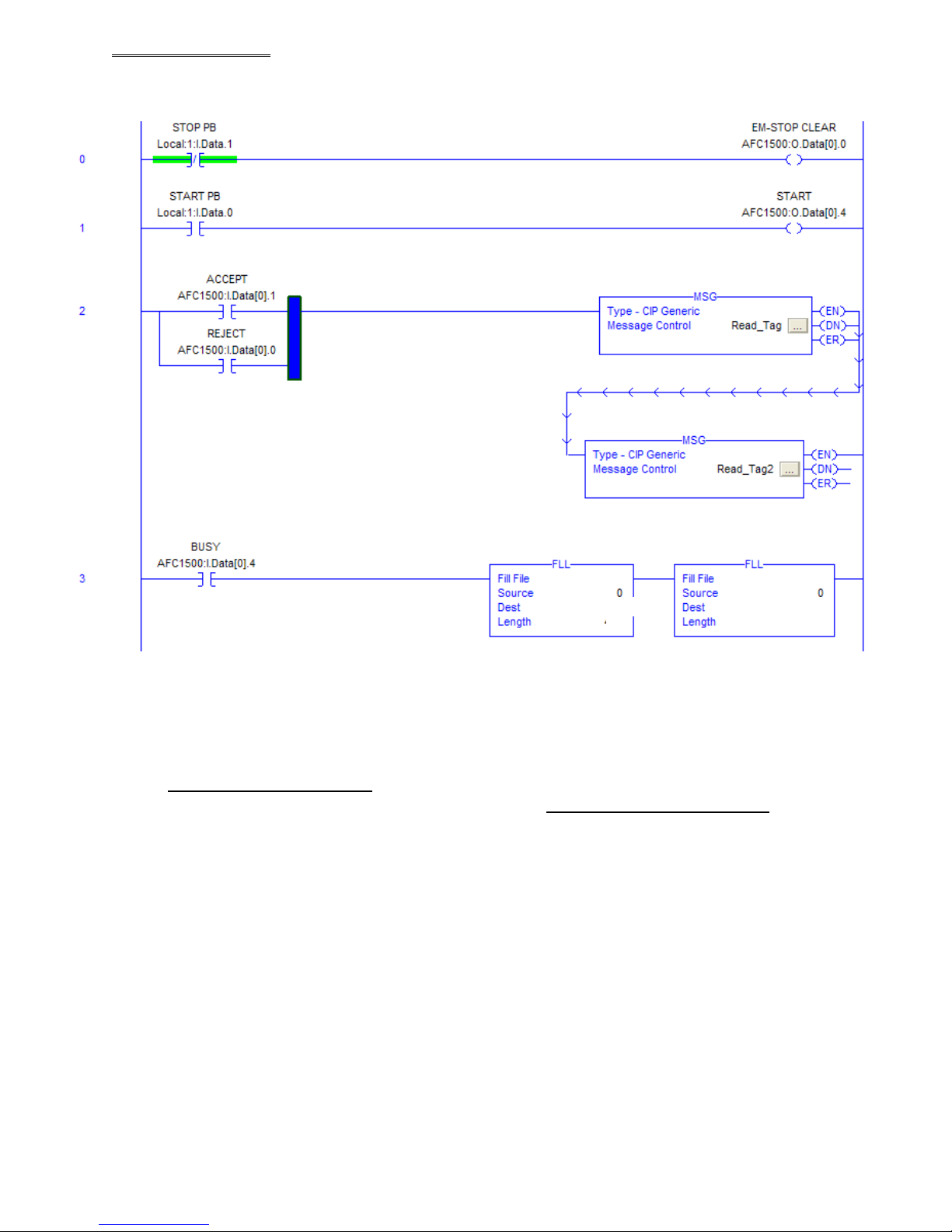
An example of a message transfer PLC program is shown below.
This program transfers up to 250 bytes of fastening result data.
The first MSG command has “1” as “Instance” and is sending the data into
DEVICENET_MESSAGE[0] memory block. The second MSG command has “2” as “Instance” and
sending the data into another data memory block DEVICENET_MESSAGE[250] that would have
been manually added when the second Read_tag was added.
Note: All instructions above that show “AFC1500” would be “AFC3000” for the AFC3000 setup.
Note: The above information contained in this procedure are meant for REFERENCE ONLY when
configuring an FEC Ethernet I/P interface using FEC AFC3000 User Console Software, FEC
AFC3000 Nutrunner System, Rockwell Automation RSlogix 5000 software and Allen Bradley
CompactLogix L32E hardware. Actual application configuration may differ from this set-up depending
on the PLC chosen for the application.
Devicenet Fieldbus Expansion Unit
DEVICENET Message 1ST set
ND
Set
DEVICENET_MESSAGE[250]
DEVICENET Data 1ST set
DEVICENET_MESSAGE[0]
250
DEVICENET Data 2
DEVICENET Data 2
ND
Set
250
PAGE 36
 Loading...