

Page 1
IOM-F-FreezeProtection
FREEZE PROTECTION SERIES 850, LF850, 860 AND LF860 1⁄2" - 2" (15 - 50 mm)
Draining Procedure for Freeze Protection
WARNING
!
You are required to thoroughly read all installation instructions and product
safety information before beginning. FAILURE TO COMPLY WITH PROPER
INSTRUCTIONS COULD RESULT IN PRODUCT FAILURE WHICH CAN
CAUSE PROPERTY DAMAGE AND/OR PERSONAL INJURY.
Local building or plumbing codes may require modifications to the information provided. You are required to consult the local building and plumbing
codes prior to installation. If this information is not consistent with local
building or plumbing codes, the local codes should be followed.
Damage from freezing will be costly. FEBCO products are not warranted
against freeze damage. The following instructions will protect against
freezing of Double Check Assemblies (DC) and Reduced Pressure Zone
Assemblies (RP).
Freeze Protection Guidelines
Backflow prevention assemblies must be protected against freezing for the
winter in areas where freezing temperatures may occur. If the water inside
the assembly freezes, damage to the assembly and the system may occur.
Proper draining, insulation using heat tape and heated protective enclosures
are all acceptable methods of freeze protection. In areas with freezing temperatures the 850U, 860U, LF850U and LF860U with union end ball valves
might be considered. The union end ball valve allows the body of the device
to be removed.
When draining an assembly to prevent freezing, several important points
must be remembered:
1. The assembly cannot be adequately drained though the test cocks. For
proper draining follow the instructions detailed in the Drain Procedure
section.
2. Drain valves must be added on the inlet and outlet sides of the assembly, below the assembly (and preferably below the freeze line if the
remainder of the system is to be drained).
Drain Procedure
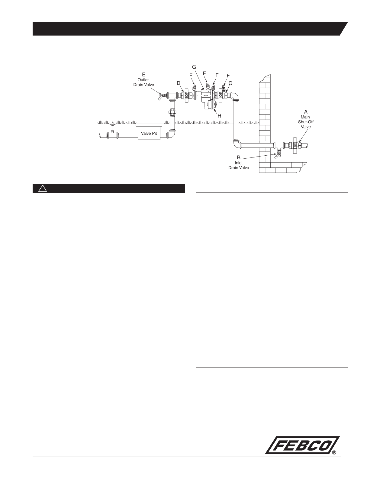
1. Close the main shut-off valve (A).
2. Open the inlet drain valve (B).
3. Open the inlet and outlet ball valves (C & D) 45° (half open, half closed).
4. Open all testcocks (F).
5. Open the outlet drain valve (E).
6. Remove the cover (G) and inlet check module until all water inside valve
drains back out through inlet drain valve (B).
7. If you “blowout” the piping downstream of the backflow assembly using
compressed air:
t$POOFDUUIFBJSTVQQMZUPUIFPVUMFUESBJOWBMWF&BOEDMPTFUIF
outlet ball valve (D).
t"GUFSDMFBSJOHUIFTZTUFNXJUIBJSQBSUJBMMZPQFOUIFPVUMFUCBMMWBMWF
(D).
t-FBWFBMMESBJOWBMWFT&#UFTUDPDLT'BOECBMMWBMWFT$%
in a half open, half closed position for the winter.
(See the ball valve freeze protection instructions for more details.)
t.BLFTVSFUIFNBJOTIVUPGGWBMWF"SFNBJOTDMPTFEBOEEPFTOPU
leak.
8. (RP UNITS ONLY) Loosen the relief valve cover (H) to drain. Tighten
when draining is completed.
Spring "Start-up" Procedure
When there is no more chance of freeze damage:
1. Close all drain valves (E & B), testcocks (F) and ball valves (C & D).
2. Retighten the relief valve cover (H), then slowly open the main shut off
valve (A) and the inlet ball valve (C).
3. Slightly open, and then close, all testcocks (F) one at a time to empty air
from the device.
4. Slowly open the outlet ball valve (D) and refill the system.
Page 2
FREEZE PROTECTION SERIES 850, LF850, 860 AND LF860 1⁄2" - 2" (15 - 50 mm)
Ball Valve Draining Procedure for Freeze Protection
Ball valves should be drained for the winter in areas where freezing temperatures may occur. Water will become trapped between the ball and
valve body if the valve is left in either the full open or full closed position.
If water should freeze between the ball and valve body, damage to the ball
valve will occur.
After draining procedures on the backflow prevention assembly have been
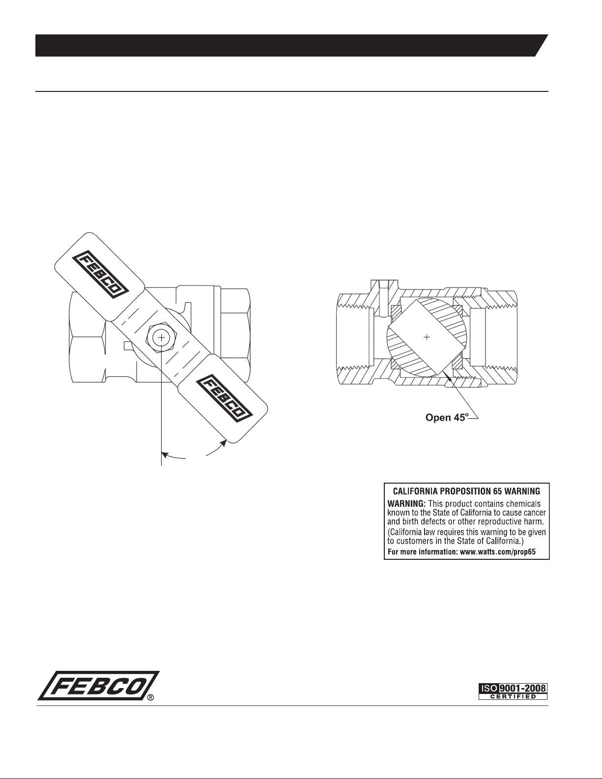
completed, all ball valves must be left in a half open / half closed (45°
degree) position as shown in Figure A. Open the ball valve approximately
45° degrees while draining the pipeline and assembly to allow water
between the ball and valve body to drain as shown in Figure B. Leave the
ball valve in this position for the winter to prevent freeze damage.
The valve must be closed before the system can be repressurized.
NOTE: Open and close ball valves slowly at all times to prevent
damage to the system.
Figure B: Cutaway drawing displaying ball valve in half open/half
closed position
45°
Figure A: Ball Valve in half open/half closed 45° degree position
Limited Warranty: '&#$0UIFi$PNQBOZwXBSSBOUTFBDIQSPEVDUUPCFGSFFGSPNEFGFDUTJONBUFSJBMBOEXPSLNBOTIJQVOEFSOPSNBMVTBHFGPSBQFSJPEPG POFZFBSGSPNUIFEBUFPGPSJHJOBMTIJQNFOU
*OUIFFWFOUPGTVDIEFGFDUTXJUIJOUIFXBSSBOUZQFSJPEUIF$PNQBOZ XJMMBUJUTPQUJPOSFQMBDFPSSFDPOEJUJPOUIFQSPEVDUXJUIPVUDIBSHF
THE WARRANTY SET FORTH HEREIN IS GIVEN EXPRESSLY AND IS THE ONLY WARRANTY GIVEN BY THE COMPANY WITH RESPECT TO THE PRODUCT. THE COMPANY MAKES NO OTHER
WARRANTIES, EXPRESS OR IMPLIED. THE COMPANY HEREBY SPECIFICALLY DISCLAIMS ALL OTHER WARRANTIES, EXPRESS OR IMPLIED, INCLUDING BUT NOT LIMITED TO THE IMPLIED
WARRANTIES OF MERCHANTABILITY AND FITNESS FOR A PARTICULAR PURPOSE.
5IFSFNFEZEFTDSJCFE JOUIFmSTUQBSBHSBQIPGUIJTXBSSBOUZ TIBMMDPOTUJUVUFUIFTPMF BOEFYDMVTJWFSFNFEZGPS CSFBDIPGXBSSBOUZBOEUIF$PNQBOZ TIBMMOPUCFSFTQPOTJCMFGPSBOZJODJEFOUBMTQFDJBM
PSDPOTFRVFOUJBMEBNBHFTJODMVEJOHXJUIPVUMJNJUBUJPOMPTUQSPmUTPSUIFDPTUPGSFQBJSJOHPSSFQMBDJOHPUIFSQSPQFSUZXIJDIJTEBNBHFEJGUIJTQSPEVDUEPFTOPUXPSLQSPQFSMZPUIFSDPTUTSFTVMUJOHGSPN
MBCPSDIBSHFTEFMBZTWBOEBMJTNOFHMJHFODFGPVMJOHDBVTFECZ GPSFJHONBUFSJBMEBNBHFGSPNBEWFSTFXBUFSDPOEJUJPOTDIFNJDBMPSBOZPUIFSDJSDVNTUBODFTPWFSXIJDIUIF$PNQBOZIBTOPDPOUSPM
5IJTXBSSBOUZTIBMMCFJOWBMJEBUFECZBOZBCVTFNJTVTFNJTBQQMJDBUJPOJNQSPQFSJOTUBMMBUJPOPSJNQSPQFSNBJOUFOBODFPSBMUFSBUJPOPGUIF QSPEVDU
4PNF4UBUFTEP OPUBMMPXMJNJUBUJPOTPOIPXMPOHBOJNQMJFEXBSSBOUZ MBTUTBOE TPNF4UBUFTEPOPUBMMPX UIFFYDMVTJPOPSMJNJUBUJPOPGJODJEFOUBMPSDPOTFRVFOUJBMEBNBHFT5IFSFGPSFUIF BCPWF
MJNJUBUJPOTNBZ OPU BQQMZ UPZPV5IJT -JNJUFE 8BSSBOUZ HJWFTZPVTQFDJmDMFHBMSJHIUTBOE ZPVNBZIBWFPUIFSSJHIUT UIBU WBSZ GSPN 4UBUFUP4UBUF:PVTIPVMEDPOTVMUBQQMJDBCMF TUBUF MBXT UP
EFUFSNJOFZPVS SJHIUTSO FAR AS IS CONSISTENT WITH APPLICABLE STATE LAW, ANY IMPLIED WARRANTIES THAT MAY NOT BE DISCLAIMED, INCLUDING THE IMPLIED WARRANTIES OF
MERCHANTABILITY AND FITNESS FOR A PARTICULAR PURPOSE, ARE LIMITED IN DURATION TO ONE YEAR FROM THE DATE OF ORIGINAL SHIPMENT.
A Watts Water Technologies Company
IOM-F-FreezeProtection 1145 © 2012 FEBCO
64"5FMt'BYtXXX'&#$0POMJOFDPN
$BOBEB5FMt'BYtXXX'&#$0POMJOFDB
 Loading...