

FeatureComforts MD100TBE, MD300TBE, MD200TBE Installation & Operation Instructions
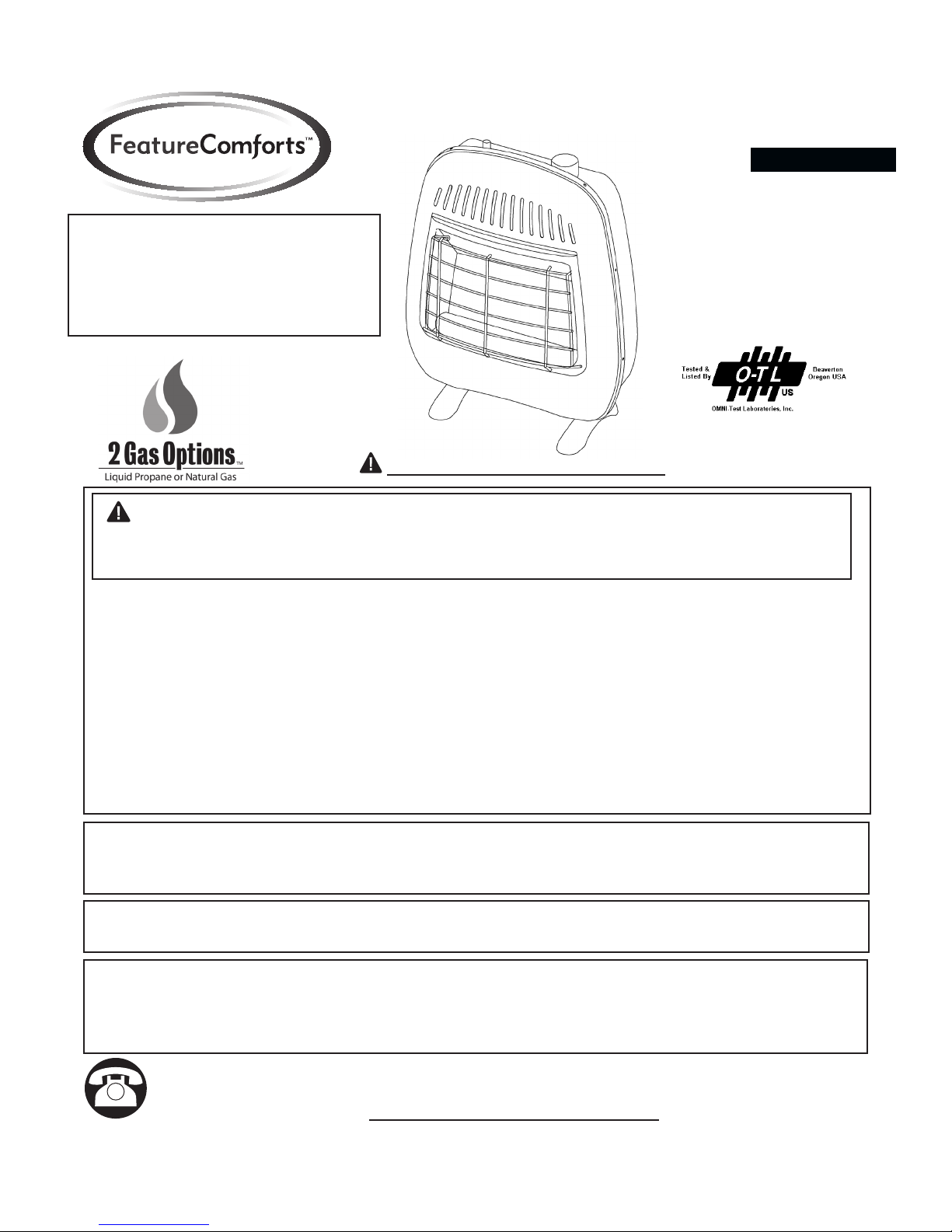
WARNING: This appliance is
equipped for (Natural and
Propane) gas. Field conversion is
not permitted other than between
natural or propane gases.
ITEM #0051064 0051118 0051186
VENT-FREE GAS WALL HEATER BLUE FLAME
MODEL #MD100TBE MD200TBE MD300TBE
Español p. 31
CAUTION - FOR YOUR SAFETY
WARNING: IF THE INFORMATION IN THIS MANUAL IS NOT FOLLOWED
EXACTLY, A FIRE MAY RESULT CAUSING PROPERTY DAMAGE, PERSONAL
INJURY, OR LOSS OF LIFE.
– Do not store or use gasoline or other ammable vapors and liquids in vicinity of this or any
other appliance.
WHAT TO DO IF YOU SMELL GAS:
• Do not try to light any appliance.
• Do not touch any electrical switch; do not use any phone in your building.
• Immediately call your gas supplier from a neighbor’s phone. Follow the gas
supplier’s instructions.
• If you cannot reach your gas supplier, call the re department.
– Installation and service must be performed by a qualied installer, service agency,
or the gas supplier.
This is an unvented gas-red heater. It uses air (oxygen) from the room in which it is
installed. Provisions for adequate combustion and ventilation air must be provided.
Refer to Air For Combustion and Ventilation section on page 7 of this manual.
INSTALLER : DO NOT DISCARD THIS MANUAL - LEAVE FOR HOMEOWNER'S
FUTURE REFERENCE.
This appliance may be installed in an aftermarket, permanently located manufactured
(mobile) home, where not prohibited by local codes. This appliance is for use with the
type of gas indicated on the rating plate only. This appliance is not convertible for use
with other gases.
Questions, problems, missing parts? Before returning to your retailer, call our
customer service department at 1-866-573-0674, 8:00 a.m - 4:30 p.m., EST,
Monday - Friday or e-mail customerservice@usaprocom.com
LS-SM-MDTBE-0805
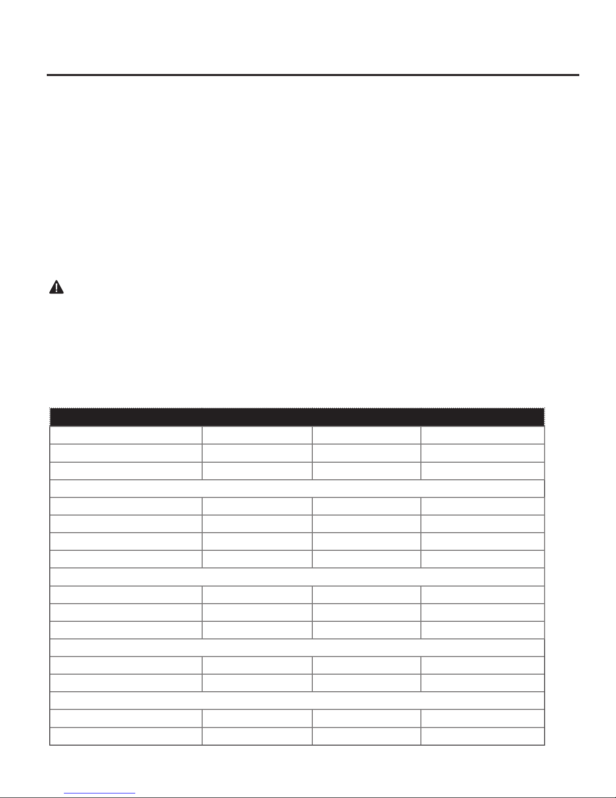
TABLE OF CONTENTS
Important Safety Information..........................................................................................................3
Product Features............................................................................................................................5
Air For Combustion and Ventilation................................................................................................7
Installation ....................................................................................................................................10
Operation......................................................................................................................................18
Care & Maintenance.....................................................................................................................22
Troubleshooting............................................................................................................................23
Replacement Parts.......................................................................................................................26
WARNING: READ THE INSTALLATION & OPERATION INSTRUCTIONS
BEFORE USING THIS APPLIANCE.
IMPORTANT: Read instructions and warnings carefully before starting installation.
Failure to follow these instructions may result in a possible re
hazard and will void the warranty.
PRODUCT SPECIFICATIONS
ITEM # 0051064 0051118 0051186
BTU (available) 10,000 20,000 30,000(NG) 28,000(LP)
Gas Type Using Natural Gas Using Natural Gas Using Natural Gas
Pressure Regulator Setting 4 in. W.C. 4 in. W.C. 4 in. W.C.
Inlet Gas Pressure* (inches of water) * For purposes of input adjustment.
Maximum 10.5 in. 10.5 in. 10.5 in.
Minimum * 5 in. 5 in. 5 in.
Gas Type Using Propane Gas Using Propane Gas Using Propane Gas
Pressure Regulator Setting 9 in. W.C. 9 in. W.C. 9 in. W.C.
Inlet Gas Pressure* (inches of water) * For purposes of input adjustment.
Maximum 14 in. 14 in. 14 in.
Minimum * 11 in. 11 in. 11 in.
Ignition Electric Piezo Electric Piezo Electric Piezo
Dimensions, Inches (HxWxD)
Heater 22.3 × 17.32 × 9.62 26.8 × 21 × 9.2 26.8 × 28.5 × 9.3
Carton 23.1 × 18.31 × 9.84 26.69 × 21.97 × 9.76 26.69 × 29.13 × 9.76
Weight (Pounds)
Heater 16.3 23.6 30.1
Shipping 21.5 30.3 37.2
2
IMPORTANT SAFETY INFORMATION
IMPORTANT: Read this owner’s manual carefully and completely before trying to assemble,
operate, or service this heater. Improper use of this heater can cause serious injury or death from
burns, re, explosion, electrical shock, and carbon monoxide poisoning.
Only a qualied installer, service agent, or local gas supplier may install and service this product.
WARNING: Do not store, use gasoline, other ammable vapors, liquids in the vicinity
of this or any other appliance.
CARBON MONOXIDE POISONING: Early signs of carbon monoxide poisoning resemble the
u with headaches, dizziness, or nausea. If you have these signs, the heater may not be working
properly. Get fresh air immediately! Have heater serviced. Some people are more affected by
carbon monoxide than others. These include pregnant women, people with heart or lung disease,
people who are anemic, those under the inuence of alcohol, and those living in high altitudes
NATURAL AND PROPANE/LP GAS: Natural and Propane/LP gases are odorless. An
odor-making agent is added to the gas. The odor helps you detect a gas leak. However, the odor
added to the gas can fade. Gas may be present even though no odor exists. Make certain you
read and understand all warnings. Keep this manual for reference. It is your guide to operating
this heater safely.
WARNING: Any change to this replace/heater or its controls can be dangerous.
WARNING: Do not use any accessories not approved for use with this heater.
WARNING: Carefully supervise young children when they are in the room with the heater.
WARNING: Heater becomes very hot when operating. Keep children and adults
away from hot surfaces to avoid burns or clothing ignition. Heater will remain hot for
a time after shutoff. Allow surfaces to cool before touching.
WARNING: Make sure grill guard is in place before running heater.
WARNING: Keep the appliance area clear and free from combustible materials,
gasoline, and other ammable vapors and liquids.
WARNING: Due to high temperatures, locate this appliance out of trafc and
away from furniture and draperies.
WARNING: Do not place clothing or other ammable material on or near the
appliance. Never place any objects in the heater.
3

1. Do not place Propane/LP supply tank(s) inside any structure. Place Propane/LP
supply tank(s) outdoors.
2. Do not install item #0051064 (Model #MD100TBE) in a bathroom. Do not install
Item #0051118 (Model #MD200TBE) and Item #0051186 (Model #MD300TBE)
in a bedroom or bathroom.
3. This heater needs fresh air ventilation to run properly. This heater has an Oxygen
Depletion Sensing (ODS) safety shutoff system. The ODS shuts down the heater
if not enough fresh air is available. See Air for Combustion and Ventilation, pages 7
through 9. If heater keeps shutting off, see Troubleshooting, pages 23 through 25.
4. Keep all air openings in front and bottom of heater clear and free of debris. This
will ensure enough air for proper combustion.
5. If heater shuts off, do not relight until you have provided fresh, outside air. If heater
keeps shutting off, have it serviced.
6. Do not run heater:
• Where ammable liquids or vapors are used or stored.
• Under dusty conditions.
7. Before using furniture polish, wax, carpet cleaner, or similar products, turn heater
off. If heated, the vapors from these products may create a white powder residue
within burner box or on adjacent walls or furniture.
8. Always run heater with control knob at 1,2,3,4,5 locked positions.
Never set control knob between locked positions. Poor combustion and higher
levels of carbon monoxide may result.
9. Do not use heater if any part has been under water. Immediately call a qualied
service technician to inspect the room heater and to replace any part of the control
system and any gas control which has been under water.
10. Turn off and unplug heater and let cool before servicing. Only a qualied service
person should service and repair heater.
11. Operating heater above elevations of 4,500 feet could cause pilot outage.
12. To prevent performance problems, do not use propane/LP fuel tank of less than
100 lbs. capacity.
QUALIFIED INSTALLING AGENCY
Only a qualied agency should perform installation and replacement of gas piping, gas
utilization equipment or accessories, and repair and servicing of equipment. The term
“qualied agency” means any individual, rm, corporation, or company that either in
person or through a representative is engaged in and is responsible for:
a) Installing, testing, or replacing gas piping or
b) Connecting, installing, testing, repairing, or servicing equipment; that is experienced
in such work; that is familiar with all precautions required; and that has complied with
all the requirement of the authority having jurisdiction.
4
PRODUCT FEATURES
SAFETY PILOT
This heater has a pilot with an Oxygen Depletion Sensing (ODS) safety shutoff system.
The ODS/pilot shuts off the heater if there is not enough fresh air.
PIEZO IGNITION SYSTEM
This heater is equipped with an electronic piezo control system. This system requires
AAA batteries (provided).
THERMOSTAT HEAT CONTROL
The control automatically cycles the burner on and off to maintain a desired room
temperature. See page 20.
2 GAS OPTIONS CAPABLE
Your heater is equipped to operate on either propane or natural gas. The heater is
shipped from the factory ready for connecting to propane. The heater can easily be
changed to natural gas by having your qualied installer follow the instructions on page
16 and the markings on the heater.
State of Massachusetts: The installation must be made by a licensed plumber or gas
tter in the Commonwealth of Massachusetts. Sellers of unvented propane or natural gasred supplemental room heaters shall provide to each purchaser a copy of 527 CMR 30
upon sale of the unit.
In the State of Massachusetts, unvented propane or natural gas-red space heaters shall
be prohibited in bedrooms and bathrooms.
In the State of Massachusetts the gas cock must be a T-handle type. The State of
Massachusetts requires that a exible appliance connector cannot exceed three feet
in length.
LOCAL CODES
Install and use heater with care. Follow all codes. In the absence of local codes, use the latest
edition of The National Fuel Gas Code, ANSI Z223.1, also known as NFPA 54*.
*Available from:
American National Standard Institute, Inc National Fire Protection Association, Inc.
1430 Broadway 1 Batterymarch Park
New York, NY 10018 Quincy, MA 02269-9101
This heater is designed for vent-free operation. State and local codes in some areas prohibit the
use of vent-free heaters.
5

PREPARING FOR INSTALLATION
Before beginning assembly or operation of the product, make sure all parts are present.
Compare parts with package contents list. If any part is missing or damaged, do not attempt to assemble, install, or operate the product. Contact customer service for
replacement parts.
Before installing heater, make sure you have the items listed below:
• piping (check local codes)
• sealant (resistant to natural gas and propane/LP gas)
• equipment shutoff valve*
• test gauge connection*
• sediment trap
• tee joint
• pipe wrench
• exible gas hose (check local codes)
* A CSA design-certied equipment shutoff valve with 1/8-inch NPT tap is an acceptable
alternative to test gauge connection. Purchase the optional CSA design-certied
equipment shutoff valve from your dealer.
UNPACKING
1. Remove heater from carton.
2. Remove all protective packaging applied to heater for shipping
3. Check heater for any shipping damage. If heater is damaged, promptly inform
dealer where you bought heater.
WATER VAPOR: A BY-PRODUCT OF UNVENTED ROOM HEATERS
Water vapor is a by-product of gas combustion. An unvented room heater produces
approximately one (1) ounce (30 mL) of water for every 1,000 BTUs (.3 kw) of gas input
per hour. Use an unvented room heater as a supplemental heater (a room) rather than a
primary heat source (an entire house). In most supplemental heat applications, the water
vapor does not create a problem. In most applications, the water vapor enhances the low
humidity atmosphere experienced during cold weather.
The following steps will help ensure that water vapor does not become a problem:
1. Be sure the heater is the proper size for the application, including adequate
combustion air and circulation air.
2. If there is high humidity, the dehumidier may be used to help lower the water vapor
content of the air.
3. Do not use an unvented room heater as the primary heat source.
6

AIR FOR COMBUSTION AND VENTILATION
WARNING: This heater should not be installed in a conned space or unusually tight
construction unless provisions are provided for adequate combustion and ventilation
air. Read the following instructions to ensure proper fresh air for this and other fuel burning
appliances in your home.
PRODUCING ADEQUATE VENTILATION
This heater shall not be installed in a room or space unless the required volume of indoor
combustion air is provided by the method described in the NATIONAL FUEL GAS CODE,
ANSI Z223.1/NFPA 54, the INTERNATIONAL FUEL GAS CODE, or applicable local codes.
The following are excerpts from National Fuel Gas Code, NFPA 54/ANSI Z223.1,Section
5.3, Air for Combustion and Ventilation. All spaces in homes fall into one of the three
following ventilation classications:
1. Unusually Tight Construction
2. Unconned Space
3. Conned Space
The information on pages 7 through 9 will help you classify your space and provide
adequate ventilation.
Conned and Unconned Space
The National Fuel Gas Code, ANS Z223.1 denes a conned space as a space whose
volume is less than 50 cu. ft. per 1,000 BTU/hr (4.8 m^3 per kw) of the aggregate input
rating of all appliances installed in that space and an unconning space as a space
whose volume is not less than 50 cu. ft. per 1,000 BTU/hr (4.8 m^3 per kw) of the
aggregate input rating of all appliances installed in that space. Rooms connecting
directly with the space in which the appliances are installed*, through openings not
furnished with doors, are considered a part of the unconned space.
This heater should not be installed in a conned space or unusually tight construction
unless provisions are provided for adequate combustion and ventilation air.
* Adjoining rooms are connecting only if there are doorless passageways or
ventilation grills between them
Unusually Tight Construction
The air that leaks around doors and windows may provide enough fresh air for
combustion and ventilation. However, in buildings of unusually tight construction, you
must provide additional fresh air.
Unusually tight construction is dened as construction where:
a) walls and ceilings exposed to the outside atmosphere have a continuous water vapor
retarder with a rating of one perm (6x10
gasketed or sealed and
b) weather stripping has been added on windows that can be opened and on doors and
c) caulking or sealants are applied to areas such as joints around window and door frames,
between sole plates and oors, between wall-ceiling joints, between wall panels, at
penetrations for plumbing, electrical, and gas lines, and at other openings.
If your home meets all of the three criteria above, you must provide additional fresh air.
See “Ventilation Air From Outdoors” (page 9). If your home does not meet all of the
three criteria above, proceed to “Determining Fresh-Air Flow For Heater Location”.
-11
kg per pa-sec-m2) or less with openings
7

DETERMINING FRESH-AIR FLOW FOR HEATER LOCATION
Determining if You Have a Conned or Unconned Space
Use this worksheet to determine if you have a conned or unconned space.
Space: Includes the room in which you will install heater plus any adjoining rooms with
doorless passageways or ventilation grills between the rooms.
1.
Determine the volume of the space: Length × Width × Height = cu. ft. (volume of space)
Example: Space size 20 ft. (length) × 16 ft.(width) × 8 ft. (ceiling height) = 2560 cu. ft.
(volume of space)
If additional ventilation to adjoining room is supplied with grills or openings, add the
volume of these rooms to the total volume of the space.
2. Divide the space volume by 50 cu. ft. to determine the maximum BTU/hr the space
can support.
_______ (volume of space) ÷ 50 cu. ft.= (Maximum BTU/hr the space can support)
Example: 2560 cu. ft. (volume of space) ÷ 50 cu. ft. = 51.2 or 51,200 (maximum
BTU/hr the space can support)
3. Add the BTU/hr of all fuel burning appliances in the space.
Vent-free heater BTU/hr
Gas water heater* BTU/hr
Gas furnace BTU/hr
Vented gas heater BTU/hr Example:
Gas heater logs BTU/hr Gas water heater 30,000 BTU/hr
Other gas appliances*+ BTU/hr Vent-free heater + 26,000 BTU/hr
Total = BTU/hr Total = 56,000 BTU/hr
*Do not include direct-vent gas appliances. Direct-vent draws combustion air from the
outdoors and vents to the outdoors.
4. Compare the maximum BTU/hr the space can support with the actual amount of BTU/hr
used.
_______ BTU/hr (maximum the space can support)
_______ BTU/hr (actual amount of BTU/hr used).
Example : 51,200 BTU/hr (maximum the space can support)
56,000 BTU/hr (actual amount of BTU/hr used)
The space in the above example is a conned space because the actual BTU/hr used is
more than the maximum BTU/hr the space can support.
You must provide additional fresh air. Your options are as follows:
a) Rework worksheet, adding the space of an adjoining room. If the extra space
provides an unconned space, remove door to adjoining room or add ventilation
grills between rooms. See “Ventilation Air From Inside Building,” page 9.
b) Vent room directly to the outdoors. See “Ventilation Air From Outdoors,” Page 9.
c) Install a lower BTU/hr heater if lower BTU/hr size makes room unconned. If the
actual BTU/hr used is less than the maximum BTU/hr the space can support, the
space is an unconned space. You will need no additional fresh air ventilation.
8
WARNING: If the area in which the heater may be operated is smaller than that dened as
an unconned space or if the building is of unusually tight construction, provide adequate
combustion and ventilation air by one of the methods described in the National Fuel Gas
Code, ANS Z223.1, Section 5.3 or applicable local codes.
WARNING: If the area in which the heater may be operated does not meet the required
volume for indoor combustion air, combustion and ventilation air shall be provided by one
of the methods described in the NATIONAL FUEL GAS CODE, ANSI Z223.1/NFPA 54, the
INTERNATIONAL FUEL GAS CODE, or applicable local codes.
Ventilation Air From Inside Building
Fig. 1 - Ventilation Air from
Inside Building
This fresh air would come from adjoining
unconned space. When ventilating to an
adjoining unconned space, you must
12 in.
provide two permanent openings: one
within 12 inches of the wall connecting
the two spaces (see options 1 and 2,
Fig. 1). You can also remove door into
adjoining room (see option 3, Fig. 1).
Follow the National Fuel Gas Code
Ventilation
Grills
Into Adjoining
Room,
Option 1
Or
Remove
Door
Into
Adjoining
Room,
Option 3
Ventilation Grills
Into adjoining Room,
Option 2
NFPA 54/ANS Z223.1. Air for Combustion
and Ventilation for required size of
12 in.
ventilation grills or ducts.
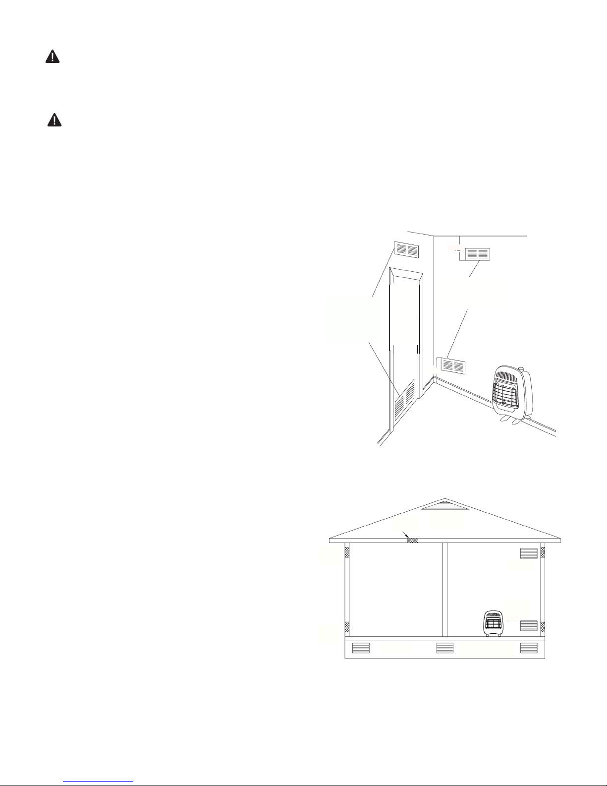
Ventilation Air From Outdoors
Provide extra fresh air by using ventilation
grills or duct. You must provide two
permanent openings: one within 12 inches
of the ceiling and one within 12 inches of
the oor. Connect these items directly to the
outdoors or spaces open to the outdoors.
These spaces include attics and crawl
spaces. Follow the National Fuel Gas Code
NFPA 54/ANS Z223.1. Air for Combustion
and Ventilation for required size
of ventilation grills or ducts.
IMPORTANT: Do not provide openings for
inlet or outlet air into attic if attic has a
thermostat-controlled power vent. Heated
air entering the attic will activate the
power vent. Rework worksheet, adding the
space of the adjoining unconned space.
The combined spaces must have enough
fresh air to supply all appliances in both
spaces.
Fig. 2 - Ventilation Air from
Outlet
Air
Outlet
Air
Inlet
Air
Inlet Air
Outdoors
Ventilated
Attic
To Attic
To Crawl
Space
Ventilated
Crawl Space
9
 Loading...