

OWNER’S MANUAL
ENCLOSED TRAILERS

Thank You…
From Featherlite Trailers
Dear Customer,
Thank you for purchasing a Featherlite Trailer.
You are now part of tens of thousands in North America who enjoy Featherlite Trailers
for their premium grade construction, innovative features and custom interiors.
Featherlite builds hundreds of different standard and custom-designed aluminum
specialty trailers and transporters. For each and every one, customer satisfaction is
Featherlite’s passion and safety is top priority.
Featherlite knows the most important thing that goes into each and every trailer is what
you, our customer, put in it. That is why the features of all Featherlite trailers are engineered
with the customer and the cargo in mind.
Please know that Featherlite’s dedicated dealers and employees are here for you. Let
Featherlite know how we can be of service now and in the future.
Thanks again and best wishes!
Featherlite Trailers
P.S. Keep current on Featherlite’s innovative new trailers at www.fthr.com.
THANK YOU FOR CHOOSING FEATHERLITE!
Copyright 2015 by Featherlite, Inc. All rights reserved. No part of this publication may be reproduced or transmitted
in any form or by any means, electronic or mechanical, including photocopy, recording or any information storage
and retrieval system, without permission in writing from the copyright proprietor rst obtained.

^ WARNING
This User’s Manual contains safety
information and instructions for your
Featherlite, Inc.
MODEL ENCLOSED TRAILERS
Featherlite, Inc.
800-800-1230 Phone
563-547-6100 Facsimile
trailer.
You must read this manual before loading
or towing your trailer.
You must follow all safety pre cautions and
instructions.


Table of Contents
ENCLOSED TRAILERS
1 SAFETY INFORM ATION .......................................... 1
1.1 SAFETY ALERT SYMBOLS AND SIGNAL WORDS ...... 1
1.2 MAJOR HAZARDS .................................................... 1
1.2.1 Improper Sizing of Trailer to Tow Vehicle. ....... 1
1.2.2 Driving Too Fast ............................................... 2
1.2.3 Failure to Adjust D riv ing Behavi or W hen T owi ng
a Trailer ............................................................. 2
1.2.4 Improper Loading.............................................. 2
1.2.5 Trailer Not Properly Coupled to the Hitch ........ 2
1.2.6 Proper Use of Safety Chains ............................. 3
1.2.7 Proper Connection of Breakaway Brake ........... 3
1.2.8 Matching Trailer and Hitch ............................... 4
1.2.9 Worn Tires, Loose Wheels and Lug Nuts ........... 4
1.2.10 Weight And Load Distribution ........................... 4
1.2.11 Shifting Cargo ................................................... 5
1.2.12 Inappropriate Cargo ......................................... 5
1.2.13 Inoperable Brakes, Lights or Mirrors ............... 6
1.2.14 Hazards From Modifying Your Trailer ............ 6
1.2.15 Hazards to Horses (Horse Trailer) .................... 7
1.2.16 Hazards to Livestock (Livestock Trailer) ........... 7
1.2.17 Hazards from Ac cessories ................................. 7
1.2.18 Generator .......................................................... 7
1.2.19 Shore Power ...................................................... 8
1.2.20 LP Gas Fuel System........................................... 8
1.2.21 Trailer Towing Guide ........................................ 9
1.2.22 Safe Trailer Towing Guidelines ......................... 9
1.2.23 Safety Warning Labels on Your Trailer ........... 11
1.2.24 Reporting Safety Defects ................................. 12
2 TIRE SAFETY INFORMATION ............................. 13
2.1 TRAILER TIRE INFORMATION ................................ 13
2.2 STEPS FOR DETERMINING CORRECT LOAD LIMIT –
TRAILER................................................................ 14
2.2.1 Trailers 10,000 Pounds GVWR or Less ........... 15
2.2.2 Trailers Over 10,000 Pounds GVWR .............. 15
2.3 STEPS FOR DETERMINING CORRECT LOAD LIMIT –
TOW VEHICLE ....................................................... 15
2.4 GLOSSARY OF TIRE TERMINOLOGY ...................... 15
2.5 TIRE SAFETY - EVERYTHING RIDES ON IT ............. 18
2.5.1 Safety First–Basic Tire Maintenance .............. 19
2.5.2 Finding Your Vehicle's Recommended Tire
Pressure and Load Limits ................................ 19
2.5.3 Understanding Tire Pressure and Load Limits 19
2.5.4 Checking Tire P ressure ................................... 19
2.5.5 Steps for Maintaining Proper Tire Pressure ... 19
2.5.6 Tire Size ........................................................... 20
2.5.7 Tire Tread ........................................................ 20
2.5.8 Tire Balance and Wheel Alignment ................. 20
2.5.9 Tire Repair ...................................................... 20
2.5.10 Tire Fundamentals .......................................... 20
2.5.10.a Information on Passenger Vehicle Tires ......... 20
2.5.10.b UTQGS Information ....................................... 21
2.5.10.c Information on Light Truck (LT) Tires .......... 21
2.5.10.d Information on Special Trailer (ST) Tires ...... 22
2.5.11 Tire Safety Tips ................................................ 22
3 COUPLING TO THE TOW VEHICLE .................. 24
3.1 USE AN ADEQUATE TOW VEHICLE AND HITCH ...... 24
3.1.1 Trailer Information .......................................... 24
3.1.2 Tow Vehicle...................................................... 25
3.2 COUPLING AND UNCOUPLING THE TRAILER ........... 26
3.2.1 Trailer with Ball Hitch Coupler ....................... 27
3.2.1.a Before Coupling Trailer to Tow Vehicle ........ 28
3.2.1.b Prepare the Coupler and Hi tch ....................... 29
3.2.1.c Couple the Trailer to the Tow Vehicle (Cequent
Coupler).......................................................... 29
3.2.1.d Couple the Trailer to the Tow Vehicle (Demco
Coupler).......................................................... 29
3.2.1.e Rig the Safety Chains ..................................... 30
3.2.1.f Attach and Test Breakaway Brake System ..... 31
3.2.1.g Connect the Electrical Cables ......................... 32
3.2.1.h Uncoupling the Ball Hitch Trailer .................. 32
3.2.2 Trailer with Gooseneck Coupler and Drop-Leg
Jack .................................................................. 32
3.2.2.a Adjust Gooseneck Hitch Height ..................... 33
3.2.2.b Drop-Leg Jack(s) ............................................ 34
3.2.2.c Before Coupling Trailer to Tow Vehicle ........ 34
3.2.2.d Prepare Ball Receiver and Gooseneck Ball .... 35
3.2.2.e Couple the Trailer to the Tow Vehicle ........... 35
3.2.2.f Rig the Safety Chains ..................................... 36
3.2.2.g Attach and Test Breakaway Brake System ..... 36
3.2.2.h Connect the Electrical Cables ......................... 37
3.2.2.i Uncoupling the Goosen ec k T ra il er with Drop-Leg
Jack ................................................................. 38
3.2.3 Trailer with Fifth Wheel Coupler and Drop-Leg
Jack .................................................................. 38
3.2.3.a Before Coupling Trailer to the Tow Vehicle .. 39
3.2.3.b Adjust Hitch Height ........................................ 39
3.2.3.c Prepare the Fifth Wheel Coupler .................... 40
3.2.3.d Couple the Trailer to the Tow Vehicle ........... 40
3.2.3.e Attach and Test Breakaway Brake System ..... 41
3.2.3.f Connect the Electri cal Cables ......................... 42
3.2.3.g Uncoupling the Fifth Wheel Trailer ............... 42
4 LOADING THE TRAILER ....................................... 44
4.1 CHECKING TONGUE WEIGHT ................................. 45
4.2 LOADING CARGO (ENCLOSED TRAILER) ................ 46
4.2.1 Preparing the Trailer for Loading ................... 46
4.2.2 Loading the Enclosed Trailer .......................... 46
4.3 LOADING HORSES (HORSE TRAILER) ..................... 47
4.3.1 Preparing the Horse Trailer for Loading ........ 47
4.3.2 Loading the Horse Trailer ............................... 48
4.4 LOADING LIVESTOCK (LIVESTOCK TRAILER) ......... 49
4.4.1 Preparing the Livestock Trailer for Loading ... 49
4.4.2 Loading the Livestock Trailer .......................... 50
4.5 SECURING THE CARGO ........................................... 50
5 CHECKING THE TRAILER BEFORE AND DURING
EACH TOW ......................................................................... 51
5.1 PRE-TOW CHECKLIST ............................................ 51
5.2 MAKE REGULAR STOPS ......................................... 51
6 BREAKING-IN A NEW TRAILER .......................... 52
6.1 RETIGHTEN LUG NUTS AT FIRST 10, 25 & 50 MILES52
6.2 ADJUST BRAKE SHOES AT FIRST 200 MILES (AXLES
RATED 8000 LBS AND BELOW WITH HYDRAULIC BRAKES AND
ALL AXLES WITH AIR BRAKES) ......................................... 52
i
Table of Contents
^ WARNING
This User’s Manual contains safety
information and instructions for your
ENCLOSED TRAILERS
6.3 SYNCHRONIZING THE BRAKE SYSTEMS .................52
6.4 TIRE PRESSURE......................................................52
7 ACCESSORIES...........................................................53
7.1 GASOLINE OR DIESEL-POWERED ELECTRIC
GENERATORS ........................................................53
7.2 ACCESSORY BATTERY ...........................................53
7.3 SHORE POWER .......................................................54
7.4 LP GAS FUEL SYSTEM ...........................................54
7.4.1 LP Gas System Troubleshooting ......................55
7.5 VENDING & ACCESSORY DOORS ...........................55
7.6 ELECTRIC- POWERED LANDING GEAR ...................56
8 INSPECTION, SERVICE & MAINTENANCE .......57
8.1 INSPECTION, SERVICE & MAINTENANCE SUMMARY
CHARTS .................................................................57
8.2 INSPECTION AND SERVICE INSTRUCTIONS ..............59
8.2.1 Axle Bolts, Frame, Suspension, & Structure ....59
8.2.2 Trailer Structu re ...............................................59
8.2.2.a Fasteners and Frame Members .......................59
8.2.2.b Welds ..............................................................60
8.2.3 Drop Ramp Torsion Springs ............................60
8.2.4 Slide-Outs .........................................................60
8.2.5 Trailer Brakes (Nev-R-Adjust® Forward Adjusti ng
Brakes) .............................................................60
8.2.5.a Periodic Inspection .........................................61
8.2.5.b Brakes, Electric ...............................................61
8.2.5.c Brakes, Hydraulic (Vacuum, Air or Electric
Operated) ........................................................61
8.2.6 Trailer Brakes (Axles Rated 8000 lbs and Below
with Hydraulic Brakes and ALL Axles with Air Brakes)
8.2.6.a Initial Inspection .............................................62
8.2.6.b Periodic Inspection .........................................62
8.2.6.c Manually Adjusting Brake Shoes ...................62
8.2.6.d Brakes, Hydraulic (Vacuum, Air or Electric
Operated) ........................................................62
8.2.7 Trailer Connection to Tow Vehicle ..................63
8.2.7.a Coupler and Ball .............................................63
8.2.7.b Gooseneck ......................................................63
8.2.7.c Fifth Wheel Kingpin .......................................63
8.2.8 Landing Leg or Jack ........................................63
8.2.9 Lights and Signals ............................................64
8.2.10 Accessory Battery .............................................64
8.2.11 Feed Door Lat ches (Horse Trailers) ................64
8.2.12 Tires .................................................................64
8.2.13 Wheel Rims .......................................................64
8.2.14 Wheel Liners (Simulators) ................................64
8.2.15 Wheel Bearings ................................................65
8.2.15.a Standard Bearin gs ...........................................65
8.2.15.b E-Z Lube® Bearings (Standard Equipment on
Axles Rated 8000 lbs. and Below) ..................66
8.2.15.c Nev-R-Lube™ or Other Seal ed Bearings ....66
8.2.16 Lug Nuts (Bolts) ...............................................66
9 TECHNICAL REFERENCE .....................................69
9.1 TRAILER LIGHTING ELECTRICAL CONNECTION ......69
9.2 HITCH SYSTEMS ....................................................70
trailer.
You must read this manual before loading
or towing your trailer.
You must follow all safety pre cautions a nd
instructions.
“Portions of this manual were used with the expressed
authority of Dexter Axle, but Dexter Axle is not responsible
for the accuracy of the information contained herein.”
62
ii
1 SAFETY INFORMATION
^ DANGER
^ WARNING
^ CAUTION
NOTICE
1.1 SAFETY ALERT SYM BOLS AND SIGNAL
WORDS
This manual provides instructions for the operation
and care of Featherlite Horse, Livestock and
Enclosed Trailers. The instruction s in this manual
must be followed to ensure the safety of persons,
horses and livestock, and satisfactory life of the
trailer. Safety precautions to protect against injury
or property damage must be followed at all times.
An Owner’s Manu al that provides general trailer
information cannot cover all of the specific details
necessary for the proper combination of every
trailer, tow vehicle and hitch. Therefore, you must
read, understand and follow the instructions given
by the tow vehicle and trailer hitch manufactu rers,
as well as the instructions in this man ual.
Our trailers are built with components produced by
various manufacturers. Some of these items have
separate instruction manuals. Where this manual
indicates th at y o u sh oul d re ad a not he r ma nua l, and
you do not have that manual, call Featherlite, Inc. at
800-800-1230 or your dealer for assistance.
The safety information in this manual is denoted by
the safety alert symbol: ^
The level of risk is indicated by the foll owing sig nal
words.
CAUTION – Hazards or unsafe practices
which could result in minor or moderate
injury if the warning is ignored.
NOTICE – Practices that could result in
damage to the trailer or other property.
1.2 MAJOR HAZARDS
Loss of control of the trailer or trailer/tow vehicle
combination can result in d eath or serious injury.
The most common causes for loss of control of the
trailer are:
• Improper sizing the trailer for the tow vehicle,
or vice versa.
• Excessive Speed: Driving too fast for the
conditions.
• Failure to adjust driving behavior when towing
a trailer.
• Overloading and/or improper weight
distribution.
• Improper or mis-coupling of the trailer to the
hitch.
• Improper braking and steering under sway
conditions.
• Not maintaining proper tire pressure.
• Not keeping lug nuts tight.
DANGER – Immediate hazar ds which WILL
result in severe personal injury or death if
the warning is ignored.
WARNING – Hazards or unsafe practices
which COULD result in severe personal
injury or death if the warning is ignored.
R6 3/30/2017 Page 1
1.2.1 Improper Sizing of the Trailer to the
Tow Vehicle.
Trailers that weigh too much for the towing vehicle
can cause stability problems, which can lead to
death or serious injury. Furthermore, the additional
strain put on t he e ngine and dri ve-train may lead to
serious tow vehicle maintenance problems. For
these reasons the maximum towing capacity of y our
towing v ehicle should not be excee ded. The t ow ing
capacity of your tow vehicle, in terms of maximum
Gross Trailer Weight (GTW) and maximum Gross
Combined Weight Rating (GCWR) can be found in
the tow vehicles Owner’s Manu al.
Section 1 – Safety Information
^ DANGER
^ WARNING
^ WARNING
Use of an under-rated hitch, ball or tow
vehicle can result in l oss of control leading
to death or serious injury.
Make certain your hitch and tow vehicle ar e
rated for your tra iler.
1.2.2 Driving Too Fast
With ideal road conditions, the maximum
recommended speed for safely towing a trailer is 60
mph. If you drive too fast, the trailer is more likely
to sway, thus increasing the possibility for loss of
control. Also your tires may overheat, thus
increasing the possibility of a blowout.
• When encountering trailer sway, take your foot
off the accelerator, and steer as little as poss ible
in order to stay on the road. Use small “trimlike” steering adjustments. Do not attempt to
steer out of the sway; you’ll only m ake it w orse .
Also, do not apply the tow vehicle brakes to
correct trailer swaying. The application of the
trailer brakes alone will tend to straighten out
the combination, especially when going
downhill.
• Check rearview mirrors frequently to observe
the trailer and traffic.
• Use lower gear when driving down steep or
long grades. Use the en gine an d transmission
as a brake. Do not ride the brakes, as they can
overheat and become ineffective.
• Be aware of your trailer height , espe cial ly when
approaching bridges, roofed areas and around
trees.
Driving too fast for conditions can res ult in
loss of control and cause death or serious
injury.
Adjust speed down when towing trailer.
1.2.3 Failure to Adjust Driving Behavior
When Towing a Trailer
When towing a trailer, you will have decreased
acceleration, increased stopping distance, and
increased turning radius (which means you must
make wider turns to keep from hitting curbs,
vehicles, and anything else that is on the inside
corner). Furthermore, the trailer will change the
handling characteristics of your towing vehicle,
making it more sensitive to steering inputs and
more likely to be pushed around in windy
conditions or when being passed by large vehicles.
In additio n, y ou will need a longer distance to pass,
due to slower acceleration and increased length.
With this in mind:
• Be alert for slippery conditions. You are more
likely to be affected by slippery road surfaces
when driving a tow vehicle with a trailer, than
driving a tow vehicle without a trailer.
• Anticipate the trailer “swaying.” Swaying can
be caused by excessive steering, wind gusts,
roadway edges, or by the trailer reaction to the
pressure wave created by passing trucks and
busses.
1.2.4 Improper Loading
The total weight of the load you put in or on the
trailer, plus the empty weight of the trailer itself,
must not exceed the trailer's Gross Vehicle Weight
Rating (GVWR). If you do not know the empty
weight of the trailer, you must measure it at a
commercial scale. In addition, you must distribute
the load in the trailer such that the load on any axle
does not exceed the Gross Axle Weight Rating
(GAWR). The GVWR and GAWR’s are listed on
the Certification / VIN lab el mounted on the front
left side of the trailer.
An overloaded trailer can result in failu re or
in loss of control of the trailer, leading to
death or serious injury.
Never load a trailer so that the weight on
any tire exceeds its rating.
Never exceed the trailer Gross Vehicle
Weight Rating (GVWR).
Never exceed an axle Gross Axle Weight
Rating (GAWR).
1.2.5 Trailer Not Properly Coupled to the
Hitch
It is critical that the trailer be securely coupled to
the hitch, and that the safety chains and emergency
breakaway brake lanyard are correctly attached.
R6 3/30/2017 Page 2
Section 1 – Safety Information
^ WARNING
^ WARNING
^ WARNING
^ WARNING
tow the trailer if the breakaway brake
Uncoupling may result in death or serious injury to
you and to others.
Coupler and hitch selection and condition
are critical for safe towing.
Uncoupling can result in death or serious
injury.
• Make sure the h itch and ball are rated
for the trailer.
• Make sure the h itch [b all size] match es
the coupler.
• Check the hitch ball for wear, corrosi on
and cracks before coupling. Replace
worn, corroded or cracked hitch ball
before coupling to the trailer.
• Make sure the hitch ball is tight to the
hitch before coupling the trailer.
An improperly coupled trailer can result in
death or serious injury.
Do not move the trailer until:
• The coupler is secured and locked;
• The safety chains are secured to the
tow vehicle; and
• The trailer jacks are fully retracted.
Do not tow the trailer on the road until :
• The trailer brakes are checked;
• The breakaway switch is con nected to
the tow vehicle;
• The load is secured to the trailer; and
• The trailer lights are connected and
checked.
1.2.6 Proper Use of Safety Chains
Incorrect rigging of the safety chains can
result in loss of control of the trailer and
tow vehicle, leading to death or serious
injury, if the trailer uncouple s from the tow
vehicle.
Chains must:
• Fasten to frame of tow vehicle, not to
hitch or ball.
• Cross underneath hitch and coupler
with minimum slack to permit turning
and to hold tongue up, if the trailer
comes loose.
1.2.7 Proper Connection of Breakaway
Brake
If equipped with brakes, your trailer will be
equipped with a b reakaway brake system that can
apply the brakes on your trailer, if your trailer
comes loose from the hitch for an y reason. You
will have a separate set of instructions for the
breakaway brake if your trailer i s so equi pped. The
breakaway brake system, including battery, m ust be
in good condition and properly rigged to be
effective.
An ineffective breakaway brake system can
result in a runaway tr ailer, l eading to death
or serious injury if the coupler or ball hitc h
fails.
Test the function of the breakaway brake
system before towing the trailer. Do not
system is not working; have it serviced or
repaired.
Connect the breakaway lanyard to the tow
vehicle -
Safety chains are provided so that control of the
trailer can still be maintained if the trailer comes
loose from the tow vehicle for any reason.
R6 3/30/2017 Page 3
NOT to the safety chain; and
NOT to the hitch, ball or support.
Section 1 – Safety Information
^ DANGER
^ WARNING
cause an
loss of
^ WARNING
^ WARNING
^ WARNING
1.2.8 Matching Trailer and Hitch
Use of an under-rated hitch, ball or tow
vehicle can result in l oss of control leading
to death or serious injury.
Make certain your hitch and tow vehicle ar e
rated for your tra iler.
1.2.9 Worn Tires, Loose Wheels and Lug
Nuts
Just as with your tow vehicle, the trailer tires and
wheels are important safety items. Therefore, it is
essential to inspect the trailer tires before each tow.
If a tire has a bald spot, bulge, cu t, cracks, or is
showing any cords, replace th e tire before towing.
If a tire has uneven tread wear, take the trailer to a
dealer service center for di agnosis. Uneven tread
wear can be caused by tire imbalance, axle
misalignment or incorrect inflation.
Tires with too little tread will not provide adequate
frictional forces on wet roadways and can result in
loss of control, leading to death or serious injury.
Improper tire pressure causes increased tire wear
and may reduce trailer stability, which can result in
a tire blowout or possible loss of control.
Therefore, before each tow you must also check the
tire pressure. Remember, the proper tire pressure is
listed on the Certification (VIN) label, and should
be checked when tires are cold. Allow 3 hours
cool-down after driving as much as 1 mile at 40
mph before checking tire pressur e.
Metal creep between the wheel rim and lug
nuts (bolts) will cause rim to loosen.
Death or injury can occur if w heel comes
off.
Tighten lug nuts (bolts) before each tow.
The proper tightening sequence and tightness
(torque) for lug nuts is listed in the “Inspection,
Service & Maintenance” chapter of this manual.
Use a calibrated torqu e wrench to tighten the lug
nuts.
Lug nuts are also prone to loosen after first being
assembled. When drivin g a new trailer (or after
wheels have been remounted), check to make sure
they are tightened to t he proper tor que after the first
10, 25 and 50 miles of dr ivi ng and before each tow
thereafter.
Failure to perform this check can result in a wheel
parting from the trailer and a crash, leading to death
or serious injury.
Lug nuts are prone to loosen after being
first assembled. Death or serious injury
can result.
Check lug nuts for tightness on a new
trailer, and after re-mounting a wheel at 10,
25 and 50 miles.
Improper tire pressure may
unstable trailer. Blowout and
control may occur. Death or serious injury
can result.
Make sure of proper tire pressure before
towing trailer. Inflate tires to pressure
indicated on Certifica tion / VIN label.
The tightness of the lug nuts is very important in
keeping the wheels properly seated to the hub.
Before each tow, check to make sure they are
tightened to the proper torque.
R6 3/30/2017 Page 4
Inadequate lug nut torque can cause a
wheel to part while towing. Death or
serious injury can result.
Make sure lug nuts are tight befor e towing
trailer.
1.2.10 Weight And Load Di stribution
Proper loading of your trailer is essential for your
safety. Tire, wheel, axle or structural failure can be
caused by overloading.
Section 1 – Safety Information
^ WARNING
^ WARNING
Keeping the center of gravity low and
^ WARNING
sized fasteners, ropes, straps, etc. to
prevent the load from shifting while
^ WARNING
go may be
serious injury to the animals or other
An overloaded trailer can result in failu re or
in loss of control of the trailer, leading to
death or serious injury.
Never load a trailer so that the weight on
any tire exceeds its rating.
Never exceed the trailer Gross Vehicle
Weight Rating (GVWR).
Never exceed an axle Gross Axle Weight
Rating (GAWR).
Improper front / rear load distribution can lead to
poor trailer sway stability or poor tow vehicle
handling. Poor trailer sway stability results from
tongue weights that are too low, and poor tow
vehicle stability results from tongue weights that are
too high.
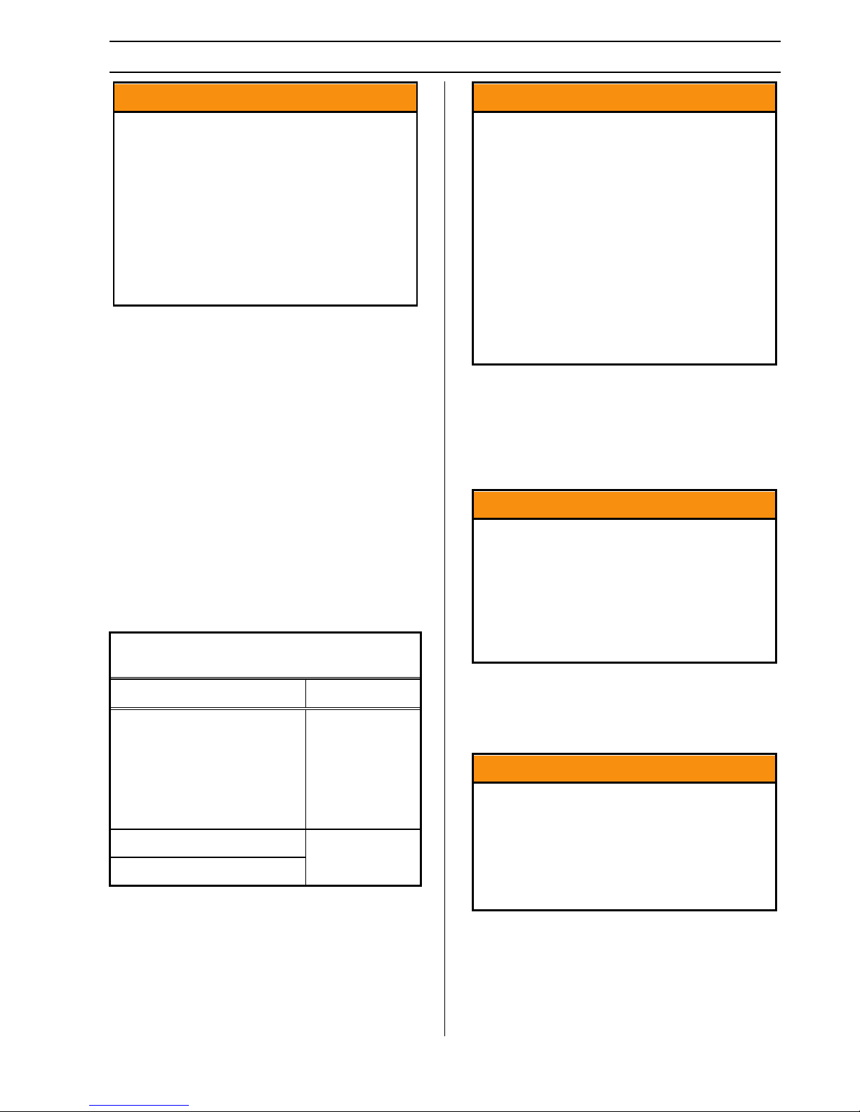
In figure 1-1, the second column shows th e rule of
thumb percentage of total weight of the trailer, plus
its cargo (Gross Trailer Weight, or “GTW”) that
should appear on the tongue of the trailer. For
example, a trailer with a gooseneck hitch , with a
loaded weight of 12,000 pounds, should have 2025% of 12,000 pounds (2400-3000 lbs.) on the
gooseneck. After loading, be sure to check that
none of the axles are overloaded.
Tongue Weight as a Percentage of Loaded
Trailer Weight
Type of Hitch Percentage
10–15% for
large trailers
Ball Hitch (or Bumper Hitch)
6-10% for
smaller utility
and cargo
trailers
An improperly distributed loa d can resu lt in
loss of control of the trail er, and can l ead to
death or serious injury.
Proper tongue weight is essential for stable
trailer handling.
Distribute the load front to rear to provide
proper tongue weight.
Distribute the load evenly, right a nd left, to
avoid tire overload.
centered is essential to minimize the risk o f
tip-over.
1.2.11 Shifting Cargo
Since the trailer “ride” can be bumpy and rough,
you must secure your cargo so that it does not shift
while the trailer is being towed.
A shifting load can result in failure, or to
loss of control of the trail er, and can l ead to
death or serious injury.
You must tie down all loads with proper
trailering.
If the door latch is equipped with a catch that has a
hole for a linchpin, use a linchp in to prevent the
door latch from opening.
Always secure the door latch after closing.
Place a linchpin in the catch.
Gooseneck Hitch
Fifth Wheel Hitch
Tongue Weight Chart – Figure 1-1
Uneven left / right load distribution can cause tire,
wheel, axle or structural failure. Be sure your
trailer is evenly loaded left / right.
Towing stability also depends on kee ping the cente r
of gravity as low as possible.
R6 3/30/2017 Page 5
20–25%
If the door opens, your car
ejected onto the road, resulting in dea th or
drivers.
1.2.12 Inappropriate Cargo
Your trailer may be designed for specific cargo, for
example, only for horses. If your trailer is designed
for specific cargo, only carry that cargo in the
trailer. Your trailer must not be used to carry
Section 1 – Safety Information
^ DANGER
You can die or be brain damaged by
^ WARNING
Never transport people inside your
Featherlite trailer, even if it has living
^ WARNING
^ WARNING
^ WARNING
^ WARNING
certain items, such as people, containers of
hazardous substan ces or containers of flammable
substances. A trailer not designed with living
quarters should only be used for transportation of its
intended cargo.
Carbon Monoxide.
Do not operate a generator , portabl e gril ls,
portable heaters, portable lanterns or
portable stoves inside the trailer.
quarters. Besides putting th eir lives at risk,
the transport of people may be illegal.
Check the trailer taillights by turning on your tow
vehicle headlights. Check the trailer br ake l ights by
having someone step on the tow vehicle br ake pedal
while you look at trailer lights. Check the turn
signal lights by operating the turn signal leve r in t he
tow vehicle.
If your trailer has electric brakes, your tow vehicle
will have an electric brake controller that sends
power to the trailer brakes. Before towing the
trailer on the road, you must operate the brake
controller while trying to pull the trailer in order to
confirm that the electric brakes operate. While
towing the trailer at less than 5 mph, manually
operate the electric brake controller in the tow
vehicle cab. You should feel the op eration of the
trailer brakes.
Failure to connect the tow vehicle lighting
and braking to the trailer will result in
inoperable lights and br ake s, and c an l ead
to collision.
Do not sleep in a trailer not equipped with
living quarters.
A trailer not designed with living quarters
should only be used for transportation of
its intended cargo.
Your Featherlite trailer is not capable of
safely transporting flammable, explosive,
poisonous or other dangerous materials.
Do not haul “loose” livestock in y our hor se
trailer.
Use a trailer designed to haul “loose”
livestock.
1.2.13 Inoperable Brakes, Light s or Mi rrors
Be sure that the brakes (if equipped) and all of the
lights on your trailer are functioning properly before
towing your trailer. Electric brakes and lights on a
trailer are controlled via a connection to the tow
vehicle, generally a multi-pin electrical connector.
R6 3/30/2017 Page 6
Check that all the trailer lights an d brakes
work before each tow.
If your trailer has hydraulic “surge” brakes, pull the
emergency breakaway brake lanyard to check the
operation of the surge mechanism.
Standard mirrors usually do not provide adequ ate
visibility for viewing traffic to the sides and rear a
towed trailer. You must provide mirrors that allow
you to safely observe approaching traffic.
1.2.14 Hazards From Modifying Your
Trailer
Essential safety items and structural integrity can be
damaged by altering your trailer. Even simply
driving a nail or screw can damage an electrical
circuit, LP gas line or other feature of the trailer.
Before making any alteration to your tr ailer , con tact
your dealer or Featherlite, Inc. at 800-800-1230
describe the alteration you are contemplating.
Alteration of the trailer structure or modification of
mechanical, electrical, plumbing, heating or other
systems on your trailer must be performed only by
qualified technicians who are familiar with the
system as installed on your trailer.
and
Section 1 – Safety Information
^ WARNING
^ WARNING
^ CAUTION
^ CAUTION
^ WARNING
Large animals are capable of inflicting
^ CAUTION
1.2.15 Hazards to Horses (Horse Trailer)
Before hauling a h orse, you must be aware of its
temperament.
The layout of a horse trailer is designed to safely
contain your horse. The trailer is equ ipped with
stall dividers and tie rings to secure the horse, and
has a rubber floor mat to keep shoed horses from
slipping on the metal underfloor. Restraining a
horse without using a combination of a tie -strap and
stall dividers may result in serious injury or death to
the horse.
Before loading your horse, inspect the in terior of
the horse trailer to insure that no hazards are
present. Read section 4.3 “Loading Horses (Horse
Trailer)” for specific instructions regarding
trailering of horses.
Handling a horse that is not traileracclimated may r esult in inj ury or death, or
damage to your trailer.
Hauling a horse in a livestock trailer may
result in its serious injury or death.
Do not carry a horse in a livestock trailer.
Use a trailer designed to carry horses.
1.2.16 Hazards to Livestock (Livestock
Trailer)
A livestock trailer is designed for the safe transport
of livestock, other than horses. It is not equipped
for hauling horses.
Before loading your livestock, inspect the interior of
the livestock trailer to insure that no hazards are
present. Read section 4.4, “Loading Livestock
(Livestock Trailer)” for specific instructions
regarding trailering of livestock other than horses.
Do not haul an unbroken horse in this
trailer.
Horses must have a halter.
Failure to secure a horse using a tie strap
may result in serious injury or death to
persons and/or the horse.
The interior space of a trailer may contain
hazards that result in serious injury or
death to a trailered horse.
Inspect the interior of the trailer before
loading a horse.
Adjust or repair all loose and protruding
features such as handles, loose or broken
parts of the trailer, etc.
Lock all stall divider s before towing
trailer.
All saddles, tack and equipment, as well
as horse(s), must be prevented from
being thrown about before towing trailer.
serious injury o r death to a human handle r.
Know your animals before attempting to
trailer them.
Hauling a horse in a livestock trailer may
result in its serious injury or death.
Do not carry a horse in a livestock trailer.
Use a trailer designed to carry horses.
1.2.17 Hazards from Accessories
The “Accessories” chapter of this manual contains
some information about certain optional accessories
that may be on your trailer. Read and follow all of
these instructions before operating the accessories.
The major hazards from some of these accessories
are:
1.2.18 Generator
If your trailer is equipped with a gasoline or diesel
generator, you must have and follow the generator
manufacturer’s instruction s. You must also have
one or more carbon monoxide detectors in the
trailer's accommodation spaces.
R6 3/30/2017 Page 7
Section 1 – Safety Information
^ WARNING
^ WARNING
^ WARNING
^ DANGER
You can die or be brain damaged by
Make certain the exhaust from LP
in the accommodation spaces of your
trailer before operating any LP gas
es, portable lanterns or portable
^ WARNING
Carbon Monoxide is an odorless gas that can cause
death. Be certain exhaust from a running generator
does not accumulate in or around your trailer, by
situations such as:
• Being drawn in by fans or ventilators operated
in a trailer;
• Prevailing wind;
• Being trapped between your trailer and other
trailers, vehicles or buildings; or
• Being trapped between your trailer and, or in a
snow bank, or other nearby objects
Risk of fire.
Connect only to source of correct voltage.
Do not overload electrical circuits.
Do not use an extension cord to connect to
shore power.
Replace fuses with like rating.
1.2.20 LP Gas Fuel System
Gasoline and diesel generators pose a risk
of death from:
• Carbon Monoxide
• Fire and Explosion
• Electrocution
Do not operate a generator without ha ving
a working carbon monoxide detector.
Do not refuel a running generator.
Do not refuel near ignition sources.
1.2.19 Shore Power
“Shore Power” is the name given to connecting
your trailer to a source of electrical power using a
cord specifically designed for that purpose.
Shore power poses a risk of death due to
electrocution.
Always use a grounded connection.
Never connect to an ungrounded sour ce of
shore power.
Never remove the “third prong” from the
shore power plug.
Carbon Monoxide.
appliances is directed to the outdoors.
Have a working carbon monoxide de tector
appliance.
Do not operate portable grills, portable
stov
heaters inside the trailer.
Risk of death due to fire or explosion.
Do not connect an LP gas system to a
supply of natural gas .
Extinguish all pilot lights and turn off all
appliances before refilling fuel or LP gas
tanks.
Do not fill the tank with any gas oth er th an
LP (butane or propane).
Do not store LP gas tanks i nsid e th e tr aile r.
R6 3/30/2017 Page 8

Section 1 – Safety Information
^ WARNING
Risk of fire or explosion
If LP gas is detected (by smell or by the LP
gas detector):
• Do not touch electrical switches
• Extinguish flames a n d p ilot lights
• Open doors for ventilation
• Shut off LP gas supply at the LP tank
• Leave the area until odor clears
Correct the source of LP gas leakage
before using LP appliances.
Do not use a flame to locate the source of
an LP gas leak.
1.2.21 Trailer Towing Guide
Driving a vehicle with a trailer in tow is vastly
different from driving the same vehicle without a
trailer in tow. Acceleration, maneuverability and
braking are all diminished with a trailer in tow. It
takes longer to get up to speed, you need mo re ro om
to turn and pass, an d more distance to stop when
towing a trailer. You will need to spend time
adjusting to the different feel and maneuverability
of the tow vehicle with a loaded trailer. Because of
the significant differences in all aspects of
maneuverability when towing a trailer, the hazards
and risks of injury are also much greater than when
driving without a trailer. You are responsible for
keeping your vehicle and trailer in control, and for
all the damage that is caused if you lose control of
your vehicle and trailer.
As you did when learning to drive an automobile,
find an open area with little or no traffic for your
first practice trailering. Of course, before you start
towing the trailer, you must follow all of the
instructions for inspection, testing, loading and
coupling. Also, before you start towing, adjust the
mirrors so you can see the trailer as well as the area
to the rear of it.
Drive slowly at first, 5 m.p.h. or so, and turn the
wheel to get the feel of how the tow vehicle and
trailer combination responds. Next, make some
right and left hand turns. Watch in your side
mirrors to see how the trailer follows the tow
vehicle. Turning with a trailer attached requires
more room.
Stop the rig a few times from speeds no great er tha n
10 m.p.h. If your trailer is equipped with brakes,
try using different combinations of trailer/electric
brake and tow vehicle brake. Note the effect that
the trailer brakes have when they are the only
brakes used. When p roperly adjusted, the trailer
brakes will come on just before the tow vehicle
brakes.
It will take practice to learn how to back up a tow
vehicle with a trailer attached. Take it slow.
Before backing up, get out of th e tow vehicle and
look behind the trailer to make sure that th ere a re no
obstacles. Some drivers place their hands at the
bottom of the steering wheel, and while the tow
vehicle is in reverse, “think” of the hands as being
on the top of the wheel. When the hands move to
the right (counter-clockwise, as you would do to
turn the tow vehicle to the left when moving
forward), the rear of the trailer moves to the right.
Conversely, rotating the steering wheel clockwise
with your hands at the bottom of the wheel will
move the rear of the trailer to the left, while back ing
up. If you are towing a bumper hitch rig, be careful
not to allow the trailer to turn too much, because it
will hit the rear of the tow vehicle. To straighten
the rig, either pull forward, or turn the steering
wheel in the opposite direction.
1.2.22 Safe Trailer Towing Guidelines
• Recheck the load tiedowns to make sure the
load will not shift during towing.
• Before towing, check coupling, safety chain,
safety brake, tires, wheels and lights.
• Check the lug nuts or bolts for tightness.
• Check coupler tightness after towing 50 miles.
• Adjust the brake controller to engage the trailer
brakes before the tow vehicle brakes. Your
dealer can assist you by making this
adjustment.
• Use your mirrors to verify that you have room
to change lanes or pull into traffic.
• Use your turn signals well in advance.
• Allow plenty of stopping space for your trailer
and tow vehicle.
• Do not drive so fast that the trailer begins to
sway due to speed. Never drive faster than 60
m.p.h.
• Allow plenty of room for passing. A rule of
thumb is that the passing distance with a trailer
is 4 times the passing distance without a trailer.
R6 3/30/2017 Page 9

Section 1 – Safety Information
• Shift your automatic transmission into a lower
gear for city driving.
• Use lower gears for climbing and descen ding
grades.
• Do not ride the brakes while descending grades,
they may get so hot that they stop working.
Then you will potentially have a runaway tow
vehicle and trailer.
• To conserve fuel, don't use full throttle to climb
a hill. Instead, build speed on the approach.
• Slow down for bumps in the road. Take your
foot off the brake when crossing the bump.
• Do not brake while in a curve unless absolutely
necessary. Instead, slow down befo re y ou e nter
the curve and power through the curve. This
way, the towing vehicle remains “n charge.”
• Do not apply the brakes to correct extreme
trailer swaying. The application of the trailer
brakes alone will tend to straighten out the
combination, especially when going downhill.
• Make regular stops, about once each hour.
Confirm that
• the coupler is secure to the hitch and is
locked,
• electrical connectors are made,
• there is appropriate slack in the safety
chains,
• there is appropriate slack in the breakaway
switch pullpin lanyard,
• the tires are not visibly low on pressure,
and
• the cargo is secure and in good condition.
R6 3/30/2017 Page 10
Section 1 – Safety Information
^ WARNING
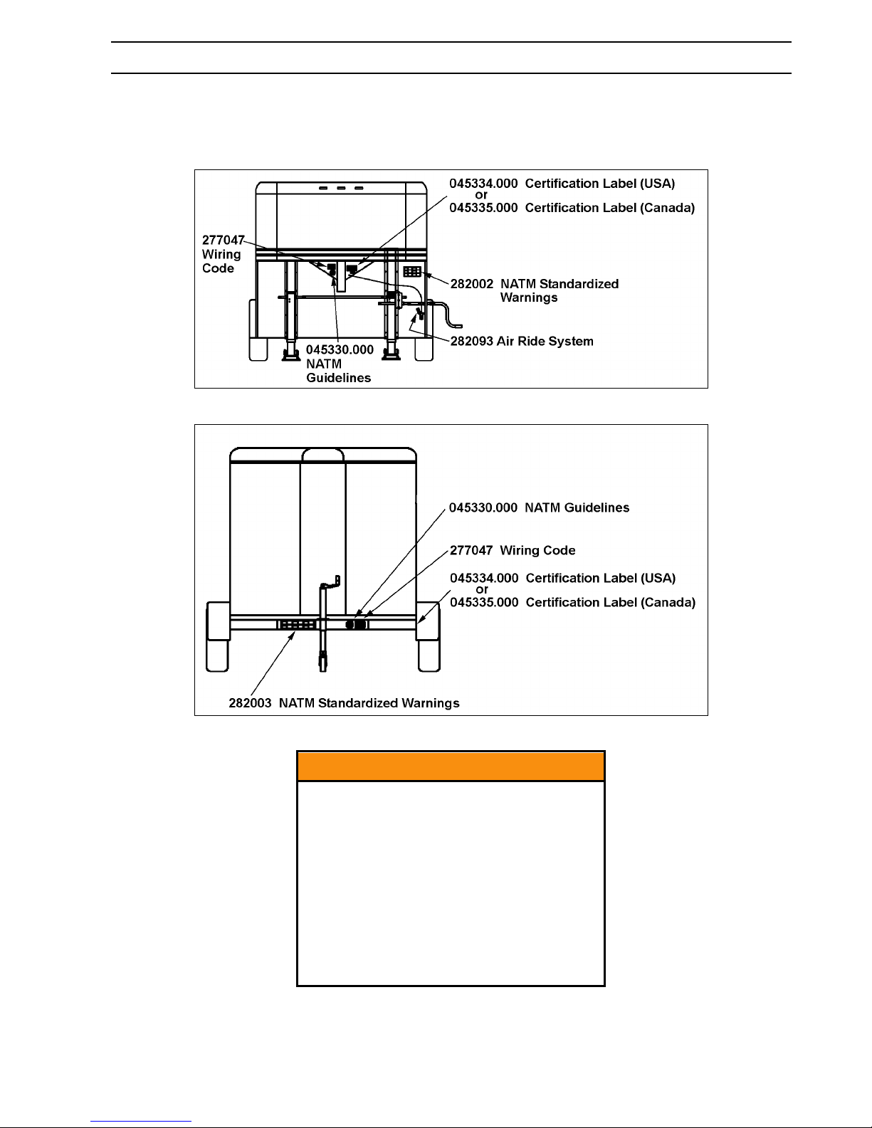
1.2.23 Safety Warning Labels on Your Trailer
Warning Labels and Locations – Gooseneck Trailer – Figure 1-2
Warning Labels and Locations – Bumper Pull Trailer – Figure 1-3
R6 3/30/2017 Page 11
To protect you and others aga inst death or
serious injury, all of the labels shown
above must be on the trailer and must be
legible.
If any of these safety labels are missing or
cannot be read, call Featherlite, Inc. at 800800-1230 for free replacement labels.
You will need to provide us with the
number shown at the bottom of the label (s)
in order for us to send the correct one(s).

Section 1 – Safety Information
1.2.24 Reporting Safety Defects
If you believe that your vehicle has a defect that
could cause a crash or could cau se injury or death,
you should immediately inform the National
Highway Traffic Safety Administration (NHTSA)
in addition to notifying us.
If NHTSA receives similar complaints, it may open
an investigation, and if it finds that a safety defect
exists in a group of vehicles, it may order a recall
and remedy campaign. However, N HTS A cann ot
become involved in individual problems between
you, your dealer, or us.
To contact NHTSA, you may either call the Vehicle
Safety Hotline toll-free at 1-888-327-4236 (TTY:1800-424-9153), go to http://www.safercar.gov, or
write to: Administrator, NHTSA, 1200 New Jersey
Ave., SE, Washington, DC 20590.
You can also obtain other information about motor
vehicle safety from http://www.safercar.gov.
Call 800-800-1230 to reach Featherlite, Inc.
R6 3/30/2017 Page 12

2 TIRE SAFETY INFORMATION
This portion of the User’s Manual contains tire
safety information as required by 49 CFR 575.6.
Section 2.1 contains “Trailer Tire Information”
Section 2.2 contains “Steps for Determining Correct
Load Limit - Trailer”.
Section 2.3 contains “Steps for Determining Correct
Load Limit – Tow Vehicle”.
Section 2.4 contains a Glossary of Tire
Terminology, including “cold inflation p ressure”,
“maximum inflation pressure”, “recommended
inflation pressure”, and other non-technical terms.
Section 2.5 contains information from the NHTSA
brochure entitled “Tire Safety – Everything Rides
On It”.
This brochure, as well as the preceding s ubsect ions,
describes the following items;
• Tire labeling, including a description and
explanation of each marking on th e tires, and
information about the DOT Tire Identification
Number (TIN).
• Recommended tire inflation pressure, including
a description and explanation of:
• Cold inflation pressure.
• Vehicle Placard and location on the
vehicle.
• Adverse safety consequences of under
inflation (including tire failure).
• Measuring and adjusting air pressure for
proper inflation.
• Tire Care, including maintenance and safety
practices.
• Vehicle load limits, including a description and
explanation of the following items:
• Locating and understandin g the load limit
information, total load capacity, and cargo
capacity.
• Calculating total and cargo capacities with
varying seating configurations including
quantitative examples showing / illustrating
how the vehicles cargo and luggage
capacity decreases as combined number
and size of occupants’ increases. This item
is also discussed in Section 3.
• Determining compatibility of tire and
vehicle load capabilities.
• Adverse safety consequences of
overloading on handling and stopping on
tires.
2.1 TRAILER TIRE INFORMATION
Trailer tires may be worn out even though they still
have plenty of tread left. This is because trailer
tires have to carry a lot of weight all the time, even
when not in use. It is actually better for the tire to
be rolling down the road than to be idle. During
use, the tire releases lubricants that are beneficial to
tire life. Using the trailer tires often also helps
prevent flat spots from developing.
The main cause of tire failure is improper inflation.
Check the cold tire inflation pressures at least once
a week for proper inflation levels. “Cold” means
that the tires are at the same temperature as the
surrounding air, such as when the vehicle has been
parked overnight. Wheel and tire manu facturers
recommend adjusting the air p ressu re to the trailer
manufacturer’s
pressure, in
the vehicle’s Federal Certification Label or Tire
Placard when the trailer is loaded to its gross
vehicle weight rating (GVWR). If the tires are
inflated to less than the recommended inflation
level or the GVWR of the trailer is exceeded, the
load carrying capacity of the tire could be
dramatically affected. If the tires are inflated more
than the recommended inflation level, handling
characteristics of the tow vehicle/trailer
combination could be affected. Refer to the
owner’s manual or talk to your dealer or vehicle
manufacturer if you have any questions regarding
proper inflation practices.
Tires can lose air over a period of time. In fact, tires
can lose 1 to 3 PSI per month. This is because
molecules of air, under pressure, weave their way
from the inside of the tire, through the rubber, t o the
outside. A drop in tire pressure could cause the tire
to become overloaded, leading to excessive heat
build up. If a trailer tire is under-inflated, even for
a short period of time, the tire could suffer internal
damage.
recommended cold inflation
pounds per squa re inc h (PS I ) stated on
R6 3/30/2017 Page 13

Section 2 - Tire Safety Information
High speed towing in hot conditions degrades
trailer tires significantly. As heat builds up during
driving, the tire’s internal structure starts to
breakdown, compromising the strength of the tire.
It is recommended to drive at moderate speeds.
Statistics indicate the average life of a trailer tire is
about five years under normal use and maintenance
conditions. After three years, replacing the trailer
tires with new ones shoul d be considered, even if
the tires have adequate tread depth . Some experts
claim that after five years, trailer tires are
considered worn out and should be re placed, even if
they have had minimal or no u se. This is such a
general statement that it may not apply in all cases.
It is best to have your tires inspected by a tire
supplier to determine if your tires need to be
replaced.
If you are storing your trailer for an extended
period, make sure the tires are fully inflated to the
maximum rated pressure and that you store them in
a cool, dry place, such as a garage. Use tire covers
to protect the trailer tires from the harsh effects of
the sun.
2.2 STEPS FOR DETERMINING CORRECT
LOAD LIMIT – TRAILER
Determining the load limits of a trailer includes
more than understanding the load limits of the tires
alone. On all trailers there is a Federal Certification
/ VIN label that is located on the forward half of the
left (road) side of the unit. This certification/VIN
label will indicate the trailer’s Gross Vehicle
Weight Rating (GVWR ). This is the most weight
the fully loaded trailer can weigh. It will also
provide the Gross Ax le Weight Rating (GAWR).
This is the most a particular axle can weigh. If there
are multiple axles, the GAWR of each axle will be
provided.
If your trailer has a GVWR of 10,000 pounds or
less, there is a vehicle placard located in the same
location as the certification label described above.
This placard provides tire and loading information.
In addition, this placard will show a statement
regarding maximum cargo capacity. Cargo can be
added to the trailer, up to the maximum weight
specified on the placard . The combined weight of
the cargo is provided as a single number. In any
case, remember: the total weight of a fully loaded
trailer can not exceed the stated GVWR.
For trailers with living quarters instal led, t he we ight
of water and propane also n eed to be considered.
The weight of fully filled propane containers is
considered part of the weight of the trailer before it
is loaded with cargo, and is not
the disposable cargo load. Water however, is a
disposable cargo weight and is treated as such. If
there is a fresh water storage tank of 100 gallons,
this tank when filled would weigh about 800
pounds. If more cargo is being transp orted, water
can be off-loaded to keep the total amount of cargo
added to the vehicle within the limits of the GVWR
so as not to overload the vehicle. Understanding
this flexibility will allow you, the owner, to make
choices that fit your travel needs.
When loading your cargo, be sure it is distributed
evenly to prevent overloading front to bac k and side
to side. Heavy items should be p laced low and as
close to the axle positions as reasonable. Too many
items on one side may overload a tire. The best way
to know the actual weight of the vehicle is to weigh
it at a public scale. Talk to your dealer to discu ss
the weighi ng methods nee ded to c apt ure the v ari ous
weights related to the trailer. This would include the
weight empty or unloaded, weights per axle, wheel,
hitch or king-pin, and total weight.
Excessive loads and/or underinflation cause tire
overloading and, as a result, abnormal tire flexing
occurs. This situation can generate an excessive
amount of heat within the tire. Excessive heat may
lead to tire failure. It is the air pressure that enables
a tire to support the load, so proper inflation is
critical. The proper air pressu re may be found on
the Certification / VIN label and/or on the Tire
Placard. This value should never exceed the
maximum cold inflation pressure stamped on the
tire.
considered p art of
R6 3/30/2017 Page 14
Section 2 - Tire Safety Information
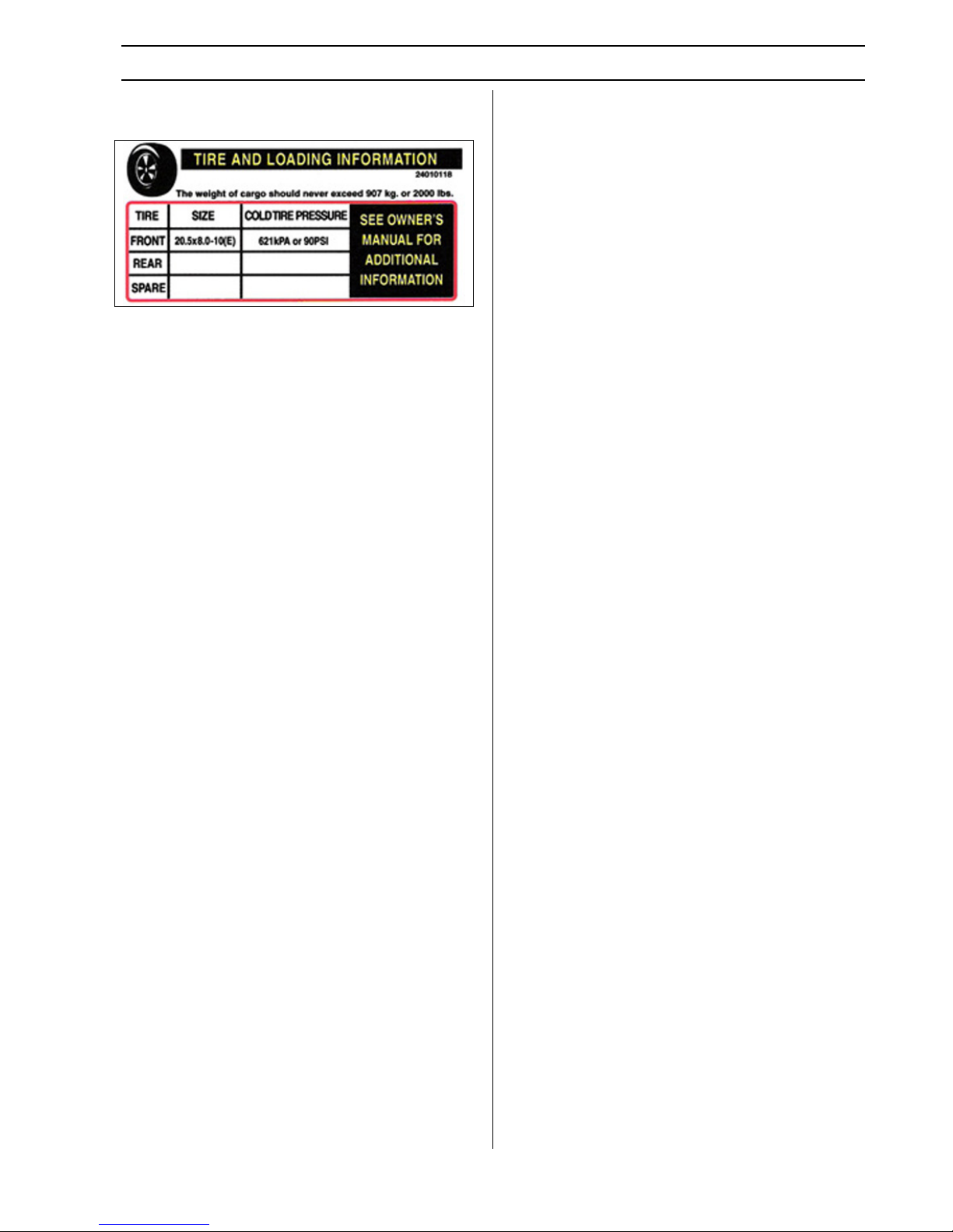
2.2.1 Trailers 10,000 Pounds GVWR or
Less
Tire Information Placard – Figure 2-1
1. Locate the statement, “The weight of cargo
should never exceed XXX kg or XXX lbs.,” on
your vehicle’s placard. See figure 2-1.
2. This figure equals the available amount of
cargo and luggage load capacity.
3. Determine the combined weight of lugg age and
cargo being loaded on the vehicle. That weight
may not safely exceed the available cargo and
luggage load capacity.
The trailer’s placard refers to the Tire Information
Placard attached adjacent to or near the trailer’s
VIN (Certification) label at the left front of the
trailer.
2.2.2 Trailers Over 10,000 Pounds GVWR
Note: These trailers are not required to h ave a tire
information placard on the trailer and may not have
one installed.
1. Determine the empty weight of your trailer by
weighing the trailer using a public scale or
other means. This step does not have to be
repeated.
2. Locate the GVWR (Gross Vehicle Weight
Rating) of the trailer on your trailer’s VIN
(Certification) label.
3. Subtract the empty weight of your trailer from
the GVWR stated on the VIN label. That
weight is the maximum available cargo
capacity of the trailer and may not be safely
exceeded.
2.3 STEPS FOR DETERMINING CORRECT
LOAD LIMIT – TOW VEHICLE
1. Locate the statement, “The combined weight of
occupants and cargo should never exceed X XX
lbs.,” on your vehicle’s placard.
2. Determine the combined weight of the d river
and passengers who will be riding in your
vehicle.
3. Subtract the combined weight of the driver and
passengers from XXX kilograms or XXX
pounds.
4. The resulting figure equals the available
amount of cargo and luggage capacity. For
example, if the “XXX” amount equals 1400
lbs. and ther e wi ll be fiv e 150 l b. pa sse nger s i n
your vehicle, the amount of available cargo an d
luggage capacity is 650 lbs. (1400-750 (5 x
150) = 650 lbs.).
5. Determine the combined weight of lugg age and
cargo being loaded on the vehicle. That weight
may not safely exceed the available cargo and
luggage capacity calculated in Step # 4.
6. If your vehicle will be towing a trailer, load
from your trailer will be transferred to your
vehicle. Consult the tow vehicle’ s manual to
determine how this weight transfer reduces the
available cargo and luggage capacity of your
vehicle.
2.4 GLOSSARY OF TIRE TERMINOLOGY
Accessory weigh t
The combined weight (in ex cess of those standard
items which may be replaced) of automatic
transmission, power steering, power brakes, power
windows, power seats, radio and heater, to the
extent that these items are available as factoryinstalled equipment (whether installed or not).
Bead
The part of the tire that is made of steel wires,
wrapped or reinforced by ply cords and that is
shaped to fit the rim.
Bead separatio n
This is the breakdown of the bond between
components in the bead.
Bias ply tire
A pneumatic tire in which the ply cords that extend
to the beads are laid at alternate angles substanti ally
less than 90 degrees to the centerline of the tread.
Carcass
The tire structure, except tread and sidewall rubber
which, when inflated, bears the load.
Chunking
The breaking away of pieces of the tread or
sidewall.
R6 3/30/2017 Page 15

Section 2 - Tire Safety Information
Cold inflation pressure
The pressure in the tire before you drive.
Cord
The strands forming the plies in the tire.
Cord separatio n
The parting of cords from adjacent rubber
compounds.
Cracking
Any parting within the tread, sidewall, or inner liner
of the tire extending to cord material.
CT
A pneumatic tire with an inverted flange tire and
rim system in which the rim is designed with rim
flanges pointed radially inward and the tire is
designed to fit on the underside of the rim in a
manner that encloses the rim flanges inside the air
cavity of the tire.
Curb weight
The weight of a motor vehicle with standard
equipment inc luding the maxi mum cap aci ty of f uel ,
oil, and coolant, and, if so equipped, air
conditioning and additional weight optiona l engi ne.
Extra load tire
A tire designed to operate at high er loads and at
higher inflation pressures th an the corresponding
standard tire.
Groove
The space between two adjacent tread ribs.
Gross Axle Weight Ra ting
The maximum weig ht tha t an y axle can s upport , as
published on the Certification / VIN label on the
front left side of the trailer. Actual weight
determined by weighing each axle on a public scale,
with the trailer attached to the towing vehicle.
Gross Vehicle Weight R ating
The maximum weight of the fully loaded trailer, as
published on the Certification / VIN label. A ctual
weight determined by weighing trailer on a public
scale, without being attached to the towing vehicle.
Hitch Weight
The downward force exerted on the hitch ball by
the trailer coupler.
Innerliner
The layer(s) forming the inside surface of a tubel ess
tire that contains the inflating medium within the
tire.
Innerliner separatio n
The parting of the innerliner from cord material in
the carcass.
Intended outboard sidewall
The sidewall that contains a white-wall, bears white
lettering or bears manufac turer, bra nd, and/or m odel
name molding that is higher or deeper than the
same molding on the other sidewall of the tire or t he
outward facing sidewall of an asymmetrical tire that
has a particular side that must always face outward
when mounted on a vehicle.
Light truck (LT) tire
A tire designated by its manufacturer as primarily
intended for use on lightweight trucks or
multipurpose passenger vehicles. May be used on
trailers.
Load rating
The maxim um l oa d t hat a tire is rated to carry for a
given inflation pressure.
Maximum load rating
The load rating for a tire at the maximum
permissible inflation pressure for that tire.
Maximum permissible inflation pressure
The maximum cold inflation pressure to which a
tire may be inflated.
Maximum loaded vehicle w eight
The sum of curb weight, accessory weight, vehicle
capacity weight, and production options weight.
Measuring rim
The rim on which a tire is fitted for physical
dimension requirements.
Non-pneumatic rim
A mechanical device which, when a non-pneumatic
tire assembly incorporates a wheel, supports the
tire, and attaches, eith er integrally or separably, to
the wheel center membe r and upon whi ch the ti re i s
attached.
R6 3/30/2017 Page 16

Section 2 - Tire Safety Information
Non-pneumatic sp are tire assembly
A non-pneumatic tire assembly intended for
temporary use in place of one of the pneumatic tires
and rims that are fitted to a passenger car in
compliance with the requirements of this standard.
Non-pneumatic tire
A mechanical device which transmits, either
directly or through a wheel or wheel center
member, the vertical load and tractive forces from
the roadway to the vehicle, generates the tractive
forces that provide the directional control of the
vehicle and does not rely on the containment of any
gas or fluid for providing those functions.
Non-pneumatic tire assembly
A non-pneumatic tire, alone or in combination with
a wheel or wheel center member, which can be
mounted on a vehicle.
Normal occupant weight
This means 68 kilograms (150 lbs.) times the
number of occupants specified in the second
column of Table I of 49 CFR 571.110.
Occupant distribution
The distribution of occupants in a vehicle as
specified in the third column of Tab le I of 49 CFR
571.110.
Open splice
Any parting at any junction of tread, sidewall, or
innerliner that extends to cord material.
Outer diameter
The overall diameter of an inflated new tire.
Overall width
The linear distance between the exteriors of the
sidewalls of an inflated tire, including elevations
due to labe ling, decorations, or protective bands or
ribs.
Pin Weight
The downward force applied to the 5
th
wheel or
gooseneck ball, by the trailer kingpin or gooseneck
coupler.
Ply
A layer of rubber-coated parallel cords.
Ply separation
A parting of rubber compound between adjacent
plies.
Pneumtic tire
A mechanical device made of ru bber, chemicals,
fabric and steel or other materials, that, when
mounted on an automotive wheel, provides the
traction and contains th e gas or fluid that sustains
the load.
Production options weight
The combined weight of those installed regular
production options weighing over 2.3 kilograms (5
lbs.) in excess of those standard items which they
replace, not previously considered in curb we ight or
accessory weight, including heavy duty brakes, ride
levelers, roof rack, heavy duty battery, and special
trim.
Radial ply tire
A pneumatic tire in which the ply cords that extend
to the beads are laid at substan tially 90 degrees to
the centerline of the tread.
Recommended inflation pressure
This is the inflation pressure provided by the
vehicle manufacturer on the Tire Information label
and on the Certification / VIN tag.
Reinforced tire
A tire designed to operate at higher loads and at
higher inflation pressures th an the corresponding
standard tire.
Rim
A metal support for a tire or a tire and tube
assembly upon which the tire beads are seated .
Rim diameter
This means the nominal diameter of th e bead seat.
Rim size designation
This means the rim diameter and width.
Rim type designation
This means the industry of manufacturer’s
designation for a rim by style or code.
Rim width
This means the nominal distance between rim
flanges.
R6 3/30/2017 Page 17

Section 2 - Tire Safety Information
Section width
The linear distance between the exteriors of the
sidewalls of an inflated tire, exclud ing elevations
due to labeling, decoration, or protective bands.
Sidewall
That portion of a tire between th e tread and bead.
Sidewall separation
The parting o f the rubber com po und from the co r d
material in the sidewall.
Special Trailer (ST) tire
The "ST" is an indication the tire is for trailer use
only.
Test rim
The rim on which a tire is fitted for testing, and m ay
be any rim listed as appropriate for use with th at
tire.
Tread
That portion of a tire th at comes into contact with
the road.
Tread rib
A tread section running circumferentially around a
tire.
Tread separatio n
Pulling away of the tread from the tire carcass.
Treadwear in dicators (TWI)
The projections within the principal grooves
designed to give a visual indication of the degrees
of wear of the tread.
Vehicle capacity weight
The rated cargo and luggage load plus 68 kilogr ams
(150 lbs.) times the vehicle’s designated seating
capacity.
Vehicle maximum load on the tire
The load on an individual tire that is determined by
distributing to each axle its sh are of the maximum
loaded vehicle weight and dividing by two.
Vehicle normal load on the tire
The load on an individual tire that is determined by
distributing to each axle its share of the curb
weight, accessory weight, and normal occupant
weight (distributed in accordance with Tab le I of
CRF 49 571.110) and dividing by 2.
Weather side
The surface area of the rim not covered by the
inflated tire.
Wheel center memb er
In the case of a non-pneumatic tire assembly
incorporating a wheel, a mech anical device wh ich
attaches, either integrally or separably, to the nonpneumatic rim and provides the connection between
the non-pneumatic rim and the vehicle; or, in the
case of a non-pneumatic tire assembly not
incorporating a wheel, a mechanical d evice which
attaches, either integrally or separably, to the nonpneumatic tire and provides the connection between
tire and the vehicle.
Wheel-holding fixture
The fixture used to hold the wheel and tire
assembly securely during testing.
2.5 TIRE SAFETY - EVERYTHING RIDES ON
IT
The National Traffic Safety Administration
(NHTSA) has publis h e d a br ochure (DOT HS 809
361) that discusses all aspects of Tire Safety, as
required by CFR 575.6. This brochure is
reproduced in part below. It can be obtained and
downloaded from NHTSA, free of charge, from the
following web site:
http://www.nhtsa.dot.gov/cars/rules/TireSafety/rides
onit/tires_index.html
Studies of tire safety show that maintaining proper
tire pressure, observing tire and vehicle load limits
(not carrying more weight in your vehicle than y our
tires or vehicle can safely handle), avoidi ng road
hazards, and inspecting tires for cuts, slash es, and
other irregularities are the most important things
you can do to avoid tire failure, such as tread
separation or blowout and flat tires. These actions,
along with other care and maintenance activities,
can also:
• Improve vehicle handling
• Help protect you and others from avoidable
breakdowns and accidents
• Improve fuel economy
• Increase the life of your tires.
This booklet presents a comprehensive overview o f
tire safety, including information on the following
topics:
R6 3/30/2017 Page 18

Section 2 - Tire Safety Information
• Basic tire maintenance
• Uniform Tire Quality Grading System
• Fundamental characteri stics of tir es
• Tire safety tips.
Use this information to make tire safety a regular
part of your vehicle maintenance routine. Recognize
that the time you spend is minimal compared with
the inconvenience and safety consequences of a flat
tire or other tire failure.
2.5.1 Safety First–Basic Tire Maintenance
Properly maintained tires improve the steering,
stopping, traction, and load-carrying capability of
your vehicle. Underinflated tires and overloaded
vehicles are a major cause of tire failure. Therefore,
as mentioned above, to avoid flat tires and other
types of tire failure, you should maintain proper tir e
pressure, observe tire and vehicle load limits, avoid
road hazards, and regular ly inspect your tires.
2.5.2 Finding Your Vehicle's
Recommended Tire Pressure and
Load Limits
Tire information placards and vehicle certification
labels contain information on tires and load limits.
These labels indicate the vehicle manufacturer's
information including:
• Recommended tire size
• Recommended tire inflation pressure
• Vehicle capacity weight (VCW–the maximum
occupant and cargo weight a vehicle is
designed to carry)
• Front and rear gross axle weight ratings
(GAWR– the maximum weight the axle
systems are designed to carry).
Both placards and certification labels are
permanently attached to the trailer near the left
front.
2.5.3 Understanding Tire Pressure and
Load Limits
Tire inflation pressure is the level of air in th e tire
that provides it with load-carrying capacity and
affects the overall performance of the vehicle. The
tire inflation pressure is a number that indicates the
amount of air pressure– measured in pounds per
square inch (psi)–a tire requires to be properly
inflated. (You will also find this number on the
vehicle information placard expressed in kilopascals
(kPa), which is the metric measure used
internationally.)
Manufacturers of passenger vehicles and light
trucks de termi ne this num ber base d on the ve hic le 's
design load limit, that is, the greatest amount of
weight a vehicle can safely carry and the vehicle's
tire size. The proper tire pressure for your vehicle
is referred to as the "recommended cold inflation
pressure." (As you will read below, it is difficult to
obtain the recommended tire pressure if your tires
are not cold.)
Because tires are designed to be used on more than
one type of vehicle, tire manufacturers list the
"maximum permissible inflation pressure" on the
tire sidewall. This number is the greatest amount of
air pressure that should ever be put in the tire under
normal driving conditions.
2.5.4 Checking Tire Pressure
It is important to check your vehicle's tire pressure
at least once a month for the following reasons:
• Most tires may naturally lose air over time.
• Tires can lose air sudd enly if you drive over a
pothole or other object or if you strike the curb
when parking.
• With radial tires, it is usually not possible to
determine underinflation by visual inspection.
For convenience, purchase a tire pressure gauge to
keep in your vehicle. Gauges can be purch ased at
tire dealerships, auto supply stores, and other retail
outlets.
The recommended tire inflation pressure that
vehicle manufacturers provid e reflects the proper
psi when a tire is cold. The term cold does not r elat e
to the outside temperature. Rather, a cold tire is one
that has not been driven on for at least three hours.
When you drive, your tires get warmer, causing the
air pressure within them to increase. Therefore, to
get an accurate tire pressure reading, you must
measure tire pressure when the tires are cold or
compensate for the extra pressure in warm tires.
2.5.5 Steps for Maintaining Proper Tire
Pressure
• Step 1: Locate the recommended ti re pressure
on the vehicle's tire information placard,
certification label, or in the owner's manual.
• Step 2: Record the tire pressure of all tires.
• Step 3: If the tire pressure is too high in any of
the tires, slowly release air by gently pressing
R6 3/30/2017 Page 19

Section 2 - Tire Safety Information
on the tire valve stem with the edge of your tire
gauge until you get to the correct pressure.
• Step 4: If the tire p ressure is too low, n ote the
difference between the measur ed tire pressure
and the correct tire p ressure. These "missing"
pounds of pressure are what you will need to
add.
• Step 5: At a service station , add the missing
pounds of air pressure to each tire that is
underinflated.
• Step 6: Ch eck all the tires to make sure they
have the same air pressure (excep t in cases in
which the front and rear tires are supp osed to
have different amounts of pressu re).
If y ou have be en drivi ng yo ur vehic le and t hink t hat
a tire is underinflated, fill it to the recommended
cold inflation pressure indicated on your vehicle's
tire information placard or certification label. While
your tire may still be slightly underinflated d ue to
the extra pounds of p ressure in th e warm tire, it is
safer to drive with air pressure that is slightly lower
than the vehicle manufacturer's recommended cold
inflation pressure than to drive with a significantly
underinflated tire. Since this is a temporary fix,
don't forget to recheck and adjust the tire's pressure
when you can obtain a cold reading.
2.5.6 Tire Size
To maintain tire safety, purchase new tires that are
the same size as the vehicle's original tires or
another size recommended by the manufacturer.
Look at the tire information placard, the owner's
manual, or the sidewall of the tire you are replacing
to find this information. If you have any doubt
about the correct size to choose, consu lt with the
tire dealer.
you can see the top of Lincoln's head, you are ready
for new tires.
2.5.8 Tire Balance and Wheel Al ignment
To avoid vibration or shaking of the vehicle when a
tire rotates, the tire must be properly balanced. This
balance is achieved by positioning weights on the
wheel to counterbalance heavy spots on the wheeland-tire assembly. A wheel alignment adjusts the
angles of the wheels so that they are positioned
correctly relative to the vehicle's frame. This
adjustment maximizes the life of your tires. Th ese
adjustments require special equipment and should
be performed by a qualified technici an.
2.5.9 Tire Repair
The proper repair of a punctured tire requir es a plug
for the hole and a patch for the area inside th e tire
that surrounds the puncture hole. Punctures through
the tread can be repaired if t hey are not too large,
but punctures to the sidewall should not be
repaired. Tires must be removed from the rim to be
properly inspected before being plugged and
patched.
2.5.10 Tire Fundamentals
Federal law requires tire manufacturers to place
standardized information on the sidewall of all tires.
This information identifies and describes the
fundamental characteristics of the tire and also
provides a tire identification number for safety
standard certification and in case of a recall.
2.5.10.a Information on Passenger Vehicle Tires
Please refer to the diagram below.
2.5.7 Tire Tread
The tire tread provides the gripping action and
traction that prevent your vehicle from slipping or
sliding, especially when the road is wet or icy. In
general, tires are not safe and shou ld be replaced
when the tread is worn down to 1/16 of an inch.
Tires have built-in treadwear indicators that let you
know when it is time to replace your tires. These
indicators are raised sections spaced intermitten tly
in the bottom of the tread grooves. When they
appear "even" with th e outside of the tread, it is
time to replace your tires. Another method for
checking tread depth is to place a penny in the tread
with Linc oln' s head ups ide dow n and fa cing y ou. If
R6 3/30/2017 Page 20

Section 2 - Tire Safety Information
P
The "P" indicates the tire is for passenger vehicles.
Next number
This three-digit number gives the width in
millimeters of the tire from sidewall edge to
sidewall edge. In general, the larger the number, the
wider the tire.
Next number
This two-digit number, known as the aspect ratio,
gives the tire's ratio of height to width. Numbers of
70 or lower indicate a short sidewall for improved
steering response and better overall handling on dry
pavement.
R
The "R" stands for radial. Radial ply construction of
tires has been the indu stry standard for the past 20
years.
Next number
This two-digit number is the wheel or rim diameter
in inches. If you chan ge your wheel size, you will
have to purchase new tires to match the new wheel
diameter.
Next number
This two- or three-digit number is the tire's load
index. It is a measurement of how much weight
each tire can support. You may find this
information in your owner's manual. If not, contact
a local tire dealer. Note: You may not find this
information on all tires because it is not required by
law.
M+S
The "M+S" or "M/S" indicates that the tire has
some mud and snow capability. Most radial tires
have these markings; hence, they have some mud
and snow capability.
Speed Rating
The speed rating denotes the speed at which a tire
is designed to be driven for extended periods of
time. Note: You may not find this information on
all tires because it is not required by law.
U.S. DOT Tire Identification Number
This begins with the letters "DOT" an d indicates
that the tire meets all federal standards. The next
two numbers or letters are the plant code where it
was manufactured, and the last four numbers
represent the week and year the tire was built. For
example, the numbers 3197 means the 31st week
of 1997. The other numbers are marketing codes
used at the manufacturer's discretion . This
information is used to contact consumers if a tire
defect requires a recall.
Tire Ply Composition and Materials Used
The number of plies indicates the number of
layers of rubber-coated fabric in the tire. In
general, the greater the number of plies, the more
weight a tire can support. Ti re man ufacturers also
must indicate the materials in the tire, which
include steel, nylon, polyester, and others.
Maximum Load Rating
This number indicates the maximum load in
kilograms and pound s that can be carried by the
tire.
Maximum Permissible Inflation Pressure
This number is the greatest amoun t of air p ressu re
that should ever be put in the tire under normal
driving conditions.
2.5.10.b UTQGS Information
Treadwear Number
This number indicates the tire's wear rate. The
higher the treadwear number is, the longer it should
take for the tread to wear down. For example, a tire
graded 400 sho uld last twice as long as a t ire g rad ed
200.
Traction Letter
This letter indicates a tire's ability to stop on wet
pavement. A higher graded tire should allow you to
stop your car on wet roads in a shorter distance tha n
a tire with a lower grade. Traction is graded from
highest to lowest as "AA","A", " B ", and "C".
Temperature Letter
This letter indicates a tire's resistance to h eat. The
temperature grade is for a tire that is inflated
properly and not overloaded. Excessive speed,
underinflation or excessive loading, either
separately or in combination, can cause heat buildup and possible tire failure. From highest to lowest,
a tire's resistance to heat is graded as "A", "B", or
"C".
2.5.10.c Information on Light Truck (LT) Tires
Please refer to the following diagram.
R6 3/30/2017 Page 21

Section 2 - Tire Safety Information
Tires for light trucks have other markings besides
those found on the sidewalls of passenger tires.
LT
The "LT" indicates the tire is for light trucks or
trailers.
Max. Load Dual kg (lbs) at kPa (psi) Cold
This information indicates the maximum load and
tire pressure when the tire is used as a dual, that is,
when four tires are put on each rear axle (a total of
six or more tires on the vehicle).
Max. Load Single kg (lbs) at kPa (psi) Cold
This information indicates the maximum load and
tire pressure when the tire is used as a single.
Load Range
This information identifies the tire's load-carrying
capabilities and its inflation limits.
2.5.10.d Information on Special Trailer (ST)
Tires
Please refer to the following diagram.
Tires designated for trailers only have other
markings besides those foun d on the sidewalls of
passenger tires.
ST
An "ST" is an indication the tire is for trailer use
only. “ST” tires are design for carrying heavy loads
at lower speeds.
The Tire and Rim Association Standard in dicates
that for operation at speeds up to 65 mph, no
change in maximum cold tire inflation pressure or
load is required. Recommended speed may vary and
the owner should check ratings for the specific tire
installed on the trailer.
Max. Load Dual kg (lbs) at kPa (psi) Cold
This information indicates the maximum load and
tire pressure when the tire is used as a dual, that is,
when four tires are put on each rear axle (a total of
six or more tires on the vehicle).
Max. Load Single kg (lbs) at kPa (psi) Cold
This information indicates the maximum load and
tire pressure when the tire is used as a single.
Load Range
This information identifies the tire's load-carrying
capabilities and its inflation limits.
R6 3/30/2017 Page 22
2.5.11 Tire Safety Tips
Preventing Tire Damage
• Slow down if you have to go over a pothole or
other object in the road.

Section 2 - Tire Safety Information
• Do not run over curb s or other foreign obj ects
in the roadway, and try not to strike the curb
when parking.
Tire Safety Checklist
• Check tire pressure regularly (at least once a
month), including the spare.
• Inspect tires for uneven wear p atterns on the
tread, cracks, foreign objects, or other signs of
wear or trauma.
• Remove bits of glass and foreign objects
wedged in the tread.
• Make sure your tire valves have valve caps.
• Check tire pressure before going on a long trip.
• Do not overload your vehicle. Check the tire
information placard or owner’s manual for the
maximum recommended load for the vehicle.
R6 3/30/2017 Page 23

^ DANGER
3 COUPLING TO THE TOW VEHICLE
This manual provides instructions for the operation
and care of Featherlite Horse, Livestock, and
Enclosed Trailers. Th e instructions in the manual
must be followed to ensure safety of perso ns, hor ses
and livestock, and satisfactory life of the trailer.
Safety precautions to protect against injury or
property damage must be followed at all times.
This section of the manual is organized into the
following subsections:
• Using an adequ ate tow veh icle and hitch
• Coupling the trailer to the tow vehicle
• Loading the trailer
• Checking the trailer for safety before each tow
• Breaking in a new trailer
• Synchronizing the brakes
• Uncoupling the trailer
Trailer Accessories
Featherlite offers trailers with a wide range of
accessories. Instructions for safe use of these
accessories are located in separate instruction
manuals, some of which are provided by the
accessory manufacturer.
Section 7 of this manual contains instructions
regarding the use of some accessory items, such as:
• Gasoline or diesel generators
• Accessory Battery
• “Shore Power” connection s to provide power
by “plugging the trailer in” to an external
source of electrical power
• LP (Liquid Petroleum Gas) facilities for heating
or other uses
• Electric-powered hydraulic landing gear
• Vending or Accessor y Doors
Your Featherlite trailer has been built using parts
from various component manuf acturer s. Where t his
manual indicates that you should read another
manual, and you do not have that manual, call
Featherlite at 1-800-800-1230 for assistance.
3.1 USE AN ADEQUATE TOW VEHICLE AND
HITCH
If the tow vehicle or hitch is not properly selected
and matched to the Gross Veh icle Weight Rating
(GVWR) of your trailer, you can cause an accident
that could lead to death or serious injury. Tow
vehicle and hitch manufacturers are the appropriate
source of competent advice.
If you already have a tow vehicle, know your
vehicle tow rating and make certain the trailer’s
rated capacity is less than or equal to the tow
vehicle’s rated towing capacity.
Use of an under-rated hitch, ball or tow
vehicle can result in l oss of control leading
to death or serious injury.
Make certain your hitch and tow vehicle
are rated for your trailer.
3.1.1 Trailer Information
The “Trailer Certification (VIN) Tag” location
figure shows the location of the Certification /
Vehicle Identification Number (VIN) tag on your
trailer. See figure 3-1 or 3-2.
Gooseneck Certification (VIN) Tag Location –
Figure 3-1
R6 3/30/2017 Page 24

Section 3 - Coupling To The Tow Vehicle
Bumper Pull Certification (VIN) Tag
Location – Figure 3-2
The trailer Certification (VIN) tag contains the
following critical safety information for the use of
your trailer:
MANUFACTURER: Name of trailer
manufacturer
DATE OF MANUFACTURE: Month and year
the trailer was manufactured.
GAWR: The Gross Axle Weight Rating is the
maximum gross weight that an axle can support. It
is the lowest of axle, wheel, or tire rating.
Sometimes the tire or wheel rating is lower than the
axle manufacturers rating, and will then determine
GAWR.
GVWR: The Gross Vehicle Weight Rating is the
maximum allowable gross weight of the trailer and
its contents. The gross weight of the trailer includes
the weight of the trailer and all of the items within it
(such as cargo, water, food and other supplies).
GVWR is sometimes referred to as GT W (Gross
Trailer Weight), or MGTW (Maximum Gross
Trailer Weight). GVWR, GTW and MGTW are a ll
the same rating.
The sum total of the GAWR for all trailer a xles may
be less than the GVWR for the trailer, because
some of the trailer load is carried by the tow
vehicle, rather than by the trailer axle(s). The total
weight of the cargo and trailer must not exceed
the GVWR, and the load on an axle must not
exceed its GAWR.
PSIC: The “pounds per square inch-cold” is the
tire pressure (Kilopascals / Pounds per Square I nch)
measured when Cold.
VIN: The Vehicle Identification Number.
VEHICLE TYPE: Trailer pl us the model number
of the trailer.
Certification Sta tement: “This trailer meets all
the Federal Motor Vehicle Safety Standards in
effect on the date of manufacture sh own above.”
There are two additional weights that are not
provided on the Certification (VIN) tag that are
importa nt, and that should be put som ew he re on t he
trailer. These are the “empty weight” and
“maximum cargo weight”.
The “empty weight” is sometimes put on the
Manufacturer’s Certificate of Origin (Title) but may
not be accurate for your particular trailer, due to
accessories, optional equipment, etc. The best way
to determine empty weight is to weigh the entire
trailer on a “Certified” scale at a truck stop. This
requires detaching the trailer and leaving the entire
trailer on the scale. Furth ermore, it is desirable to
weigh the tongue weight. This can be done by reattaching the trailer to the tow vehicle, after getting
the empty weight, and then just weighing the trailer
axles(s). Subtracting the axle weight from the
empty weight gives you the tongue weight.
Knowing the empty weight now allows you to
calculate the “maximum cargo weight”. Simply
subtract the empty weight from the GVWR shown
on the Certification / VIN tag.
While you’re at the scale it is also a good idea to
weigh the towing vehicle, with driver, in the typical
towing scenario. This will provide you with the
total “combination vehicle weight”, which can then
be compared to the allowable Gross Combined
Weight Rating (GCWR) provided by the tow
vehicle manufacturer, as discussed below.
3.1.2 Tow Vehicle
When equip ping a new vehicle or an old er vehicle
to tow your trailer, ask the vehicle dealer for advice
on how to outfit the towing vehicle. Discuss the
following information and equipment with the
vehicle dealer.
R6 3/30/2017 Page 25

Section 3 - Coupling To The Tow Vehicle
Overall Carrying and Towing Capacity of
Vehicle: Vehicle manufacturers will provide you
with the maximum towing capacities of their
various models, as well as the GCWR. No amount
of reinforcement will give a 100 horsepower, 2,500
pound truck the towing capacity that a 300
horsepower, 5,000 pound truck has.
Towing Hitch: The towing hitch attached to your
tow vehicle must have a capacity equal to or great er
than the load rating of the trailer you intend to tow.
The hitch capacity must also be matched to the tow
vehicle capacity.
Suspension System: A to w vehic le equippe d with
a factory installed “Towing Package” likely comes
equipped wit h hea vy duty s pri ngs , he av y dut y tires
and other suspension components which are able to
serve the size and weight of the trailer that the
vehicle is rated to tow. However, the addition of
additional equipment may further improve the tow
vehicle performance. These may include adjustable
air shocks, helper springs, et c.
Brake Controller: The brake controller is part of
the tow vehicle and is essential in the operation of
the electric brakes on the trailer. If your trailer has
electric brakes it requires a brake controller be
installed at the driver’s position. The brake
controller is not th e same as the safety breakaway
brake system that is installed on the trailer.
Side View Mirrors: T he size of the trailer th at is
being towed and your state law regulations
determine the size of the mirrors. However, some
states prohibit extend ed mirrors on a tow vehicle,
except while a trailer is actually being towed. In
this situation, detachable extended mirrors are
necessary. Check with your dealer or the
appropriate state agency for mirror requirements.
Heavy Duty Flasher : A Heavy Duty Flasher is an
electrical component that may be required when
your trailer turn signal lights are attached to the tow
vehicle flasher circuit.
Electrical Connector: An Electrical Connector
connects the light and brake systems on the trailer
to the light and brake controls on the towing
vehicle.
Heavy Duty Engine Oil Cooling System: The
tow vehicle engine works harder when a trailer is
being towed. Depending on the size of the trailer,
you may need to install a separate engine oil cooler.
Inadequate cooling may result in sudden engine
failure. Ask the tow vehicle dealer if it is necessary
to install a heavy duty cooling system.
Automatic Transmission Oil Cooler: The
automatic transmission of a towing vehicle handles
more power when a trailer is being towed.
Inadequate cooling will shorten transmission life,
and may result in sudden transmission failure. Ask
the tow vehicle dealer if it is necessary to install a
separate oil cooler for the automatic transmission.
Fire Extinguisher: It is sensible to have a fire
extinguisher in the tow vehicle.
Emergency Flares and Emergency Triangle
Reflectors: It is wise to carry these warning
devices even if you are not towing a trailer. It is
particularly important to have these when towing a
trailer because the hazard f lashers of your towing
vehicle will not operate for as long a period of time
when the battery is running both the trailer lights
and tow vehicle lights.
3.2 COUPLING AND UNCOUPLING THE
TRAILER
A secure coupling (or fastening) of the trailer to the
tow vehicle is essential. A loss of coupling may
result in death or serious injury. Therefore, you
must understand and follow all of the instructions
for coupling.
The following parts are involved in making a secure
coupling between the trailer and tow vehicle:
Coupling: That part of the trailer connecting
mechanism by which the connection is actually
made to the trailer hitch. This does not include any
structural member, extension of the trailer fram e, o r
brake controller. (per SAE J684)
Hitch: That part of the connecting mechanism
including the ball support platform and ball and
those components that extend and are attached to
the towing vehicle, including bumpers intended to
serve as hitches. (per SAE J684)
Safety chains: Chains are permanently attached to
the trailer such that if the coupler connection comes
loose, the safety chains can keep the trailer attac hed
to the tow vehicle. With properly rigged safety
R6 3/30/2017 Page 26

Section 3 - Coupling To The Tow Vehicle
^ WARNING
chains, it is possible to keep the tongue of the traile r
from digging into the road pavement, even if the
coupler-to-hitch connection comes apart.
Trailer lighting (and braking) connector: A
device that connects electrical power from the tow
vehicle to the trailer. Electricity is used to turn on
brake lights, running lights, and turn signals as
required. In addition, if your trailer has a separate
braking system, the electrical connector will also
supply power to the trailer brakes from the tow
vehicle.
Breakaway switch: If the trailer becomes decoupled from the towing vehicle, the breakaway
switch lanyard, attached indep endently to the tow
vehicle hitch, will pull a pin in the emergency
electrical breakaway switch on the trailer. The
breakaway switch is activated by a separate battery
supply in the trailer such as to energize the trailer
brakes independently of the towing vehicle. It is
important to check the state of charge of the
emergency breakaway battery before each trip.
Simply pull the pin out of the switch by hand and
then try to pull the trailer. If you feel a significant
drag force the brakes are activated. Be sure to reinsert the pin in the breakaway switch. Also be sure
to allow enough slack in the breakaway brake
lanyard such that the switch will only activate (pin
pulls out) if the coupler connection comes loose.
Jack: A device on the trailer that is used to raise
and lower the trailer tongue. On larger trailers the
jack is sometimes called the “landing gear.”
An improperly coupled trailer can result in
death or serious injury.
Do not move the trailer until:
• The coupler is secured and locked;
• The safety chains are secured to the
tow vehicle; and
• The trailer jacks are fully retracted.
• Do not tow the trailer on the road until:
• The trailer brakes are checked;
• The breakaway switch is con nect ed t o
the tow vehicle;
• The load is secured to the trailer; and
• The trailer lights are connected and
checked.
Couplers
Featherlite Trailers are produced with a variety of
coupler devices. One of the sections below will
pertain to your trailer.
• Bumper pull (Ball Hitch) Coupler
• Gooseneck Ball Hitch Coup ler
• Gooseneck Fifth Wheel Coupler
If you need information or assistance with your
coupler, call Featherlite, Inc. at 800-800-1230 or
your dealer.
3.2.1 Trailer with Ball Hitch Coupler
A ball hitch coupler connects to a ball that is
located on or under the rear bumper of the tow
vehicle. This system of coupling a trailer to a tow
vehicle is sometimes referred to as “bumper pull.”
A ball hitch trailer may be fitted with a tongue jack
that can raise and lower the coupler. The tongue
jack is mounted to th e A-frame (front, or tongue)
part of the trailer. By rotating the jack handle
clockwise, the jack will extend and raise the tongue
of the trailer. Figure 3-3 shows a trailer with a ball
hitch coupler.
R6 3/30/2017 Page 27

Section 3 - Coupling To The Tow Vehicle
^ WARNING
^ WARNING
^ WARNING
ball nut can result in
Trailer with Ball Hitch Coupler – Figure 3-3
Be sure the Ball Hitch coupler is suitable for the
size and weight of the trailer. The load rating of the
coupler and the necessary ball size are listed on the
trailer tongue. You must provide a h itch and ball
for your tow vehicle, where the load rating of the
hitch and ball is equal to or greater than that of your
trailer. Also, th e bal l size must b e the same as th e
coupler size. If the hitch ball is too small, too large,
is underrated, is loose or is worn, the trailer can
come loose from the tow vehicle, and may cause
death or serious injury.
THE TOW VEHICLE, HITCH AND BALL
MUST HAVE A RATED TOWING CAPACITY
EQUAL TO OR GREATER THAN THE
TRAILER Gross Vehicle Weight Rating (GVWR).
IT IS ESSENTIAL THAT THE HI TCH BALL BE
OF THE SAME SIZE AS THE COUPLER.
IF THE HITCH BALL IS TOO SMALL, IS
UNDERRATED, IS LOOSE OR IS WORN, THE
TRAILER CAN COME LOOSE FROM THE
TOW VEHICLE, RESULTING IN DEATH OR
SERIOUS INJURY.
The ball size and load rating (capacity) are marked
on the ball; hitch capacity is marked on the hitch.
3.2.1.a Befo re Coupling the Trailer to the Tow
Vehicle
• Be sure the size and ratin g of hitch b all match
the size and rating of the coupler. Hitch balls
and couplers are marked with their size and
rating.
Coupler-to-hitch mismatch can result in
uncoupling, leading to death or serious
injury.
Make sure the hitch and ball are rated for
the trailer coupling.
Make sure the hitch [ball size] matches the
coupler.
• Wipe the hitch ball clean and inspect it visually
and by feel for flat spots, cracks and pits.
A worn, crack ed or cor roded hi tch ball c an
fail while towing, and may res ult in de ath or
serious injury .
Check the hitch ball for wear, corros ion and
cracks before coupling the trailer.
Replace worn, corroded or cracked hitch
ball before coupling the trailer.
• Rock the ball to make sure it is tight to the
hitch, and visually check that the hitch ball nut
is solid against the lock washer and hi tch fram e.
• Wipe the inside and outside of the coupler
clean and inspect it visually for cracks and
deformations; feel the inside of the coupler for
worn spots and pits.
• Be sure the coupler is tight to the tongue of the
trailer. All coupler fasteners must b e visibly
solid against the trailer frame.
A loose hitch
uncoupling, leading to death or serious
injury.
Make sure the hitch ball is tight to the hitch
before coupling the trail er.
R6 3/30/2017 Page 28

Section 3 - Coupling To The Tow Vehicle
NOTICE
The tongue jack can be damaged by
3.2.1.b Prepare the Coupler and Hitch
• Lubricate the hitch ball and the in side of the
coupler with a thin layer of automotive bearing
grease. Using the jack, raise the coupler above
the ball height.
• The trailer can be equipp ed with two different
types of couplers. See figures 3-4, 3-5 and 3-6
to determine the type of coupler on your trailer.
• Open the coupler locking mechanism. Ball
couplers have a locking mechanism with an
internal moving piece (ball clamp) and an
outside handle, wheel, or latch. See figures 34, 3-5 and 3-6.
• In the open or unlatched position, the
coupler is able to drop fully onto the hitch
ball.
• See the coupler instructions for details of
placing the coupler in the open or
unlatched position.
• Slowly back up the tow vehicle so that the hitch
ball is near or aligned under the coupler, if the
trailer jack has raised the coupler.
Latched and Unlatched Position (Cequent) –
Figure 3-4
3.2.1.c Couple the Trailer to the Tow Vehicle
(Cequent Coupler)
• Using the jack, lower the trailer tongue until the
coupler fully engages the hitch ball. If the
coupler does not line up with the hitch ball,
adjust the position of the tow vehicle.
• Engage the coupler locking mechanism. I n the
engaged position, the locking mechanism
securely holds the coupler to the hitch ball.
• Insert a pin or lock through the hole in the
locking mechanism.
• Be sure the cou pler is all th e way on the hitch
ball and the locking mechanism is engaged. A
properly engaged locking mechanism will allow
the coupler to raise the rear of the tow vehicle.
Using the trailer jack, test to see that you can
raise the rear of the tow vehicle by 1 inch, after
the coupler is locked to the hitch.
overloading. Do not use the tongue ja ck to
raise the tow vehicle more than 1 inch.
If the coupler cannot be secured to the hitch
ball, do not to w the trailer. Call Featherlite, Inc.
at 800-800-1230 or your dealer for assistance.
• Lower the trailer so that its entire to ngue we ight
is held by the hitch, and continue retracting the
jack to its fully retracted position.
3.2.1.d Couple the Trailer to the Tow Vehicle
(Demco Coupler)
Latched and Unlatched Position (Demco) –
Figure 3-5
R6 3/30/2017 Page 29
• Using the jack, lower the trailer to ngue unt il the
coupler fully engages the hitch ball. If the
coupler does not line up with the hitch ball,
adjust the position of the tow vehicle.
• Lower the trailer to the ball (do not lift handle),
while the coupler is going over the ball the
handle will lift up automatically and lock over
ball as it is lowered.

Section 3 - Coupling To The Tow Vehicle
6
NOTICE
The tongue jack can be damaged by
Latched Position – Figure 3-6
• There is no need to insert a pin in to the hole
(A). With the handle down it is securely locked.
This hole is used for security only.
• Be sure the cou pler is all th e way on the hitch
ball and the locking mechanism is latch ed. A
properly engaged locking mechanism will allow
the coupler to raise the rear of the tow vehicle.
Using the trailer jack, test to see that you can
raise the rear of the tow vehicle by 1 inch, after
the coupler is locked to the hitch.
3.2.1.e Rig the Safety Chains
overloading. Do not use the tongue ja ck to
raise the tow vehicle more than 1 inch.
If the coupler cannot be secured to the hitch
ball, do not to w the trailer. Call Featherlite, Inc.
at 800-800-1230 or your dealer for assistance.
• Lower the trailer so that its entire to ngue we ight
is held by the hitch, and continue retracting the
jack to its fully retracted position.
Safety Chain Arrangement – Figure 3-7
• Visually inspect the safety chains and hoo ks fo r
wear or damage. Replace worn or damaged
safety chains and hooks before towing.
• Rig the safety chains so that they:
• Cris-cross underneath the coupler so if the
trailer uncouples, the safety chains can hold
the tongue up above t he road. See figure 3-
7.
• Loop around a frame member of th e tow
vehicle or to holes provided in the hitch
system (but, do not attach them to an
interchangeable part of the hitch assembly )
• Attach hooks up from unde r n e a t h the hole
(do not just drop into hole); an d
• Provide enough slack to permit tight turns,
but not be close to the road surface to drag.
R6 3/30/2017 Page 30

Section 3 - Coupling To The Tow Vehicle
^ WARNING
^ WARNING
tow the trailer if the breakaway brake
^ WARNING
ineffective brakes, leading to loss of
Incorrect rigging of the safety chains can
result in loss of control of the trailer and
tow vehicle, leading to death or serious
injury, if the trailer uncoupl es from the tow
vehicle.
Chains must:
• Fasten to frame of tow vehicle, not to
hitch or ball.
• Cross underneath hitch and coupler
with minimum slack to permit turning
and to hold tongue up, if the trailer
comes loose.
3.2.1.f Attach and T est the Breakaway Brake
System
If the coupler or hitch fails, a properly connected
and working breakaway brake system will apply
electric brakes on the trailer. The safety chains will
keep the tow vehicle attached and as the brakes are
applied at the trailer’s axles, the trailer/tow vehicle
combination will come to a controlled stop.
The breakaway brake system includes a controller,
battery, and a switch with a pullpin, and lanyard.
Read and follow the instructions here as well as the
instructions that have been prepared by the
breakaway brake manufacturer.
The breakaway brake system may be fitted with a
“charging” capability that draws power from the
tow vehicle. If the electrical system on your tow
vehicle does not provide power to the breakaway
brake battery, you must periodically charge the
battery to keep the breakaway brake system in
working order.
• Visually inspect the breakaway system for
broken or missing parts. Repair or replace
worn, damaged or missing parts before towing
trailer.
• Connect the pullpin lanyard to the tow vehicle
so that the pullpin will be pulled out before all
of the slack in the safety chains is taken up (see
Breakaway Brake Connection figure 3-8). Do
not connect the pullpin lanyard to a safety
chain or to the hitch ball or hitch ball assembly.
This would keep the breakaway brake system
from operating when it is needed.
• To test the breakaway brake battery, remove the
pullpin from the switch and attempt to pull the
trailer forward. You should feel the trailer
resisting being towed, but the wheels will not
necessarily be locked. If the brakes do not
function, do not tow the trailer un til brakes, or
battery, are repaired.
• Immediately replace the pullpin. The
breakaway brake system battery discharges
rapidly when the pullpin is removed.
An ineffective breakaway brake system can
result in a runaway tr ailer, l eading to death
or serious injury if the coupler or ball hitch
fails.
Test the function of the breakaway brake
system before towing the trailer. Do not
system is not working; have it serviced or
repaired.
Connect the breakaway lanyard to the tow
vehicle -
NOT to the safety chain; and
Breakaway Brake Connection – figure 3-8
R6 3/30/2017 Page 31
NOT to the hitch, ball or support.
Do not tow the trailer with the breakaway brake
system ON because the brakes will overheat which
can result in permanent brake failure.
Failure to replace the pullpin can result in
control, serious injury or death.

Section 3 - Coupling To The Tow Vehicle
^ WARNING
If you do not use your trailer for three or more
months, or during winter months:
• Store the battery indoors; and
• Charge the battery every three months.
Replace the breakaway brake battery according to
the intervals specified by the battery manufacturer.
3.2.1.g Connect the Electrical Cables
Connect the trailer lights to the tow vehicle's
electrical system using the electrical connectors.
• Check all lights for proper operation.
• Clearance and Running Lights (Turn on
tow vehicle headlights).
• Brake Lights (Step on tow vehicle brake
pedal).
• Turn Signals (Operate tow vehicle
directional signal lever).
• Check electric brakes for proper operation
using brake controller mounted in the cab.
If your trailer has electric brakes, your tow vehicle
will have an electric brake controller that sends
power to the trailer brakes. Before towing the
trailer on the road, you must operate the brake
controller while trying to pull the trailer in order to
confirm that the electric brakes operate. While
towing the trailer at less than 5 m.p.h., manually
operate the electric brake controller in the tow
vehicle cab. Y ou should feel th e operation of the
trailer brakes.
Failure to connect the tow vehicle lighting
and braking to the trailer will result in
inoperable lights and brakes, and can lead
to collision.
Check that all the trailer lights an d brakes
work before each tow.
3.2.1.h Uncoupling the Ball Hitch Trailer
Follow these steps to uncouple your ball hitch
trailer from the tow vehicle:
• Block trailer tires to prevent the trailer from
rolling, before jacking the trailer up.
• Disconnect the electrical conn ector.
• Disconnect the breakaway brake switch
lanyard.
• Disconnect the safety chains from the tow
vehicle.
• Unlock the coupler and open it.
• Before extending jack, make certain the ground
surface below the jack pad will support the
tongue load.
• Rotate the jack handle (or crank) clockwise.
This will slowly extend the jack and transfer
the weight of the trailer tongue to the jack.
3.2.2 Trailer with Gooseneck Coupl er and
Drop-Leg Jack
A gooseneck coupler on the trailer connects to a
gooseneck ball that you must have installed in the
bed of the tow vehicle. This system of coupling a
trailer to a tow vehicle permits the tow vehicle to
turn to sharper angles than are permitted by a
bumper hitch system. A gooseneck coupler consists
of a tube in an inverted “U” shape and a gooseneck
ball receiver. Figure 3-9 shows a trailer with a
gooseneck coupler.
Trailer with Gooseneck Coupler – Figure 3-9
We have utilized a Gooseneck ball receiver that is
suitable for the size and weight of the trailer. The
load rating of the coupler and the necessary ball size
are listed on the gooseneck.
You must provide a gooseneck ball and support
structure that is marked with a rating that meets or
exceeds the GVW Rating of your trailer and
matches the size of the gooseneck ball receiver. If
the gooseneck ball is too small, is underrated, is
loose or is worn, the trailer can come loose from the
tow vehicle, and may lead to death or se rious injury .
THE TOW VEHICLE, SUPPORT STRUCTURE
AND GOOSENECK BALL MUST HAVE A
RATED TOWING CAPACITY EQUAL TO OR
R6 3/30/2017 Page 32

Section 3 - Coupling To The Tow Vehicle
^ WARNING
Coupler
Maximum
Extension
Setscrew
Torque
20 K
9 inches
162 lb. ft.
30 K
7 inches
190 lb. ft.
GREATER THAN THE TRAILER Gross Vehicle
Weight Rating (GVWR).
IT IS ESSENTIAL THAT THE GOOSENECK
BALL BE OF THE SAME SIZE AS THE
GOOSENECK BALL RECEIVER.
IF THE GOOSENECK BALL IS TOO SMALL, IS
UNDERRATED, IS LOOSE OR IS WORN, THE
TRAILER CAN COME LOOSE FROM THE
TOW VEHICLE, RESULTING IN DEATH OR
SERIOUS INJURY.
The gooseneck ball size and load rating (capacity)
are marked on the ball; hitch capacity is marked on
the hitch.
Coupler-to-hitch mismatch can result in
uncoupling, leading to death or serious
injury.
Make sure the hitch and ball are rated for
the trailer coupling.
Make sure the hitch [ball size] matches the
coupler.
3.2.2.a Adjust Gooseneck Hitch Height
It is your responsibility to have the height of the
coupler adjusted to match the height of the
gooseneck ball in your tow vehicle. Proper coupler
height adjustmen t is required to provide cl earance
between the bottom of the trailer and sides of the
tow vehicle bed, to obtain level running of the
trailer and to permit equal wei ght distribution on the
axles. Your Featherlite dealer is able to perf orm the
coupler height adjustment to match the trailer to
your towing vehicle.
Coupler With Two Set Screws
• Loosen the jam nuts and set screws (A) on the
rear side of the coupler. See figure 3 -10.
• Extend or retract the coupler as needed, but do
not excee d the maxi mum ext ension i n figure 3-
11.
• Tighten setscrews to the torque listed in figure
3-11.
• Tighten jam nuts to 80-90 lb/ft of torque.
• Check tightness after 50 miles of towing.
Coupler Height Adjustment – Figure 3-10
Coupler Extension and Torque – Figure 3-11
A sleeve may be installed on the couple r to keep the
coupler from retracting under heavy load
conditions. See your Featherlite dealer.
Coupler With Load Bearing Pin
• Loosen the jam nuts and set screws (A) on the
rear side of the coupler. See figu re 3-12.
• Remove retaining pin (B) and load bear ing pi n
(C).
• Extend or retract the coupler as needed up to a
maximum of 8 inches from the fully retracted
position.
• Fully insert load bearing pin (B) through one
set of holes in coupler and outer tube. NEVER
use the set screw or any other device as a
replacement for the load bearing pin (B).
• Install retaining pin (C) on load bearing pin
(B).
• Tighten setscrews (A) to 75-100 lb/ft of torque.
• Tighten jam nuts to 75-100 lb/ft of torque.
• Check tightness after 50 miles of towing.
R6 3/30/2017 Page 33

Section 3 - Coupling To The Tow Vehicle
^ WARNING
^ WARNING
Check the gooseneck ball for wear,
worn, corroded or cracked
^ WARNING
A loose gooseneck ball can result in
Coupler Height Adjustment - Figure 3-12
Drop-Leg Jack Arrangement – Figure 3-13
3.2.2.c Before Coupling the Trailer to the Tow
Vehicle
• Be sure the size an d rating of the gooseneck
ball match the size and rating of the receiver.
Gooseneck balls and receivers are marked with
their size and ratings.
• Wipe the gooseneck ball clean and inspect it
visually and by feel for flat spots, cracks and
pits.
Improper gooseneck height adjustment can
result in overloaded tires, blowout and loss
of control, leading to death or serious
injury.
Adjust the gooseneck receiver so that the
trailer runs level.
3.2.2.b Drop-Leg Jack(s)
A trailer having a gooseneck hitch will have one or
two drop leg jacks for raising and lowering the
gooseneck ball receiver. Because several drop leg
jack mechanisms are available, the general
instructions below may vary slightly from the jack
manufacturer’s instructions. If the trailer jack on
your trailer does not resemble the jack shown in the
figure 3-13, follow the jack instr uctions pro vided by
the jack manufacturer.
A worn, cracked or corroded gooseneck
ball can fail while towing, and may result i n
death or serious injury.
corrosion and cracks before coupling the
trailer.
Replace
gooseneck ball before coupling the tra ile r.
• Rock the ball to make sure it is tight to the ball
support, and visually check that the gooseneck
ball nut is solid against the lock washer and ba ll
support frame.
uncoupling, leading to death or serious
injury.
Make sure the gooseneck ball nut is tight
before coupling the trail er.
R6 3/30/2017 Page 34

Section 3 - Coupling To The Tow Vehicle
^ WARNING
NOTICE
^ CAUTION
• Wipe the inside and outside of the receiver
clean and inspect it visually for cracks; and feel
the inside of the receiver for worn spots and
pits. If any of these conditions exist, have the
receiver replaced before coupling the trailer.
• Lubricate the inside of the gooseneck ball
receiver with automotive bearing grease.
• Be sure the receiver is tight to the trailer. All
receiver fasteners must be visibly solid against
the trailer frame.
• Release the jack handle or crank fro m its holde r
(see “Drop Leg Jack” figure 3-13).
• Rotate the han dle/crank clockwise to raise the
bottom surface of the gooseneck to be above
the top of the gooseneck ball.
• If the tow vehicle has a tailgate, lower it.
3.2.2.d Prepare the Ball Receiver and
Gooseneck Ball
• Release the lock plate on the gooseneck b all
receiver. With the spring-loaded lock plate
locking pin in th e OPEN position, rotate the
lock plate to a position that allows the
gooseneck ball to enter the receiver (see
“Gooseneck Ball Receiver and Height
Adjustment” figure 3-10).
• Slowly back up the tow vehicle so that the
gooseneck ball is aligned under the gooseneck
ball receiver.
No one must be under the trail er or coupler
during the coupling.
Death or serious injury can occur if the
trailer drops.
• Move the spring-loaded lock plate locking pin
to the CLOSED p osition. B e sure the lockin g
pin is holding the lock plate.
• Be sure the receiver is all the way on the
gooseneck ball and th e lock plate is engaged.
A properly engaged locking mechanism will
allow the coupler to raise the rear of the tow
vehicle. Using the trailer jack, test to see that
you can raise the rear of the tow vehicle by 1
inch.
The drop leg jack can be damaged by
overloading. Do not use the drop leg jack
to raise the tow vehicle more than 1 inch.
If the g ooseneck ball cann ot be secured to the
receiver, do not tow the trailer. Call Featherlite,
Inc. at 800-800-1230 or your dealer for assistance.
• After testing to see that the receiver is properly
secured and locked to the b all, retract the jack
to its fully retracted position.
• Return the drop legs to their upp er positions.
The drop legs are held in the lowered position
with a plunger pin. Rotating the plunger pin
while pulling it outward will cause it to come
out of engagement with the drop leg and the l eg
will rapidly rise. See figure 3-14.
• If the tow vehicle is equipped with a tailgate,
raise it.
• Pick up the trailer wheel blocks.
3.2.2.e Couple the Trailer to the Tow Vehicle
• Rotate the jack handle counter-clockwise. This
will retract the jack causing the gooseneck ball
receiver to drop down so it can fully engage the
gooseneck ball and tran sfer the weight of the
trailer tongue to the towing vehicle hitch. If the
receiver does not line up with the ball, raise the
receiver again and adjust the positio n of the t ow
vehicle. Then lower the receiver over the ball.
When the drop l eg base is no longer resting on
the ground, the towing vehicle hitch is holding
all of the weight of the trailer tongue.
• Close the lock plate on the gooseneck ball
receiver.
R6 3/30/2017 Page 35
The drop legs are heavily spring loaded in
the lowered position. They will rapidly
return to the upper position when
released and can inflict serious bruises,
scrapes or pinching.
Keep your feet, shins and hands well
clear of the drop legs and drop leg bases
when releasing the drop legs .

Section 3 - Coupling To The Tow Vehicle
^ WARNING
Drop Leg Jack Mechanism – Figure 3-14
3.2.2.f Rig the Safety Chains
• Visually inspect the safety chains and hoo ks fo r
wear or damage. Replace worn or damaged
safety chains and hooks before towing.
• Rig the safety chains so that they attach to the
“safety chain receivers” on the tow vehicle. If
you are not certain of the hitch provisions for
receiving safety chains, contact the hitch
manufacturer or installer. Do NOT attach the
safety chains to the gooseneck ball or its
support; and
• Rig the safety chains so they have sufficient
slack to permit turning, but not too much slack
– the safety chains must keep the gooseneck on
the tow vehicle bed if the trailer uncouples.
See figure 3-15.
Improper rigging of the safety chains can
result in loss of control of the trailer and
tow vehicle, leading to death or serious
injury, if the trailer uncouple s from the tow
vehicle.
• Fasten chains to safety chain receivers
on the hitch, not to ball.
• Have sufficient slack to permit turning
and to keep gooseneck on bed of tow
vehicle, if the trailer comes loose.
3.2.2.g Attach and Test the Breakaway Brake
System
If the coupler or hitch fails, a properly connected
and working breakaway brake system will apply
electric brakes on the trailer. The safety chains will
keep the tow vehicle attached and as the brakes are
applied at the trailer’s axles, the trailer/tow vehicle
combination will come to a controlled stop. See
figure 3-16.
The breakaway brake system includes a breakaway
brake controller, battery, and a switch with a
pullpin, and lanyard. Read and follow the
instructions here as well as the instructions that
have been prepared by the breakaway brake
controller manufacturer.
Safety Chain Arrangement – Figure 3-15
R6 3/30/2017 Page 36
Breakaway Brake Connection – Figure 3-16
The breakaway brake system may be fitted with a
charging facility that draws power from the tow
vehicle. If the electrical system on your t ow v ehicl e
does not provide power to the breakaway brake
battery you must periodically charge the battery on

Section 3 - Coupling To The Tow Vehicle
^ WARNING
ver, gooseneck ball or
tow the trailer if the breakaway brake
^ WARNING
ineffective brakes, leading to loss of
^ WARNING
the trailer to keep th e breakaway brake system in
working order.
• Visually inspect the breakaway brake system
for broken parts.
• Connect the pullpin lanyard to the tow vehicle
so that the pullpin will be pulled out before all
of the slack in the safety chains is taken up (see
“Breakaway Brake Connection” figure 3-16).
Do not connect the pullpin lanyard to a safety
chain, safety chain receiv er, or to the gooseneck
ball or its support. This would keep the
breakaway brake system from operating when it
is needed. Contact the hitch manufactu rer or
installer if you are not certain of the hitch
provisions for the breakaway brake c onnectio n.
• To test the breakaway brake battery, pull out
the pullpin from the switch and attempt to pull
the trailer forward. You should feel the trailer
resisting being towed, but the wheels will not
necessarily be locked. If the brakes do not
function, do not tow the trailer un til brakes, or
battery, are repaired.
• Immediately replace the pullpin. The
breakaway brake system battery discharges
rapidly when the pullpin is removed.
An ineffective or inoperative breakaway
brake system can result in a runa way tr ailer
leading to death or serious injury if the
coupler or hitch fails.
Connect the breakaway lanyard to the tow
vehicle; and NOT to the safety cha in, safe ty
chain recei
gooseneck ball support.
Test the function of the breakaway brake
system before towing the trailer. Do not
system is not working. Have it serviced or
repaired.
Do not tow the trailer with the b reakaway brake
system ON because the brakes will overheat which
can result in permanent brake failure.
Failure to replace the pullpin can result in
control, serious injury or death.
If you do not use your trailer for three or more
months, or during winter months:
• Store the battery indoors; and
• Charge the battery every three months.
Replace the breakaway brake battery according to
the intervals specified by the battery manufacturer.
3.2.2.h Connect the Electrical Cables
Connect the trailer lights to the tow vehicle's
electrical system using the electrical connectors.
• Check all lights for proper operation:
• Clearance and Running Lights (Turn on
tow vehicle headlights).
• Brake Lights (Step on tow vehicle brake
pedal).
• Turn Signals (Operate tow vehicle
directional signal lever).
• Check electric brakes for proper operation
using the controller mounted in the cab.
If your trailer has electric brakes, your tow vehicle
will have an electric brake controller that sends
power to the trailer brakes. Before towing the
trailer on the road, you must operate the brake
controller while trying to pull the trailer in order to
confirm that the electric brakes operate. While
towing the trailer at less than 5 m.p.h., manually
operate the electric brake controller in the tow
vehicle cab. Y ou should feel th e operation of the
trailer brakes.
Failure to connect the tow vehicle lighting
and braking to the trailer will result in
inoperable lights and brakes, and can lead
to collision.
Check that all the trailer lights an d brakes
work before each tow.
R6 3/30/2017 Page 37

Section 3 - Coupling To The Tow Vehicle
^ CAUTION
NOTICE
NOTICE
3.2.2.i Uncoupling the Gooseneck Trailer
with Drop-Leg Jack
Follow these steps to uncouple your gooseneck
hitch trailer from the tow vehicle:
• Block trailer tires to prevent the trailer from
rolling, before jacking the trailer up
• Disconnect the electrical conn ector.
• Disconnect the breakaway brake switch
lanyard.
• Disconnect the safety chains from the tow
vehicle.
• If the tow vehicle has a tailgate, lower it.
• Move the spring-loaded gooseneck receiver
lock plate locking pin to the OPEN position
(see “Gooseneck Ball Receiver and Height
Adjustment” figure).
• Rotate the lock plate to a position that permits
the gooseneck ball to exit the receiver.
• Before releasing dropleg jack, make certain
ground surface below jack base will suppo rt the
trailer tongue load.
• Rotate the drop leg plunger pin handle so that
the plunger pin is released from the drop leg
(see “Releasing Drop Leg Mechanism” f igure) .
• Push down on the dr op l eg bas e wi th your foot
to place a drop leg to the desired lowered
position.
• Rotate the plunger pin handle so that the
plunger pin is attempting to engage the drop leg
(see “Drop Leg Jack Mechanism” figu re)
• Slowly raise your foot, permitting the drop leg
to rise. The plunger pin will engage a hole in
the drop leg.
The drop legs are heavily spring loaded in
the lowered position. They will rapidly
return to the upper position when
released and can inflict serious bruises,
scrapes or pinching.
Keep your feet, shins and hands well
clear of the drop legs and drop leg bases
when releasing the drop legs .
• Be sure the plung er pin i s fully enga g ed. Pus h
it in by hand if necessary. The bent part of the
plunger pin handle must be touching the
plunger pin housing.
• If your trailer has two drop leg jacks, lower
them both to the same level, following the
above instructions.
If the drop legs are not set at the same
level, one of the drop leg jacks can be
overloaded and can be damaged.
• Release the handle (or crank) from its holder
and engage it with the jack shaft (see “Drop
Leg Jack Mechanism” figure 3-14).
• Rotate the handle (or crank) from its hold and
engage it with the jack shaft.
• Rotate the handle (or crank) clockwise to
slowly extend the jack and transfer the weight
of the trailer tongue to the jack.
• On two speed jacks, pushing the handle shaft
toward the gearbox can perform rapid
extension. This shifts the gearbox into a high
speed mode.
• When the drop leg base contacts the ground,
shift the gearbox into low speed mode by
pulling out on the handle shaft until it locks
into low gear.
Do not use high speed to lift the trailer, the
drop leg jack mechanism can be damaged.
High speed is used only to rapidly move
the drop leg base into contact with the
ground.
Continue to extend the jack(s), making sure that the
ground is providing stable and level support for the
trailer.
After the jack(s) are ext ended and the gooseneck
ball receiver is well clear of the gooseneck ball, t o
permit driving the tow vehicle away, disengage the
handle from its shaft and return to its holder.
3.2.3 Trailer with Fifth Wheel Coupler and
Drop-Leg Jack
A fifth wheel coupler on the trailer connects to a
kingpin that is installed on the tow vehicle. A fifth
wheel coupler on the tow vehicle connects to a
kingpin that is installed on the trailer. See figu res
3-17 and 3-18.
R6 3/30/2017 Page 38

Section 3 - Coupling To The Tow Vehicle
^ WARNING
^ WARNING
A fifth wheel coupler includes a flat load-bearing
plate with a slot, and a mechanism insid e the slot
that “grips” the kingpin.
Featherlite has selected a fifth wheel coupler that is
suitable for the size and weight of the trailer. You
must provide a kingpin and kingpin plate tha t matc h
the fifth wheel, and that is rated for the Gross
Vehicle Weight Rating (GVWR) of your trailer.
Trailer with Fifth Wheel Coupler –
Figure 3-17
A worn, bent, cracked or corroded kingpin
can fail while towing, and may result in
death or serious
Check the kingpin and kingpin plate for
wear, bending, cracks or corrosion before
coupling.
Replace worn, b ent, cracked or corroded
kingpin before coupling the trailer.
• Be sure the fifth wheel mechanism operates
freely.
• Lubricate the fifth wheel p late surface with a
light coat of Lithium-base, waterproof grease.
• Be sure the fifth wheel and kingp in fasteners
are tight and any welds are solid.
Fifth Wheel Coupler – Figure 3-18
3.2.3.a Before Coupling the Trailer to the Tow
Vehicle
• Be sure the size and rating of the fifth wheel
and kingpin match.
• Wipe the kingpin clean and inspect it visually
and by feel for flat spots, cracks and pits.
Check the condition of the kingpin mounting in
the bed of the tow vehicle.
A loose fifth wheel or kingpin can result in
uncoupling, leading to death or serious
injury.
Make sure the fifth wheel and kingpin are
tight before coupling the trailer.
• Be sure the brake line, electr ical line, and any
other lines are clear of the coupling area.
3.2.3.b Adjust Hitch Height
It is your responsibility to have the height of the
king pin or fifth wheel adjusted to match the height
of the fifth wheel or king pin in your tow vehicle.
Proper height adjustment is required to provide
clearance between the bottom of the trailer and
sides of the tow vehicle bed, to obtain level running
of the trailer and to permit equal weight distri bution
on the axles. Your Featherlite dealer is able to
perform the coupler height adjustment to match the
trailer to your towing vehicle.
• Loosen the jam nuts and set screws (A) on the
rear side. See figure 3-19.
• Extend or retract the king pin or fifth wheel as
needed, but do not exceed 8 inches maximum
extension.
• Tighten setscrews (A) to 75-100 lb ft of torque.
• Tighten jam nuts to 75-100 lb/ft of torque.
• Check tightness after 50 miles of towing.
R6 3/30/2017 Page 39

Section 3 - Coupling To The Tow Vehicle
^ WARNING
^ WARNING
King Pin Height Adjustment – Figure 3-19
3.2.3.c Prepare the Fifth Wheel Coupler
• Be sure the locks are open (see “F ifth Wheel
Checks” figure 3-20).
• If the tow vehicle is equipped with a tailgate,
lower it.
• Block the trailer wheels, front and rear.
• Make certain that trailer fifth wheel plate is
slightly above the kingpin plate on the tow
vehicle.
performing the three checks illustrated in the
“Fifth Wheel Checks” figure 3-20.
• Attempt to pull forward as an initial test of the
closing of the fifth wheel locks.
3.2.3.d Couple the Trailer to the Tow Vehicle
• Back tow vehicle up close to the trailer,
centering the kingpin in the slot of the fifth
wheel.
• STOP before engaging the coupling.
No one must be under the trail er or coupler
during the coupling.
Death or serious injury can occur if the
trailer drops.
• Adjust the height of th e trailer, u sing th e jack,
so that the fifth wheel plate just touches the
kingpin plate.
• Slowly back up the tow vehicle, keeping the
kingpin centered in the slot of the fifth wheel.
Continue backing up until the fifth wheel locks
firmly on the kingpin.
• Visually check to confirm that the fifth wheel
locks are properly locked onto the kingpin by
Fifth Wheel Checks – Figure 3-20
• Check 1 – The adjustment nut must be seated
against the fifth wheel.
• Check 2 – The secondary lock must be behind
the yoke.
• Check 3 – The fifth wheel must be in contact
with the kingpin plate, with no space.
An improperly coupled fifth wheel can
come loose, resulting in death or serious
injury.
Do not tow the trailer until all of the visual
checks are met.
• Adjustment nut against fifth wheel.
• Secondary lock behind yoke.
• Fifth wheel against kingpin plate.
Raise The Drop-Leg Jack
A trailer having a fifth wheel coupler will be
outfitted with one or two drop leg jacks for raising
R6 3/30/2017 Page 40

Section 3 - Coupling To The Tow Vehicle
^ CAUTION
and lowering the fifth wheel coup ler. Becau se we
use several drop leg jack mechanisms, the general
instructions below may vary slightly from the jack
manufacturer’s instructions. If the trailer jack on
your trailer does not resemble the jack shown in the
figures, follow the jack instructions provided by the
jack manufacturer.
• Rotate the jack handle counter-clockwise. This
will slowly retract the jack and transfer the
weight of the trailer tongue to the towing
vehicle. When the drop leg base is no longer
resting on the ground, the towing vehicle hitch
is holding all of the weight of the trailer to ngue.
Continue retracting the jack to its fully retracted
position.
• Return the drop legs to their upp er positions.
The drop legs are held in the lowered p osition
with a plunger pin. Rotating the plunger pin
while pulling it outward about ¾ inch will
cause it to come out of the engagement with the
drop leg and the leg will rapidly raise. See
figure 3-21.
• Raise the tailgate.
• Pick up the trailer wheel blocks.
Drop Leg Jack Mechanism – Figure 3-21
The drop legs are heavily spring loaded in
the lowered position. They will rapidly
return to the upper position when
released and can inflict serious bruises,
scrapes or pinching.
Keep your feet, shins and hands well
clear of the drop legs and drop leg bases
when releasing the drop legs .
3.2.3.e Attach and Test the Breakaway Brake
System
If the coupler fails, a properly connected and
working breakaway brake system will apply electric
brakes on the trailer. See figure 3-22.
The breakaway brake system includes a breakaway
brake controller, battery and a switch with a pullpin
and lanyard. Read and follow the instructions here
as well as the instructions th at h ave been p repared
by the breakaway brake controller manufacturer.
Breakaway Brake Connection – Figure 3-22
The breakaway brake system may be fitted with a
charging facility that draws power from the tow
vehicle. If the electrical system on your t ow v ehicl e
does not provide power to the breakaway brake
battery, you must periodically charge the battery to
keep the breakaway brake system in working order.
• Visually inspect the breakaway brake system
for broken parts.
• Connect the pullpin lanyard to the tow vehicle
(see “Breakaway Brake Connection” figure 3-
22). Do not connect to kingpin or its support.
• To test the breakaway battery remove the
pullpin from the switch and attempt to pull the
trailer forward. You should feel the trailer
resisting being towed, but the wheels will not
necessarily be locked. If the brakes do not
function, do not tow the trailer un til brakes, or
battery, are repaired.
• Immediately replace the pullpin. The
breakaway brake system battery discharges
rapidly when the pullpin is removed.
R6 3/30/2017 Page 41

Section 3 - Coupling To The Tow Vehicle
^ WARNING
tow the trailer if the breakaway brake
^ WARNING
ineffective brakes, leading to loss of
^ WARNING
^ CAUTION
An ineffective breakaway brake system can
result in a runaway tr ailer , if the fifth wheel
hitch fails, leading to death or serious
injury.
Test the function of the breakaway brake
system before towing the trailer. Do not
system is not working; have it serviced or
repaired.
Connect the breakaway lanyard to the tow
vehicle-
NOT to the kingpin or its support.
Do not tow the trailer with the breakaway brake
system ON because the brake will overheat wh ich
can result in permanent brake failure.
Failure to replace the pullpin can result in
control, serious injury or death.
If you do not use your trailer for three or more
months, or during winter months:
• Store the battery indoors; and
• Charge the battery every three months.
Replace the breakaway brake battery at intervals
recommended by the battery manufacturer
3.2.3.f Connect the Electrical Cables
• Connect the trailer lights to the tow vehicle's
electrical system using the electrical
connectors. Check all lights for proper
operation:
• Clearance and Running Lights (Turn on
tow vehicle headlights).
• Brake Lights (Step on Tow vehicle brake
pedal).
• Turn Signals (Operate tow vehicle
directional signal lever).
Check brakes for proper operation: While towing
the trailer at less than 5 m.p. h., manually operate
the electric brake controller in the tow vehicle cab.
You should feel the operation of the trailer brakes.
Failure to connect the tow vehicle lighting
and braking to the trailer will result in
inoperable lights and brakes, and can lead
to collision.
Check that all the trailer lights an d brakes
work before each tow.
3.2.3.g Uncoupling the Fifth Wheel Trailer
Follow these steps to uncouple your fifth wheel
hitch trailer from your tow vehicle.
• Block trailer tires to prevent the trailer from
rolling before jacking the trailer up.
• Disconnect the electrical conn ector.
• Disconnect the breakaway brake switch
lanyard.
• If the tow vehicle has a tailgate, lower it.
• Make certain that ground surface below jack
base will support trailer tongue load.
• Rotate the drop leg plunger pin handle so that
the plunger pin is released from the drop leg.
See figure 3-21.
• Push down on the dr op l eg bas e w i th your foot
to place a drop leg to the desired lowered
position.
The drop legs are heavily spring loaded in
the lowered position. They will rapidly
return to the upper position when
released and can inflict serious bruises,
scrapes or pinching.
Keep your feet, shins and hands well
clear of the drop legs and drop leg bases
when releasing the drop legs .
• Rotate the plunger pin handle so that the
plunger pin is attempting to engage the drop
leg. See figure 3-21.
• Slowly raise your foot, permitting the drop leg
to rise. The plunger pin will engage a hole in
the drop leg.
• Be sure the plung er pin i s f ull y engaged. Pus h
it in by hand if necessary. The bent part of the
plunger pin handle must be touching the
plunger pin housing.
R6 3/30/2017 Page 42

Section 3 - Coupling To The Tow Vehicle
NOTICE
NOTICE
• If your trailer has two drop leg jacks, lower
them both to the same level, following the
preceding instructions.
If the drop legs are not set at the same
level, one of the drop leg jacks can be
overloaded and can be damaged.
• Release the handle (or cran k) from its holder
and engage it with the jack sh aft.
• Rotate the handle (or crank) clockwise to
slowly extend the jack and transfer the weight
of the trailer tongue to the jack.
• On two speed j acks, pushing th e handle shaft
toward the gearbox can perform rapid
extension. This shifts the gearbox into a high
speed mode.
• When the drop leg b ase contacts the ground,
shift the gearbox into low speed mode by
pulling out on the handle shaft until it locks
into low gear.
Do not use high speed to lift the traile r, the
drop leg jack mechanism can be damaged.
High speed is used only to rapidly move
the drop leg base into contact with the
ground.
• Continue to extend the jack(s), making sure
that the ground is providing stable an d level
support for the trailer.
• Turn the crank two or three turns to take some
of the weight of the coupling. Do not raise the
fifth wheel off the kingpin plate.
• After the jack(s) are extended enough to permit
driving the tow vehicle away, disengage the
jack handle from its shaft and return it to its
holder. Do NOT drive the tow vehicle yet!
Opening Fifth Wheel Locks – Figure 3-23
• Open the fifth wheel locks by:
• Pulling the release handle, or
• Using a separate pipe release handle to
engage the solid stud on the secondary
lock. See figure 3-23.
• Slowly drive the tow vehicle away from the
trailer.
• Raise the tow vehicle tailgate.
R6 3/30/2017 Page 43

4 LOADING THE TRAILER
^ WARNING
Improper trailer loading causes many accidents and
deaths. To safely load a trailer, you must consider:
• Overall load weight;
• Load weight distribution;
• Proper tongue weight; and
• Securing the load properly.
To determine that you have loaded the trailer within
its rating, you must consider the distribution of
weight, as well as the total weight of the trailer and
its contents. The trailer axles carry most of the tota l
weight of the trailer and its contents (Gross Vehicle
Weight, or “GVW”).
The remainder of the total weight is carried by the
tow vehicle hitch. It is essential for safe tow ing t hat
the trailer tongue and tow vehicle hitch carry the
proper amount of the loaded trailer weight,
otherwise the trailer can develop an undesirable
sway at towing speeds, or the rear of the towing
vehicle can be overloaded. Read the “Tongue
Weight” section that follows.
The load distribution must be such that no
component part of the trailer is loaded beyond its
rating. This means that you must consider the
rating of the tires, wheels and ax les. For tandem
and triple axle trailers, you must make sure that the
front-to-rear load distribution does not result in
overloading any axle.
Towing stability also depends on kee ping the cente r
of gravity as low as possible. Load heavy items on
the floor and over the axles. When loading
additional items, be sure to maintain even side-toside weight distribution and proper tongue weight.
The total weight of the trailer and its contents must
never exceed the total weight rating of the trailer
(Gross Vehicle Weight Rating, or “GVWR”).
An overloaded trailer can result in failu re or
in loss of control of the trailer, leading to
death or serious injury.
Never load a trailer so that the weight on
any tire exceeds its rating.
Never exceed the trailer Gross Vehicle
Weight Rating (GVWR).
Never exceed an axle Gross Axle Weight
Rating (GAWR).
Tongue Weight
It is critical to have a portion of the trailer load
carried by the tow vehicle. That is, the trailer
tongue must exert a downward force on the hitch.
This is necessary for two reasons. First, the proper
amount of tongue weight is necessary for the tow
vehicle to be able to maintain control of the tow
vehicle/trailer system. If, for example, the tongue
exerts an upward pull on the hitch, instead of
pushing down on it (because the trailer is
overloaded behind its axle(s)), the rear wheel of the
tow vehicle can lose traction or grip and cause loss
of control. Also, even if there is some weight on
the tongue, but not enough weight on the tongue,
the trailer can become unstable at high speeds.
Remember, the faster you go, the more likely the
trailer is to sway.
If, on the other hand, there is too much tongue
weight, the tow vehicle is prone to jack-knife.
Furthermore, the front wheels of the tow vehicle
can be too l i ghtly loaded and cause loss of steering
control and traction, if the front wheels are driving.
In addition to tow vehicle control, tongue weight is
necessary to insure that the trailer axle(s) do not
exceed their Gross Axle Weight Rating (GAWR).
In the following table, the second column notes the
rule of thumb percentage of total weight of the
trailer plus its cargo (Gross Vehicle Weight, or
“GVW”) that should appear on the tongue of the
trailer. For example, a trailer with a gooseneck
hitch, with a loaded weight of 12,000 pounds,
should have 20-25% of 12,000 pounds on the
R6 3/30/2017 Page 44

Section 4 – Loading The Trailer
^ WARNING
^ WARNING
An unrestrained trailer can fall off its
support, resulting in serious injury or
^ WARNING
sized fasteners, ropes, straps, etc. to
prevent the load from shifting while
tongue. That is, the example trailer would have
2,400 to 3,000 pounds on its tongue.
Tongue Weight as a Percentage of Loaded
Trailer Weight
Type of Hitch Percentage
Ball Hitch (or Bumper Hitch)
Gooseneck Hitch
Fifth Wheel Hitch
An improperly distributed loa d can resu lt in
loss of control of the trail er, and can l ead to
death or serious injury.
Proper tongue weight is essential for stable
trailer handling.
Distribute the load front to rear to provide
proper tongue weight.
Distribute the load evenly, right a nd left, to
avoid tire overload.
Keeping the center of gravity low and
centered is essential to minimize the risk o f
tip-over.
4.1 CHECKING TONGUE WEIGHT
To check the ton gue weight, the tow vehicle and
trailer must be on level ground, as they will be
when the trailer is being towed.
For lighter trailers the recommended method of
checking tongue weight is to use an accessory
called a “tongue weight scale.” The following
tongue weight scales are available from your
Featherlite dealer. (The 2000 lb. capacity model is
most commonly useful.)
Capacity Part Number
1,000 lbs. 014009.0001
2,000 lbs. 014009.0002
5,000 lbs. 014009.0005
10–15% for
large trailers
6-10% for
smaller utility
and cargo
trailers
20–25%
If a tongue weight scale is not available from your
dealer, call Featherlite, Inc. at 800-800-1230 for
assistance.
death.
Block trailer wheels, front and rear, before
checking tongue weight.
For most trailers it is easier to go to a truck stop
where there is a “certified” scale. Pu ll the trailer
onto the scale and decouple it from the tow vehicle,
leaving just the trailer on the scale. Get a “ticket”,
which lists the total trailer weight. Re-connect the
trailer to your tow vehicle and the drive the tow
vehicle wheels off the scale, just leaving the trailer
axles on the scale. Get a second “ticket”, w hich l ists
the trailer’s axle weight. Simple su btract the axle
weight from the total weight to determine the hitch
weight.
It is also desirable, while you are at the scale, to
weigh the entire combination vehicle. This result
should be less than the Gross Combined Weight
Rating (GCWR) for your towing vehicle. Some
scales allow you to get individual axle weights als o.
If this is possible, get the tow vehicles front and rea r
axle weights to make sure they are in the same
proportion as the tow vehicle alone, an d that the
rear axle is not overloaded.
You are responsible to secure your cargo in such a
way that it does not shift within the trail er, w hile the
trailer is being towed. The “ride” in side a trailer
can be very bumpy and rough.
A shifting load can result in failure, or to
loss of control of the trail er, and can l ead to
death or serious injury.
You must tie down all loads with proper
trailering.
R6 3/30/2017 Page 45

Section 4 – Loading The Trailer
^ WARNING
Never transport people inside your
Featherlite trailer, even if it has living
^ WARNING
Do not transport flammable, explosive,
^ WARNING
rings, and test them for
^ WARNING
attempt to service the
^ WARNING
Accumulation of hazardous fumes can
4.2 LOADING CARGO (ENCLOSED TRAILER)
Couple the trailer to the tow vehicle before loading.
The tongue of a bumper pull trailer can rise during
loading, before the cargo is properly distributed.
Depending on the ex act model of your Featherlite
trailer, the cargo carrying portion may be designed
for carrying such things as:
• A car
• Snowmobiles
• All-Terrain Vehicles (ATVs)
• Motorcycles
Do not transport people, containers of hazardous
substances, cans or containers of flammable
substances. However, fuel in the tank of an of f-road
vehicle, or a car or motorcycle, etc., may be carried
inside of your enclosed cargo trailer.
quarters. Besides putting their li ves at ris k,
the transport of people may be illegal.
Damaged or loose “D”-rings can break,
allowing cargo to become loose insi de the
trailer. Loose cargo can shift the ce nter of
gravity, and result in loss of control of the
trailer.
Inspect “D”looseness before load ing cargo.
Do not use a damaged or l oose “D”-ring to
secure cargo.
4.2.2 Loading the Enclosed Trailer
Enclosed trailers may be fitted with a drop ramp
door. The weight of the drop ramp door may be
partially held by a spring and cable counterbalance
assembly. If this assembly is out of adjustment or
worn out, it will not provide the expected ass istanc e
for slow and careful lowering and raising of ramp.
A spring and cable counterbalance can
inflict serious injury if it breaks, or if
incorrectly adjusted. Stand to the side
when opening the door.
Inspect the cable and cable ends each time
the door is operated.
poisonous or other dangerous materials in
your trailer.
Exceptions:
• Fuel in the tanks of vehicles that are
being towed.
• Fuel stored in proper containers used in
trailer living quarters for cooking.
• Fuel stored in the tank of an on-board
generator.
4.2.1 Preparing the Trailer for Loading
Before loading cargo into your enclosed trailer,
inspect the interior of the trailer.
Enclosed trailers may be fitted with “D”-ring holddowns, and/or a track system that can be used to
secure the cargo. Inspect the “D”-rings and track
system for looseness or signs of bending before
loading the cargo onto the trailer.
R6 3/30/2017 Page 46
Do not
counterbalance. Take the trailer to your
Featherlite dealer for service.
Carefully lower the drop ramp to the ground.
Load the cargo up the drop ramp and into the
trailer, with approximately 60% of the cargo in the
front half of the trailer. If the trailer has living
quarters, the cargo area of your trailer will have
ventilation openings near the floor. Do not block
these ventilation openings. These openings are
provided to exhaust potentially deadly fumes.
cause death or serious injury.
Do not block access to ventil ation ports.
Secure the cargo to the trailer using appropriate
straps, chains and tensioning devices.

Section 4 – Loading The Trailer
^ WARNING
^ WARNING
Never transport people inside your
^ WARNING
^ CAUTION
Adjust or repair all loose and
Close the drop ram p door and secure the trailer door
catch using a linchpin or other locking device, so
that the ca tch and do or canno t open whi le the tr ail er
is being towed.
Always secure the door latch after closing.
Place a linchpin in the catch.
If the door opens, your cargo may be
ejected onto the road, resulting in dea th or
serious injury to o ther drivers.
4.3 LOADING HORSES (HORSE TRAILER)
Couple the trailer to the tow vehicle before loading.
This is essential for the bumper pull trailer because
the tongue of a bu mper pull trailer can rise d uring
loading, before the cargo is properly distributed.
The cargo-carrying portion of a horse trailer is
designed only for carrying horses. Do not transport
people, livestock, containers of hazardous
substances, or containers of flammable substances.
Featherlite trailer, even if it has living
quarters. Besides putting their li ves at ris k,
the transport of people may be illegal.
4.3.1 Preparing the Horse Trailer for
Loading
Open windows and vents to provide ventilation. If
feed doors are opened for ventilation, the safety
bars or netting that covers the feed door openin g
must be closed. Consider the weather and
transport conditions (i.e. on warm sunny days,
maximum ventilation is required). D o not carry a
horse without providing ventilation, even in coldes t
weather. Ventilation is critical for the well being of
your horses. Know your horses and adjust
ventilation for your horses’ comfort.
Be sure pivoting window latches are in a flush
position, so they do not present a protrusio n that can
injure your horse.
Tighten any loose or protruding screws in the walls.
Remove or secure loose objects, (i.e. butt bars,
saddles, tack and equipment) so that items will not
move during towing.
Inspect for cracks at the welds on the divider
hinges, and the welds on the tie rings. If you are
able to open any cracks in or near these welds by
lifting the dividers or by twisting the tie rings, have
the weld repaired before loading your horses.
Do not carry “loose” livestock in your
horse trailer. They can cause the trailer to
become unstable and can result in loss of
control.
You must use a trailer designed to carry
“loose” livestock.
Before loading a horse in your trailer, inspect the
interior of the trailer. The interior of the trailer
must be smooth, and have no protruding objects.
There should be n o loose objects that could move
about and startle or injure the horse. Check the
walls, floor, dividers, etc., for loose and broken
parts, welds, hinges, etc.
The interior space of a trailer may contain
hazards that result in serious injury or
death to a trailered horse.
• Inspect the interior of the trai ler be fore
loading a horse.
•
protruding features such as handles,
loose or broken parts of the trail er, e tc.
• Lock all stall dividers before towing
trailer.
• All saddles, tack and equipment, as
well as horse(s), must be prevented
from being thrown about before towin g
trailer.
R6 3/30/2017 Page 47

Section 4 – Loading The Trailer
^ WARNING
^ WARNING
^ WARNING
Always load the first horse into the
^ WARNING
Do not attempt to repair a cracked or
broken weld unless you have the skills and
equipment to make a proper repair.
Improper weld repair will lead to early
failure of the trailer structure and can cause
serious injury o r death.
Go to your Featherlite d ealer.
4.3.2 Loading the Horse Trailer
The trailering of horses introdu ces many variables
that are not present in the trailering of non-living
cargo. Horses are prone to take flight wh en they
feel threatened or pain. In the confines of a trailer,
the flight response can cause serious injury or dea th
to a human han d ler. Even exp erien ced an d d ocile
horses can be frightened.
Horses must be slowly acclimated to trailering. Be
sure the horse’s first trips are short trips, so you can
gauge its reaction. Some will take to the experie nce
easily, but others will strongly protest. You must
act according to your horse’s demeanor.
An unstable trailer will result if the weight
of the horses is not properly distributed in
the trailer.
forward-most stall.
7. Tie the horse to the trailer interior by fastening
the quick connect or tying the lead rope to the
tie ring, or other facility provided on the trailer
wall for attachment of the lead rope. A rule of
thumb is to leave about 18 in ches of free rop e
between the attachment point on the trailer and
the horse. The layout of the Featherlite horse
trailer has been designed to safely contain your
horse. The trailer is equipped with stall
dividers and tie rings to secure th e horse, and
has a rubber floor mat to keep shoed horses
from slipping on the metal underfloor.
Restraining a horse without using a
combination of a tie-strap and stall divider may
result in serious injury or death to the horse.
Handling a horse that is not traileracclimated may r esult in inj ury or death, or
damage to your trailer.
Do not haul an unbroken horse in this
trailer.
Horses must have a halter.
1. If the trailer is fitted with a drop ramp, car efully
lower it to the ground.
2. If your trailer is fitted with swinging loading
doors, open them fully and fasten them against
the side of the trailer using the door holdbacks.
3. Open all stall dividers and lock them in their
OPEN (against the wall) position.
4. If the trailer has living quarters, close and lock
the door between the living quarters and the
horse area.
5. If feed doors are opened for ventilation, the
safety bars or netting that covers the feed door
opening must be closed or installed.
6. Lead the horse into the trailer by a halter or
lead rope. If the horse shows any signs of
distress, stop loading, and calm the horse.
Failure to secure a horse using a tie strap
may result in serious injury or death to
persons and/or the horse.
8. Close and lock the stall divider.
9. If additional horses are to be loaded, repeat
steps 6-8 for each horse – lead the horse, secure
the horse, close and lock the stall divider.
10. After the last h orse has been loaded , lock any
unused dividers in the CLOSED (across the
trailer) position.
11. Doub le check that each horse is t ied to the
trailer and each stall divider is LOCKED in
the CLOSED position.
12. If your trailer is fitted with a butt bar or butt
strap to keep the horse away from the door,
hook and lock the butt bar in place.
13. Close the trailer. Release the door holdbacks
and swing the hinged doors to a closed
position, or raise the drop ramp.
14. Secure the trailer door catch with a linchpin or
similar device, so that the catch and door
cannot open while the trailer is being towed.
15. If your trailer is fitted with feed doors, close
and lock them. Always keep one hand in
R6 3/30/2017 Page 48

Section 4 – Loading The Trailer
^ WARNING
Horses may kick when back door is
^ WARNING
If the door opens, your cargo may be
serious injury to the animals or other
^ CAUTION
^ WARNING
Never transport people inside your
Featherlite trailer, even if it has living
^ WARNING
Do not transport flammable, explosive,
^ CAUTION
contact with the feed door while closing. Pull
on the fee d door ha ndle (1) to verify the door is
properly latched. See figure 4-1.
Close Feed Doors – Figure 4-1
16. Check the horses after 5 to 10 miles or 10
minutes of towing, and then at least once per
hour thereafter. Open a feed door or other
access and look for signs of stress, cuts, or
injury. On long trips it is recommended that
horses be removed from the trailer every 6 -10
hours for exercise, food and watering.
Always secure the door latch after closing.
Place a linchpin in the catch.
ejected onto the road, resulting in dea th or
drivers..
Risk of head injury.
After closing feed doors, verify doors are
properly latche d by pulling on door
handle.
quarters. Besides putting their li ves at ris k,
the transport of people may be illegal.
poisonous or other dangerous material s in
your trailer.
opened.
Stay clear when openi n g b ack door.
4.4 LOADING LIVESTOCK (LIVESTOCK
TRAILER)
Couple the trailer to the tow vehicle before loading.
This is essential for the bumper pull trailer because
the tongue of a bu mper pull trailer can rise d uring
loading, before the cargo is properly distributed.
The cargo-carrying portion of a livestock trailer is
for carrying livestock (other than horses) only. The
livestock trailer does not have the equipment
required for the safe transport of h orses, e.g. stall
dividers, tie rings and a rubber floor mat. Do not
transport people, containers of hazardous
substances, or containers of flammable substances.
R6 3/30/2017 Page 49
Exceptions:
• Fuel in the tanks of vehicles that are
being towed.
• Fuel stored in proper containers used in
trailer living quarters for cooking.
• Fuel stored in the tank of an on-board
generator.
Hauling a horse in a li vestock trailer may
result in its serious injury or death.
Do not carry a horse in a livestock trailer.
Use a trailer designed to carry horses.
4.4.1 Preparing the Livestock Trailer for
Loading
Before loading livestock in your livestock trailer,
inspect the interior of the trailer. The interior of the
trailer must be smooth, and have no protruding

Section 4 – Loading The Trailer
^ CAUTION
Adjust or repair all loose and
livestock, must be prevented from
being thrown about before towing
^ WARNING
Large animals are capable of inflicting
^ WARNING
^ WARNING
sized fasteners, ropes, straps, etc. to
prevent the load from shifting while
objects, such as bolts, broken parts of trailer
interior, etc. A protruding obj ect can injure your
livestock.
Tighten any loose or protruding bolts in the walls.
Remove or secure loose objects, so n o items will
move during towing.
Always secure the door latch after closing.
Place a linchpin in the catch.
If the door opens, your cargo may be
ejected onto the road, resulting in dea th or
serious injury to the animals or other
drivers.
The interior space of a trailer may contain
hazards that result in serious injury or
death to trailered livestock.
Inspect the interior of the trailer before
loading livestock.
•
protruding features.
• All cargo and equipment, besides the
trailer.
4.4.2 Loading the Livestock Trailer
The trailering of livestock introduces many
variables that are not present in the trailering of
non-living cargo. Livestock may resi st being l oaded
into a trailer.
4.5 SECURING THE CARGO
Since the trailer cargo is subjected to longitudin al
(front / back) and lateral (side / side) forces you
must secure all cargo so that it does not shift while
the trailer is being towed.
A shifting load can result in failure, or to
loss of control of the trail er, and can l ead to
death or serious injury.
You must tie down all loads with proper
trailering.
serious injury o r death to a human handle r.
Know your animals before attempting to
trailer them.
1. If the trailer is fitted with a drop ramp, car efully
lower it to the ground.
2. Open and secure the loading door (either
swinging or roll-up).
3. Open and secure the interior gates as necessary.
4. Guide the livestock into the trailer.
5. Gate the livestock tightly to keep them from
moving or falling during transportation.
6. Close the loading doors (either swinging or
roll-up) and raise the drop ramp.
7. Secure the trailer door catch with a linchpin or
similar device, so that the catch and door
cannot open while the trailer is being towed.
R6 3/30/2017 Page 50

5 CHECKING THE TRAILER BEFORE AND DURING EACH TOW
5.1 PRE-TOW CHECKLIST
Before towing, double-check all of these items:
• Tires, wheels and lug nut tightness (torque) (see
the “Safety Information” section of this
manual).
• Tire Pressure. Inflate tires on trailer and tow
vehicle to value indicated on Certification /
VIN label.
• Coupler secured and locked ball (see the
“Coupling to the Tow Vehicle” section of this
manual).
• Safety chains properly rigged to tow vehicle,
not to hitch or ball (see the “Coupling to the
Tow Vehicle” section of this manual).
• Test Tail, Stop, and Turn Lights.
• Test trailer brakes.
• Safety breakaway switch lanyard fastened to
tow vehicle, not to safety chains (see the
“Coupling to the Tow Veh icle” section of this
manual).
• Cargo properly loaded, balanced and tied
down” (see the “Loadin g The Trailer” section
of this manual).
• Tongue weight and weight distribution set-up.
• Doors and gates latched and secured.
• Lock all doors that are equipped with keyed
locks.
• Fire extinguisher.
• Flares and reflectors.
5.2 MAKE REGULAR STOPS
After each 50 miles, or one hour of towing, stop
and check the following items:
• Coupler secured.
• Safety chains are fastened and not dragging.
• Cargo secured.
• Cargo door latched and secured.
• Check tires for signs of abnormal wear and
loss of air pressure.
R6 3/30/2017 Page 51

^ WARNING
^ WARNING
^ WARNING
6 BREAKING-IN A NEW TRAILER
6.1 RETIGHTEN LUG NUTS AT FIRST 10, 25
& 50 MILES
Wheel lugs can shift an d settle q uickly after being
first assembled, and must be checked after the first
10, 25 and 5 0 miles of driving. Failure to perform
this check may result in a wheel coming loose from
the trailer, causing a crash leading to death or
serious injury. Refer to the “Inspection, Service &
Maintenance” section for the proper tightening
sequence and torqu e value for the wheel l ugs nu ts
(bolts).
Lug nuts are prone to loosen after being
first assembled. Death or serious injury
can result.
Check lug nuts for tightness on a new
trailer, and after re-mounting a wheel at 10,
25 and 50 miles.
6.2 ADJUST BRAKE SHOES AT FIRST 200
MILES (AXLES RATED 8000 LBS AND
BELOW WITH HYDRAULIC BRAKES AND
ALL AXLES WITH AIR BRAKES)
6.3 SYNCHRONIZING THE BRAKE SYSTEMS
Trailer brakes are designed to work in
synchronization with the brakes on the tow vehicle.
When the tow vehicle and trailer braking systems
are synchronized, both braking systems contribute
to slowing, and the tongue of the trailer will neither
dive nor rise sharply.
If trailer and tow vehicle brakes do not
work properly together, death or serious
injury can occur.
Road test the brakes in a safe area at no
more than 30 m.p.h. before each tow
To insure safe brake performance and
synchronization, read and follow the axle/bra ke and
the brake controller manufacturers’ instructions.
6.4 TIRE PRESSURE
Check tire pressures on both the trailer and tow
vehicle. Inflate to the value indicated on the
Certification /VIN label.
Brakes that are out of adjustment can
result in death or serious injury.
Brakes must be adjusted at the intervals
specified.
Brake shoes and drums exp erience a rapid initial
wear. Th e brakes must be adjusted after the first
200 miles of use, and each 3,0 00 miles thereafter.
Most axles are fitted with brake shoes that must be
manually adjusted. Read your axle and brake
manual to see if your brakes must be adjusted
manually or if they adjust automatically. If you do
not have the axle and brake manual , cal l Featherlite,
Inc. at 800-800-1230 for assistance.
To adjust the trailer brakes, see section 8.2.5.c,
“Manually Adjusting Brake Shoes,” for
instructions.
R6 3/30/2017 Page 52

^ WARNING
7 ACCESSORIES
This section p rovides some basic information for
the safe operation of several accessories. For many
accessories, such as generators an d LP appliances,
the manufacturer of the accessory has also prov ided
instructions. You must read and follow these
instructions before usin g th e accessory. If you are
uncertain whether you have all of the in structions,
call Featherlite, Inc. at 800-800-1230 or your dealer
before operating the accessory. The following
accessories are described in this section:
• Gasoline (or LP) and Diesel Generators
• Accessory Battery
• “Shore Power” connections which provide
power by “plugging the trailer in” to an
external source of electrical power
• LP Gas Fuel System
• Vending or Accessory Doors
• Electric-powered Landing Gear
Many accessories introduce the risk of fire and
carbon monoxide poisoning. If you have an
accessory on your trailer, make sure you have a fire
extinguisher charged and ready befo re opera ting the
accessory. Check the fire extinguisher at least once
a month. If the fire extinguisher is discharged even
partially, it must be recharged. Follow the fire
extinguisher manufacturer’s instructions for
recharging the extinguisher after use.
7.1 GASOLINE OR DIESEL-POWERED
ELECTRIC GENERATORS
• Being trapped between adjacent trailers,
vehicles or buildings; or
• Being trapped between or in a snow bank or
other materials that can redirect fumes.
You must have an operating carbon monoxide
detector inside th e accommodation spaces of your
trailer.
Gasoline and diesel generators pose a risk
of death from:
• Carbon Monoxide
• Fire and Explosion
• Electrocution
Do not operate a generator without ha ving
a working carbon monoxide detector.
Do not refuel a running generator.
Do not refuel near ignition sources.
Before starting the generator, check fuel and oil
levels. The generator may have to run for two or
three minutes before it allows drawing electricity
from it. Read the generator instruction manual.
Never exceed the capacity of the generator.
Before turning off the generator, remove the
electrical load and let the engine to run for two or
three minutes to cool the generator.
If your trailer is equipped with a generator, you
must have and follow the generator manufacturer’s
instructions. Carbon monoxide gas is present in the
exhaust of all gasoline and diesel engines, as well as
from other burning fuels such as LP gas and
charcoal.
Carbon Monoxide is an odorless gas that can cause
death. Be certain exhaust from any runni ng eng ine
or burning fuels can not accumulate in areas where
people or animals are likely to be present.
Conditions that can redirect exhaust fumes are, for
example:
• Being drawn in by fans or ventilators operated
in a trailer;
• Prevailing wind;
R6 3/30/2017 Page 53
7.2 ACCESSORY BATTERY
Your trailer may be outfitted with an accessory
battery that operates lighting, electric landing gear,
slide-outs or other accessories. An accessory
battery may be kept charged either by the tow
vehicle or by the generator or shore power.
A disconnect switch may be provided to disconnect
the accessory battery when you do not plan to be
using the trailer for an extended period, such as
seasonal storage. If there is no d isconnect switch ,
then remove the cables from the battery terminals.
The accessory battery must be kept in a charged
conditio n dur i ng storage. The battery could freeze
and break if it becomes discharged.

Section 7 - Accessories
^ WARNING
^ WARNING
^ DANGER
You can die or be brain damaged by
Make certain the exhaust from LP
he accommodation spaces of your
trailer before operating any LP gas
stoves, portable lanterns or portable
^ WARNING
7.3 SHORE POWER
Shore power is the delivery of electrical power from
another source to a power inlet on your trailer. To
connect your trailer to this source, you must have a
“shore power” cord, specifically designed for this
use. DO NOT USE AN ORDINARY
EXTENSION CORD.
The trailer end of this cord is connected to an
electrical box on the trailer, sometimes referred to
as a “motor base.” This box contains circuit
breakers and/or fuses and may include a power
converter to change the shore power (usually 110
volts alternating current) into 12 volts direct
current.
Do not assume that a shore power supply is
correctly wired. Shore power may have incorrect
polarity or not have the safety ground. Before
connecting your trailer, test shore power by using a
polarity and ground t est er, w hich c an be purcha sed
at electronic stores.
If you have shore power, your trailer may be fitted
with Ground-Fault Interrupting outlets (GFI). If
you have GFI protection, you must periodically test
the outlets by pressing the “TEST” bu tton that is
located on the GFI-equipped outlet.
Shore power poses a risk of death due to
electrocution.
Always use a grounded connection.
Never connect to an ungrounded sour ce of
shore power.
Never remove the “third prong” from the
shore power plug.
7.4 LP GAS FUEL SYSTEM
LP gas systems are installed to operate a variety of
appliances, such as stoves, refrigerators, heating
units and electrical generators. The exhaust fumes
from burning LP gas contain carbon monoxide.
Carbon monoxide gas is odorless and can cause
death or serious brain injury if inhaled. The
exhaust from LP appliances must be directed to the
outdoors. You must have an operating carbon
monoxide detector in the accommodation space of
your trailer.
Carbon Monoxide.
appliances is directed to the outdoors.
Have a working carbon monoxide de tector
in t
appliance.
Do not operate portable grills, portable
heaters inside the trailer.
When used for the first time, or after a period of
storage, the LP gas lines will be full of air and must
be purged of air, before the appliances will stay lit.
Have the LP gas lines purged by your trailer dealer,
or an LP gas dealer.
An LP gas system is designed to operate with a
supply of LP gas only, NOT natural gas. A natural
gas supply is unsafe for the system’s pressure
regulation devices.
Risk of fire.
Connect only to source o f correct voltage.
Do not overload electrical circuits.
Do not use an extension cord to connect to
shore power.
Replace fuses with like rating.
R6 3/30/2017 Page 54
Risk of death due to fire or explosion.
Do not connect an LP gas system to a
supply of natural gas .
Extinguish all pilot lights and turn off all
appliances before refilling fuel or LP gas
tanks.
Do not fill the tank with any gas oth er th an
LP (butane or propane).
Do not store LP gas tanks i nsid e th e tr aile r.

Section 7 - Accessories
^ WARNING
NOTICE
^ WARNING
Do not remove the regulator cover or
Keep the shutoff valve on your LP gas tank closed
at all times, except when you are operatin g an LP
gas appliance. Before opening the LP shutoff
valve, turn off all LP gas appliances. If an
appliance is on when you open the sh utoff valve,
LP gas can accumulate in the trailer, which can
result in an explosion.
Do not use a wrench to open or close the shutoff
valve. If the shutoff does not completely stop the
flow of LP gas when it is hand-tightened, replace
the shutoff valve.
LP gas leaks can result in fire or explosion. If your
trailer is equipped with an LP gas system, it must
also be equipped with an LP gas detector. The LP
gas detector will be located near the floor to detect
the heavier-than-air LP gas. If a leak is suspected,
use a soapy water solution to search for the leak.
Do not use a solution that contains ammonia or
chlorine ( c o mmon in windo w and other househ o l d
cleaning compounds), because those chem ical s wil l
cause LP piping corrosion.
Risk of fire or explosion
If LP gas is detected (by smell or by the LP
gas detector):
• Do not touch electrical switches
• Extinguish flames a n d p ilot lights
• Open doors for ventilation
• Shut off LP gas supply at the LP tank
• Leave the area until odor clears
Correct the source of LP gas leakage
before using LP appliances.
Do not use a flame to locate the source of
an LP gas leak.
LP gas is either propane or butane that is
compressed into liquid form. LP gas must be
completely vaporized before being burned. Butane
gas will not operate if the outside temperatu re is
below 32 degrees Fahrenheit.
Use Butane only when the temperature is
above freezing (32 degrees F).
Propane gas will operate at temperatures
as low as minus 44 degrees Fahrenheit (-44
F).
Keep the regulator for the LP gas system (located
near the LP gas tank) covered with a guard to
protect it from road debris.
LP gas is prohibited on some roadway s, bridges and
tunnels. Check a map and with Department of
Transportation (or with the AAA) for travel routes
that do not have such restrictions.
7.4.1 LP Gas System Troubl esh ooting
• Having liquid “gas” at your appliance is an
indication that the LP gas tank is overfilled, or
that the temperature is too cold.
• If your LP gas appliances do not stay lit, it
might be because your LP gas system is
contaminated with air or moisture. Many LP
gas vendors have facilities to purge the air from
an LP gas system.
• If your LP gas system is not providing gas,
even when the shutoff valve is open, it mi ght be
because the LP gas regulator has frozen water
in it.
Risk of fire or explosion.
Never use a flame, heat lamp or hai r dryer
to thaw an LP gas regulator.
Use an incandescent l ight bulb to warm the
regulator.
attempt to service the LP gas regulator.
7.5 VENDING & ACCESSORY DOORS
A vending or accessory door opens vertically and
has a hinge along its top edge. T hese h eavy doors
are equipped with spring-assisted lifting, usually
with a device known as a “gas spring. ”
The gas spring lifting device is not designed to hold
a vending door up. You must use the provided
R6 3/30/2017 Page 55

Section 7 - Accessories
^ WARNING
solid “prop rods” to hold a vending door in t he open
position.
Gas springs lose their lifting capability with
age and cold weather; and can cause t he
door to fall, resulting in injury.
Always hold the door open until the prop
rods are in place.
Always use prop rods to hold vending or
accessory doors open.
Be prepared to hold the weight o f the door
when removing prop rods.
7.6 ELECTRIC- POWERED LANDING GEAR
The landing gear (also known as th e j ack) on your
trailer may be powered with an electric motor. The
landing ge a r i s operated up o r down using c o ntrols
located near the landing gear.
If the motor does not operate, such as when the
battery is fully discharged, the landing gear can be
operated manually with a socket wrench.
R6 3/30/2017 Page 56

2.d,
Shoes and Drums, Air
Check for cracks, pits, flats. Replace w /ball & coupler having
Ball
Check for cracks, pits, flats. Replace w /ball & coupler having
8 INSPECTION, SERVICE & MAINTENANCE
8.1 INSPECTION, SERVICE & MAINTENANCE SUMMARY CHARTS
You must inspect, maintain and service your trailer regularly to insure safe and reliable operatio n. I f y ou ca nnot
or are unsure how to perform the items listed here, have your dealer do them. Note: In addition to this manual,
also check the relevant component manuf acturer's manual.
Featherlite Trailer Inspection and Service Intervals
Item Service Required
Service Interval
Section
Manual
Axle Attachment Bolt s Check by Featherlite dealer . 8.2.1
Breakaway Brakes Check operation. 3.2.1.e, 3.2.
Breakaway Battery Fully charged, connections clean 8.2.5.c
Breakaway Switch Test operation, connections clean 8.2.5.c
Brakes, all types Check oper ation. 8.2.5
Shoes and Drums, hydraulic Adjust (Axles rated 8000 lbs and below only) 8.2.6.c First 200 mi., ea. 3,000 miles
Adjust 8.2.6.c First 200 mi., ea. 3,000 miles
Pressure Actuated
Check for scoring and wear.
Brakes, Electric
Magnets Inspect for wear and current draw. Manufacturer 6 months or 6,000 miles
Controller (in tow vehicle) Check for correct amperage and modulation. Manufacturer 6 months or 6,000 miles
Brakes, Hydraulic Check fluid level & replenish. Check for leaks/sticking. 8.2.5.d
Master Cylinder Inspect for cracks, leaks, kinks. 8.2.5.e8.2.5.d 12 months or 12,000 miles
Brake Lines Verify operation/inspect . 12 months or 12, 000 miles
Vacuum Actuated Check gauge for proper vacuum of 18 In. Hg. 8.2.5.d
Reference
3.2.3.c
Before
Each
Use
•
•
•
•
•
Every
3 Mo’s
Every
6 Mo’s
•
Every
Year
•
Air Pressure Actuated Inspect for cracks, leaks, kinks. 12 months or 12,000 miles
Electric Actuated Verify operat ion/inspect. Manufacturer 12 months or 12, 000 miles
Coupler and Hitch Ball
Gooseneck Coupler and
Fifth Wheel and Pin Grease. Replace when worn. 8.2.6.c
Jack, Drop Leg Grease gears at top. 8.2.7
GVW. Grease. Check locking device & replace when w or n.
GVW. Grease. Check locking device & replace when wor n.
R6 3/30/2017 Page 57
8.2.6.a
8.2.6.b
•
•
•
•

Section 8 – Inspection, Service & Maintenance
Check for proper operation. Verify connection is clean
ividers
Inspect. Repair or replace damaged, w orn or broke n pa rts .
Repair or
re when
Bearings
Equipment on
and
or Other
ery use.
Check torque; After first 10, 25 & 50
miles; After any impact; Annually; & At
Featherlite Trailer Inspection and Service Intervals
Item Service Required
Service Interval
Section
Manual
Lights and Signals
and tight.
Structure
Trailer Body Wash as needed to remove salt and liquid de-icer 8.2.2
Rubber Mats and Floor Remove mats and wash both sides. Wash floor. 8.2.2
Hinges, Doors and D
Frame Members Inspect all frame members, bolts & rivets.
replace damaged, worn or broken parts.
Welds Inspect all welds. Repair as needed. 8.2.2.b
Slide-Out Clean dirt buildup. Lubricate slides, shafts and gears. 8.2.4
Roof Vents Clean dirt buildup. Lubricate hinges.
Roof Inspect roof sealer. Reseal as needed.
Windows Clean dirt buildup. Lubricate w indow slides.
Reference
8.2.8
8.2.2.a
Before
Each
Use
Every
3 Mo’s
•
•
•
Every
6 Mo’s
•
•
Every
Year
•
•
•
•
Feed Door Latches Clean and lubricate latch mechanism. 8.2.10
Tires
Check tire pressure when cold. Inflate as needed. 8.2.11
Rotate tires. Every 5, 000 m iles
Inspect treads & sidewalls thoroughly. Replace ti
Wheel Bearings (Hubs)
Standard Bearings Disassemble, inspect and re-pack. 8.2.13.a Every 12,000 mi. or 1 yr
E-Z Lube®
(Standard
Axles Rated 8000 lbs.
below)
Nev-R-Lube™
Sealed Bearings
Lug Bolts and Hub Check and tighten. 8.2.15 Check for tightness before ev
Rims Inspect for c r ac k s & dents. Replace as needed. 8.2.12 After any impact or 1 yr.
treads are worn or a sidewall has a bulge.
Check for free running and lubricate. 8.2.13.b Every 12,000 mi. or 1 yr.
Check for excessive wear, r eplac e if neces s ar y. Manufacturer Every 12,000 mi. or 1 yr.
8.2.11
• •
•
•
start of towing season
R6 3/30/2017 Page 58

Section 8 – Inspection, Service & Maintenance
^ WARNING
Have trailer professionally inspected
^ WARNING
8.2 INSPECTION AND SERVICE
INSTRUCTIONS
8.2.1 Axle Bolts, Frame, Suspension, &
Structure
Worn or broken suspension parts can
cause loss of control an d injury may resu lt.
annually and after any impact.
To perform many of the inspe ction and m aintenanc e
activities, you must jack up the trailer. Figure 8-1
indicates the general areas where jacks and jack
stands may be applied.
When jacking and using jack stands, place them so
as to clear wiring, brake lines, and suspension parts
(springs, torsion b ars, etc.). Place jacks and jack
stands inside of the perimeter strip on the
supporting structure to which the axles are attached.
Jacking Points for Trailer – Figure 8-1
the aluminum flooring and other structural parts of
the trailer.
Remove the rub ber mats fro m the floor of the
trailer, and wash them, at least every three
months. Using a power washer an d a detergent
solution, wash both sides of the rubber mat, as well
as the floor and walls of the trailer. Rinse the
rubber mat and the trailer floor and walls. Be sure
the rubber mat an d trailer floor are completely dry
before replacing the rubber mat.
8.2.2.a Fasteners and Frame Members
Inspect all of the fasteners and structural frame
members for bending and other damage, cracks, or
failure. Repair or replace any damaged fastener and
repair the frame member. If you hav e any que stion s
about the condition or method of repair of fasteners
or frame members, get the recommendation of, or
have the repair done by, your dealer.
The various fastener types used on your trailer are:
• Bolts, which are used mainly for attaching do or
and gate hinges to the trailer body;
• Buck Rivets, which are used to attach the sides
and roof panels of the body to each other, and
to the frame of the trailer; and
• Huck Bolts may be at various locations on th e
sub-frame. See figure 8-2. Huck bolts are not
user serviceable. If you detect a loo se huc k bol t
fastener, do not tow the trailer. Call y our deale r
for instructions.
Never crawl under your trailer unless it is
on firm and level ground and resting on
properly placed and secured jack stands.
8.2.2 Trailer Structure
Wash the entire trailer thoroughly im medi ately a fter
exposure to road salt an d liquid deicer. Th e salt
and liquid deic er will corrode and pit the alumi num.
Because the trailer floor receives the most abuse, it
will most likely corrode before any other part of the
structure. This is particularly true for horse and
livestock trailers, having floors subjected to urine
and manure. The urine and manure are corrosive to
R6 3/30/2017 Page 59
Typical Huck Bolt Locations – Figure 8-2

Section 8 – Inspection, Service & Maintenance
^ WARNING
cause injury or damage to trailer and
^ WARNING
^ WARNING
cause injury or damage to trailer and
^ WARNING
Do not attempt to service the
Broken or damaged fasteners or welds can
contents.
Inspect trailer before each use and repair or
replace all damaged parts.
8.2.2.b Welds
All welds can crack or fail when subjected to heavy
loads or movement of cargo that was not properly
tied to prevent movement. Any time that you know
or suspect that the trailer has been subjected to
heavy loads or movement of cargo, immediately
inspect the welds and fasteners for damage. To
prevent severe damage to your trailer, inspect all of
the welds for cracks or failure at least once a year.
Do not attempt to repair a cracked or
broken weld unless you have the skills and
equipment to make a proper repair.
Improper weld repair will lead to early
failure of the trailer structure and serious
injury or death.
Go to your Featherlite dealer.
Broken or damaged fasteners or welds can
contents.
Inspect trailer before each use and repair or
replace all damaged parts.
A spring and cable counterbalance can
inflict serious injury if it breaks, or if
incorrectly ad justed.
Inspect the cable and cable ends each time
the door is operated.
counterbalance. Take the trailer to your
Featherlite dealer for service.
Inspect the cable and cable ends regularly for
fraying and signs of loosening. If released, a
torsion spring can inflict serious injury.
The torsion spring and cable are not user
serviceable. The torsion spring must be serviced
by a person who is trained in torsion spring
safety.
8.2.4 Slide-Outs
The optional slide-out facility is fitted with shafts,
bushing, gear s and sliding m e mbers locat ed on the
underside of the trailer, These parts are exposed to
road grime, water and possible salt sp ray. Clean
and lubricate the moving parts regularly to keep the
slide-out from seizing.
Follow the instructions below to clean and lubr icate
the slide-out mechanism at least once per season,
and more frequently if your trailer is operated in
dusty or salt-spray environments.
• Clean the locations where the drive shaft passes
through the bushings.
• Hand pack grease on the gears.
• Grease the sliding track.
8.2.3 Drop Ramp Torsion Springs
If your trailer has a drop-ramp door, the weight of
the door may be partially held by a torsion spring
and a cable. Stand to the side when opening the
drop ramp. You coul d be hurt if y ou ar e behind the
drop ramp and the counterbalance does not work.
R6 3/30/2017 Page 60
8.2.5 Trailer Brakes (Nev-R-Adjust®
Forward Adjusting Brakes)
Trailers equipped with Nev-R-Adjust® forward
self-adjusting brakes require no manual brake
adjustment.
During travel, the brakes automatically rotate an
adjuster assembly to close the gap caused by lining
wear. This eliminates the need for manual brake
adjustments.

Section 8 – Inspection, Service & Maintenance
^ WARNING
^ WARNING
d inoperable and unsafe. Low
8.2.5.a Periodic Inspection
Properly functioning brake shoes and drums are
essential to ensure safety. You must have your
dealer inspect these compon ents at least once per
year, or each 12,000 miles.
8.2.5.b Brakes, Electric
Two different types of electric brakes may be
present on the trailer: an emergency electric
breakaway system, which acts only if the trailer
comes loose from the hitch and the b reakaway pin
is pulled. The oth er brake is an electric braking
system that acts whenever the brakes of the tow
vehicle are applied.
Tow Vehicle Operated Electric Brakes
The electric brakes that operate in conjunction with
the tow vehicle brakes must be “synchronized ” so
that braking is properly distributed to the tow
vehicle brakes and the trailer brakes. For proper
operation and synchronization, read and follow the
axle/brake and the brake controller manufacturers’
instructions.
Breakaway Battery
This battery supplies the power to operate the trailer
brakes if the trailer uncouples from the tow vehicle.
Be sure to check, maintain and replace the battery
according to the battery manufacturer’ instructions.
Breakaway Switch
This switch causes the breakaway battery to opera te
the electric brakes if the trailer uncouples from the
tow vehicle.
The lanyard for the pull pin is connected to the tow
vehicle, and th e switch is conn ected to the trailer.
To check for proper functioning of the switch,
battery and brakes, you must pull the pin from the
switch and confirm that th e brakes apply to each
wheel. You can do this by trying to pull the trailer
with the tow vehicle, after pulling the pin. The
trailer brakes may not lock, but you will notice that
a greater force is needed to pull the trailer.
If electric breakaway brakes do not operate
when trailer is uncoupled from the tow
vehicle, death or serious injury can occur.
Check emergency breakaway brake system
BEFORE each tow.
Magnets for Electric Brakes
To make certain an electrically-operated braking
system will function properly, you must have your
dealer inspect the magnets at least once a year, or
each 12,000 miles. See the brake manual for wear
and current inspection instructions.
8.2.5.c Brakes, Hydraulic (Vacuum, Air or
Electric Operated)
If your trailer has hydraulically-operated brakes,
they function the same way the hydraulic brakes do
on your tow vehicle. The hydraulic braking system
must be inspected by a dealer, at least as often as
the brakes on the tow vehicle, but no less than once
per year. This inspection includes an assessment of
the condition and proper operation of the wheel
cylinders, brake shoes, brake drums and hubs.
You must check the fluid level in the master
cylinder reservoir at least every three months. If
you tow your trailer an average of 1,000 miles per
month in a hot and dry environment, you must
check the brake fluid level once a month. The
brake fluid reservoir is located on the tongue of the
trailer or near the gooseneck. Fill with DOT 4
brake fluid.
Vacuum-Operated Hydraulic
When towing a trailer, the vacuum gauge, which is
located inside the cab of the tow vehicle, must
indicate 18 In. Hg. (inch es of mercury) or more at
all times.
Vacuum gauge in tow vehicle must be at or
above 18 In. Hg. If not, brakes may be
rendere
vacuum will cause damage to the brake
system.
R6 3/30/2017 Page 61

Section 8 – Inspection, Service & Maintenance
^ WARNING
Air Pressure-Operated Hy draulic
Air/hydraulic braking systems are typically used
when the tow vehicle has a diesel engine. The tow
vehicle has an air compressor th at routes th e air to
an air/hydraulic mechanism, which sends brake
fluid to the wheel cylinders.
The air pressure gauge in your tow vehic le ind icate s
the current air pressure. See your tow vehicle
manual for the proper air pressure.
Electrical-Operated Hydraulic
Electric/hydraulic braking systems, which are
mounted on the trailer, use a small electricallydriven pump t o g e ner at e hydraulic pr es sur e, whi ch
operates the brake cylinders. Like electrical brake s,
an electric/hydraulic braking system is operated by
an electrical signal from the tow vehicle.
8.2.6 Trailer Brakes (A xles Rated 8000 lbs
and Below with Hydraulic Brakes
and ALL Axles with Air Brakes)
8.2.6.a Initial Inspection
Brakes that are out of adjustment can
result in death or serious injury.
Brakes must be adjusted at the intervals
specified.
The brake shoes must be adjusted after the first 200
miles of use, and each 3,000 miles thereafter.
Most axles are not fitted with a brake mechanism
that will adjust the brakes. Brakes must be adjusted
manually. It is critical that the brakes be adjusted at
the specified intervals. Brakes that are out of
adjustment can cause a collision, which may result
in death or serious injury.
8.2.6.b Periodic Inspection
Properly functioning brake shoes and drums are
essential to ensure safety. You must have your
dealer inspect these compon ents at least once per
year, or each 12,000 miles.
8.2.6.c Manually Adjusting Brake Shoes
Most braking systems require periodic adjustment.
Read your axle and brake manual to see how to
adjust y our br ake s. I f y o u do not hav e this ma nual,
call Featherlite, Inc. at 800-800-1230 or your dealer
for assistance.
The following steps apply to adjust most manually
adjustable brakes. If you are unsure or do not
understand how to adjust your brakes, have the
brakes adjusted by your dealer. Properly adju sted
brakes are critical for safety.
• Jack up th e trailer and secure it on adequate
capacity jack stands.
• Be sure the wheel and brake drum rotate freely.
• Remove the adjusting-hole cover from the
adjusting slot on the bottom of the brake
backing plate.
• With a screwdriver or standard ad justin g tool,
rotate the starwheel of the adjuster assembly to
expand the brake shoes. Adjust the brak e shoe s
out until the pressure of the linin gs against the
drum makes the wheel very difficult to turn.
• Note: Your trailer maybe equipped with drop
spindle axles. See ax le manual for your axle
type. You will need a modified adjusting tool
for adjusting the brakes in these ax les. With
drop spindle ax les, a modified adjusting tool
with about an 80 degree angle should be used.
• Rotate the starwheel in the opp osite direction
until the wheel turns freely with a slight drag.
• Replace the adjusting-hole cover.
• Repeat the above procedure on all brakes.
• Lower the trailer to the ground.
8.2.6.d Brakes, Hydraulic (Vacuum, Air or
Electric Operated)
If your trailer has hydraulically-operated brakes,
they function the same way the hydraulic brakes do
on your tow v ehic le. The hy drauli c braking system
must be inspected by a dealer, at least as often as
the brakes on the tow vehicle, but no less than once
per year. This inspection includes an assessment of
the condition and proper operation of the wheel
cylinders, brake shoes, brake drums and hubs.
You must check the fluid level in the master
cylinder reservoir at least every three months. If
you tow your trailer an average of 1,000 miles per
month in a hot and dry environment, you must
check the brake fluid level once a month. The
brake fluid reservoir is located on the tongue of the
trailer or near the gooseneck. Fill with DOT 4
brake fluid.
R6 3/30/2017 Page 62

Section 8 – Inspection, Service & Maintenance
^ WARNING
Vacuum-Operated Hydraulic
When towing a trailer, the vacuum gauge, which is
located inside the cab of the tow vehicle, must
indicate 18 In. Hg. (inches of mercury) or more at
all times.
Vacuum gauge in tow vehicle must be at or
above 18 In. Hg. If not, brakes may be
rendered inoperable and unsafe. Low
vacuum will cause damage to the brake
system.
Air Pressure-Operated Hy draulic
Air/hydraulic braking systems are typically used
when the tow vehicle has a diesel engine. The tow
vehicle has an air compressor th at routes th e air to
an air/hydraulic mechanism, which sends brake
fluid to the wheel cylinders.
The air pressure gauge in your tow vehicle indicates
the current air pressure. See your tow vehicle
manual for the proper air pressure.
Electrical-Operated Hydraulic
Electric/hydraulic braking systems, which are
mounted on the trailer, use a small electricallydriven pump t o g e ner at e hydraulic pr es sur e, whi ch
operates the brake cylinders. Like electrical brake s,
an electric/hydraulic braking system is operated by
an electrical signal from the tow vehicle.
possible failure of the ball and coupler system. All
bent or broken coupler parts must be replaced
before towing the trailer.
The coupler handle lever must be able to rotate
freely and automatically snap into the latched
position. Oil the pivot points, sliding surfaces, and
spring ends with SAE 30 W motor oil. Keep the
ball pocket and latch mechanism clean. Dirt or
contamination can prevent proper operation of the
latching mechanism.
When replacing a b all, the load rating must match
or exceed the GVWR of the trailer.
8.2.7.b Gooseneck
The gooseneck receiver on the trailer connects to a
hitch-mounted ball on the towing vehicle. The
receiver, ball and hitch transfer the towing forces
between the tow vehicle and the trailer. Before
each tow, coat the ball with a thin layer of
automotive bearing grease to reduce wear and
ensure proper operation; and check the locking
device that secures the receiver to the ball for
proper operation.
If you see or can feel evidence of wear, such as flat
spots, pitting or corrosion, on the ball or receiver,
immediately have your dealer inspect them to
determine the proper action to prevent possible
failure of the ball and receiver system.
When replacing a b all, the load rating must match
or exceed the GVWR of the trailer.
8.2.7.c Fifth Wheel Kingpin
8.2.7 Trailer Connection to Tow Vehicle
8.2.7.a Coupler and Ball
The coupler on the trailer connects to the ball
attached to the hitch on the tow vehicle. The
coupler, ball and hitch transfer the towing forces
between the tow vehicle and the trailer. Before
each tow, coat the ball with a thin layer of
automotive bearing grease to reduce wear and
ensure proper operation; and check the locking
device that secures the coupler to the ball for pr oper
operation.
If you see or feel evidence of wear, such as flat
spots, deformations, pitting or corrosion, o n the ball
or coupler, immediately have your dealer inspect
them to determine the proper action to prevent
R6 3/30/2017 Page 63
Before each tow, inspect the fifth wheel and
kingpin for wear, and coat the contact surface of the
fifth wheel plate with water-resistant Lithium-base
grease. If you see evidence of wear on the fifth
wheel or kingpin, immediately have your dealer
inspect them to determine the proper action to
prevent failure of the fifth wheel and kingpin
system.
8.2.8 Landing Leg or Jack
If a grease fitting is present, you must use a grease
gun to lubricate the jack mech anism. Grease the
gears in the top of hand-cranked jacks once a year,
by removing the top of the jack and pumping or
hand packing grease into th e gears.

Section 8 – Inspection, Service & Maintenance
^ WARNING
^ WARNING
8.2.9 Lights and Signals
Before each tow, check the trailer taillights,
stoplights, turn signals and any clearance lights for
proper operation.
To avoid collisions, taillights, stoplights
and turn signals must work.
8.2.10 Accessory Battery
Your trailer may be outfitted with an accessory
battery that operates lighting, electric landing gear,
slide-outs or other accessories. An accessory
battery may be kept charged either by the tow
vehicle or by the generator or shore power. See the
manual for the accessory battery.
A disconnect switch may be provided to disconnect
the accessory battery when you do not plan to be
using the trailer for an extended period, such as
seasonal storage. If there is no d isconnect switch ,
then remove the cables from the battery terminals.
The accessory battery must be kept in a charged
condition during storage. Th e battery could freeze
and break if it becomes discharged.
8.2.11 Feed Door Latches (Horse Trailers)
Clean and lubricate the latch at the end of the
season, before first use after storage and at least
every three months during use. Lubricate the latch
(1) with a spr ay lubricant containing Teflon ®. D o
not use a rust preventative on the latches.
latches and striker plates as necessary to ensure the
feed doors close and fit securely.
8.2.12 Tires
Before each tow, be sure th e tire pressu re is at the
value indicated on the Certification / VIN label.
Tire pressure must be checked while the tire is c old.
Do not check the tire pressure immediately after
towing the trailer. Allow at least three hours for a
tire to cool, if the trailer has been towed for a s muc h
as one mile. Replace the tire before towing the
trailer if the tire treads have less than 2/32 inch
depth or the telltale bands are visible.
A bubble, cut or bulge in a side wall can result in a
tire blowout. Inspect both side walls of each t ire f or
any bubble, cut or bulge; and replace a damaged tire
before towing the trailer.
Worn, damaged or under-inflated tires can
cause loss of control, injury and damage.
Check tires before each tow.
8.2.13 Wheel Rims
If the trailer has been struck, or impacted, on or
near the wheels, or if the trailer has struck a curb,
inspect the rims for damage (i.e. being out of
round); and replace any damaged wheel. Inspect
the wheels for damage every year, even if no
obvious impact has occurred.
Never install aftermarket wheels or lug nuts on
your trailer. Use only original equipment wheels
and lugs nuts. Aftermarket wheels and lug nuts
may not meet the load carrying requirements,
pressure capacity and offset as the original
equipment.
Clean & Lube Feed Door Latch – Figure 8-3
Inspect latches and striker plates for wear and
alignment. Have your dealer adjust or replace
R6 3/30/2017 Page 64
8.2.14 Wheel Liners (Simulators)
Your trailer may be equipped with wheel liners
(simulators). See figure 8-3. To remove the liners
to access the wheel lugs:
1. Locate the two removable jam nuts (1). These
nuts will have a crimp mark on every other hex
and are 180 degrees apart.
2. Remove the jam nuts. Do n ot use power tools
on jam nuts.
3. Remove the hub cover (2), wheel liner (3),
spacers (4) and stud extenders (5).

Section 8 – Inspection, Service & Maintenance
To install the liners:
1. Install s tud extende rs (5) 180 degrees apart and
tighten to 30 lb. ft. of torque.
2. Install spacers (4), wheel lin er (3), hub cover
(2) and jam nut s (1). Tighten ja m nuts to 30 lb.
ft. of torque.
Wheel Simulator – Figure 8-3
Disassemble, inspect and re-pack the wheel
bearings every 12 months or 12,000 miles,
whichever occurs first.
If a trailer wheel bearing is immersed in water, it
must be repacked after each immersion.
If your trailer has not been used for an extended
amount of time, have the bearings insp ected and
packed more frequently, at least every six months
and prior to use.
8.2.15 Wheel Bearings
A loose, worn or damaged wheel bearing is the
most common cause of brakes that grab.
To check your bearings, jack trailer and check
wheels for side-to-side looseness. If the wheels are
loose, or spin with a wobble, th e b earings must be
serviced or replaced.
Your trailer will be equipped with one of the
following types of wheel bearings:
• Standard – Bearing are lubricated by grease or
oil.
• E-Z Lube® or other grease fitting lubricated
bearings - Bearings are lubricated by grease and
are identified by a grease fitting on the end of
the axle.
• Nev-R-Lube™ or other sealed bearings – The
bearings are sealed are require no routine
lubrication.
• Refer to this manual and the axle
manufacturer’s information for inspection and
service information.
8.2.15.a Standard Bearings
Bearing Lubrication – Grease
Standard Wheel Bearing – figure 8-4
Follow the steps below to disassemble and service
the wheel bearings.
• After removing the grease cap, cotter pin,
spindle nut and spindle washer (items 7-10 in
“Standard Wheel Bearing” figure 8-4), remove
the hub and drum to inspect the bearings for
wear and damage.
• Replace bearings that have flat spots on rollers,
broken roller cages, rust or pitting. Always
replace bearings and cup s in sets. The inner
and outer bearings are to be replaced at the
same time.
• Replace seals that have nicks, tears or wear.
• Pack the bearings with a high quality EP-2
automotive wheel bearing grease.
Every time the wheel hub is removed and the
bearings are reassembled, follow the steps below to
check the wheel bearings for free running and
adjust.
• Turn the hub slow ly , by hand, whi le ti ghteni ng
the spindle nut, until y ou ca n no longe r turn t he
hub by hand.
• Loosen the spindle nut just until you are able to
turn it (the spindle nut) by hand. Do not turn
the hub while the spindle nut is loose.
R6 3/30/2017 Page 65

Section 8 – Inspection, Service & Maintenance
• Put a new cotter pin through the spindle nut
and axle.
• Check the adjustments. Both the hub and the
spindle nut should be able to move freely (the
spindle nut motion will be limited by the cotter
pin).
Bearing Lubrication – Oil
If your trailer is equipped with oil lubricated
bearings, check the oil level every 6 months or
6,000 miles, whichever occurs first.
The oil can be filled through the oil fill hole in the
hub or cap. Fill to the level indicated on the hub or
cap.
8.2.15.b E-Z Lube® Bearings (Standard
Equipment on Axles Rated 8000 lbs.
and Below)
Bearings should be lubricated every 12 months or
12,000 miles, whichever occurs first.
Use only LITHIUM COMPLEX NLGI
CONSISTENCY #2 GREASE. Other types of
grease may not be compatible.
These hubs and bearings have been lu bricate d at the
factory. The bearings can be periodically lubricated
without removing the hubs.
Remove t he r ubber plug and attach a grease gun to
the grease fitting. A pply grease until new grease
comes out around slo tted spi ndle nut. W ipe of f any
excess and reinstall the rubber plug.
E-Z Lube® Bearing Shown – Figure 8-5
8.2.15.c Nev-R-Lube™ or Other Sealed
Bearings
Bearing should be inspected every 12 months or
12,000 miles, whichever occurs first. Refer to the
axle manufactures manual for information on
checking wheel end play and clearance. See figure
8-6.
Nev-R-Lube™ Bearing Shown – Figure 8-6
8.2.16 Lug Nuts (Bolts)
Lug nuts are prone to loosen right after a wheel is
mounted to a hub. When driving on a remounted
wheel, check to see if the lug nuts are tight after the
first 10, 25 and 50 mil es of drivi ng and bef ore e ach
tow thereafter.
Lug Nut Tightening (Torque)
Being sure wheel mounting nuts (lug nuts) on
trailer wheels are tight and prop erly torqued is an
important responsibility that trailer owners and
users need to be familiar with and practice.
Inadequate and/or inappropriate wheel nut torque
(tightness) is a major reason that lug nuts loosen in
service. Loose lug nuts can rapidly lead to a wheel
separation with potentially serious safety
consequences.
• Be certain you have a clear understandin g of
the specific wheel maintenance responsibilities
your vehicle manufacturer
requires/recommends you, as the owner, must
perform in order to insure your wheel
equipment is safely maintained. Check the lug
nut tightness the first 10, 25 and 50 miles of
driving and before each tow thereafter. Refer to
the owner’s manual and speak with your dealer
if you have any questions about proper
tightening practices.
• The only way to be certain you have checked
the tightness or torqued the lug nuts to the
proper value is with a torque wrench
. Fourway wrenches, ratchets, and similar tools can
be useful for short-term emergency repairs but
are not appropriate tools for accurately
checking lug nut torque. You must use a
R6 3/30/2017 Page 66

Section 8 – Inspection, Service & Maintenance
^ WARNING
^ WARNING
^ WARNING
Aftermarket wheels may part from the
Never install aluminum wheels on
^ WARNING
torque wrench to accurately indicate the torque
that you are applying to the lug nut.
• Keep a record of the date and approximate
mileage when you check the lug nut torque.
Note any lug nut that has lost torque.
Investigate the reason(s) if the lug nut torque is
not maintained after more than one re-torque
application, because this indicates there is
something wrong with the lug nuts, nut studs,
wheels and/or hubs and should be corrected.
• Contact your dealer or vehicle manufacturer
immediately if you experience any persistent
lug nut loosening or any other lug, wheel or
axle problems.
• If you find any loose lug nuts while tightening,
remove the wheel(s) and take them to your
dealer for inspection. The wheel may be
damaged and if so, must be replaced. Lug nuts
on a damaged wheel holes will not retain
tightness.
• In the event of a wheel separation incident,
notify the vehicle manufacturer and dealer.
Seek prompt professional assistance in
assessing the trailer and its gear, and retain, but
don’t re-use involved lu gs, wheels and studs.
Don’t repair or service the trailer yourself.
Contact a trained technician.
steps that follow and the axle manufacturer’s
information. Use a calibrated torque wrench to
tighten the lug nuts. Over-tightening may result in
breaking the studs or permanently deforming the
mounting stud holes in the wheels.
Remove all excess paint, oil and grease from
mounting surfaces.
Start all lug nuts by hand to prevent cros s thre ading.
Tighten lug nuts in sequence shown in “Lug Nut
Sequence of Tightening” figure 8-7.
Never install aftermarket wheels or lug nuts on
your trailer. Use only original equipment wheels
and lugs nuts. Aftermarket wheels and lug nuts
may not meet the load carrying requirements,
pressure capacity and offset as the original
equipment.
Never install aluminum wheels on hubs/studs that
were designed for steel wh eels. The stud length
required for aluminum wheels is greater than that
required for steel wheels.
Lug nuts are prone to loosen after being
first assembled. Death or serious injury
can result.
Check lug nuts for tightness on a new
trailer, and after re-mounting a wheel at 10,
25 and 50 miles.
Metal creep between the wheel rim and lug
nuts (bolts) will cause rim to loosen.
Death or injury can occur if wheel comes
off.
Tighten lug nuts (bolts) before each tow.
Tighten the lug nuts to the proper tightness to
prevent wheels from coming loose. Refer to th e
trailer, resulting in death or serious injury.
Never install aftermarket wheels or lug nuts
on your Featherlite trailer.
hubs/studs that were designed for steel
wheels.
Information or torque values stamped on
lug nuts supersedes the information lis ted
in this manual.
R6 3/30/2017 Page 67

Section 8 – Inspection, Service & Maintenance
^ WARNING
^ WARNING
Lug Nut Sequence of Tightening – Figure 8-7
Lug Nut Torque
Stud size 1st stage 2nd Stage 3rd Stage
1/2 Inch 35 lb ft 65 lb ft 100 lb ft
9/16 Inch 45 lb ft 90 lb ft 130 lb ft
5/8 Inch 70 lb ft 140 lb ft 200 lb ft
5/8 Inch Flanged 100 lb ft 200 lb ft 300 lb ft
3/4 Inch Flanged 135 lb ft 270 lb ft 400 lb ft
Lug Nut Torque – Figure 8-8
Lug nuts are prone to loosen right after a wheel
is mounted to a hub. When driving on a
remounted wheel, check to see if the lug nuts are
tight after the first 10, 25 and 50 mil es of dr ivi ng
and before each tow therea fter.
Lug nuts are prone to loosen after being
first assembled. Death or serious injury
can result.
Check lug nuts for tightness on a new
trailer, and after re-mounting a wheel at 10,
25 and 50 miles.
Metal creep between the wheel rim and lug
nuts (bolts) will cause rim to loosen.
Death or injury can occur if wheel comes
off.
Tighten lug nuts (bolts) before each tow.
R6 3/30/2017 Page 68

9 TECHNICAL REFERENCE
9.1 TRAILER LIGHTING ELECTRICAL CONNECTION
The electrical wiring on your Featherlite trailer has been designed and built in accordance with all the Federal
Motor Vehicle Safety Standards that were in effect when the trailer was produced.
The figure below illustrates the wiring code that has been adopted for several types of electrical lighting
connectors.
Trailer Lighting Electrical Connection – 2001 or Newer Production – Figure 9-1
R6 3/30/2017 Page 69

Section 9 – Technical Reference
9.2 HITCH SYSTEMS
The various components of trailer fastening systems may be referred to in terms of “Class” depending on their
load rating. The rating of hitch systems on tow vehicles also considers whether the hitch only carries the tongue
weight (for example, a ball hitch, which is also referred to as a Weight Carrying Hitch), or if it distributes the
tongue weight to all of the tow vehicle wheels (also referred to as a Weight Distributing Hitch).
Your hitch or hitch ball may carry a “class” rating instead of a pound rat ing. This chart may be used to cross
reference hitch/ball classification with trailer weight and tongue weight.
Hitch Classification
Class Type of Hitch Maximum Maximum
Towed Weight Tongu e Weight
Class 1 Weight Carrying Hitch up to 2,000 pounds up to 200 pounds
Class 1 Weight Dist. Hitch up to 2,000 pounds up to 300 pounds
Class 2 Weight Carrying Hitch up to 3,500 pounds up to 300 pounds
Class 2 Weight Dist. Hitch up to 3,500 pounds up to 500 pounds
Class 3 Weight Carrying Hitch up to 5,000 pounds 300 to 500 pounds
Class 3 Weight Dist. Hitch up to 7,500 pounds up to 750 pounds
Class 4 Weight Dist. Hitch up to 10,000 pounds up to 1,000 pounds
R6 3/30/2017 Page 70

Featherlite Apparel GREAT LOOKS! GREAT FEEL! GREAT PRICE!
Call Toll Free: 800-800-1230 | Shop Online: www.featherlitewear.com
Apparel availability subject to change
Repair Parts & Accessories LOCAL DEALERS! LOCAL SALES! LOCAL SERVICE!
Repair Parts can be obtained from the Featherlite dealer serving your area. Call your local dealer for parts &
accessories for your trailer or contact our corporate office and ask for Dealer Information.
Call Toll Free: 800.800.1230 | Web: www.fthr.com (search dealer locator)

toll free 800.800.1230 | fax 563.547.6100 | email salesinfo@fthr.com
web www.fthr.com | address Hwy. 63 & 9, PO Box 320, Cresco, IA 52136
FEATHERLITE MANUFACTURES:
Horse Trailers
Livestock Trailers
Open Car Haulers
Custom Interiors
Concession Trailers
Motorcycle Trailers
Snowmobile Trailers
Enclosed Car Haulers
Living Quarters Trailers
Display Trailers
Semi Livestock Trailers
Vending Trailers
Hospitality Trailers
Kitchen Trailers
Utility Trailers
Truck Beds
Transporters
Living Quarters
Dry Freight Trailers
Specialty Trailers
Drop Frame Vans
PROUD MEMBER
Part #041400.0000
Revision R5 7/10/2015
 Loading...