

Page 1
FEA
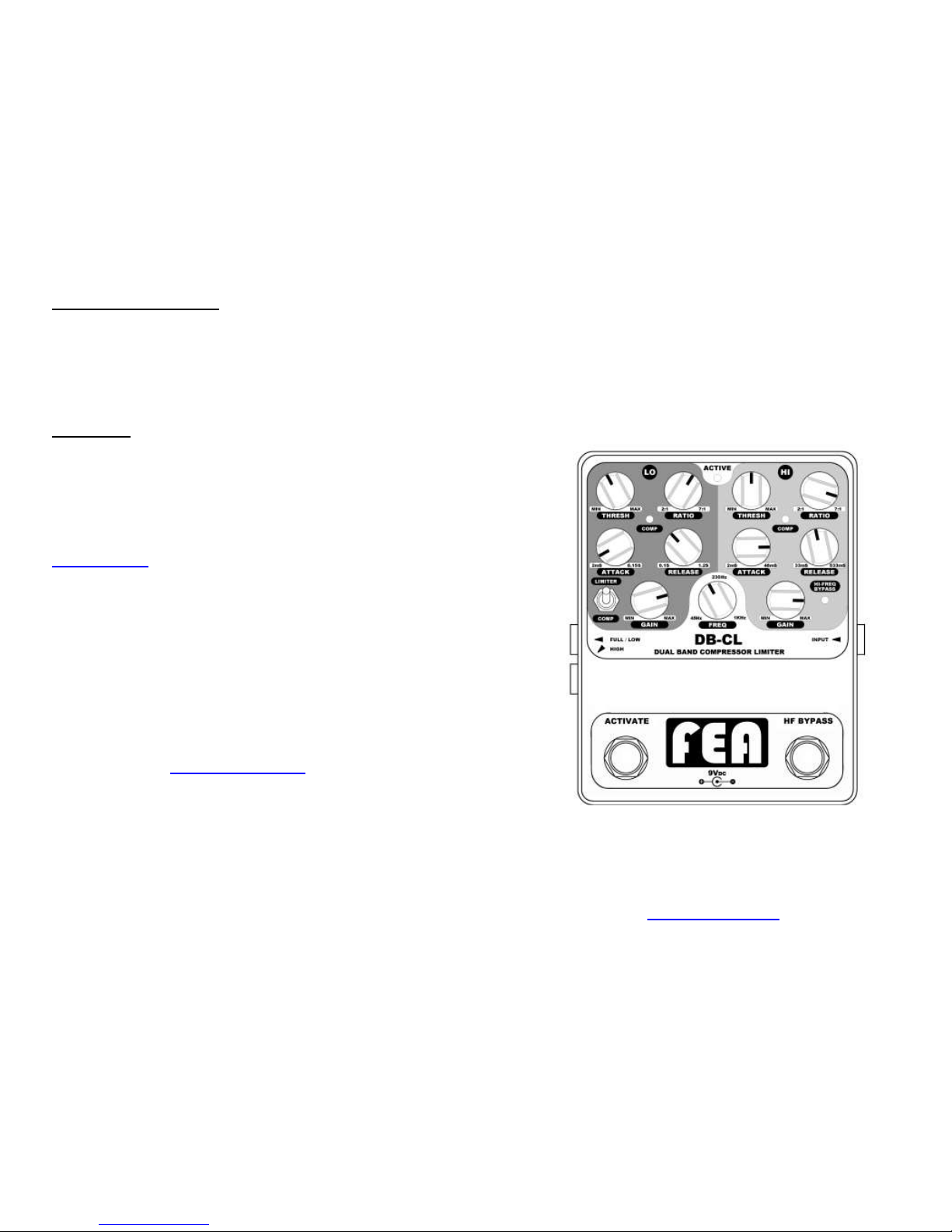
DUAL BAND
COMPRESSOR LIMITER
www.fealabs.com
Battery replacement:
Remove the four screws on the bottom cover to access the battery
compartment. If storing the unit for long periods of time the battery
should be removed to prevent corrosion of the battery snap. Be sure
to place the battery wires along the side of the battery in the battery
pocket and use care while replacing the bottom cover.
Warranty:
The FEA Dual Band Compressor Limiter is fully covered for a period
of 5 (five) years and the foot switches are covered for 1 (one) year
against defects in material and workmanship. Abuse and neglect are
not covered under the warranty. Any modifications or repairs not
authorized by FEA voids all warranties. The customer will be
responsible for shipping cost to and from FEA Labs for repairs.
Contact me before attempting to ship a unit for repair at:
info@fealabs.com.
All repairs made outside of the warranty period will be very
reasonable (usually only the cost of the parts)… your satisfaction is
priority one.
Contact FEA Labs at:
www.fealabs.com
info@fealabs.com
REV 4.1
Page 2

Technical Specifications:
Crossover FREQ: 45Hz to 1KHz @ 12dB/Oct
ATTACK: HI 2mS to 48mS
LO 2mS to 150mS
RELEASE: HI 33mS to 533mS
LO 100mS to 1200mS
RATIO: 2:1 to 7:1 LIMITER: :1
THRESHOLD: -44dBu to
Make-up GAIN: 0 to 20dB
Maximum Input: 7.8dBu
Maximum Output: 13dBu
Residual Output Noise: -66dBu from 10Hz-20kHz
(un-weighted) with no
compression and output gains set
to maximum. **This is the absolute
worst case noise scenario.**
Frequency Response: 10Hz – 21KHz +1.25/-3dB
Input Impedance: 1M ohm
Output Impedance: 1K ohm
Power adapter 40dBu @ 60Hz
noise rejection: >90dBu @ 2KHz
Current Consumption: Approx. 36mA
Battery Life: Approx. 11 hours continuous use
Power adapter (optional): 9VDC 2.1mm negative center pin
About the design:
Optical compressors are still preferred over VCA (voltage
controlled amplifier) compressors in most recording studios for
some instruments. One of those instruments where optical is
favored is on the bass guitar for its smooth attack and release
characteristics.
Optical compressors use a photocell (photo-resistive cell) and a
light source projected onto the photocell to vary the value of
resistance inversely proportional to the light intensity. Years
ago these were made with a discrete photocell and light
source. There are now devices that contain both the photocell
and light source in a single package. They are referred to as
Vactrols and AOI’s (analog optical isolators). The drawbacks of
these devices in the past have been with their reaction and
recovery times. If the photocell were formulated for a quick
reaction to light, the resistance would take a long time to settle
back after the light has been removed. The opposite is also
true; if the photocell were formulated for a quick recovery after
the light has been removed then the reaction to light would be
slow. The Luna Optoelectronics™ Company (formerly
Silonex™) uses a combination formula for the photocell to
overcome these limitations in the AOI that is used in the FEA
Dual Band Compressor Limiter or DB-CL. This very same AOI
is used in some high-end studio compressors for its smooth
attack and release qualities. This fast AOI allows the sidechains in the compressor-limiter to accurately control the Attack
and Release times of the compression. The purely resistive
element in the AOI exhibits less noise and distortion than most
designs using a VCA. Most audiophiles advocate that only
good quality passive components should be in the audio signal
path and this is one application that I would have to agree with
them.
Along with these fantastic AOI’s, the FEA DB-CL utilizes 1%
metal film resistors, multi-layer metalized polyester film
capacitors and hi-fi quality Texas Instrument™ JFET
operational amplifiers in the signal paths. The input stage is a
high impedance CMOS, hi-fi operational amplifier buffer with
internal RFI protection. The input amplifier has been designed
to have minimal signal distortion and noise, with maximum
Page 1
Page 6
Page 3

headroom for all input signal levels.
The dual rail power supply in the DB-CL is built on its own
discrete circuit board to physically separate it from the audio
circuits. The power supply is over filtered two times to assure
exceptionally clean power for the signal circuitry. This power
supply provides 18Volts (+9V and -9V) to the compressor
circuit board to provide plenty of headroom for the signal. The
power supply was designed to provide separate power for all of
the side-chain control circuitry. This assures that any natural
electrical noise that the compressor side-chain control circuitry
generates will not bleed into the signal circuitry. I have not seen
this approach to power distribution in any of the other
manufacturer’s guitar effects. Is it overkill? Maybe…but I feel
that it is absolutely crucial to eliminate every bit of noise where
possible.
Frank E. Appleton (FEA)
Min-Max and Limit RATIOS:
Threshold set at –25dB for all tests.
Page 5
Page 2
Page 4

components (Light Dependent Resistors or Photocell). All
resistors in the circuit are low noise 1% metal film type. The
signal coupling capacitors are tight tolerance, quiet, multilayer and metalized polyester film type. The amplifiers used
in the signal path are JFET input, low-noise, low-distortion
“hi-fi quality” devices.
The power supplies onboard voltage charge pump allows
the circuitry to operate at 18volts (+9 and –9 volt rails) from
a single 9 volt battery or 9 volt DC power adapter. This
allows the signal plenty of headroom from active electronic
guitars and aggressive playing techniques (i.e. pop and
slap).
The “switch on” power supply current is less than 1µA
(micro amp) on the signal ground at the INPUT jack. This is
approximately 45,000 times (-93dB) less than the commonly
used method of connecting the battery’s negative terminal
to ground via the sleeve of the plug inserted into the INPUT
jack. The “switch on” sensing method used in the FEA
Dual-Band Compressor-Limiter keeps nearly all of the
circuit’s generated white noise and transient currents out of
the INPUT stage signal ground. Extreme measures have
been taken to keep the power and signal paths as clean as
possible. NOTE: Unplug the cord from the INPUT jack when
not in use to prolong battery life.
The power and grounds for the signal path circuitry are
separated from the side-chain power and grounds to
protect the audio signal from spurious noise. The power for
the signal amplifiers is exceptionally clean, filtered twice for
each rail and all filter stages are oversized.
HI and LO/FULL output jacks are configured so the outputs
of the individual compressors may be routed to different
amplifiers or effects. The HI output is useful if you wish to
use effects made strictly for guitar and route a clean LO
signal to another amplifier or mixer. If only the LO/FULL
output jack is used, both the HI and LO signals are mixed
together for a composite full range output signal.
Features:
Dual optical compressors for separate Low frequency (LO)
and High frequency (HI) dynamics control.
Adjustable frequency crossover point with the range tailored
for bass guitar.
The frequencies above 5KHz are routed around the
compressor circuits and are mixed back into the output
amplifiers at unity gain to preserve clarity.
THRESHOLD, RATIO, ATTACK, RELEASE and GAIN controls
for the HI and LO compressors. The control ranges for the
ATTACK and RELEASE have been independently optimized
for the LO and HI bands.
Both bands exhibit soft-knee compression at lower RATIO
settings and hard-knee at maximum RATIO settings. The
COMP LED indicates when the THRESHOLD has been
reached. This LED does not indicate the RELEASE
response.
The LIMITER switch changes the LO band compressor into a
LO band limiter. The LO RATIO control is bypassed and hard
limiting is applied and set by the THRESHOLD level control.
The compressor-limiter side-chains use precision full-wave
rectification of the audio signals in the THRESHOLD circuits
to improve tracking. This also reduces the possibility of
“pumping” with very low frequencies.
HI BYPASS foot switch. This allows the compressor-limiter to
only control the Low frequencies (if desired) and to pass the
High band frequencies to the outputs unaffected. There is a
red LED to indicate the HF BYPASS is on. NOTE: With HI
BYPASS active the HI GAIN control is inactive.
ACTIVATE foot switch places the compressor-limiter unit in
the signal chain or in Direct Bypass mode. In Direct Bypass
mode the signal at the input is directly connected to the
outputs.
The compressors have minimal components in the signal
paths to maintain the utmost signal quality. The signal
compression-limiting is accomplished with only resistive
Page 3
Page 4
 Loading...