

FDK MULTI7 Instruction Manual
Page 1 of
10
DM??C
MULTI 7 ANATEXJR
1-
1
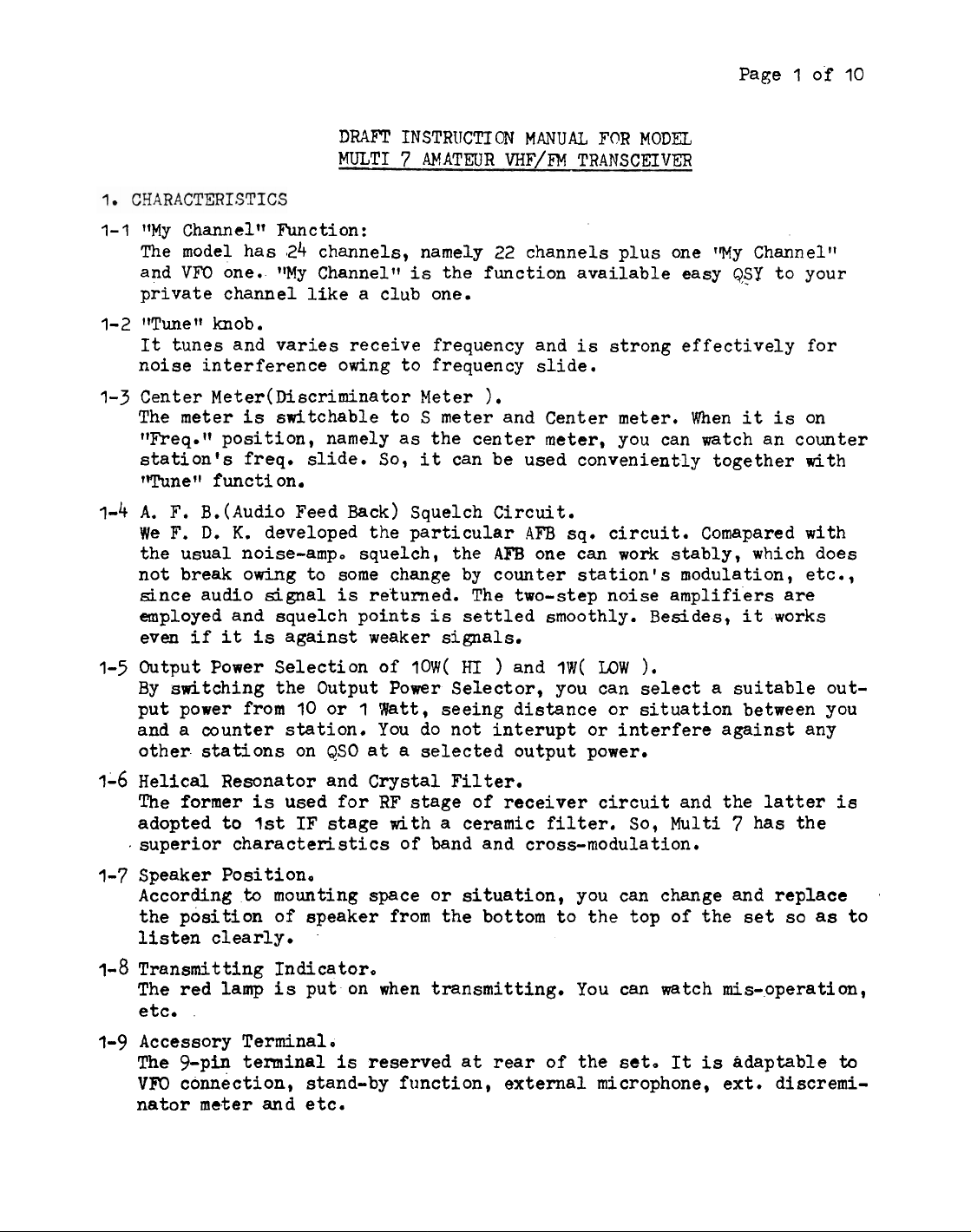
1fMy Channeltf Function
The model has 24 channels, namely 22 channels plus one fWy Channeltl
and
VFO
one.. "My Channel"
private channel like a club one.
1-2 ttTunet' knob.
It
tunes and varies receive frequency and
noise interference owing to frequency slide.
1-3 Center Meter(M6criminator Meter
The meter
Vreq.It position,
station's freq.
1TunefI function.
1-4
A.
F.
We
F.
the usual noise-amp. squelch, the
not break owing to some change by counter station's modulation, etc.,
since audio signal
employed and squelch points
even if
is
switchable to S meter and Center meter. When
namely as the center meter, you can watch an counter
slide. So,
B.
(Audio Feed Back) Squelch Circuit.
D.
K.
developed the particular
is
it
is
against weaker signals.
INSTRIJCTION
:
is
the function available easy
MANUAL
VHF/FM
FOR
MODEL
TRANSC'EIVFR
is
strong effectively
&SY
1.
it
it
can be used conveniently together with
4FB
sq. circuit. Comapared with
AFB
one can work stably, which does
returned. The two-step noise amplifiers are
is
settled smoothly. Besides,
it
to your
for
is
on
works
1-5
Output Power Selection of
By switching the Output Power Selector, you can select a suitable output power from
and
a
counter station. You do not interupt or interfere against any
other stations on
1-6
Helical Resonator and Crystal Filter.
The former
adopted to
.
superior characteristics of band and cross-modula tion.
1-7
Speaker Position,
According
the position of speaker from the bottom to the top of the set so
listen clearly.
1-8
Transmitting Indicator,
The red
etc.
1-9
Accessory Terminal.
The +pin terminal
VFO
connection, stand-by function, external microphone, ext. discremi-
nator meter and etc.
to
lamp
I0
or 1 Wtt, seeing distance or situation between you
QSO
is
used for RF stage of receiver circuit and the latter
1st
IF stage with a ceramic filter. So, Multi 7 has the
mounting space or situation, you can change and replace
is
put on when transmitting. You can watch mis-operation,
is
?OW(
HI
)
and
I\(
LOW
at a selected output power.
reserved
at
rear of the
set.
).
It
is
adaptable
as
is
.
to
to
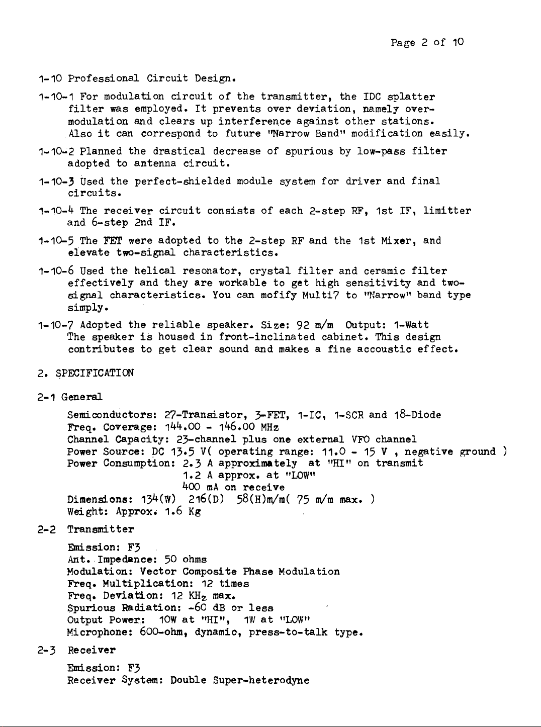
1- 10 Professional Circuit Design.
Page 2 of
10
1-70-1 For modulation circuit of the transmitter, the
was
filter
modulation and clears up interference against other stations.
Also
it
1-10-2 Planned the drastical decrease of spurious by low-pass filter
adopted to antenna circuit.
7-10-3 used the perfect-shielded module system for driver and final
circuits.
1-10-4 The receiver circuit consists of each 2-step
and 6-step 2nd IF.
1-10-5 The
eievate two-signal characteristics.
1-10-6 Used the helical resonator, crystal filter and ceramic filter
effectively and they are workable to get high sensitivity and twosignal characteristics. You can mofify Multi7 to 1lWarrowll band type
simply.
1-10-7 Adopted the reliable speaker. Size: 92
The speaker
contributes to get clear sound and makes
2.
SPECIFICATION
FET
employed.
can correspond to future tWarrow Band" modification easily.
were adopted to the 2-step RF and the 1st Mixer, and
is
housed in front-inclinated cabinet. This design
It
prevents over deviation, namely over-
m/m
a
fine accoustic effect.
IDC
splatter
W,
1st IF, lirnitter
Output: I-Watt
2-1 General
semiconductors: 27-Transistor,
Freq. Coverage: 144.00
Channel
Power
Power ~onsumpt'ion:
Dimensions: 134(~) 216(~)
Weight: Approx.
2-2
Transmitter
Wssion:
Ant.
Modulation: Vector Composite Phase Modulation
Freq. Multiplication: 12 times
Freq. Deviation: 12
Spurious
Output Power:
Mi
crophone : 600-ohm, dynamic, press- to-
2-3 Receiver
Emission:
Receiver System: Double Super-heterodyne
Capacity:
Sou.rce:
DC
13.5
1.6
F3
Impebnce: 50 ohms
Radiation:
10W
F3
-
146.00
2Fchannel plus one external
V(
operating range: 11.0 - 15
2.3
A
approximately
1.2 A approx. at
400
mA
on receive
Kg
KHz
max.
-60
d~
at
llHI",
SFET,
MHz
58(~)m/rn(
or less
1VI
at 'lLON"
1-IC, 1-SCR and 18-~iode
VFO
channel
V
,
negative ground
at
flHI"
on transmit
"LOW"
75
dm
tall
max.
type.
)
)
Speaker: 92
2-4
Accessories
6.
7.
Page 3 of 10
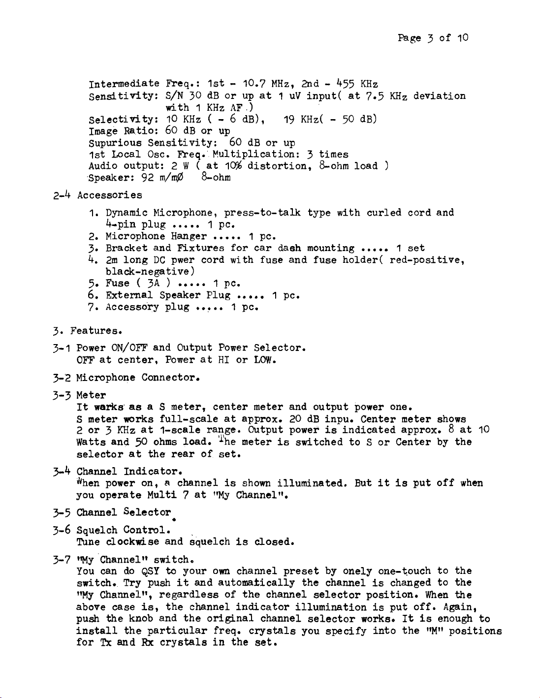
Intermediate Freq.: 1st - 10.7 MHz, 2nd - 455 KHz
sensitivity: S/N
selectivity:
Image Ratio: 60 dB or up
supurious Sensitivity: 60 d~ or up
1st
Local Osc. Freq.'. P!ultiplication:
Audio output:
m/n$
1.
Dynamic Microphone, press-to- talk type with curled cord and
4-pin plug
2. Microphone Hanger
3.
Bracket and Fixtures for car dash mounting
4.
2m long
black-negative
5.
Fuse
External Speaker Plug
Accesso'ry plug
DC
(
3A
30
dB or up at 1 uV input( at 7.5
1
KHz
AF
-
I&
pc.
.)
6
dB),
distortion,
1
pc.
19
KHz(
-
3
times
&ohm load
50 d~)
with
10
KHz
2
W
.
.
.
(
&ohm
. .
(
at
1
.....
. . . . .
pwer cord with fuse and fuse holder(
)
)
.....
1 pc.
.
.. . .
. . . .
1
pc.
.
I
pc.
KHz
deviation
)
1
set
red-positive,
3.
Features.
3-1 Power
OFF
3-2 Microphone Connector.
3-3
Meter
It
S
2
Watts and
selector
3-4
Channel Indicator.
gdhen power on, A channel
you operate Multi
35
Channel Selector
3-6
Squelch Control.
Tune
3-7
Vy 'channel" switchYou can do QSY
switch.. Try push
'my
above case
push the knob and the original channel selector workso
install the particular
for
ON/OFF
at
center, Power at
warks
meter
or 3 KHz
arorks
clockarise
Channel", regardless of the channel selector position. When the
hc
and
and Output Power Selector.
HI
or
as
a S meter,
full-scale
at
1-scale range. Output power
50
ohms load. 'he meter
at
the rear of set.
7
and squelch
to
your own channel preset by onely one-touch to the
it
is,
the channel indicator illumination
Rx
crystals
center meter and output power one.
at
approx. 20 dB inpu.
is
shown illuminated. But
at
"My Channel".
is
and automafrically the channel
freq. crystals you specify into the
in
the set.
LOW.
is
closed.
is
indicated approx.
switched to S or Center by the
Center meter shows
8
at
it
is
put off when
is
changed to the
is
put off. Again,
It
is
enough to
"Mu
positions
10
Page 4 of 10
3-8
Tune Knob.
~t
mrks to revise freq. slide. Set the knob
can listen most clearly.
frequency comes to higher. Other hand, the receive frequency comes to
lower when the knob ia tuned counter-clockwise.
3-9
Volume Control.
When you tune the knob clockwise, volume comes up.
3-10 ~ransrnittin~ Indicator Lamp.
It
puts on when transmitting, namely, you press the "Push-to-talkH
button on the microphone.
3-11
Meter Function Switch.
Set the switch at "S" position, the meter works
hand,
when you set
it
If
the knob
at
"Freq." position,
is
at
a position that you
tuned clockwise, receive
as a S meter. Other
it
works
as
a Center meter.
3-72
3-13
3-14 Power Cord Connector. Use the accessory one.
3-15
4.
4-1
4-2
Ekt.
Speaker Jack.
When you use
plug furnished.
Antenna Co~ector. Use a M
required.
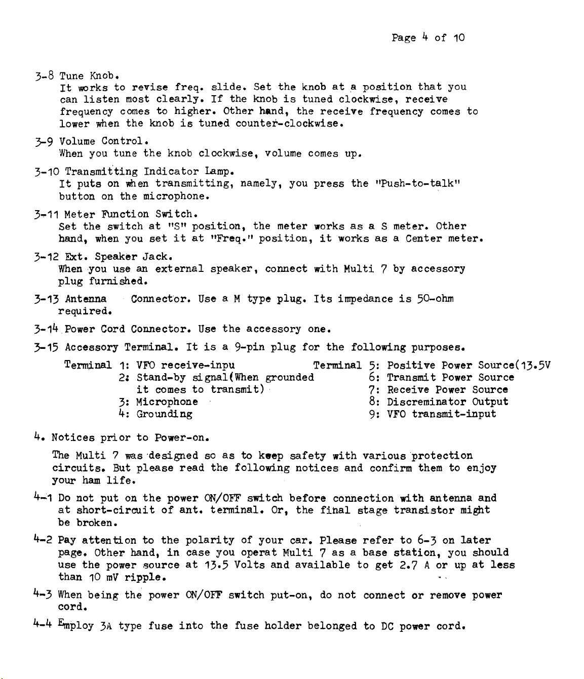
Accessory Terminal.
Temj.nal
Notices prior to Power-on.
The Multi 7 was.designed so as
circuits. But please read the following notices and confirm them to enjoy
your ham life.
Do not put on the power
at short-circuit of ant. terminal.
be broken.
Pay attention to the polarity of your car. Please refer to
page. Other hand, in case you operat Multi
use the power source
than 10
mV
an
external speaker, connect with Multi 7 by accessory
type plug.
It
is
a
9-pin plug for the following purposes.
I:
VFO
receive-inpu Terminal
2:
Stand-by signal (When grounded
it
comes to transmit)
3:
Microphone
4: Grounding
to
keep safety with various protection
ripple.
at
ON/OFF
13.5
switch before connection
Or,
Volts and available to
Its
impedance
6:
7:
the fibal stage transistor
7
as
a
base station, you should
is
50-ohm
5:
Positive Power Source(
Transmit Power Source
Receive Power Source
8:
Discreminator Output
9:
VFO
transmit-input
with
antenna and
6-3
on later
get
2.7 A or up at
-
,
13.5V
mi&t
less
4-3 When being the power ON/OF'F switch put-on, do not connect or remove power
cord.
4-4 hploy
3A
type fuse into the fuse holder belonged to
DC
power cord.
 Loading...