

Page 1
USB-ICP-SAB9
FDI
Quick Start Guide
FDI
USB-ICP-SAB9 Quick Start Guide
The USB-ICP-SAB9 is a Socket Adapter Board designed to be used with the USB In-Circuit Programmer for
NXP Semiconductors LPC9xx devices. The SAB9 allows the user to program and test these microcontrollers
outside of the application circuit. Throughout this document we will just refer to the SAB9 rather than using the
complete part number since it simplifies the flow of information.
THE USB-ICP-SAB9 WILL NOT WORK WITHOUT A USB-ICP PROGRAMMER!
MAKE SURE TO INSTALL THE USB-ICP BEFORE USING THE SAB9!
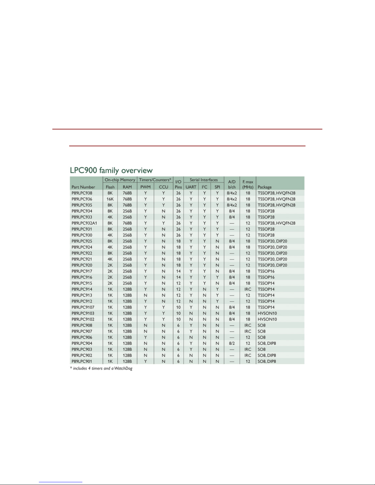
Notice above that not all parts come in all packages. For instance, in the LPC93x family none of the devices
come in a DIP package. Therefore, for simplicity this document is arranged by package type rather than by part
family.
Page 1 of 15 Rev 1.0
Page 2
USB-ICP-SAB9
FDI
Quick Start Guide
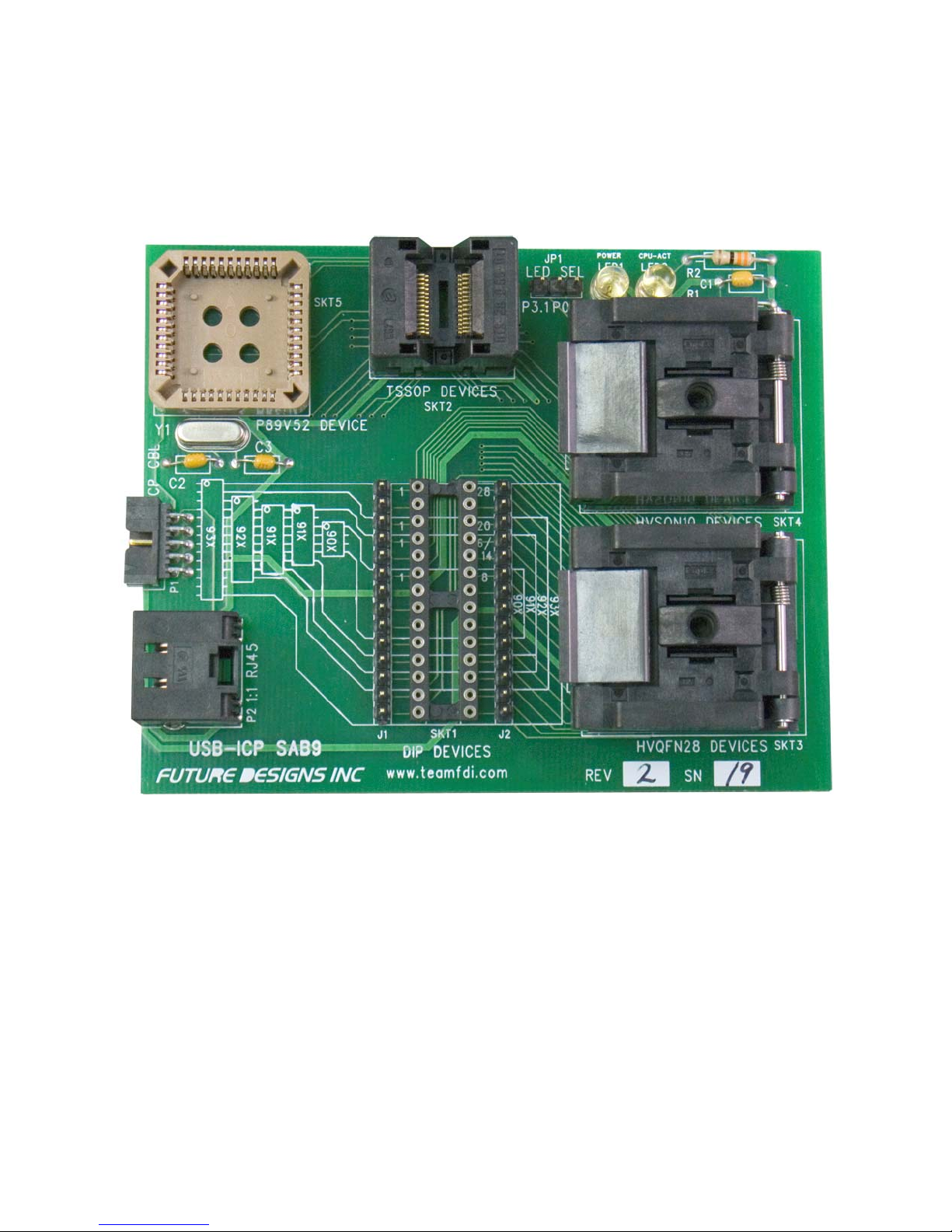
USB-ICP-SAB9 socket layout:
FDI
Each socket on the board is clearly labeled for the type of part that is programmed in it. When this document
refers to the ‘top’ of the board, this is referring to the top of the board when it is in the orientation shown in the
picture above.
Page 2 of 15 Rev 1.0
Page 3
USB-ICP-SAB9
FDI
Quick Start Guide
FDI
Connecting the USB-ICP-SAB9 to a USB-ICP
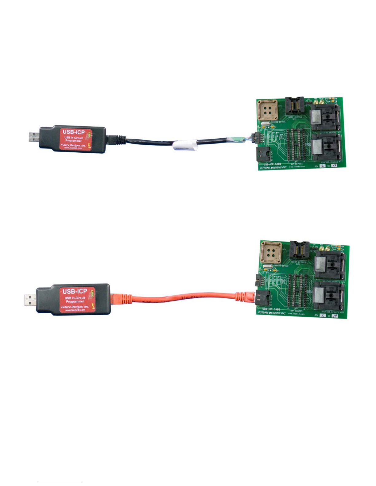
To use the SAB9, it must first be connected to a PC through a USB-ICP with a USB-ICP-LPC9xx cable to P1,
as shown above. Or, if you do not have the USB-ICP-LPC9xx, the SAB9 may be connected to the PC with
regular Ethernet Patch cable to P2, as shown below. The USB-ICP must then be connected to the USB port on
your PC. To learn more about using the USB-ICP, please visit www.teamfdi.com/usb-icp
Page 3 of 15 Rev 1.0
Page 4

USB-ICP-SAB9
FDI
Quick Start Guide
FDI
Frequently Asked Questions
For frequently asked questions regarding the USB-ICP please visit: www.teamfdi.com/usb-icp
Error Messages when Using Flash Magic
Flash Magic is the PC GUI interface software used with the USB-ICP programmer. If you are receiving error
messages when you try to program parts, go to ISP -> Read Device Signature and check below.
1. If the device signature reads all FF’s verify the following:
a. The part is oriented in the socket correctly.
b. The USB-ICP is connected to the SAB9 board according to one of the two methods mentioned
on Page 3.
c. That you do have a part in the socket.
d. That there is only one part in the board (you cannot program in two different sockets at the same
time)
2. If Flash Magic tells you that it failed to autobaud:
a. Make sure that the correct device is selected in the device drop-down menu.
3. If you receive the error message ‘Unable to communicate. (in use) Ensure no other applications
are using the COM Port. Try raising or lowering the baud rate.”
a. Make sure that you have the correct port selected and that the baud rate you have selected is the
rate recommended for the USB-ICP
Page 4 of 15 Rev 1.0
Page 5
USB-ICP-SAB9
FDI
Quick Start Guide
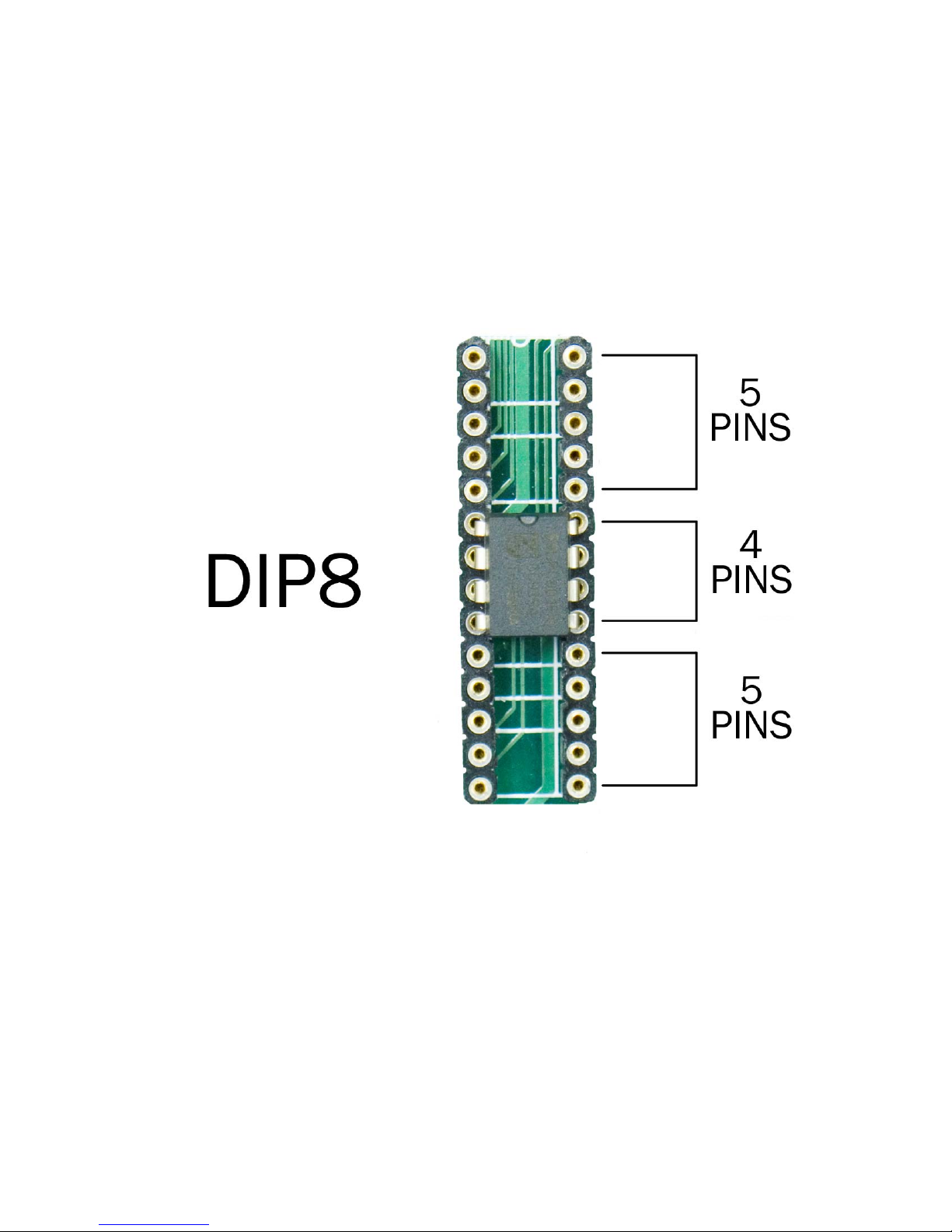
P89LPC90x Devices in DIP8 Package:
SKT1
FDI
When placing any DIP8 Part in the SAB9 for programming, there must be 5 pins empty above and below the
part being programmed. The pin one identifier (notch in chip) should be toward the top of the board.
Page 5 of 15 Rev 1.0
Page 6
USB-ICP-SAB9
FDI
Quick Start Guide
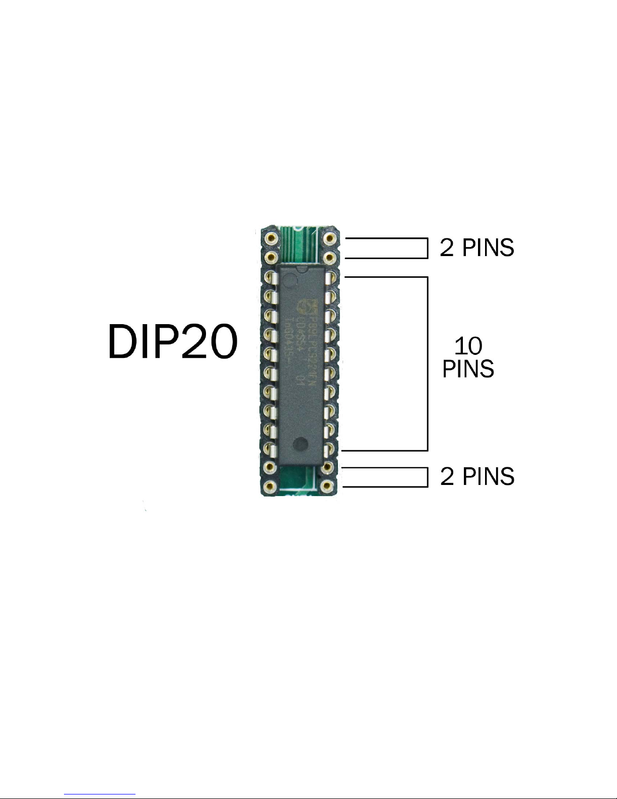
P89LPC2x Devices in DIP20 Package:
SKT1
FDI
When placing any DIP20 Part in the SAB9 for programming, there must be 2 pins empty above and below the
part being programmed. The pin one identifier (notch in chip) should be toward the top of the board.
Page 6 of 15 Rev 1.0
Page 7
USB-ICP-SAB9
FDI
Quick Start Guide
FDI
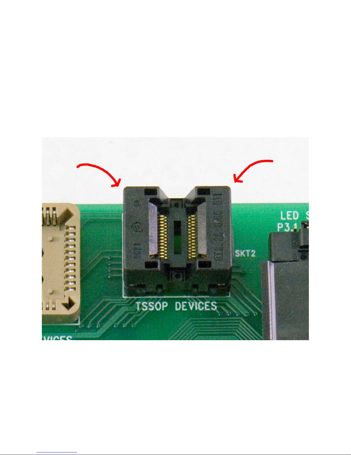
Using the TSSOP Socket (SKT2)
To place a part in the TSSOP socket for programming, first push down on both sides of the socket with two
fingers. Then, once the socket is ‘open’ drop the part into the socket and nudge it into place to match the
documents below. When you release the sides of the socket the part will be locked in and ready for
programming.
Page 7 of 15 Rev 1.0
Page 8
USB-ICP-SAB9
FDI
Quick Start Guide
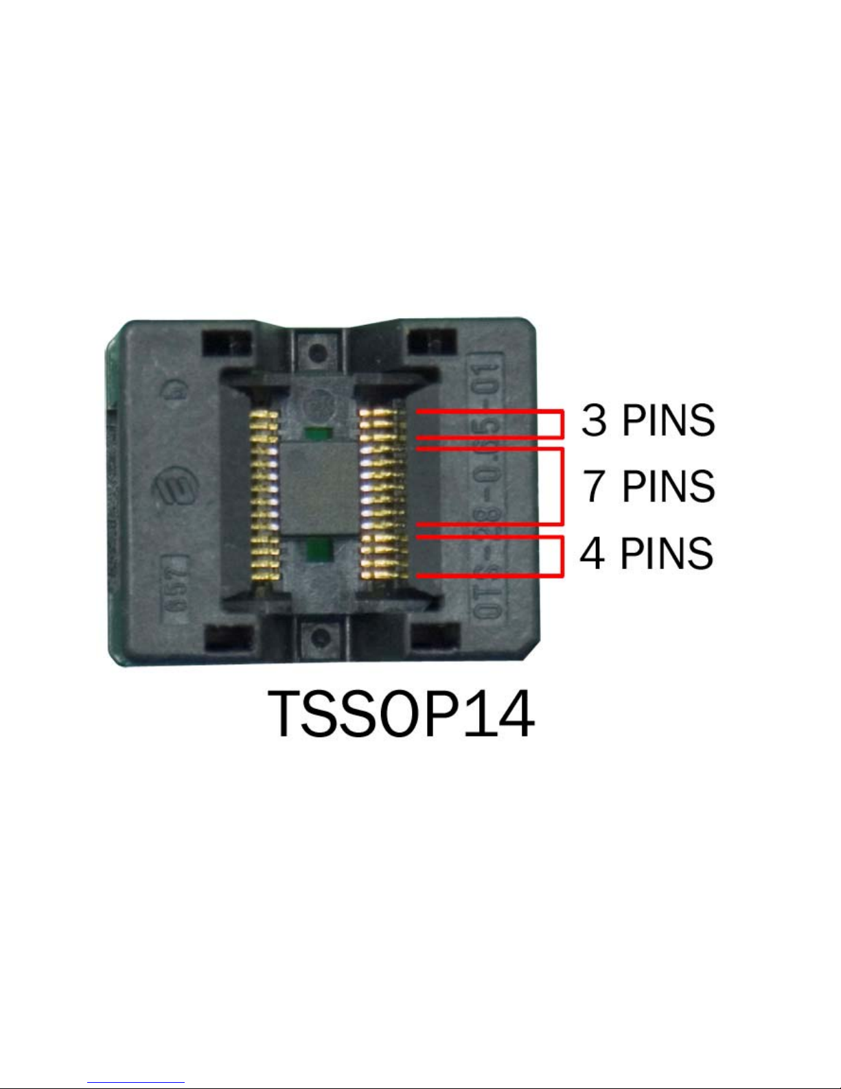
P89LPC91x Devices in TSSOP14 Package:
SKT2
FDI
When placing any TSSOP14 Part in the SAB9 for programming, there must be 3 empty pins above and 4 empty
pins below the part being programmed. The pin one identifier (circle in top left corner) should be toward the
top of the board.
Page 8 of 15 Rev 1.0
Page 9
USB-ICP-SAB9
FDI
Quick Start Guide
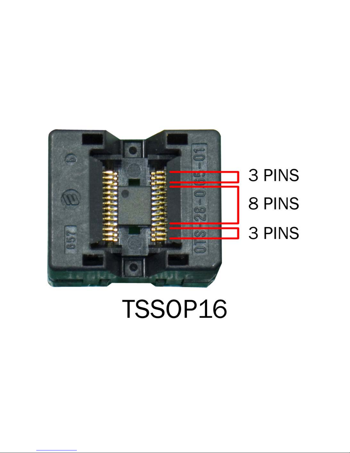
P89LPC91x Devices in TSSOP16 Package:
SKT2
FDI
When placing any TSSOP16 Part in the SAB9 for programming, there must be 3 empty pins above and below
the part being programmed. The pin one identifier (circle in top left corner) should be toward the top of the
board.
Page 9 of 15 Rev 1.0
Page 10
USB-ICP-SAB9
FDI
Quick Start Guide
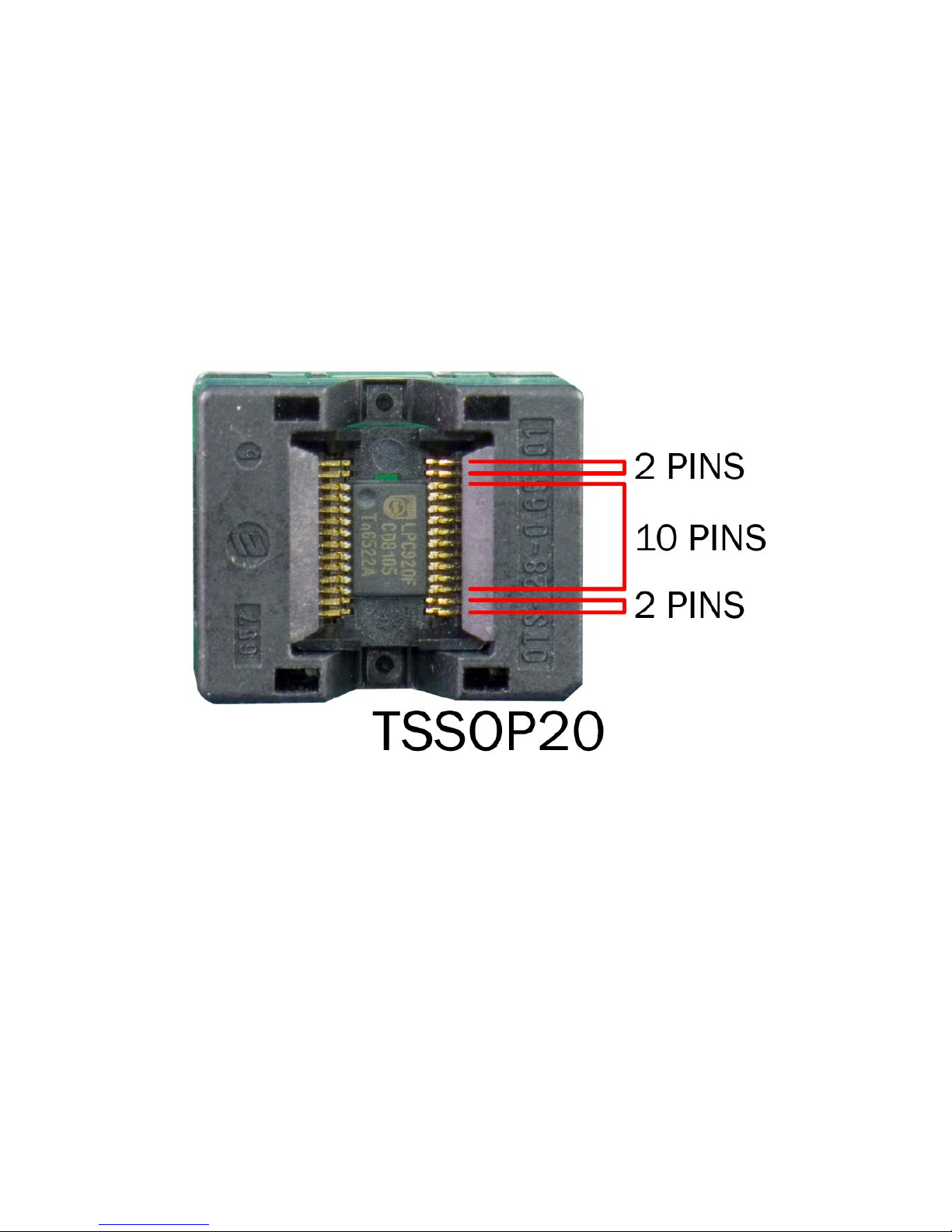
P89LPC92x Devices in TSSOP20 Package:
SKT2
FDI
When placing any TSSOP20 Part in the SAB9 for programming, there must be 2 pins empty above and below
the part being programmed. The pin one identifier (circle in top left corner) should be toward the top of the
board.
Page 10 of 15 Rev 1.0
Page 11
USB-ICP-SAB9
FDI
Quick Start Guide
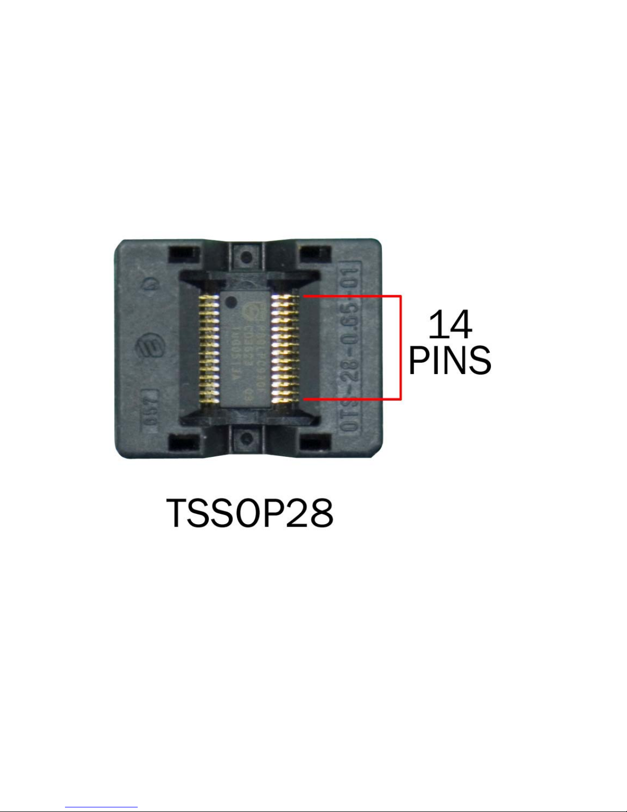
P89LPC93x Devices in TSSOP28 Package:
SKT2
FDI
When placing any TSSOP28 Part in the SAB9 for programming, the part should take up the entire socket and
there should be no empty pins. The pin one identifier (circle in top left corner) should be toward the top of the
board.
Page 11 of 15 Rev 1.0
Page 12
USB-ICP-SAB9
FDI
Quick Start Guide
FDI
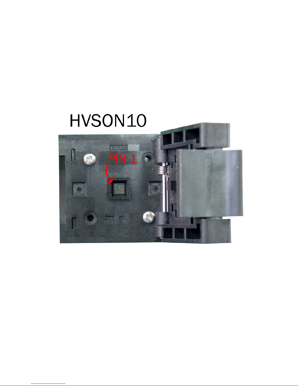
P89LPC910x Devices in HVSON10 Package:
SKT4
When placing any HVSON10 Part in the SAB9 for programming, the part should be turned so that the pin 1
identifier is in the upper left corner of the socket.
Page 12 of 15 Rev 1.0
Page 13
USB-ICP-SAB9
FDI
Quick Start Guide
FDI
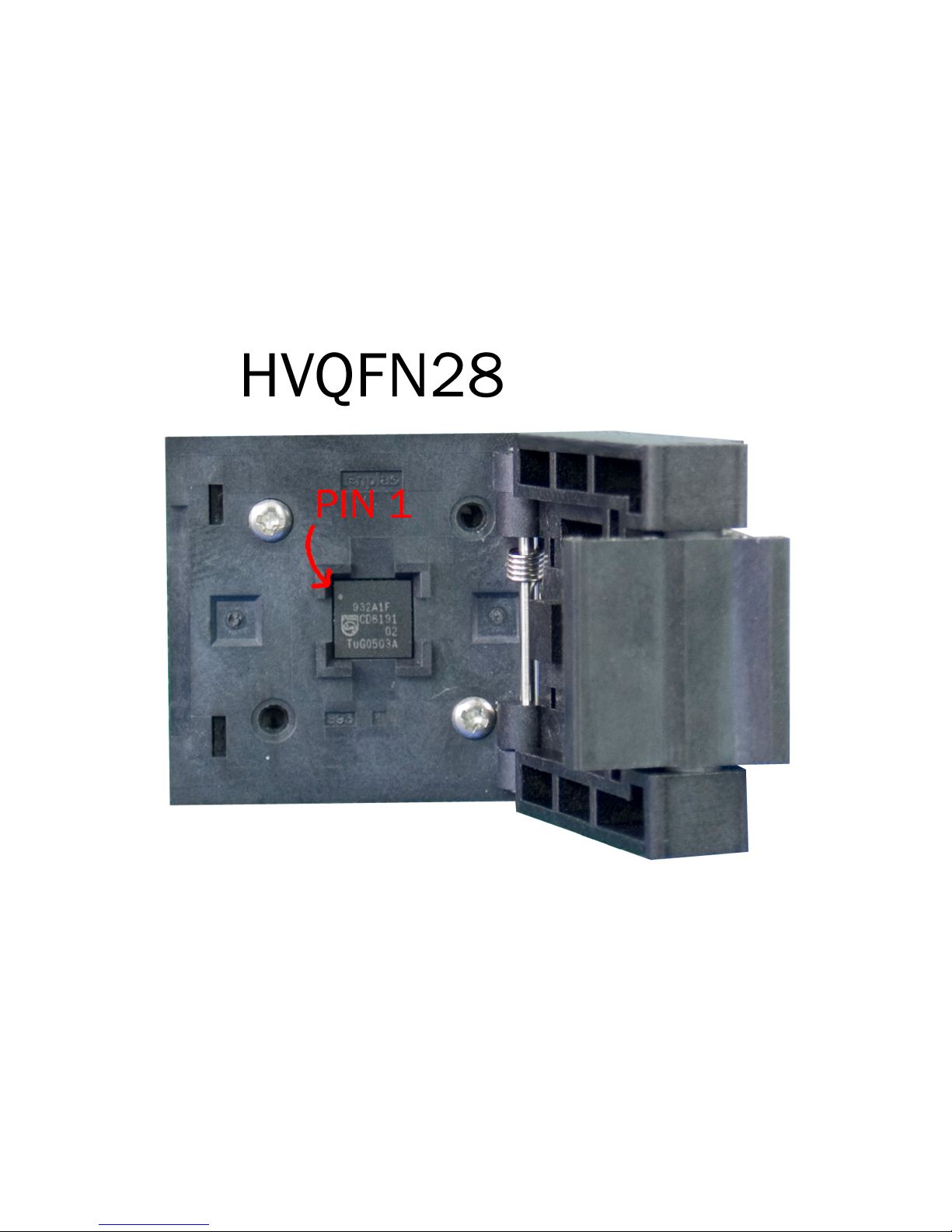
P89LPC93x Devices in HVQFN28 Package:
SKT3
When placing any HVQFN28 Part in the SAB9 for programming, the part should be turned so that the pin 1
identifier is in the upper left corner of the socket.
Page 13 of 15 Rev 1.0
Page 14

USB-ICP-SAB9
FDI
Quick Start Guide
FDI
LED and Jumper function
LED1: This LED is the power indicator and should be illuminated when the SAB9 board is plugged into an
active USB-ICP.
LED2: This LED can be used as the standard ‘heartbeat’ monitor. By adding code to blink this LED you can
verify that your microcontroller has been correctly programmed through the SAB9. This LED can be connected
to one of two different I/O pins by using the JP1 jumper as shown. LED2 is routed to these I/O pins on each of
the socket options available on the SAB9 so this function can be used on any package type.
JP1 1-2: LED 2 connected to P0.6
JP1 2-3: LED 2 connected to P3.1
If you have any further questions, please contact FDI at [email protected]
Page 14 of 15 Rev 1.0
Page 15
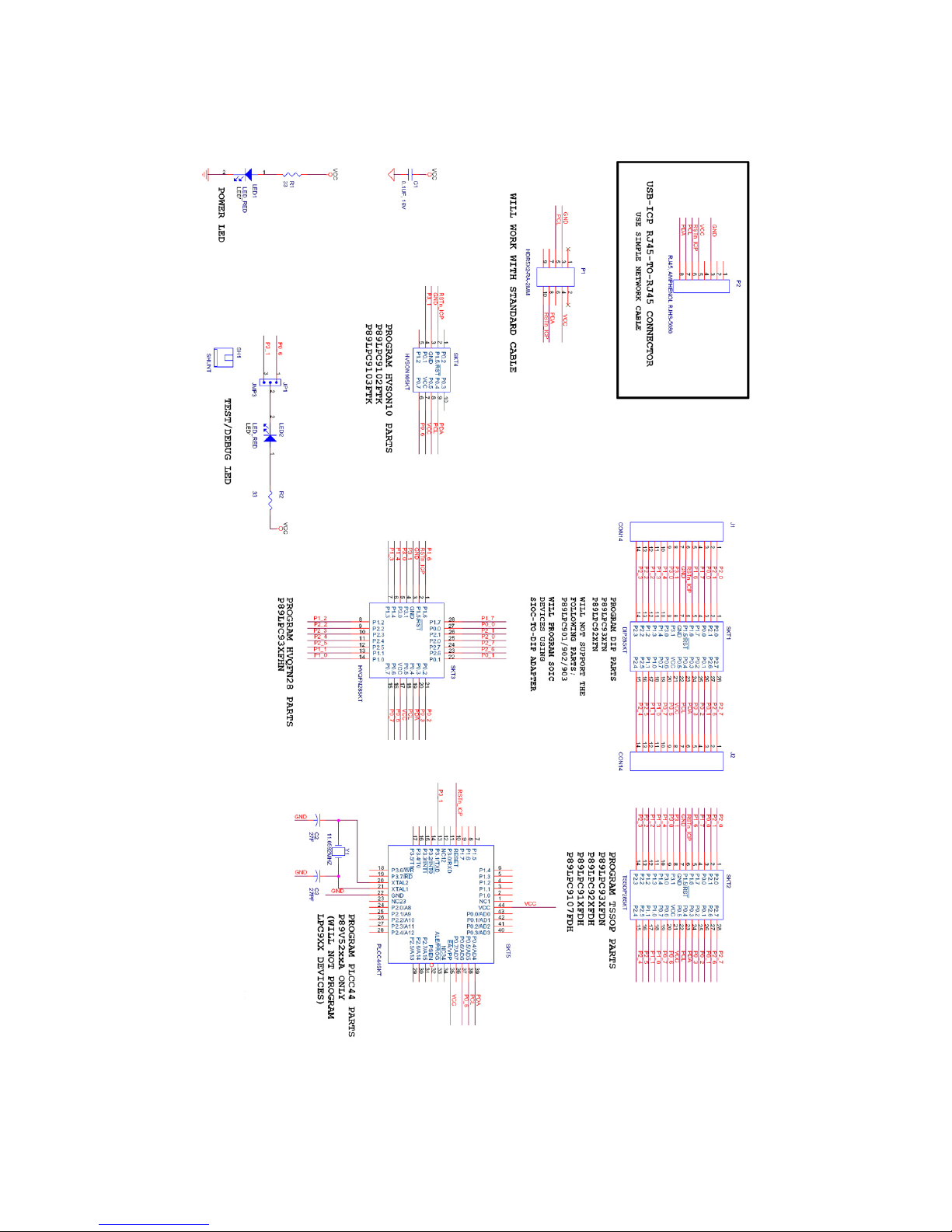
USB-ICP-SAB9
FDI
Quick Start Guide
FDI
Page 15 of 15 Rev 1.0
 Loading...