

FDI uEZGUI-EXP-DK User Manual
uEZGUI-EXP-DK
User’s Manual
Copyright ©2013, Future Designs, Inc., All Rights Reserved

Table of Contents
1. Introduction ______________________________________________________________________________ 1
2. Kit Contents ______________________________________________________________________________ 1
3. Functional Description _____________________________________________________________________ 1
4. Requirements _____________________________________________________________________________ 1
5. ESD Warning______________________________________________________________________________ 2
6. Startup Procedure _________________________________________________________________________ 2
7. Mechanical Details ________________________________________________________________________ 2
8. Expansion Board Top Level Mechanical Diagram / Board Layout ___________________________________ 3
9. Expansion Board Functional Block Diagram ____________________________________________________ 4
10. JP23 Setting for LPC based uEZGUIs or RX based uEZGUIs. ________________________________________ 5
11. Expansion Connector pin usage ______________________________________________________________ 5
12. Expansion Connector Cable Details ___________________________________________________________ 7
13. DC Power Input – P8 _______________________________________________________________________ 7
14. USB Host – P3 _____________________________________________________________________________ 7
15. USB Device – P4 ___________________________________________________________________________ 8
16. Ethernet – J3 _____________________________________________________________________________ 8
17. Power over Ethernet – SIP1 (optional) _________________________________________________________ 9
18. PMOD – J9 _______________________________________________________________________________ 9
19. Potentiometer – VRES _____________________________________________________________________ 10
20. FET Driver – J10 __________________________________________________________________________ 10
21. DALI – J12 (not loaded by default) ___________________________________________________________ 10
22. RS232 – P5 ______________________________________________________________________________ 11
23. MicroSD – J8 _____________________________________________________________________________ 11
24. RS485 – P6 ______________________________________________________________________________ 12
25. CAN – J13 _______________________________________________________________________________ 12
26. I2C System – JP13 ________________________________________________________________________ 13
27. Audio System – JP 16 and JP17 ______________________________________________________________ 14
28. Additional Documentation, Schematics, and Software Updates ___________________________________ 14
Information in this document is provided solely to enable the use of Future Designs products. FDI assumes no liability whatsoever, including
infringement of any patent or copyright. FDI reserves the right to make changes to these specifications at any time, without notice. No part of
this document may be reproduced or transmitted in any form or by any means, electronic or mechanical, for any purpose, without the express
written permission of Future Designs, Inc. 996 A Cleaner Way, Huntsville, AL 35805.
For more information on FDI or our products please visit www.teamfdi.com.
NOTE: The inclusion of vendor software products in this kit does not imply an endorsement of the product by Future Designs, Inc.
2013 Future Designs, Inc. All rights reserved.
uEZ® is a registered trademark of Future Designs, Inc.
Other brand names are trademarks or registered trademarks of their respective owners.
FDI PN: MA00030
Revision: 1.0, 8/08/2013
Printed in the United States of America

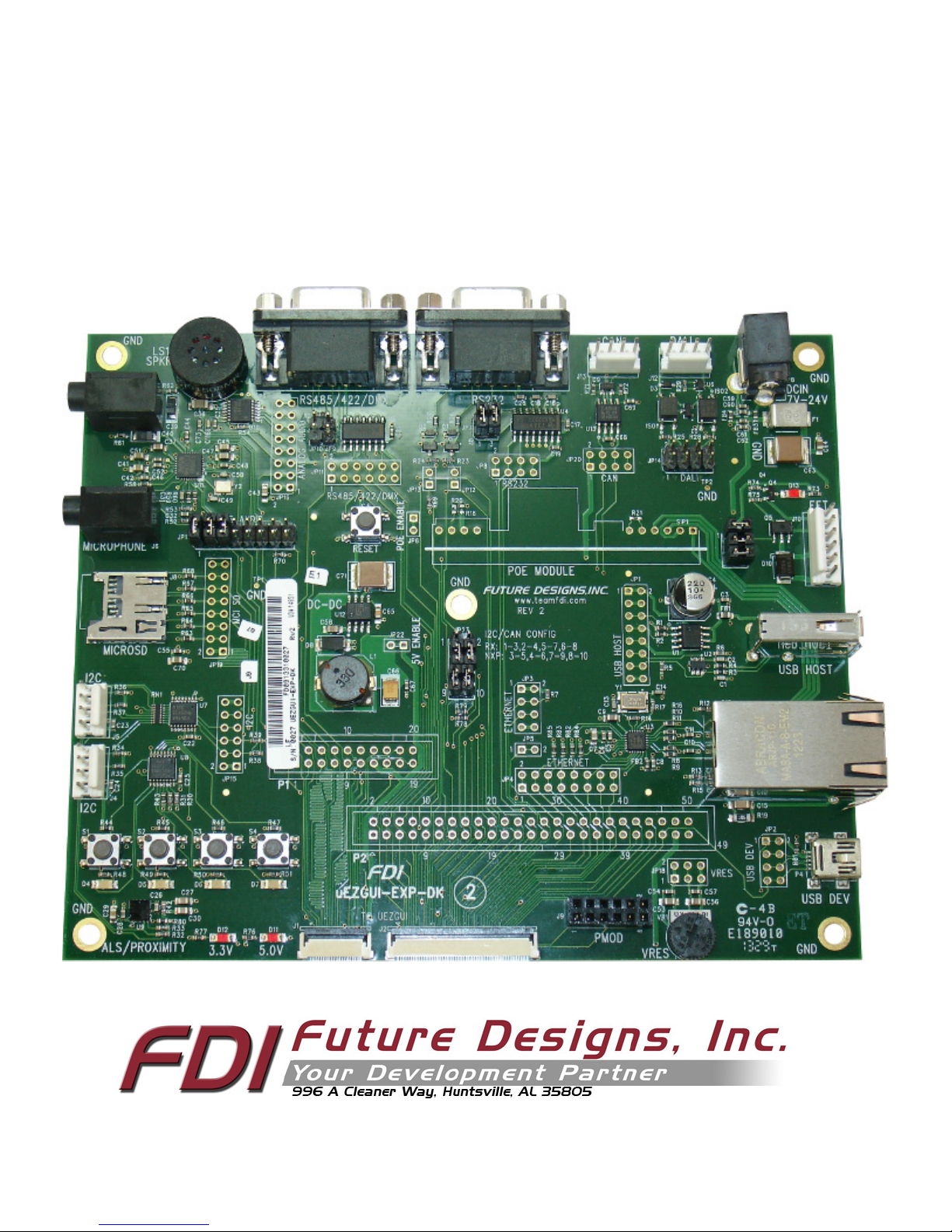
1. Introduction
The uEZGUI-EXP-DK is a quick and easy solution for rapid prototyping additional hardware with the uEZGUI family of
products. The uEZGUI-EXP-DK offers the hardware necessary for many different features.
2. Kit Contents
• uEZGUI-EXP-DK development expansion board
• 50 pin Flat Flexible Cable (FFC)
• 20 pin Flat Flexible Cable (FFC)
3. Functional Description
• RS232/RS485 Serial communication
• USB Host and Device
• 10/100 Ethernet
• Optional Power over Ethernet
• FET driver
• Potentiometer
• Optional DALI
• CAN
• I2S/DAC Audio (not supported on Renesas uEZGUIs)
• Built-in Speaker
• High –Speed 4 bit microSD card(not supported on Renesas uEZGUIs)
• I2C bus expander
• I2C GPIO with pushbuttons and LEDs
• I2C ALS/Proximity Sensor
• 70 Pin GPIO Expansion
• Ability to disconnect unused features
4. Requirements
The uEZGUI-EXP-DK comes with the necessary flex cables to begin development right away with the purchase of a
compatible uEZGUI kit. A 7V-24V power supply with a minimum of 1A current will be required to power the
uEZGUI-EXP-DK and connected uEZGUI. At this time, the uEZGUI-EXP-DK’s expansion pin configuration is compatible
with uEZGUIs based on the following microcontrollers:
• NXP LPC1788 (part numbers starting with uEZGUI-1788)
• NXP LPC2478 (part numbers starting with uEZGUI-2478)
• Renesas RX62N (part numbers starting with uEZGUI-RX62N)
With the 70 pin break-out and the ability to cut PCB traces, the uEZGUI-EXP-DK could be re-configured to support future
uEZGUIs, or to swap for the desired pins on existing uEZGUIs. Note that some features of the uEZGUI-EXP-DK will only
work with certain microcontrollers, such as the 4-bit microSD card slot and I2S audio.
1
5. ESD Warning
The uEZGUI-EXP-DK is shipped in a protective anti-static package. The device must not be subjected to high electrostatic
potentials. Damage may occur to the board that will not be covered under warranty. General practice for working with
static sensitive devices should be followed when working with the uEZGUI-EXP-DK.
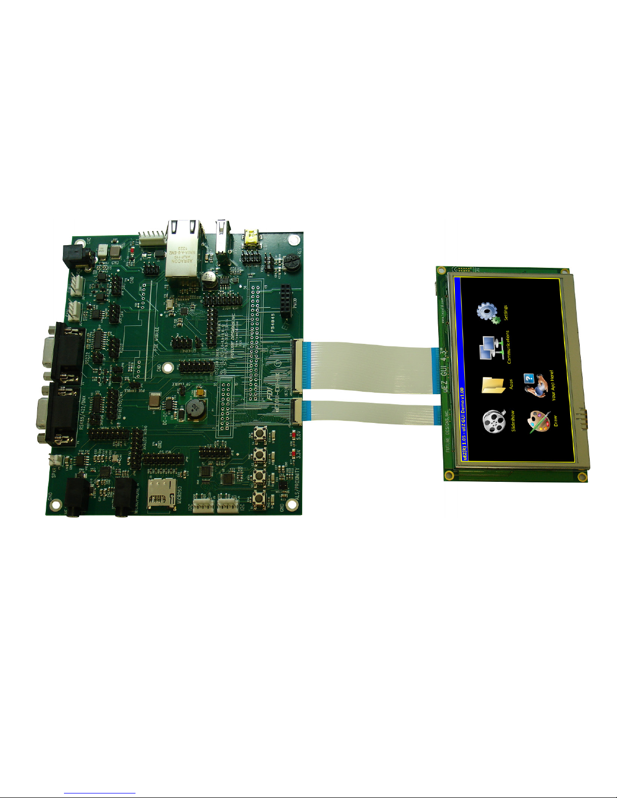
6. Startup Procedure
To get started with the uEZGUI-EXP-DK, please connect the 50 pin and 20 pin FFCs to the uEZGUI as shown. The uEZGUIRX62N-35QT does not support the 20 pin expansion. Take care not to damage the FFCs as they are very fragile.
uEZGUI-1788-43WQR with uEZGUI-EXP-DK (revision 1 is shown in this picture)
After connecting the cables, connect a 7V-24V DC power supply (minimum of 1A) to the 2.1mm barrel plug P8 on the
EXP-DK to power on the unit. With uEZ 2.05 or later, the EXP-DK will be auto-detected and the USB ports, Ethernet,
RS232, Audio, and high-speed microSD SD card will be automatically enabled. At this time the high speed microSD card is
only support on LPC1788 uEZGUI units. The out of the box demo does not include the video player. This will need to be
enabled inside of the project’s Config_Build.h file.
7. Mechanical Details
The uEZGUI-EXP-DK has 5 screw mounts that accept #6 size screws. The total board dimensions are 5” x 6”.
Each of the 4 corner screw mounts is centered 0.2” away from each side of the board.
2
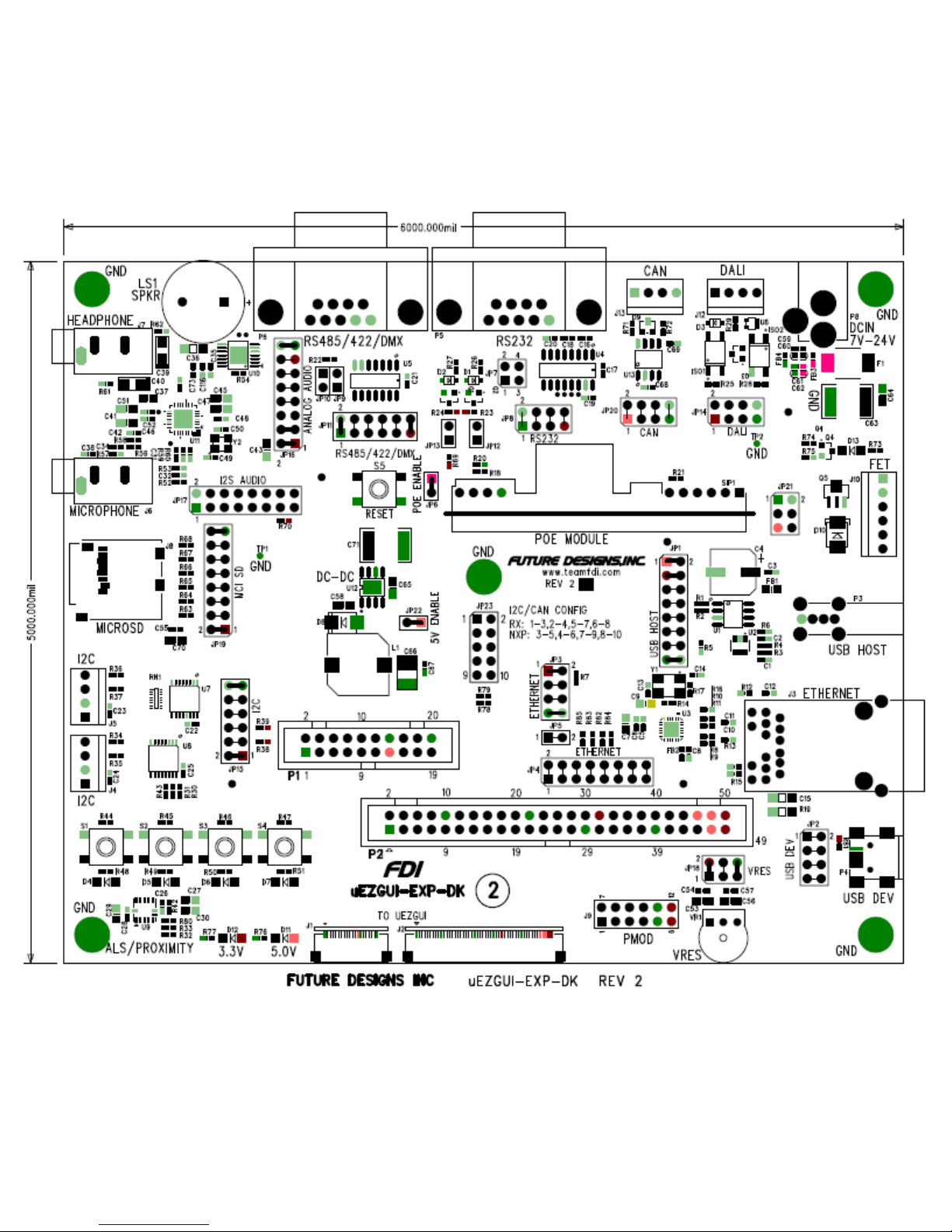
8. Expansion Board Top Level Mechanical Diagram / Board Layout
Below is the top level mechanical drawing of the uEZGUI-EXP-DK Rev 2 showing all of the part positions and silkscreen:
3
 Loading...