

Page 1
Version 3
F-DBS SAS
, La Maison des Services, Av des 2 Lacs, Courtabœuf 7, 91971 VILLEJUST
Tél: +33 1 64 86 25 40
Manual updates
Version
Date
1 10/03/11
2 20/03/11
3 10/04/11
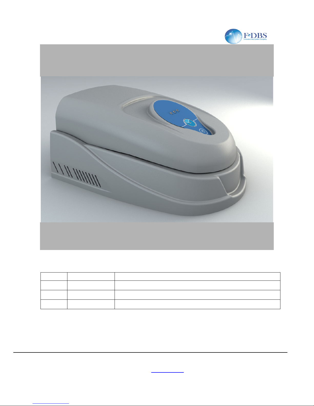
ZEROAIR User's Manual
- Fax: +33 1 69 31 23 01 - email: info@f-
dbs.com
Site web: www.f-dbs.com
1
ZEROAIR
User's Manual
Description
First draft
Update on figure dimensions and installations
Update reference to INLET and OUTLET
Page 2

Version 2
ZEROAIR User's Manual
F-DBS SAS
, La Maison des Services, Av des 2 Lacs, Courtabœuf 7, 91971 VILLEJUST
Tél: +33 1 64 86 25 40
INDEX
Introduction ................................
................................
Product Description
................................
Safety instruction
................................
Engineered System
................................
Air Supply ................................
................................
Dimensions and installation
................................
Dimensions ................................
................................
Installation ................................
................................
Overview and Connections
................................
User interface ................................
................................
FID Models ................................
................................
Maintenance ................................
................................
Quick Guide ................................
................................
First start-up ................................
................................
Turning off the machine
................................
Packaging ................................
................................
- Fax: +33 1 69 31 23 01 - email: info@f-
dbs.com
Site web: www.f-dbs.com
2
................................
................................
................................................................
................................
................................................................
................................
................................................................
................................
................................
................................
................................
................................
................................
................................
................................
................................
................................
................................
................................
................................
................................
................................
................................
................................
................................
................................
................................
................................
................................................................
................................
................................
................................
......................... 4
............ 4
................ 4
............ 5
........................... 5
................................ 6
......................... 6
........................... 6
................................. 7
..................... 8
......................... 9
..................... 10
...................... 11
...................... 11
.... 11
......................... 11
Page 3

Version 2
ZEROAIR User's Manual
F-DBS SAS
, La Maison des Services, Av des 2 Lacs, Courtabœuf 7, 91971 VILLEJUST
Tél: +33 1 64 86 25 40
1 Introduction
This manual is intended to provide technical guidance on the installation, operation and maintenance of zero
air generator. Do not attempt to in
stall or operate this product without having fully read and understood the
information presented. If you have questions, please contact your local supplier.
WARNING: Any misuse of this product will avoid the manufacturer ’s warranty
2 Product
Description
This series of Zero Air Generators are systems which replace the use of inconvenient high pressure gas
cylinders as a source of hydrocarbon
managing them and reduces the ris
k of possible injury to workers
•
Zero Air Generator may be used as a source of fuel air for Flame Ionization Detectors (FID’s) or as a
zero reference for any instrument which measures hydrocarbon concentration.
•
The zero air generator will remove HC polluta
•
This system is engineered to be easy to install, need a low and requires only minimal annual
maintenance.
3 Safety instruction
Do not use the unit until the safety information and instructions in this guide have been read and
Using equipment in a manner not specified in this document may compromise the protection provided by the
generator and could lead to an unplanned release of pressure, which may cause serious personal injury or
damage.
• Read all instructions.
• C
ontact your supplier if you detect a problem that you cannot solve with this manual.
•
This equipment is for internal use only. Do not use outdoors.
•
The operator must employ safe working practices and rules when operating the Zero Air Generator.
• The owner is
responsible for maintaining the unit in a safe operating condition.
•
Always use approved parts when performing maintenance and repairs. Make sure that replacement
parts meet or exceed the pressure requirements.
•
Only authorized, trained and competent indi
•
Completely depressurize the generator prior to performing any mechanical work, including changing
the filters.
•
Do not open the generator while the machine is operating.
•
Care must be taken as burns can occur from
•
Do not operate equipment with a damaged cord or if the equipment has been dropped or damaged
until it has been examined by a qualified serviceman.
•
Let equipment cool completely before to move or close in a box
• To reduce the risk of fir
e, do not operate equipment in the vicinity of open containers of flammable
liquids.
NOTE : It is no possible to anticipate every possible circumstance that may constitute a potential danger. The
warnings in the manual cover potential dangers best known,
SAVE THESE INSTRUCTIONS
- Fax: +33 1 69 31 23 01 - email: info@f-
dbs.com
Site web: www.f-dbs.com
3
-
free air. Eliminate gas cylinders reduces annual operating costs of
nts to less than 0.05 ppm.
viduals must perform maintenance and repair.
touching hot parts.
but by definition can not be all
understood.
-inclusive.
Page 4

Version 2
ZEROAIR User's Manual
F-DBS SAS
, La Maison des Services, Av des 2 Lacs, Courtabœuf 7, 91971 VILLEJUST
Tél: +33 1 64 86 25 40
4
Engineered System
Basic diagram (Figure 1)
The system consist in 3 stage of filtration :
Fisrt Stage
: high efficiency coalescing prefiltration, it removes liquids and particula
incoming air supply, to 5 micron.
These filters are equipped with float drains which automatically open to empty any liquids from inside the
filter housing. The drains are connected to 1/4" tubing which discharges to atmosphere
Second Stage
: The catalyst module is a stainless steel vessel filled with catalyst and assembled with a
cartridge heater controlled by temperature sensor and operates the catalyst bed at the required temperature
for optimal oxidation. During operation, hydrocarb
Third Stage :
High-
grade filter is used to remove 99.99% of particulates with size greater than 0.5 microns.
5 Air Supply
The Zero Air Generator requires a source of clean, dry compressed air (3 to 8 Ba
air should be as close to instrument quality as possible and supplied at a flow rate and pressure above those
required at the point of use.
Air supplied to the Generator must be between 35°C (95°F) and 1°C (34°F) at dewpoint <
temperatures higher or lower or to much wet than this may cause damage not covered by warranty.
The air should be relatively free of compressor oil, hydrocarbons, and particulate matter max 100ppm.
Contamination of the catalyst bed may occ
- Fax: +33 1 69 31 23 01 - email: info@f-
dbs.com
Site web: www.f-dbs.com
4
ons are oxidized into carbon dioxide and water vapor.
r) for optimal operation. The
ur if it is exposed to certain compounds.
te matter, from the
-20°C. Air at
Page 5
Version 2
ZEROAIR User's Manual
F-DBS SAS
, La Maison des Services, Av des 2 Lacs, Courtabœuf 7, 91971 VILLEJUST
Tél: +33 1 64 86 25 40
6
Dimensions and installation
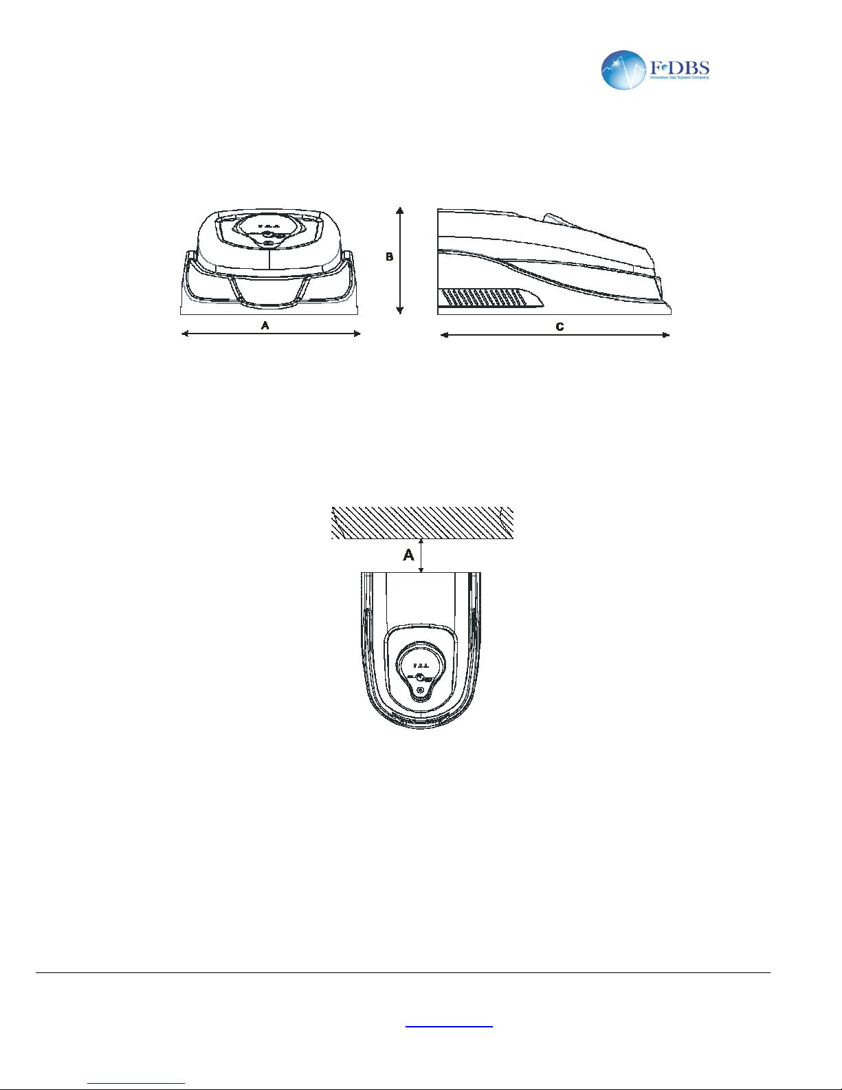
6.1 Dimensions
A = 34cm (13”)
B = 20cm (7.9”)
C = 43cm (16,9”)
6.2 Installation
Figure 2
A > 15cm (6”)
In order to ensure safe operation of the unit, the following steps must be taken
installation:
1.
At least 6” (150 mm) clearance at the back for proper fan operation.
2.
Adequate support for the weight (>10 kg.).
3.
Access at the rear for making the pneumatic and electrical connections.
- Fax: +33 1 69 31 23 01 - email: info@f-
dbs.com
Site web: www.f-dbs.com
5
prior to
Page 6
Version 2
ZEROAIR User's Manual
F-DBS SAS
, La Maison des Services, Av des 2 Lacs, Courtabœuf 7, 91971 VILLEJUST
Tél: +33 1 64 86 25 40
6.3
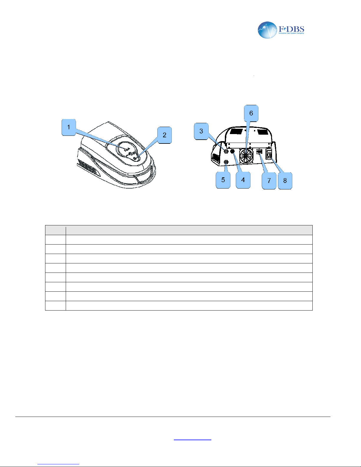
Overview and Connections
All connections,
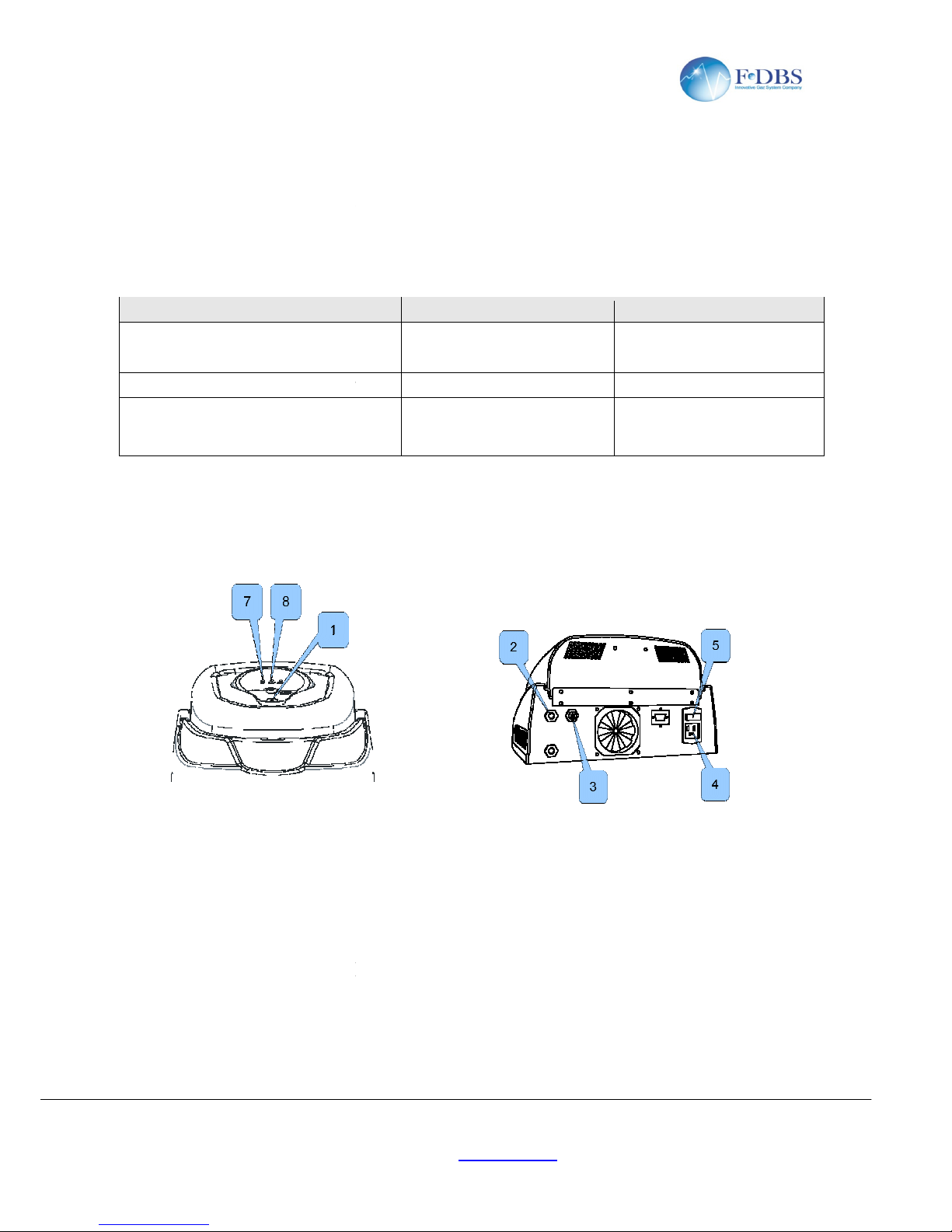
electric and pneumatic, are made at the back panel. Refer to follow Figure 3
Front view (Figure 3)
Description
1 Status leds
2 START/STOP Button
3 AIR outlet
4 Compress AIR inlet
5 WATER DRAIN purge
6 Cooling fan air (intake)
7 RS485 (optional)
8
Power Switch and power socket
Make the following pneumatic connections:
•
AIR INLET (1/8” female pipe thread)
•
AIR OUTLET (1/8” female pipe thread)
Keep this line as short as possible to minimize pressure drops
• WATER
DRAIN Connect a 6mm(1/4”) diameter tubing to the water out fitting to avoid the occasional
spurts of water on the instrument under. Connect the other end of the tubing to a drain or, alternatively, the
water can be collected in a tray or bucket and disper
Make the following pneumatic connections
•
POWER. Connect the power cord to the proper power source.
•
COMMUNICATION : connect the communication cable to the control unit (if need)
- Fax: +33 1 69 31 23 01 - email: info@f-
dbs.com
Site web: www.f-dbs.com
6
Back view (Figure 4)
sed by normal evaporation.
-4.
Page 7
Version 2
ZEROAIR User's Manual
F-DBS SAS
, La Maison des Services, Av des 2 Lacs, Courtabœuf 7, 91971 VILLEJUST
Tél: +33 1 64 86 25 40
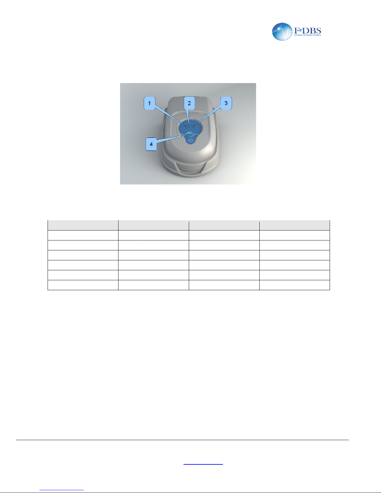
7 User interface
Figure 6
The front panel has th
ree LEDs : GREEN (1), YELLOW (2), RED(3) and a one button (4). Pressing
START/STOP button (1) you can turn on or off / warming oven catalyst. The following table show the link
between led's state and unit's state.
Status
Green Led(1)
STOP
COOLING DOWN
FLASHING
WARMING UP
READY
ALARM
CATALYST EXAUSTED
8
- Fax: +33 1 69 31 23 01 - email: info@f-
dbs.com
Site web: www.f-dbs.com
7
Yellow Led(2)
ON OFF
OFF
ON FLASHING
ON ON
X X
X X
Red Led
(3)
OFF
OFF
OFF
OFF
FLASHING
ON
Page 8
Version 2
ZEROAIR User's Manual
F-DBS SAS
, La Maison des Services, Av des 2 Lacs, Courtabœuf 7, 91971 VILLEJUST
Tél: +33 1 64 86 25 40
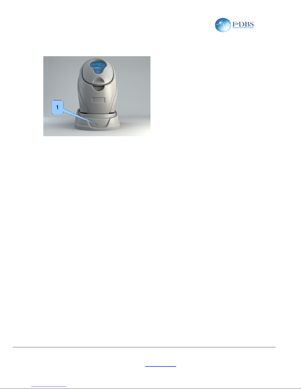
9 FID Models
- Fax: +33 1 69 31 23 01 - email: info@f-
dbs.com
Site web: www.f-dbs.com
8
The FID Models are without the top cover and it can
be put under the H2 generator of the same
line. Once the special cable is connected between
both the units the control of ZEROAIR module is
transferred to the generator H2. The operator can
control ZEROAIR unit by the H2 user interface.
product
Page 9
Version 2
ZEROAIR User's Manual
F-DBS SAS
, La Maison des Services, Av des 2 Lacs, Courtabœuf 7, 91971 VILLEJUST
Tél: +33 1 64 86 25 40
10 Maintenance
All maintenance procedures should be p
Prior to servicing Zero Air Generator, turn off the compressed air and power supplies to the generator, and
ensure that the system is depressurized.
To ensure consistent product performance and reliabi
filter cartridges.
The primary maintenance tasks required are :
Operation
Changing the high efficiency coalescing
prefilter cartridges
Changing the High-grade filter
cartridges
Replacing the catalyst oven
11 Quick Guide
11.1 First start-up
Figure 7
List of the
operations to be performed for first start
Connect the hose to the AIR inlet fitting (3).
Connect the hose to the AIR outlet fitting (2)
Connect the voltage wire to the power socket (4).
Turn on the power switch (5).
Start the internal oven heating pre
Wait until the yellow LED will be solid(8)
11.2
Turning off the machine
List of the operations to be performed before turning off the back power switch
Stop the internal oven heating pressing START/STOP button(6).
- Fax: +33 1 69 31 23 01 - email: info@f-
dbs.com
Site web: www.f-dbs.com
9
erformed by suitable personnel using reasonable care.
lity use only genuine Balston replacement parts and
Interval
KIT parts ordering code
Every year
SP.ZA.FILTER
Every year
SP.H2.WFILT.M
When the Red Led is solid on
SP.ZA.SKIT1 for 1,5 L/in
SP.ZA.SKIT3 for 3,5 L/in
SP.ZA.SKIT6 for 6,0 L/in
-up
ssing START/STOP button(1).
Page 10
Version 2
ZEROAIR User's Manual
F-DBS SAS
, La Maison des Services, Av des 2 Lacs, Courtabœuf 7, 91971 VILLEJUST
Tél: +33 1 64 86 25 40
Turn off the
power switch (5).
11.3 Packaging
List of the operations to be performed before packing the machine to return it for maintenance service:
Stop the internal oven heating pressing START/STOP button(1).
Wait until Green led will be solid(7)
Turn off the power switc
h (5).
Disconnect the power cable from the voltage socket (4)
Disconnect the AIR's hose from the feed fitting (2).
Place the generator in its special packaging.
The generator contains Hot elements. Ensure that it is fully cooled prior to shipment or
servicing.
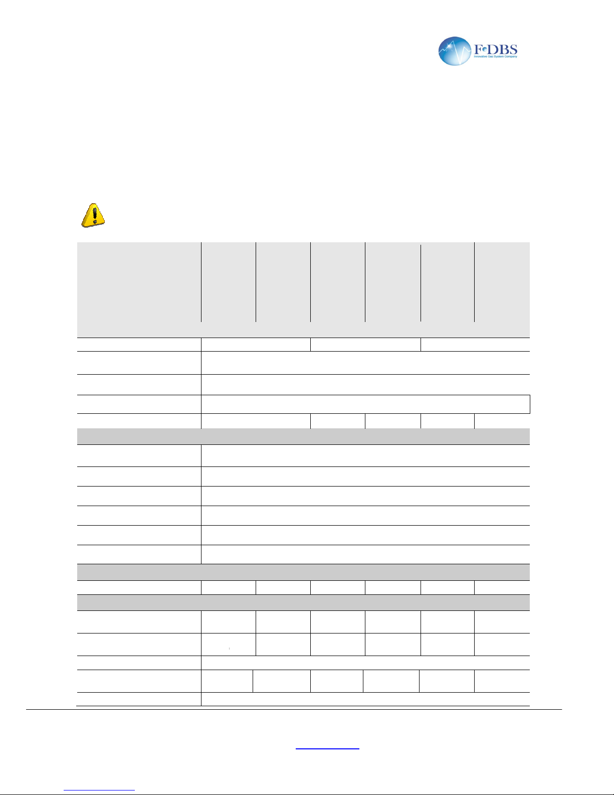
Models
Z.
-
1500
Air outlet
Flow rate (max)
OUTLET pressure (min)
OUTLET pressure (max)
Total hydrocarbon content
Startup time
Air inlet
Max inlet hydrocarbon content
Min Supply Pressure
Max Supply Pressure
Dewpoint
Min Temperature
Max Temperature
Communication
RS485
Option
General data
Connection type
IC320
Supply voltage 90-
240Vac
50/60Hz
Installation Power (max)
Fuse Rating (230V)
(110V)
2A(5x20mm)
Dimensions
- Fax: +33 1 69 31 23 01 - email: info@f-
dbs.com
Site web: www.f-dbs.com
10
Z.
-
1500
ZA.FID.1500
ZA.3000
ZA.FID.3000
1,5 l/min 3,0 l/min
Pressure INLET –
0.5 Bar (8 psi) at maximum flow
6.5 Bar(94 psi)
< 0.05ppm
40 min 45 min 45 min
100ppm
3 Bar (43psi)
10 Bar (145 psi)
< -20°C
1°C (34°F)
35°C(95°F)
X Option X
-C13 4 pole
connector
IC320-C13 4 pole
connector
24VDC
± 5%
90-240Vac
50/60Hz
24VDC
± 5%
240W (280VA)
Internal 2A
(5x20mm)
Internal
43x34x20(H) cm
ZA.6000
ZA.FID.6000
6,0 l/min
50 min 50 min
Option X
IC320-C13 4 pole
connector
90-240Vac
50/60Hz
24VDC
± 5%
2A
(5x20mm)
internal
Page 11
Version 2
ZEROAIR User's Manual
F-DBS SAS
, La Maison des Services, Av des 2 Lacs, Courtabœuf 7, 91971 VILLEJUST
Tél: +33 1 64 86 25 40
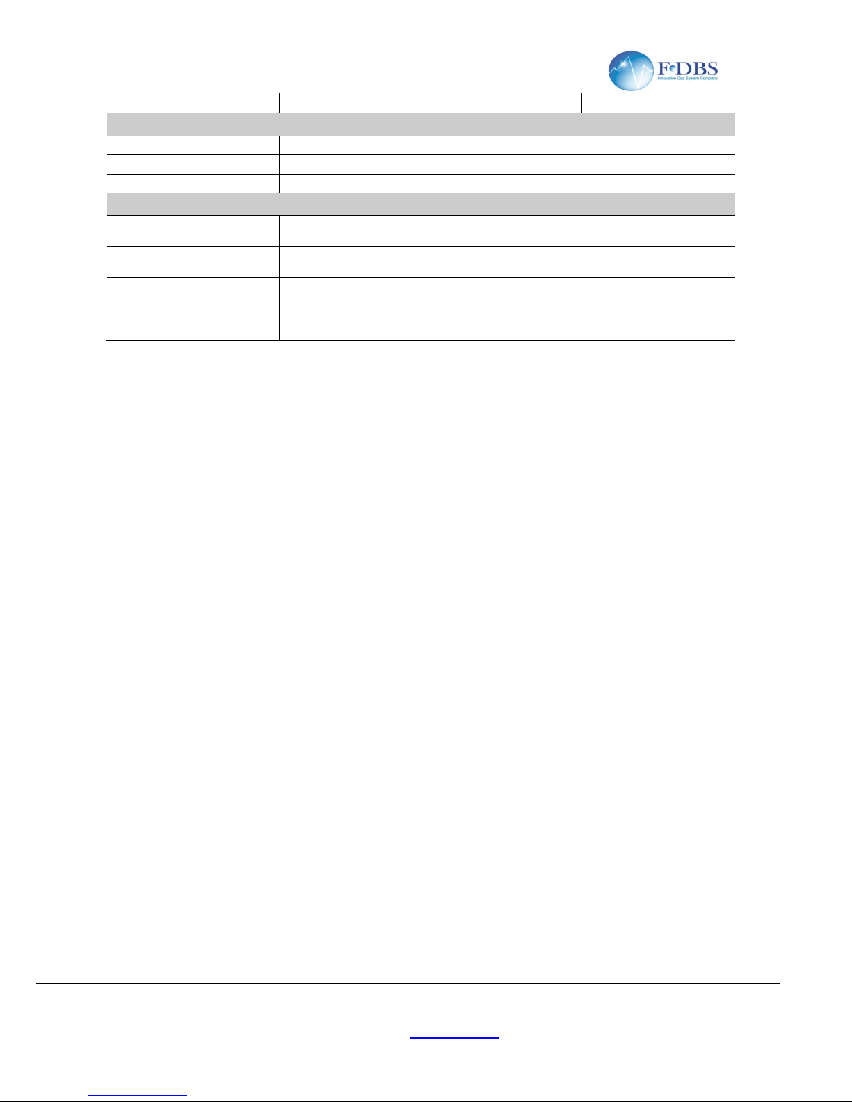
Net weight(water tank empty)
Connections
Outlet port
Inlet port
Water purge
Ambient data
Temperature
Humidity (max, non condensing)
Noise
IP rating
- Fax: +33 1 69 31 23 01 - email: info@f-
dbs.com
Site web: www.f-dbs.com
11
8Kg
1/8" Female
1/8" Female
6mm(1/4) push fitting
5-35°C (41-95°F)
80% at 25°C (77°F)
<25dB(A)
IP20
9Kg
Page 12

Version 2
ZEROAIR User's Manual
F-DBS SAS
, La Maison des Services, Av des 2 Lacs, Courtabœuf 7, 91971 VILLEJUST
Tél: +33 1 64 86 25 40
NOTE :
- Fax: +33 1 69 31 23 01 - email: info@f-
dbs.com
Site web: www.f-dbs.com
12
 Loading...