

Page 1
MODEL
• DYNA TWC 901
• DYNA TWC 902
Operating Manual
(Owner’s Manual)
IMPORTANT: Read these instructions before installing, operating, or servicing this system.
First Edition Manual No. ET001
Page 2

Page 3

- 1 -
DYNA TWC 901、902 Operating Manual
CONTENTS
SYMBOL LEGEND---------------------------------------------------------------------------------------------------2
STATEMENT OF WARRANTY------------------------------------------------------------------------------------3
1.0 GENERAL INFORMATION-------------------------------------------------------------------------------4
1.01 Notes, Cautions and W arnings------------------------------------------------------------------------4
1.02 Important Safety Precautions--------------------------------------------------------------------------4
1.03 Transporting methods-----------------------------------------------------------------------------------6
2.0 INSTALLATION RECOMMENDATION----------------------------------------------------------------7
3.0 OPERATOR CONTROLS---------------------------------------------------------------------------------8
4.0 SPECIFICATIONS------------------------------------------------------------------------------------------9
5.0 PARTS LIST--------------------------------------------------------------------------------------------------9
6.0 REMARK-----------------------------------------------------------------------------------------------------12
Page 4
- 2 -
DYNA TWC 901、902 Operating Manual
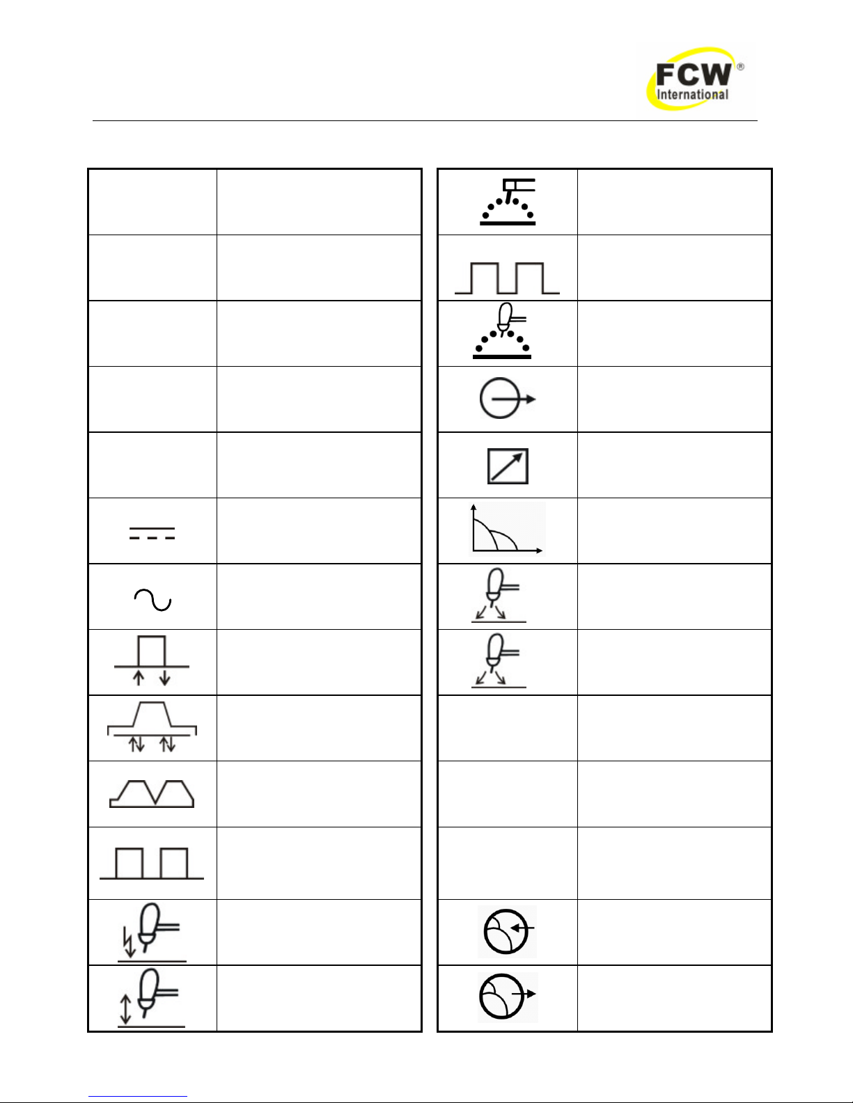
SYMBOL LEGEND
A
Amperage
Stick (SMAW)
V
Voltage
Pulse Current Function
(GTAW)
Hz
Hertz (frequency)
t
Spot Time (GTAW)
SEC
Seconds
Remote outputs control
(Panel/Remote)
%
Percent
Remote Function
DC (Direct Current )
Arc Control (SMAW)
AC (Alternating Current )
t
2
Gas Post-Flow Time
2T (GTAW)
t
1
Gas Pre-Flow Time
4T (GTAW)
VRD
Voltage Reduction
Device Circuit
Repeat Function (GTAW)
—
Negative
Spot Function (GTAW)
+
Positive
High Frequency Starting
(GTAW)
Gas Input
Lift Start (GTAW)
Gas Output
Page 5

- 3 -
DYNA TWC 901、902 Operating Manual
STATEMENT OF WARRANTY
LIMITED WARRANTY: "FCW" warrants to customers of its authorized distributors hereafter "FCW" that its products will be free
of defects in workmanship or material. Should any failure to conform to this warranty appear within the time period applicable to
the FCW products as stated below, FCW shall, upon notification thereof and substantiation that the product has been stored,
installed, operated, and maintained in accordance with FCW’s specifications, instructions, recommendations and recognized
standard industry practice, and not subject to misuse, repair, neglect, alteration, or accident, correct such defects by suitable
repair or replacement, at FCW ‘s sole option, of any components or parts of the product determined by FCW to be defective.
The FCW COMPANY MAKES NO OTHER WARRANTY, EXPRESS OR IMPLIED. THIS WARRANTY IS EXCLUSIVE AND IN
LIEU OF ALL OTHERS, INCLUDING, BUT NOT LIMIT ED TO ANY WARRANTY OF MERCHANTABILITY OR FITNESS FOR
ANY PARTICULAR PURPOSE.
LIMITATION OF LIABILITY: FCW shall not under any circumstances be liable for special, indirect or consequential damages,
such as, but not limited to, lost profits and business interruption. The remedies of the Purchaser set forth herein are exclusive
and the liabil ity of FCW with respect to any contract, or anything done in connection therewith such as the performance or
breach thereof, or from the manufacture, sale, delivery, resale, or use of any goods covered by or furnished by FCW whether
arising out of contract, negligence, strict tort, or under any warranty, or otherwise, shall not, except as expressly provided herein,
exceed the price of the goods upon which such liability is based. No employee, agent, or representative of FCW is authorized to
change this warranty in any way or grant any other warranty.
PURCHASER'S RIGHTS UNDER THIS WARRANTY ARE VOID IF REPLACEMENT PARTS OR ACCESSORIES ARE USED
WHICH IN FCW’S SOLE JUDGEMENT MAY IMPAIR THE SAFETY OR PERFORMANCE OF ANY FCW PRODUCT.
PURCHASER'S RIGHTS UNDER THIS WARRANTY ARE VOID IF THE PRODUCT IS SOLD TO PURCHASER BY
NON-AUTHORIZED PERSONS.
The warranty is effective for the time stated below beginning on the date that the authorized distributor delivers the products to
the Purchaser. Not with standing the foregoing, in no event shall the warranty period extend more than the time stated plus one
year from the date FCW delivered the product to the authorized distributor.
POWER SUPPLIES POWER SUPPLIES & WIRE FEEDERS
MAIN POWER MAGNETICS (STATIC& ROTATING) 1YEAR
ORIGINAL MAIN POWER RECTIFIER 1YEAR
POWER SWITCHING SEMI-CONDUCTORS & CONTROL PC BOARD 1YEAR
ALL OTHER CIRCUITS AND COMPONENTS INCLUDING 1YEAR
BUT NOT LIMITED TO, CONTACTORS, RELAYS,
SOLENOIDS, PUMPS, SWITCHES, MOTORS
Warranty repairs or replacement claims under this limited warranty must be submitted to FCW by an authorized FCW repair
facility within thirty (30) days of purchaser’s notice of any Warranty Claim. No transportation costs of any kind will be paid under
this warranty. Transportation charges to send products to an authorized warranty repair facility shall be the responsibility of the
Purchaser. All returned goods shall be at the Purchaser’s risk and expense. This warranty supersedes all previous FCW
warranties.
Page 6
- 4 -
DYNA TWC 901、902 Operating Manual
1.0 GENERAL INFORMATION
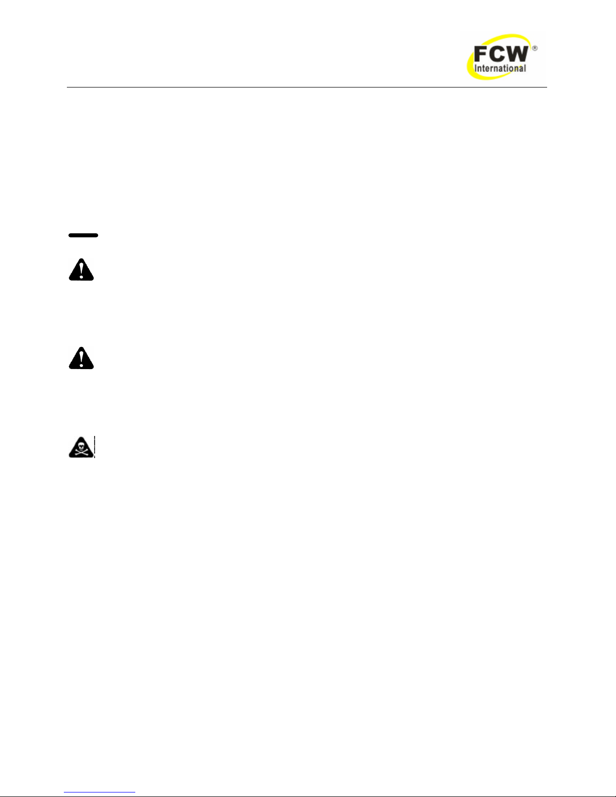
1.01 Notes, Cautions and W arnings
Throughout this manual, notes, cautions, and warnings are used to highlight important information. These
highlights are categorized as follows:
NOTE
An operation, procedure, or background information which requires additional emphasis or is helpful in
efficient operation of the system.
CAUTION
A procedure which, if not properly followed, may cause damage to the equipment.
WARNING
A procedure which, if not properly followed, may cause injury to the operator or others in the operating area.
1.02 Important Safety Precautions
WARNING
OPERATION AND MAINTENANCE OF ARC WELDING EQUIPMENT CAN BE DANGEROUS AND
HAZARDOUS TO YOUR HEALTH.
To prevent possible injury, read, understand and follow all warnings, safety precautions and instructions
before using the equipment. Call 86-21-69171135 or your local distributor if you have any questions.
GASES AND FUMES
Gases and fumes produced during the Arc welding or cutting process can be dangerous and hazardous to
your health.
l Keep all fumes and gases from the breathing area. Keep your head out of the welding fume plume.
l Use an air-supplied respirator if ventilation is not adequate to remove all fumes and gases.
l The kinds of fumes and gases from the arc welding/cutting depend on the kind of metal being used,
coatings on the metal, and the different processes. You must be very careful when cutting or welding
any metals which may contain one or more of the following:
Antimony Arsenic Barium Beryllium Cadmium Chromium Cobalt Copper Lead
Manganese Mercury Nickel Selenium Silver Vanadium
l Always read the Material Safety Data Sheets (MSDS) that should be supplied with the material you
are using. The se MSDSs will give you the information regarding the kind and amount of fumes and
gases that may be dangerous to your health.
l Use special equipment, such as water or down draft welding/cutting tables, to capture fumes and
gases.
l Do not use the welding torch in an area where combustible or explosive gases or materials are
located.
l Phosgene, a toxic gas, is generated from the vapors of chlorinated solvents and cleansers. Remove
all sources of these vapors.
Page 7
- 5 -
DYNA TWC 901、902 Operating Manual
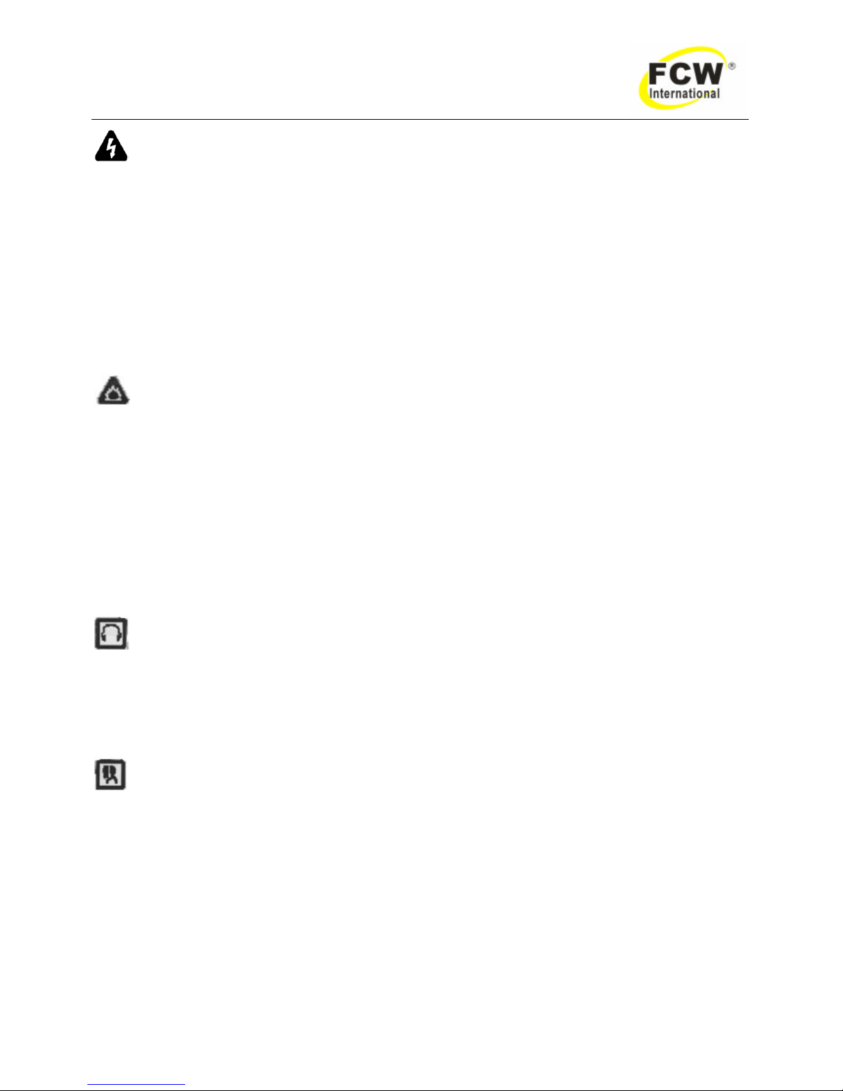
ELECTRIC SHOCK
Electric Shock can injure or kill. The arc welding process uses and produces high voltage electrical energy.
This electric energy can cause severe or fatal shock to the operator or others in the workplace.
l Never touch any parts that are electrically “live” or “hot.”
l Wear dry gloves and clothing. Insulate yourself from the work piece or other parts of the welding
circuit.
l Repair or replace all worn or damaged parts.
l Extra care must be taken when the workplace is moist or damp.
l Install and maintain equipment according to NEC code, refer to relative standards
l Disconnect power source before performing any service or repairs.
l Read and follow all the instructions in the Operating Manual.
FIRE AND EXPLOSION
Fire and explosion can be caused by hot slag, sparks, or the arc weld.
l Be sure there is no combustible or flammable material in the workplace. Any material that cannot be
removed must be protected.
l Ventilate all flammable or explosive vapors from the workplace.
l Do not cut or weld on containers that may have held combustibles.
l Provide a fire watch when working in an area where fire hazards may exist.
l Hydrogen gas may be formed and trapped under aluminum workpieces when they are cut
underwater, or while using a water table. Do not cut aluminum alloys underwater or on a water table
unless the hydrogen gas can be eliminated or dissipated. Trapped hydrogen gas that is ignited will
cause an explosion.
NOISE
Noise can cause permanent hearing loss. Arc welding/cutting processes can cause noise levels to exceed
safe limits. You must protect your ears from loud noise to prevent permanent loss of hearing.
l To protect your hearing from loud noise, wear protective ear plugs and/ or ear muffs. Protect others
in the workplace.
l Noise levels should be measured to be sure the decibels (sound) do not exceed safe levels.
ARC WELDING RAYS
Arc Welding/ Cutting Rays can injure your eyes and burn your skin. The arc welding/cutting process produces
very bright ultra violet and infra red light. These arc rays will damage your eyes and burn your skin if you are
not properly protected.
l To protect your eyes, always wear a welding helmet or shield. Also always wear safety glasses with
side shields, goggles or other protective eye wear.
l Wear welding gloves and suitable clothing to protect your skin from the arc rays and sparks.
l Keep helmet and safety glasses in good condition. Replace lenses when cracked, chipped or dirty.
l Protect others in the work area from the arc rays. Use protective booths, screens or shields.
Page 8
- 6 -
DYNA TWC 901、902 Operating Manual
1.03 Transporting methods
These units are equipped with a handle for carrying purposes.
WARNING: ELECTRIC SHOCK can kill.
DO NOT TOUCH live electrical parts. Disconnect input power conductors from de-energized supply
line before moving the welding power source.
WARNING: FALLING EQUIPMENT can cause serious personal injury and
equipment damage.
l Lift unit with handle on top of case.
l Use handcart or similar device of adequate capacity.
l If using a fork lift vehicle, place and secure unit on a proper skid before transporting.
Page 9

- 7 -
DYNA TWC 901、902 Operating Manual
2.0 INSTALLATION RECOMMENDATION
Installation Environment
DYNA TWC series is designed for use in hazardous environments.
Examples of environments with increased hazardous environments are -
In locations in which freedom of movement is restricted, so tha t the operator is forced to perform the work
in a cramped (kneeling, sitting or lying) position with physical contact with conductive parts; In locations which
are fully or partially limited by conductive elements, and in which there is a high risk of unavoidable or
accidental contact by the operator, or in wet or damp hot locations where humidity or perspiration
considerable reduces the skin resistance of the human body and the insulation properties of accessories.
Environments with hazardous environments do not include places where electrically conductive parts in
the near vicinity of the operator, which can cause increased hazard, have been insulated.
Installation Location
Be sure to locate the welder according to the following guidelines:
l In areas, free from moisture and dust.
l In areas, free from oil, steam and corrosive
gases.
l In areas, not exposed to direct sunlight or rain.
l Ambient temperature: between -10 degrees C
to 40 degrees C.
l In areas, not subjected to abnormal vibration or
shock.
l Place at a distance of 304.79mm or more from
walls or similar that could restrict natural airflow
for cooling.
WARNING 1
FCW advises that this equipment be electrically connected by a qualified electrician.
Page 10
- 8 -
DYNA TWC 901、902 Operating Manual
3.0 OPERATOR CONTROLS
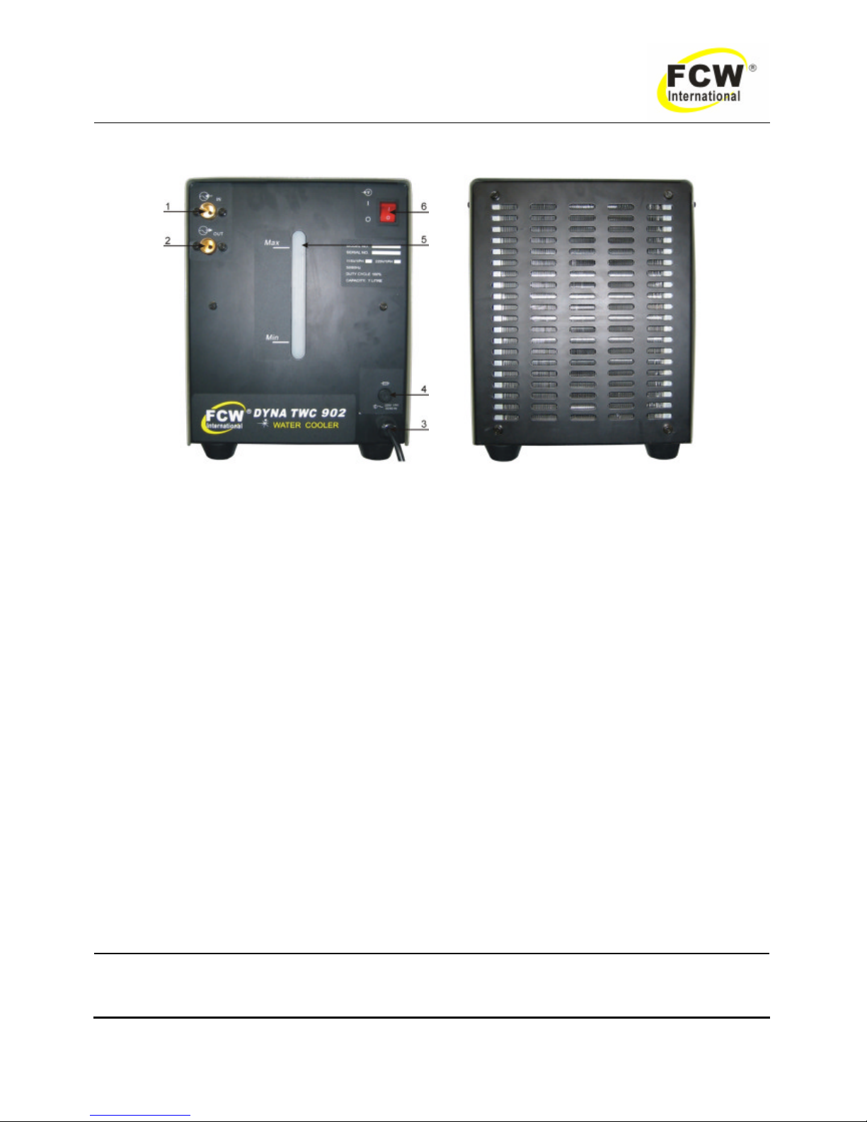
Figure 1
1. Input Water Fitting—Fitting size 5/8” – 18 LH female.
2. Output Water Fitting—Fitting size 5/8” – 18 LH female.
3. Input Cable— 3 meter.
4. Fuse
5. Water Reading
6. Main Power Switch— Switching to the ON position power source.
WARNING
When the welder is connected to the primary supply voltage, the internal electrical
components maybe at primary potential with respect to earth.
Page 11
- 9 -
DYNA TWC 901、902 Operating Manual
4.0 SPECIFICATIONS
MODEL TWC 901 TWC 902
Input Voltage 110V 1ph 50 /60Hz 220V 1ph 50 /60Hz
Input Current 3.4A 1.7A
Duty Cycle (40ºC) 100% 100%
Flow 3.0L/min 3.0L/min
Pressure 0.121MPa 0.121MPa
Capacity 7Litre 7Litre
Weight 15kg 15kg
Dimensions (mm) 530*260*320mm 530*260*320mm
Table 1
5.0 PARTS LIST
Page 12
- 10 -
DYNA TWC 901、902 Operating Manual
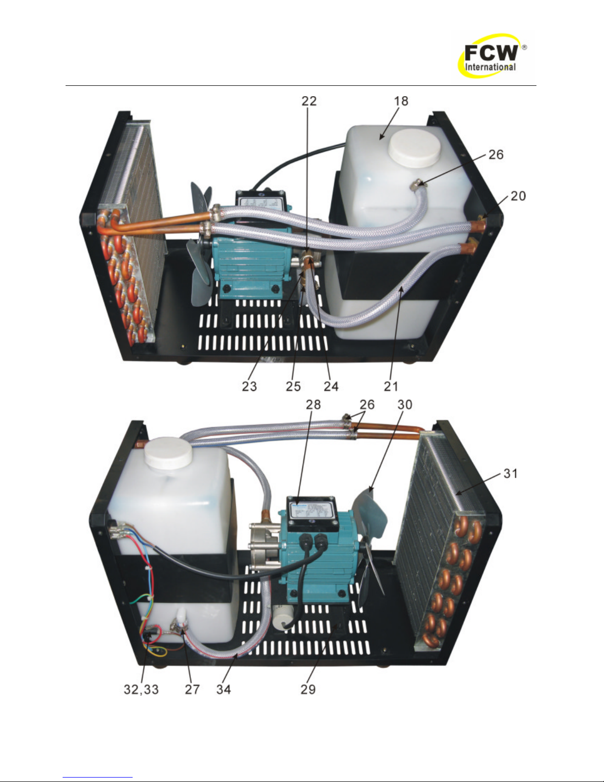
Figure 2
Page 13
- 11 -
DYNA TWC 901、902 Operating Manual
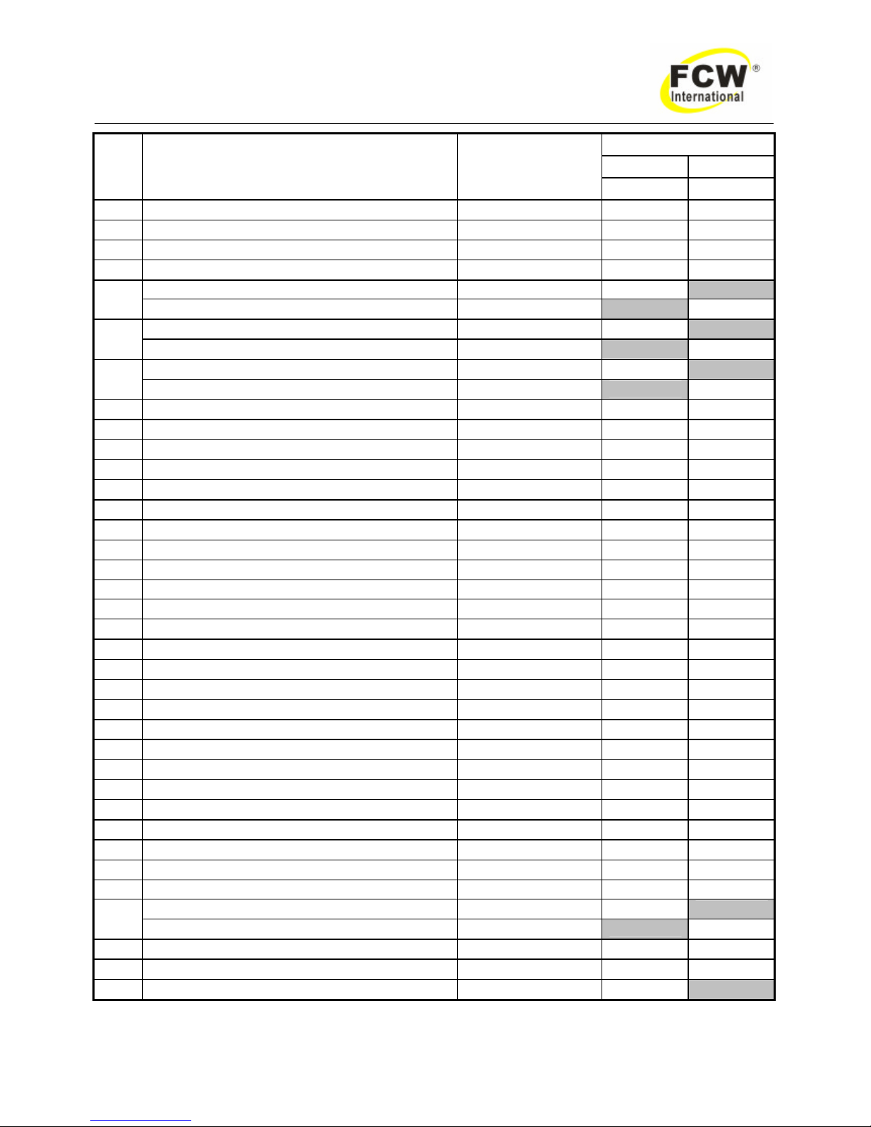
QTY.
TWC 901 TWC 902
Sequ
ence
Name Order No
P/N: 638003999 P/N: 638004999
1 LABEL In/Out TWC902 2LAU8801000 1 1
2 LABEL WATER LEVEL TWC 801/802/901/902 2LAX8804000 1 1
3 LABEL MAIN SWITCH TWC 801/802/901/902 2LAX8806007 1 1
4 LABEL MANUFACTURERS RATING TWC 2LAN8808011 1 1
LABEL FUSE TWC 901 2LAX 8806009 1
5
LABEL FUSE TEC 902 2LAX8806008 1
LABEL VOLTAGE INPUT 115V 1PH 2LAM8806008 1
6
LABEL VOLTAGE INPUT 220V 1PH 2LAM8800005 1
LABEL FRONT TWC 901 2LAF8802006 1
7
LABEL FRONT TWC 902 2LAF8802007 1
8 LABEL FCW(SMALL) 2LAS8802013 2 2
9 LABEL WARNING 127*70 2LAW8805000 1 1
10 SWITCH KCD2-21 16A 4KCD221RD 1 1
11 BUSHING,STRAIN RELIEF PG11 4SXJPG11 1 1
12 HANDLE 160/200 4HDL00001 1 1
13 PANEL TOP FP8.040.008GJ 2FPPT8040008GJ 1 1
14 SCREW BLACK M4*10 5FPS8918000 16 16
15 SCREW STAINLESS STEEL M5*16 5GBTBYTM5X16 2 2
16 BASE TWC901/902 FP8.032.006 2FPB8032006 1 1
17 MOUNT NPRN JJ60 4JFT35X50 1 1
18 water tank 30*17*15 4WER30X17X15 1 1
19 BRACKET WATER TANK FP8.038.007 2FPBM8038007 1 1
20 HOSE FITTING(A) FP8.653.014 2AD8653014 2 2
21 HOSE WATER 8*13 8HPVCG8X13 1m 1m
22 ADAPTORS 2ADEI0001 1 1
23 ADAPTORS L-PIECE 2ADEL0001 1 1
24 HOSE FITTING 1/8 2ADHF33X8R5002 1 1
25 HOSE FITTING 1/4 2ADHF8653016 1 1
26 HOSE CLAMP 13.5*19 2HFP8636001 3 3
27 HOSE CLAMP 19.5*22 2HFP8636006 1 1
28 MOTOR TWC802/902 4WER220V 1 1
29 BRACKET MOTOR FP8.038.008 2FPBS8038008 1 1
30 FAN D200 4WER001D200 1 1
31 CONDENSATOR 240*185*90 4WER001 1 1
32 FUSE HOLDER 4FUSH15X250XD6 1 1
FUSE 5A D6*30 4FUS6X30X5A 1
33
FUSE 3A D6*30 4FUS6X30X3A 1
34 HOSE WATER 13*18 8HPVCG13X18 1 1
35 POWER SUPPLY LINE 3*1MM 8FCWWC3X1BK 3 3
Remark
transformer 380-200V-110V (100A) 3EER32001 1
Table 2
Page 14

- 12 -
DYNA TWC 901、902 Operating Manual
6.0 Remark
6.1 Water Cooler rear panels meet the plume to have good to turn on the earth grounding, by
guarantees the welder safety. When welder operation, should wear protects the mirror,
the glove, puts on protects the clothing.
6.2 Ambient temperatures high when big electric current long time continuous working, the
Water Cooler has stopped because of the heat outputting, gets down until the
temperature drop only then restores.
6.3 When Water Cooler do not use temporarily, its depository should maintain dryly, cleanly.
The environment relative humidity is not bigger than 85%.
6.4 Storing ambient temperature is -25℃~ +55℃.
6.5 When long-time does not use, every two months should electrify a time, a humidity month
of every two week should electrify use a time, by use own thermal row of tide.
 Loading...