

FCW DYNA POWER 503CV, DYNA POWER 500CV, DYNA POWER 350CV, DYNA POWER 630CV, DYNA POWER 630HCV Operating Manual
Page 1
MODEL
• DYNA POWER 350CV
• DYNA POWER 503CV
• DYNA POWER 500CV
• DYNA POWER 630CV
• DYNA POWER 630HCV
Operating Manual
(Owner’s Manual)
IMPORTANT: Read these instructions before installing, operating, or servicing this system.
First Edition
September, 2007 Manual No. E0703
Page 2

- 1 -
DYNA POWER 350CV、503CV、500CV、630CV、630HCV Operating Manual
CONTENTS
SYMBOL LEGEND---------------------------------------------------------------------------------------------------2
STATEMENT OF WARRANTY------------------------------------------------------------------------------------3
1.0 GENERAL INFORMATION-------------------------------------------------------------------------------4
1.01 Notes, Cautions and W arnings------------------------------------------------------------------------4
1.02 Important Safety Precautions--------------------------------------------------------------------------4
1.03 Transporting methods-----------------------------------------------------------------------------------6
2.0 INSTALLATION RECOMMENDATION----------------------------------------------------------------7
2.01 Electrical Input Connections---------------------------------------------------------------------------8
2.02 Specifications----------------------------------------------------------------------------------------------9
2.03 Duty cycle--------------------------------------------------------------------------------------------------9
3.0 OPERATOR CONTROLS-------------------------------------------------------------------------------10
3.01 DYNA POWER controls-------------------------------------------------------------------------------10
3.02 Weld parameter description--------------------------------------------------------------------------12
3.03 Weld parameters for DYNA POWER series------------------------------------------------------13
4.0 SET-UP FOR MIG/MAG---------------------------------------------------------------------------------14
5.0 POWER SUPPLY CONTROLS INDICATORS AND REATURES-----------------------------15
5.01 Basic MIG Welding Guide----------------------------------------------------------------------------16
5.02 Position of MIG GUN-----------------------------------------------------------------------------------16
5.03 Distance from the MIG Gun Nozzle to the Work Piece----------------------------------------16
5.04 Travel Speed---------------------------------------------------------------------------------------------16
5.05 Electrode Wire Size Selection-----------------------------------------------------------------------16
5.06 S pot Welding Operation-------------------------------------------------------------------------------17
6.0 MAINTENANCE--------------------------------------------------------------------------------------------18
7.0 BASIC TROUBLESHOOTING-------------------------------------------------------------------------18
7.01 Check the item and excrescent phenomenon exclusion method---------------------------18
7.02 Solving Problems Be yond the Welding Terminals ---------------------------------------------20
7.03 Weld Problems------------------------------------------------------------------------------------------22
7.04 Power source problems-------------------------------------------------------------------------------23
8.0 REMARK-----------------------------------------------------------------------------------------------------24
Page 3
- 2 -
DYNA POWER 350CV、503CV、500CV、630CV、630HCV Operating Manual
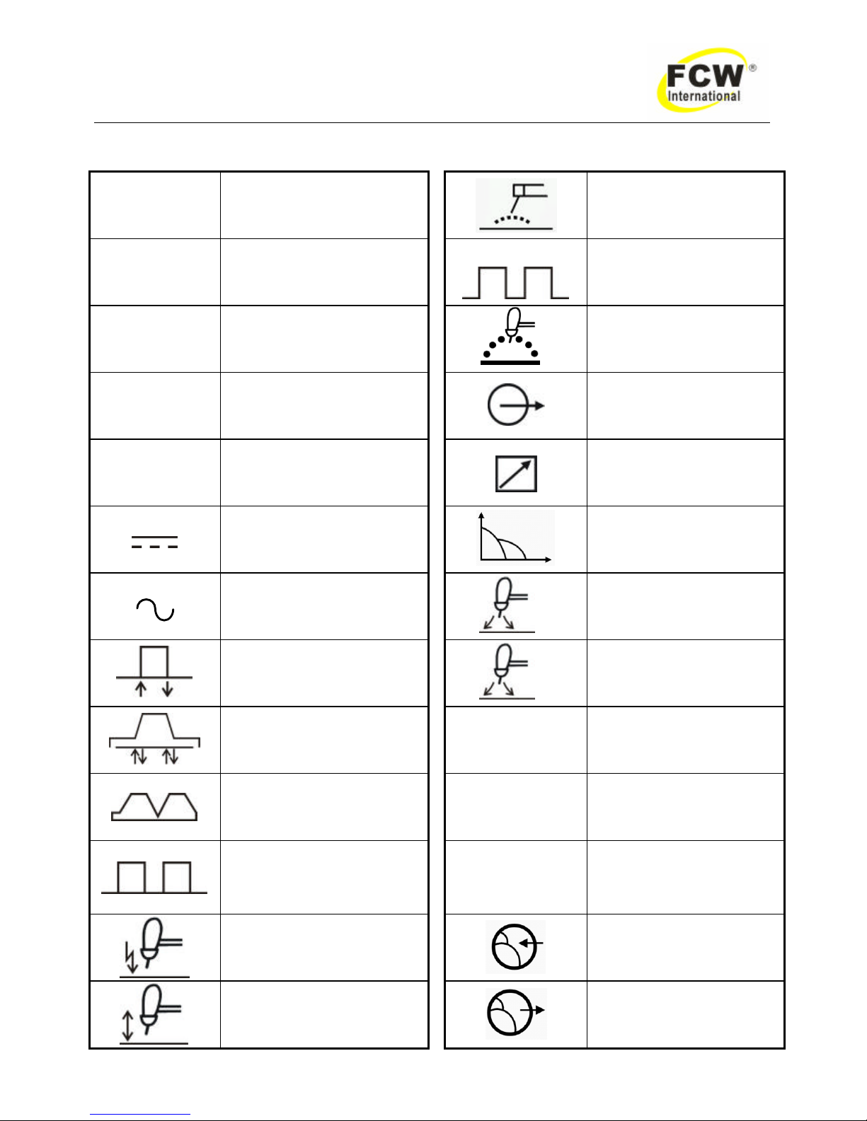
SYMBOL LEGEND
A
Amperage
Stick (SMAW)
V
Voltage
Pulse Current Function
(GTAW)
Hz
Hertz (frequency)
t
Spot Time (GTAW)
SEC
Seconds
Remote outputs control
(Panel/Remote)
%
Percent
Remote Function
DC (Direct Current )
Arc Control (SMAW)
AC (Alternating Current )
t
2
Gas Post-Flow Time
2T (GTAW)
t
1
Gas Pre-Flow Time
4T (GTAW)
VRD
Voltage Reduction
Device Circuit
Repeat Function (GTAW)
—
Negative
Spot Function (GTAW)
+
Positive
High Frequency Starting
(GTAW)
Gas Input
Lift Start (GTAW)
Gas Output
Page 4

- 3 -
DYNA POWER 350CV、503CV、500CV、630CV、630HCV Operating Manual
STATEMENT OF WARRANTY
LIMITED WARRANTY: "FCW" warrants to customers of its authorized distributors hereafter "FCW" that its products will be free
of defects in workmanship or material. Should any failure to conform to this warranty appear within the time period applicable to
the FCW products as stated below, FCW shall, upon notification thereof and substantiation that the product has been stored,
installed, operated, and maintained in accordance with FCW’s specifications, instructions, recommendations and recognized
standard industry practice, and not subject to misuse, repair, neglect, alteration, or accident, correct such defects by suitable
repair or replacement, at FCW ‘s sole option, of any components or parts of the product determined by FCW to be defective.
The FCW COMPANY MAKES NO OTHER WARRANTY, EXPRESS OR IMPLIED. THIS WARRANTY IS EXCLUSIVE AND IN
LIEU OF ALL OTHERS, INCLUDING, BUT NOT LIMIT ED TO ANY WARRANTY OF MERCHANTABILITY OR FITNESS FOR
ANY PARTICULAR PURPOSE.
LIMITATION OF LIABILITY: FCW shall not under any circumstances be liable for special, indirect or consequential damages,
such as, but not limited to, lost profits and business interruption. The remedies of the Purchaser set forth herein are exclusive
and the liabil ity of FCW with respect to any contract, or anything done in connection therewith such as the performance or
breach thereof, or from the manufacture, sale, delivery, resale, or use of any goods covered by or furnished by FCW whether
arising out of contract, negligence, strict tort, or under any warranty, or otherwise, shall not, except as expressly provided herein,
exceed the price of the goods upon which such liability is based. No employee, agent, or representative of FCW is authorized to
change this warranty in any way or grant any other warranty.
PURCHASER'S RIGHTS UNDER THIS WARRANTY ARE VOID IF REPLACEMENT PARTS OR ACCESSORIES ARE USED
WHICH IN FCW’S SOLE JUDGEMENT MAY IMPAIR THE SAFETY OR PERFORMANCE OF ANY FCW PRODUCT.
PURCHASER'S RIGHTS UNDER THIS WARRANTY ARE VOID IF THE PRODUCT IS SOLD TO PURCHASER BY
NON-AUTHORIZED PERSONS.
The warranty is effective for the time stated below beginning on the date that the authorized distributor delivers the products to
the Purchaser. Not with standing the foregoing, in no event shall the warranty period extend more than the time stated plus one
year from the date FCW delivered the product to the authorized distributor.
POWER SUPPLIES POWER SUPPLIES & WIRE FEEDERS
MAIN POWER MAGNETICS (STATIC& ROTATING) 1YEAR
ORIGINAL MAIN POWER RECTIFIER 1YEAR
POWER SWITCHING SEMI-CONDUCTORS & CONTROL PC BOARD 1YEAR
ALL OTHER CIRCUITS AND COMPONENTS INCLUDING 1YEAR
BUT NOT LIMITED TO, CONTACTORS, RELAYS,
SOLENOIDS, PUMPS, SWITCHES, MOTORS
Warranty repairs or replacement claims under this limited warranty must be submitted to FCW by an authorized FCW repair
facility within thirty (30) days of purchaser’s notice of any Warranty Claim. No transportation costs of any kind will be paid under
this warranty. Transportation charges to send products to an authorized warranty repair facility shall be the responsibility of the
Purchaser. All returned goods shall be at the Purchaser’s risk and expense. This warranty supersedes all previous FCW
warranties.
Page 5
- 4 -
DYNA POWER 350CV、503CV、500CV、630CV、630HCV Operating Manual
1.0 GENERAL INFORMATION
1.01 Notes, Cautions and W arnings
Throughout this manual, notes, cautions, and warnings are used to highlight important information. These
highlights are categorized as follows:
NOTE
An operation, procedure, or background information which requires additional emphasis or is helpful in
efficient operation of the system.
CAUTION
A procedure which, if not properly followed, may cause damage to the equipment.
WARNING
A procedure which, if not properly followed, may cause injury to the operator or others in the operating area.
1.02 Important Safety Precautions
WARNING
OPERATION AND MAINTENANCE OF ARC WELDING EQUIPMENT CAN BE DANGEROUS AND
HAZARDOUS TO YOUR HEALTH.
To prevent possible injury, read, understand and follow all warnings, safety precautions and instructions
before using the equipment. Call 86-21-69171135 or your local distributor if you have any questions.
GASES AND FUMES
Gases and fumes produced during the Arc welding or cutting process can be dangerous and hazardous to
your health.
l Keep all fumes and gases from the breathing area. Keep your head out of the welding fume plume.
l Use an air-supplied respirator if ventilation is not adequate to remove all fumes and gases.
l The kinds of fumes and gases from the arc welding/cutting depend on the kind of metal being used,
coatings on the metal, and the different processes. You must be very careful when cutting or welding
any metals which may contain one or more of the following:
Antimony Arsenic Barium Beryllium Cadmium Chromium Cobalt Copper Lead
Manganese Mercury Nickel Selenium Silver Vanadium
l Always read the Material Safety Data Sheets (MSDS) that should be supplied with the material you
are using. The se MSDSs will give you the information regarding the kind and amount of fumes and
gases that may be dangerous to your health.
l Use special equipment, such as water or down draft welding/cutting tables, to capture fumes and
gases.
l Do not use the welding torch in an area where combustible or explosive gases or materials are
located.
l Phosgene, a toxic gas, is generated from the vapors of chlorinated solvents and cleansers. Remove
all sources of these vapors.
Page 6
- 5 -
DYNA POWER 350CV、503CV、500CV、630CV、630HCV Operating Manual
ELECTRIC SHOCK
Electric Shock can injure or kill. The arc welding process uses and produces high voltage electrical energy.
This electric energy can cause severe or fatal shock to the operator or others in the workplace.
l Never touch any parts that are electrically “live” or “hot.”
l Wear dry gloves and clothing. Insulate yourself from the work piece or other parts of the welding
circuit.
l Repair or replace all worn or damaged parts.
l Extra care must be taken when the workplace is moist or damp.
l Install and maintain equipment according to NEC code, refer to relative standards
l Disconnect power source before performing any service or repairs.
l Read and follow all the instructions in the Operating Manual.
FIRE AND EXPLOSION
Fire and explosion can be caused by hot slag, sparks, or the arc weld.
l Be sure there is no combustible or flammable material in the workplace. Any material that cannot be
removed must be protected.
l Ventilate all flammable or explosive vapors from the workplace.
l Do not cut or weld on containers that may have held combustibles.
l Provide a fire watch when working in an area where fire hazards may exist.
l Hydrogen gas may be formed and trapped under aluminum workpieces when they are cut
underwater, or while using a water table. Do not cut aluminum alloys underwater or on a water table
unless the hydrogen gas can be eliminated or dissipated. Trapped hydrogen gas that is ignited will
cause an explosion.
NOISE
Noise can cause permanent hearing loss. Arc welding/cutting processes can cause noise levels to exceed
safe limits. You must protect your ears from loud noise to prevent permanent loss of hearing.
l To protect your hearing from loud noise, wear protective ear plugs and/ or ear muffs. Protect others
in the workplace.
l Noise levels should be measured to be sure the decibels (sound) do not exceed safe levels.
ARC WELDING RAYS
Arc Welding/ Cutting Rays can injure your eyes and burn your skin. The arc welding/cutting process produces
very bright ultra violet and infra red light. These arc rays will damage your eyes and burn your skin if you are
not properly protected.
l To protect your eyes, always wear a welding helmet or shield. Also always wear safety glasses with
side shields, goggles or other protective eye wear.
l Wear welding gloves and suitable clothing to protect your skin from the arc rays and sparks.
l Keep helmet and safety glasses in good condition. Replace lenses when cracked, chipped or dirty.
l Protect others in the work area from the arc rays. Use protective booths, screens or shields.
Page 7
- 6 -
DYNA POWER 350CV、503CV、500CV、630CV、630HCV Operating Manual
1.03 Transporting methods
These units are equipped with a handle for carrying purposes.
WARNING: ELECTRIC SHOCK can kill.
DO NOT TOUCH live electrical parts. Disconnect input power conductors from de-energized supply
line before moving the welding power source.
WARNING: FALLING EQUIPMENT can cause serious personal injury and
equipment damage.
l Lift unit with handle on top of case.
l Use handcart or similar device of adequate capacity.
l If using a fork lift vehicle, place and secure unit on a proper skid before transporting.
Page 8
- 7 -
DYNA POWER 350CV、503CV、500CV、630CV、630HCV Operating Manual
2.0 INSTALLATION RECOMMENDATION
Installation Environment
DYNA POWER is designed for use in hazardous environments.
Examples of environments with increased hazardous environments are -
In locations in which freedom of movement is restricted, so that the operator is forced to perform the work
in a cramped (kneeling, sitting or lying) position with physical contact with conductive parts; In locations which
are fully or partially limited by conductive elements, and in which there is a high risk of unavoidable or
accidental contact by the operator, or in wet or damp hot locations where humidity or perspiration
considerable reduces the skin resistance of the human body and the insulation properties of accessories.
Environments with hazardous environments do not include places where electrically conductive parts in
the near vicinity of the operator, which can cause increased hazard, have been insulated.
Installation Location
Be sure to locate the welder according to the following guidelines:
l In areas, free from moisture and dust.
l In areas, free from oil, steam and corrosive
gases.
l In areas, not exposed to direct sunlight or rain.
l Ambient temperature: between -10 degrees C
to 40 degrees C.
l In areas, not subjected to abnormal vibration or
shock.
l Place at a distance of 304.79mm or more from
walls or similar that could restrict natural airflow
for cooling.
WARNING
FCW advises that this equipment be electrically connected by a qualified electrician.
The following Primary Current recommendations are required to obtain the maximum welding current and
duty cycle from this Power Supply:
Model
Primary
supply lead
size
Minimum primary current
circuit size
Current & Duty Cycle
DYNA POWER 350CV Minimum 6.0mm
2
380V/ 22A
415V/ 20.1A
350A/ 31.5V@60%
320A/ 30V@100%
DYNA POWER 503CV Minimum 8.0mm
2
380V/ 38.5A
415V/ 35.3A
500A/ 39V@40%
450A/ 36.5V@60%
400A/ 34V@100%
DYNA POWER 500CV Minimum 8.0mm
2
380V/ 38.5A
415V/ 35.3A
500A/ 39V@60%
450A/ 36.5V@100%
DYNA POWER 630CV Minimum 10.0mm
2
380V/ 62.5A
415V/ 57.2A
630A/ 44V@60%
500A/ 39V@100%
DYNA POWER 630HCV Minimum 10.0mm
2
380V/ 62.5A
415V/ 57.2A
630A/ 44V@100%
Table 1 primary current circuit sizes to achieve maximum current
Page 9
- 8 -
DYNA POWER 350CV、503CV、500CV、630CV、630HCV Operating Manual
2.01 Electrical Input Connections
WARNING: ELECTRIC SHOCK can kill; SIGNIFICANT DC VOLTAGE is
present after removal of input power.
DO NOT TOUCH live electrical parts
SHUT DOWN welding power source, disconnect input power employing lockout/ tagging procedures.
Lockout/ tagging procedures consist of padlocking line disconnect switch in open position, removing fuses
from fuse box, or shutting off and red-tagging circuit breaker or other disconnecting device.
Electrical Input Requirements
Operate the welding power source from three phases 50/ 60 Hz, AC power supply. The input voltage must
match one of the electrical input voltages shown on the input data label on the unit nameplate. Contact the
local electric utility for information about the type of electrical service available, how proper connections
should be made, and inspection required.
The line disconnect switch provides a safe and convenient means to completely remove all electrical power
from the welding power supply whenever necessary to inspect or service the unit.
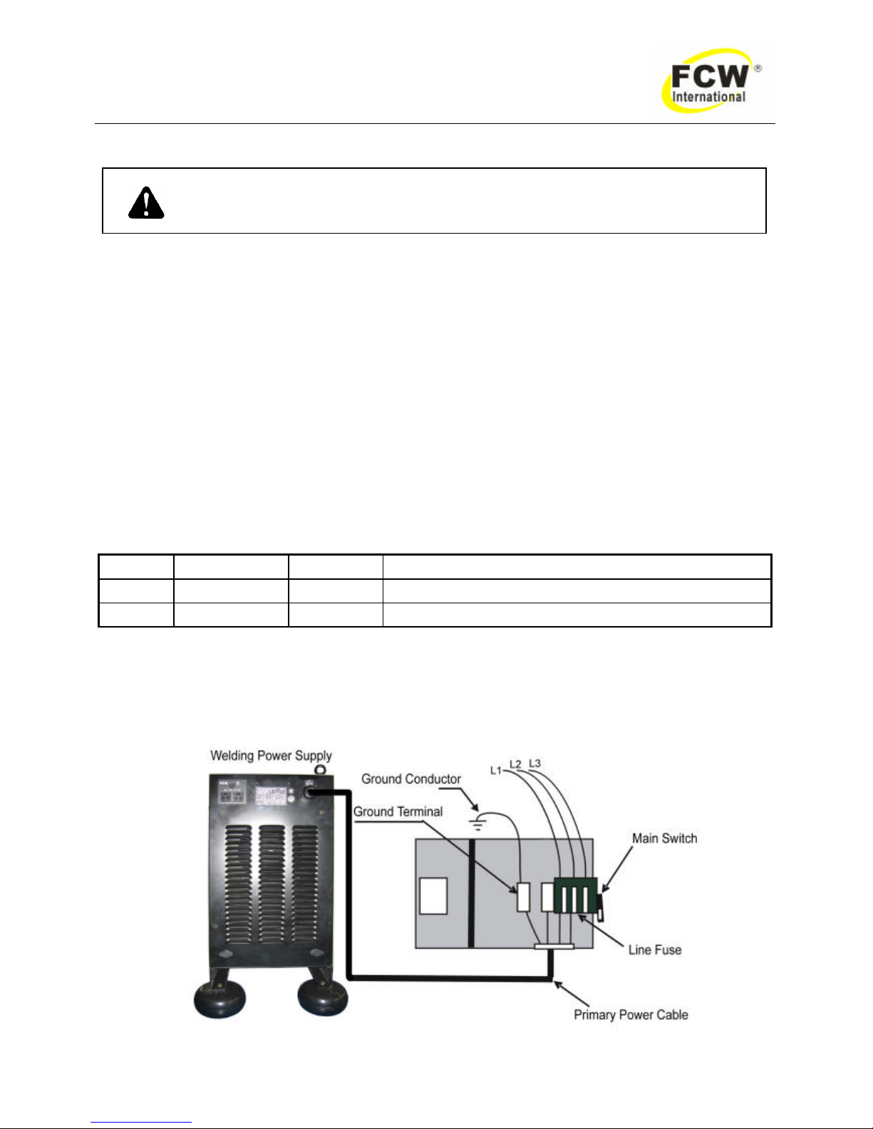
According to Table 1 and below as a guide to select line fuses for the disconnect switch.
Phase Input Voltage Fuse Size Model
3 phases
380/415V AC 60 Amps POWER 350CV
3 phases
380/415V AC 100 Amps POWER 503CV、500CV、630CV、630HCV
Table 2
Notice: Fuse size is based on not more than 200 percent of the rated input amperage of the
welding power source (Based on Article 630, National Electrical Code).
Figure 1 Electrical input connections
Page 10
- 9 -
DYNA POWER 350CV、503CV、500CV、630CV、630HCV Operating Manual
2.02 Specifications
MODEL
POWER
350CV
POWER
503CV
POWER
500CV
POWER
630CV
POWER
630HCV
Input voltage and
frequency and
phases
380/415V 3ph 380/415V 3ph 380/415V 3ph 380/415V 3ph 380/415V 3ph
KVA @ max output
14.5KW
25.3KW
25.3KW 41KW 41KW
Max current
350A
500A
500A 630A 630A
Output current range
30~350A
30~500A
30~500A 30~630A 30~630A
Open circuit voltage
78/85V
78/85V
78/85V 78/85V 78/85V
Duty cycle at 40℃
60%
40%
60% 60% 100%
Weight
52.5Kg
55Kg
70Kg 85Kg 85Kg
Dimensions
550×300×490 550×300×490 560×365×640 560×365×640 560×365×880
Table 3
2.03 Duty cycle
The duty cycle of a welding power source is the percentage of a ten (10) minute period that it can be
operated at a given output without causing overheating and damage to the unit. If the welding amperes
decrease, the duty cycle increases. If the welding amperes are increased beyond the rated output, the duty
cycle will decrease.
WARNING: Exceeding the duty cycle ratings will cause the thermal overload
protection circuit to become energized and shut down the output until has
cooled to normal operating temperature
Continually exceeding the duty cycle ratings
can cause damage to the welding power source.
NOTICE:
Due to variations that can occur in manufacture products, claimed performance, voltages, ratings, all
capacities, measurements, dimensions and weights quoted are approximate only. Achievable capacities and
ratings in use and operation will depend upon correct installation, use, applications, maintenance and
service.
Page 11
- 10 -
DYNA POWER 350CV、503CV、500CV、630CV、630HCV Operating Manual
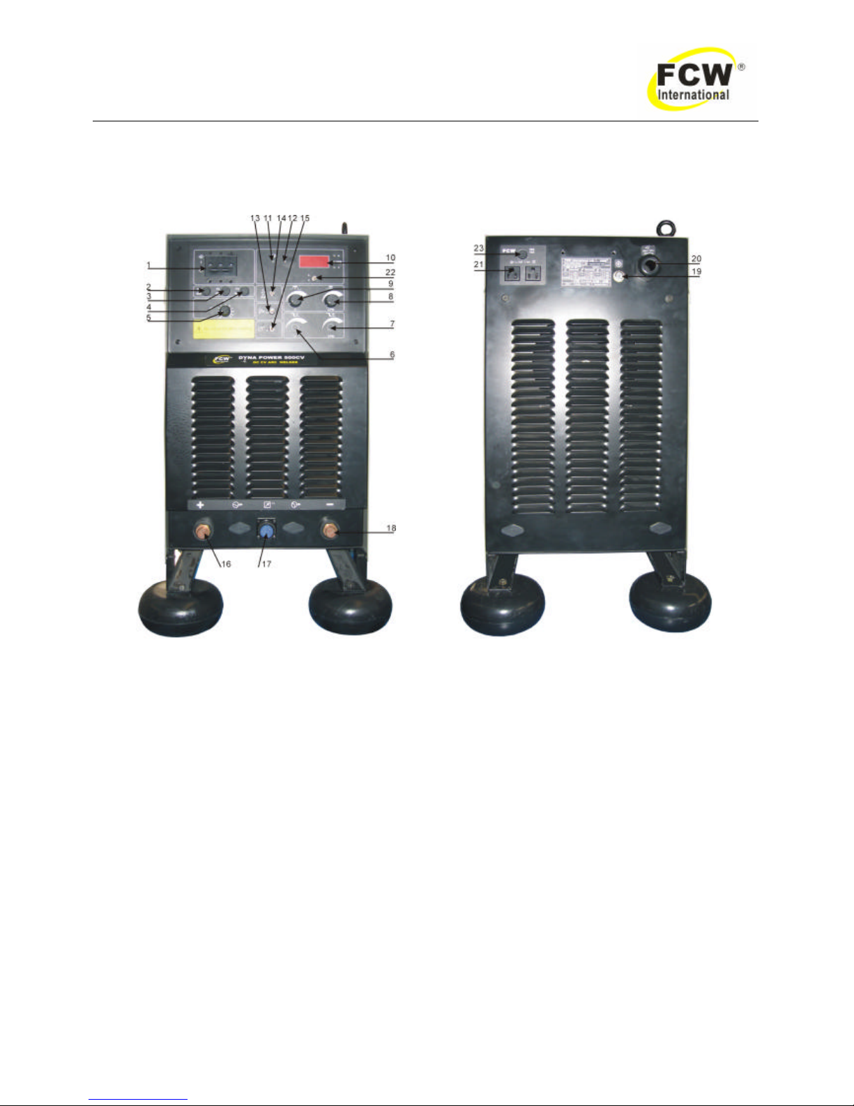
3.0 OPERATOR CONTROLS
3.01 DYNA POWER controls
Figure 2
1. Main Circuit Bleaker— Switching to the ON position energizes the welding power source.
2. Fuse 8A
3. Fuse 2A
4. Fuse 2A
5. Inductance Control (GMAW)
6. Down Slope Voltage Control (Options)
7. Down Slope Wire Feed Speed Control (Options)
8. Wire Feed Speed Control
9. Voltage Control/ Amperage Control
10. Digital Meter
11. AC Power Indicator— Lights when in the ON position.
12. Warning Indicator— Activates under the following conditions:
• Input voltage is too low/ too high
• Thermal overload
13. Gas Switch— Switching to the ON position activate the gas.
14. Control Switch— 2T/4T.
15. Remote Control Switch— Switching to the ON position remote control start.
Page 12
- 11 -
DYNA POWER 350CV、503CV、500CV、630CV、630HCV Operating Manual
16. Positive Terminal— 95mm Screw receptacle (for wire feeder).
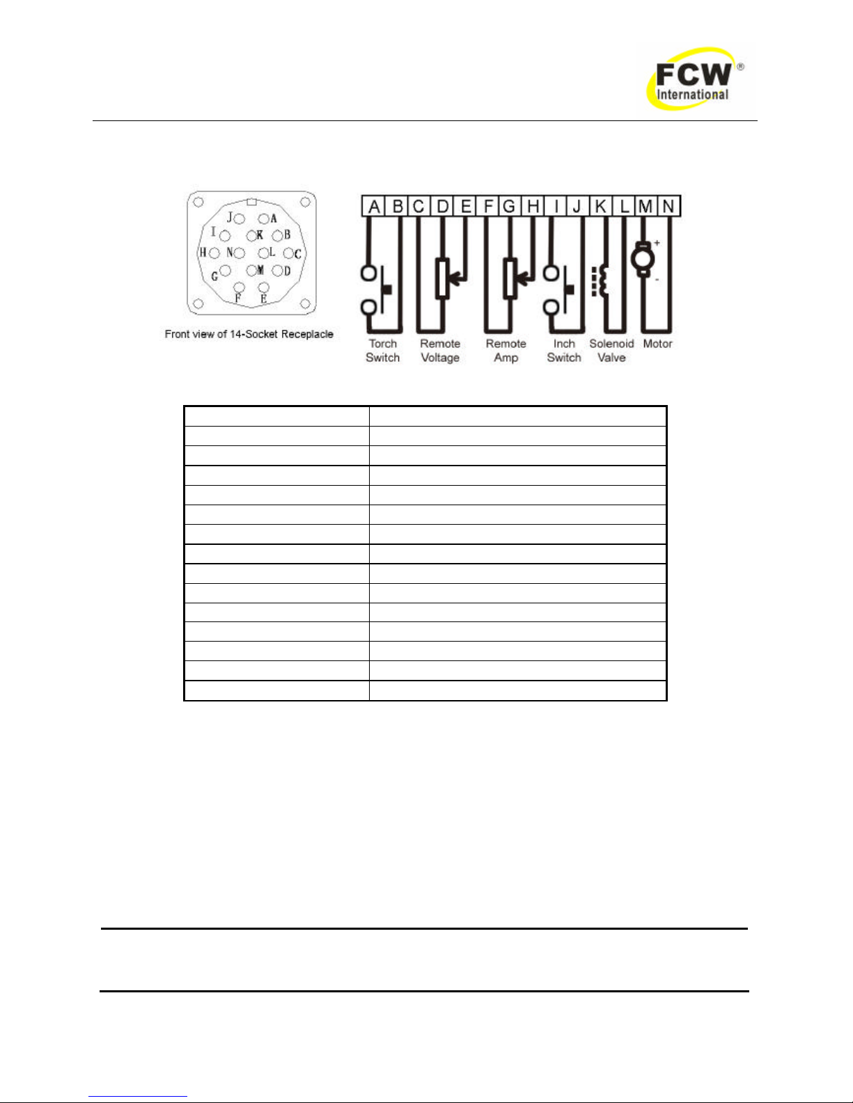
17. 14-Pin Receptacle— U sed to connect the wire feeder.
Figure 3
Pin Function
A Torch switch
B Torch switch
C Remote voltage
D Remote voltage
E Remote voltage
F Remote amp
G Remote amp
H Remote amp
I Inch switch
J Inch switch
K Solenoid valve
L Solenoid valve
M Motor
N Motor
Table 4
18. Negative Terminal— 95mm Screw receptacle (for work cable).
19. Ground Screw— Ground cable.
20. Input Power Cable Port
21. 110VAC Auxiliary Power (Options)
22. Meter Selection
23. Fuse
WARNING
When the welder is connected to the p rimary supply voltage, the internal electrical
components maybe at primary potential with respect to earth.
Page 13
- 12 -
DYNA POWER 350CV、503CV、500CV、630CV、630HCV Operating Manual
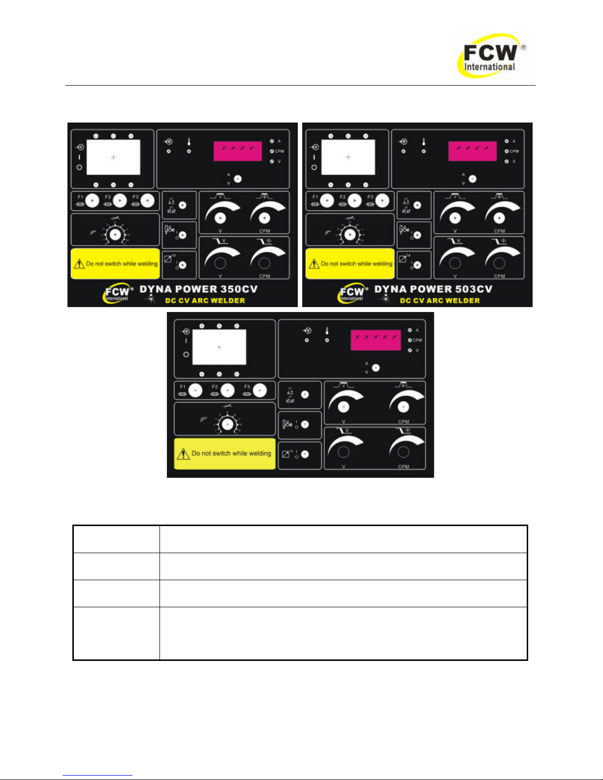
3.02 Weld parameters description
(DYNA POWER 500CV、630CV、630HCV front panel)
Figure 4 DYNA POWER series front panel with parameter description
Parameter Description
Welding Voltage This parameter sets the welding voltage.
Inductor
This parameter sets the electrode inductor.
Burnback
MIG only. Burnback time is the difference between the wire feed motor stopping and
switching off of the welding current. The Burnback allows the electrode wire to burn
out of the molten metal weld pool, to separate the electrode wire from work piece.
Table 5 Weld parameter description for DYNA POWER series
Page 14
- 13 -
DYNA POWER 350CV、503CV、500CV、630CV、630HCV Operating Manual
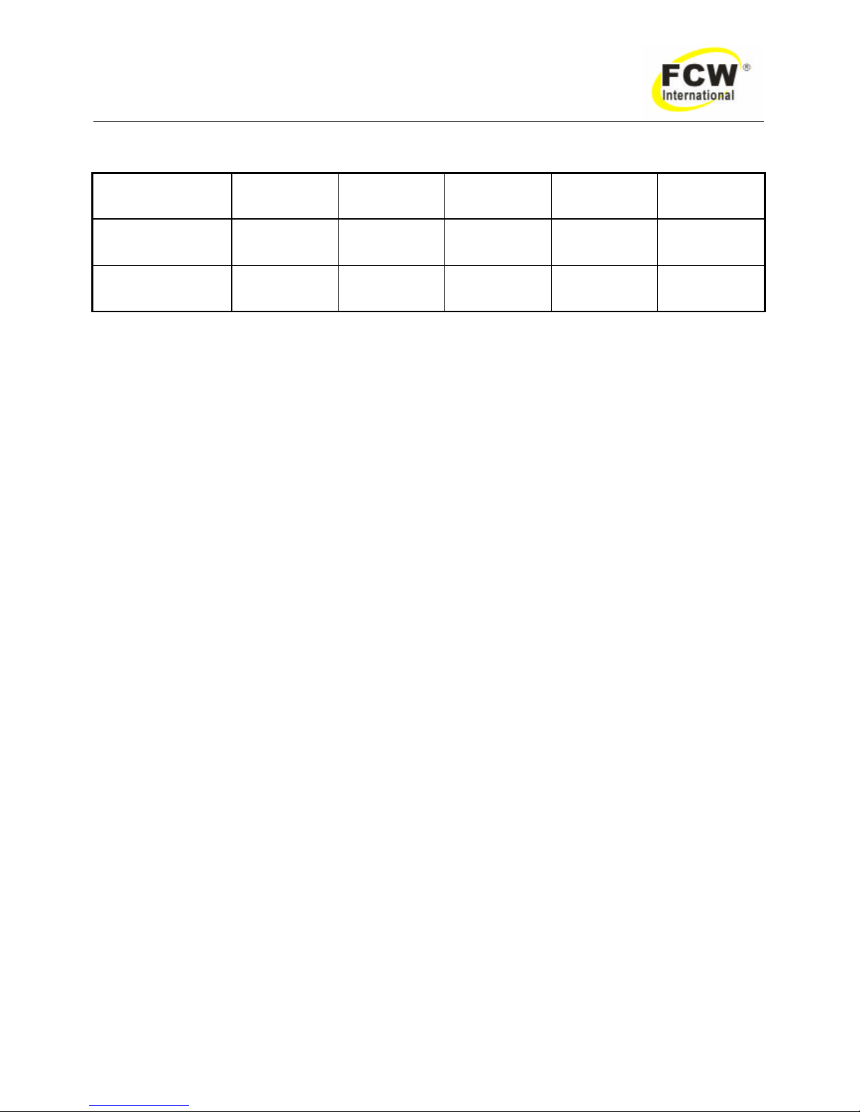
3.03 Weld parameter for DYNA POWER series
Model
POWER
350CV
POWER
503CV
POWER
500CV
POWER
630CV
POWER
630HCV
PEAK CURRENT 350A 500A 500A 630A 630A
WELD VOLTAGE 15.5~31.5V 15.5~39V 15.5~39V 15.5~44V 15.5~44V
Table 6 Weld parameters for DYNA POWER series
Page 15
- 14 -
DYNA POWER 350CV、503CV、500CV、630CV、630HCV Operating Manual
4.0 SET-UP FOR MIG/MAG
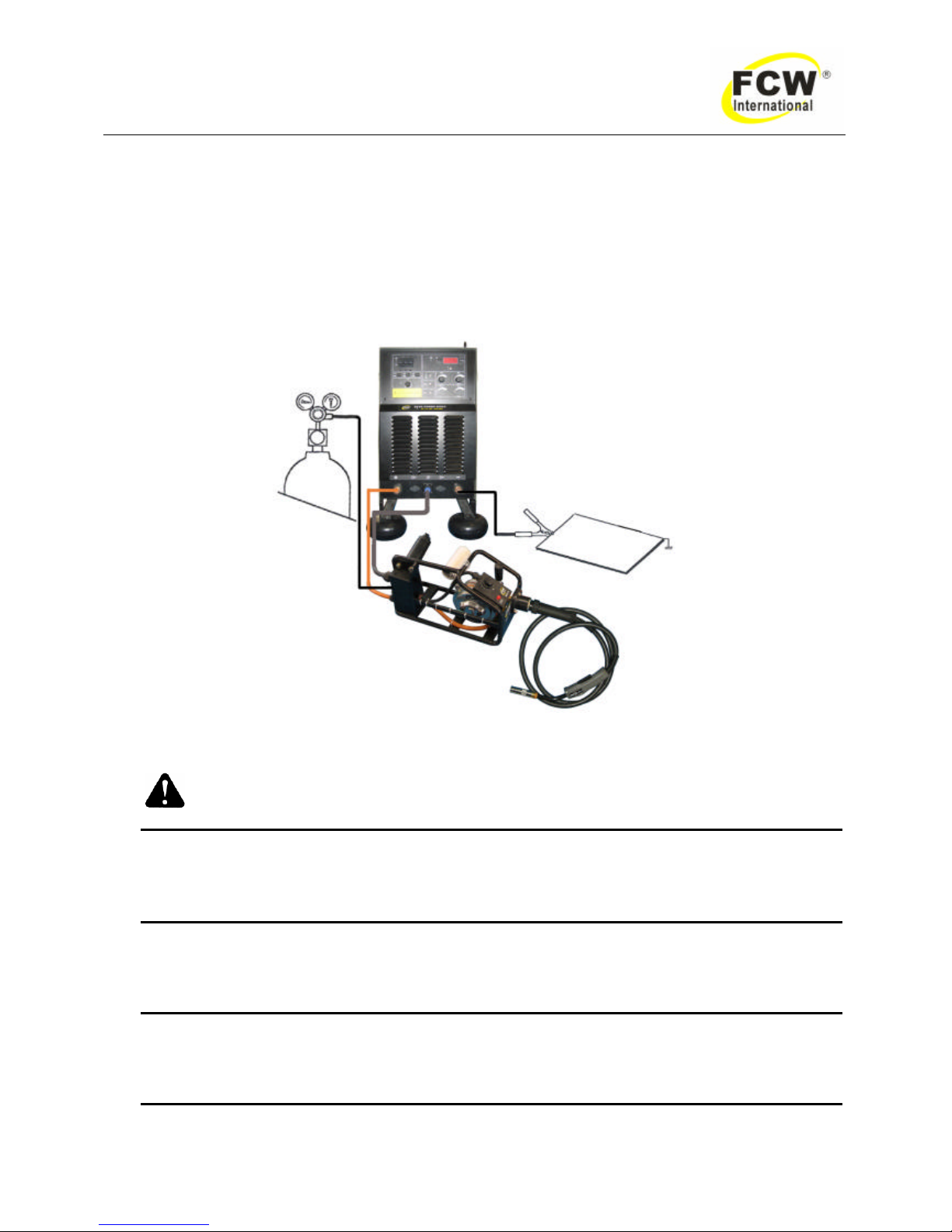
Conventional operating procedures apply when using the w elding power source, i.e. connect work lead
directly to work piece and welding cable is used to electrode holder. Wide safety margins provided by the coil
design ensure that the w elding power source will withstand short-term overload without adverse effects. The
welding current range values should be used as a guide only. Current delivered to the arc is dependent on the
welding arc voltage, and as welding arc voltage varies between different classes of electrodes, welding
current at any one setting would vary according to the type of electrode in use. The operator should use the
welding current range va lues as a guide, and then finally adjust the current setting to suit the application.
Figure 5 Set up for DYNA POWER Series
WARNING:
Before connecting the work clamp to the work and inserting the electrode in the electrode holder
make sure the Primary power supply is switched off.
CAUTION 2:
Remove any packaging material prior to use. Do not block the air vents at the front or rear of the
Welding Power Source.
Page 16
- 15 -
DYNA POWER 350CV、503CV、500CV、630CV、630HCV Operating Manual
5.0 POWER SUPPLY CONTROLS INDICATORS AND REATURES
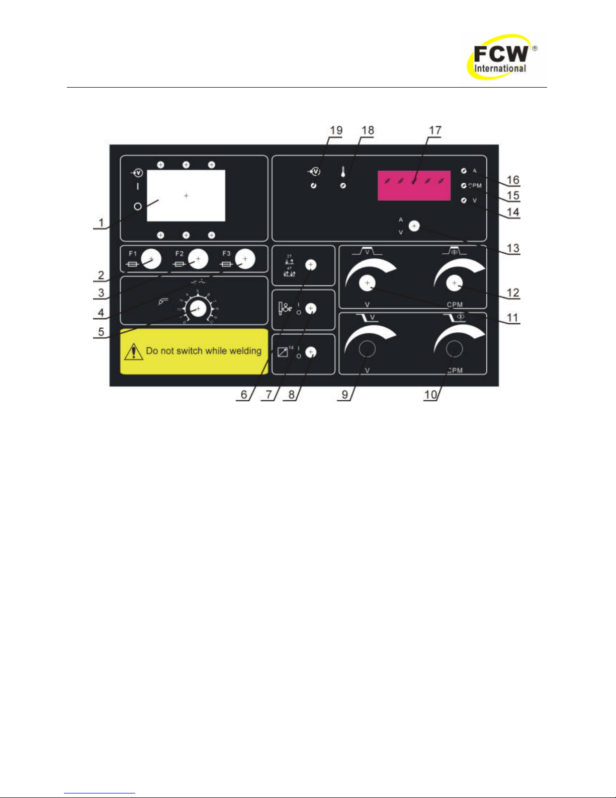
Figure 6 DYNA POWER series front panel
1. Main Circuit Bleaker— Switching to the ON position energizes the welding power source.
2. Fuse 8A
3. Fuse 2A
4. Fuse 2A
5. Inductance Control (GMAW)
6. Control Switch— 2T/4T.
7. Gas Swi tch— Switching to the ON position activate the gas.
8. Remote Control Switch— Switching to the ON position remote control start.
9. Down Slope Voltage Control
10. Down Slope Wire Feed Speed Control
11. Voltage Control/ Amperage Control
12. Wire Feed Speed Control
13. Amp/ Voltage Digital display switch.
14. Volt Indicator— Voltage.
15. CPM Indicator— Wire feed speed.
16. Amp Indicator— Current.
17. Digital Meter
18. Warning Indicator— Activates under the following conditions:
19. AC Power Indicator— Lights when in the ON position.
Page 17
- 16 -
DYNA POWER 350CV、503CV、500CV、630CV、630HCV Operating Manual
5.01 Basic MIG Welding Guide
The welding power supply has two control settings that have to balance. These are the wire speed
control and the voltage control switches. The welding current is determined by the wire speed control, the
current will increase with increased wire speed, resulting in a shorter arc. Less wire speed will reduce the
current and lengthen the arc. By decreasing the voltage, a shorter arc is obtained with little change in welding
current, because the wire speed is not changed.
l When changing to a different electrode wire diameter, different control settings are required. A thinner
electrode wire needs more w ire speed to achieve the same current level.
l A satisfactory weld cannot be obtained if the w ire speed and voltage switch settings are not adjusted to
suit the electrode wire diameter and dimensions of the work piece.
l If the w ire speed is too high for the welding voltage, “stubbing” will occur as the wire dips into the molten
pool. If the w ire speed is too slow for the welding voltage, large drops will form on the end of the
electrode wire, causing spatter. Suppose that wire speed is constant, if the welding voltage is too high,
large drops will form on the end of the electrode wire, causing spatter; if the voltage is too low, the wire
will not melt.
5.02 Position of MIG Gun
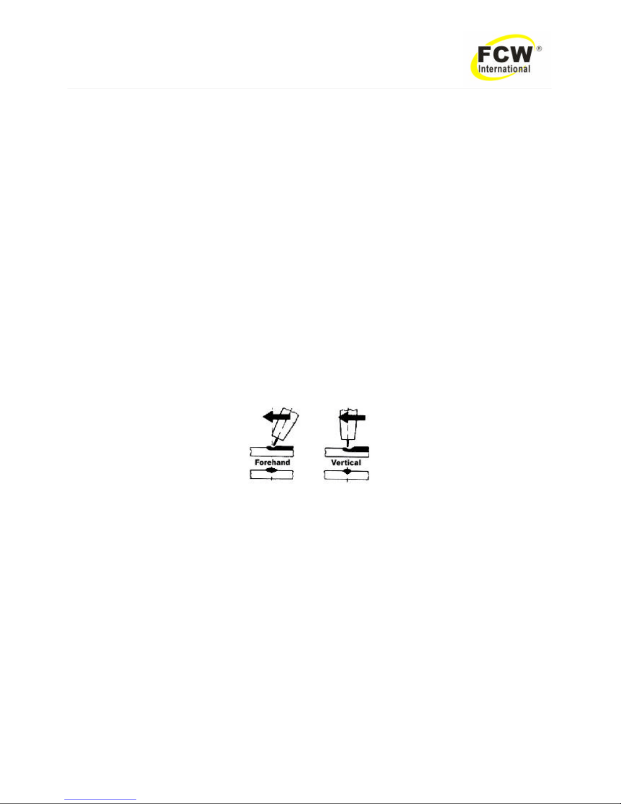
The angle of MIG gun to the weld has an effect on the width of the weld run.
Figure 7 MIG gun angle
5.03 Distance from the MIG Gun Nozzle to the Work Piece
The electrode stick out from the MIG gun nozzle should be between 2.0mm to 5.0mm. This distance may
vary depending on the type of joint that is being weld.
5.04 Travel Speed
S peed at which a weld travels influences the width of the weld and penetration of the welding run.
5.05 Electrode Wire Size Selection
The choice of electrode wire size in conjunction with shielding gas used depends on:
Page 18
- 17 -
DYNA POWER 350CV、503CV、500CV、630CV、630HCV Operating Manual
l Thickness of the metal to be welded.
l Type of joint.
l Capacity of the wire feed unit and power supply.
l The amount of penetration required.
l The deposition rate required.
l The bead pro file desired
l The position of welding and cost of the electrode wire.
Weld metal deposition rate is proportional to current density. Current density is defined as the current per
cross sectional area of electrode wire and is normally expressed as amps per mm2. An example is tabled
below.
Electrode Wire Size
Current (A ) Current Density (A/mm2) Deposition Rate (lbs/hour)
0.9mm (.035”) 200 314 7.0
1.2mm (.045”) 200 177 6.2
Table 7 0.9mm/ 1.2mm wire deposition rate
This demonstrates that where the upper limit of current is limited by the machine capacity and duty cycle,
higher deposition rates therefore greater productivity will be achieved by using smaller electrode wire. The
DYNA MIG series is a particularity efficient MIG welder with the 0.9mm~1.2mm steel wire in spray transfer
mode. 0.9mm wire cost approx. 10% more than 1.2mm but is deposited approx 15% faster.
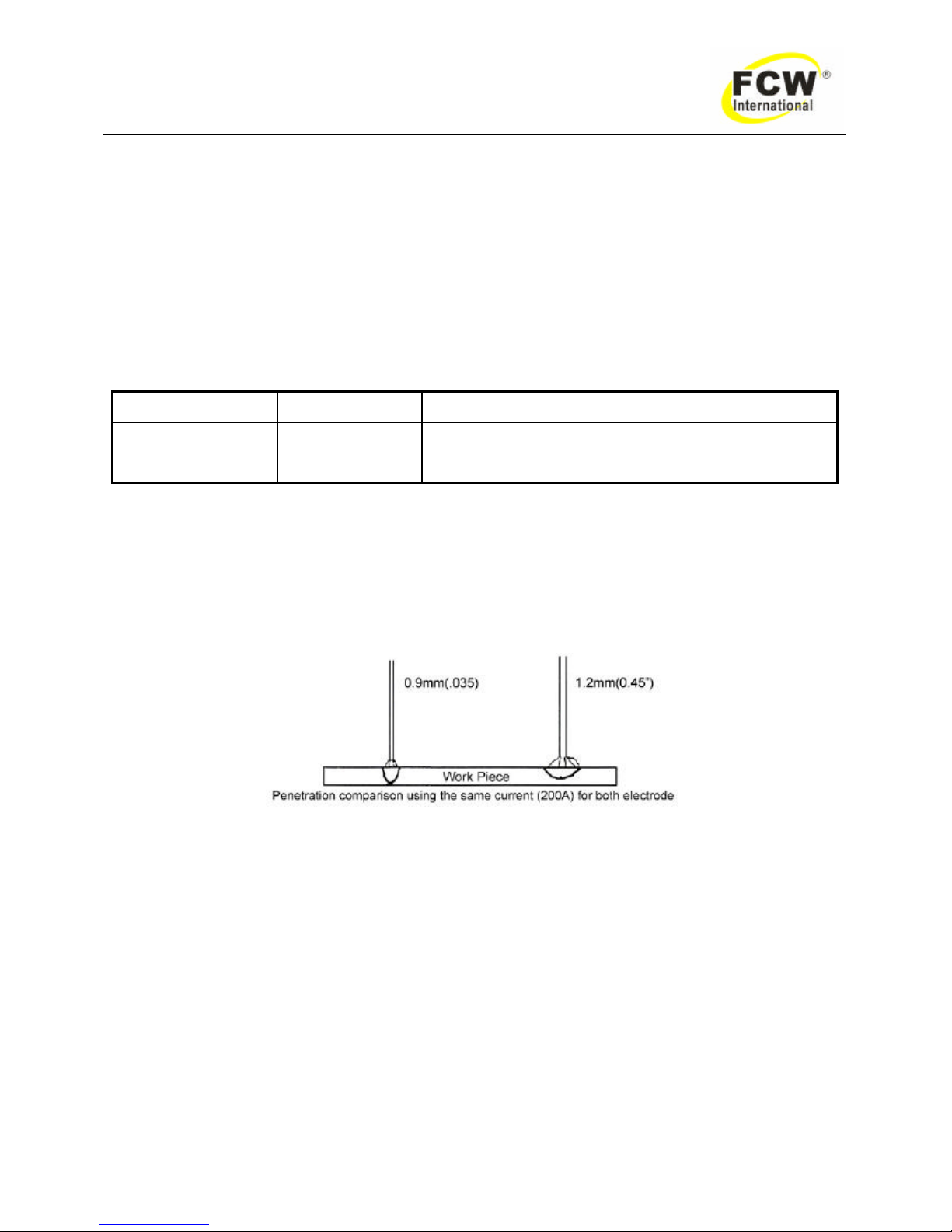
H igh current density or smaller diameter wire also gives deeper penetration as shown:
Figure 8 Wire penetration comparison
5.06 Spot Welding Operation
Fit a spot welding nozzle to the MIG gun for consistent spot welding operations. The DYNA MIG power
supply will operate effectively using 0.8~1.2mm electrode wire when spot welding. Penetration depth is
limited when using 0.6mm electrode wire for spot welding. Set the controls as follows for spot welding:
1. Coarse & fine voltage selector switches and w ire speed control.
Select higher voltage selector switch positions and set the wire speed control between 354 to 590ipm
(9~15 meters/ minute)
2. Mode selector switch.
3. Spot Time .
4. Burnback Time .
Page 19
- 18 -
DYNA POWER 350CV、503CV、500CV、630CV、630HCV Operating Manual
6.0 MAINTENANCE
If this equipment does not operate properly, stop work immediately and investigate the cause of the
malfunction. Maintenance work must be performed by an experienced, qualified person only. Any electrical
work must be performed by an electrician or other person properly trained in servicing electrical equipment.
Do not permit untrained persons to inspect, clean or repair this equipment. Use only recommended
replacement parts when servicing this machine.
Periodically clean the inside of the welding power source by using clean dry compressed air of not over
25psi as normal preventive maintenance. At the time of the cleaning, a full inspection of the welding machine
and setup should be performed. Ch eck warning labels on the machine for readability; replace if necessary.
Check input and output connections as well as frame ground connections to the machine to insure that they
are tight and the wires are not frayed or overheated. Inspect internal wiring of machine for loose or frayed
connections; tighten or repair as necessary. It would also be advisable to check connections to wire feeders,
fixtures, etc., at this time. Any damaged cable or hoses should be replaced.
DANGER: HIGH VOLTAGE is present inte rnally even with the control power switch in the
OFF position. Before inspecting, cleaning, or servicing, disconnect and lock out input power to
the power source.
7.0 BASIC TROUBLESHOOTING
WARNING
There are extremely dangerous voltages and power levels present inside this product.
Do not attempt to open or repair unless you are an accredited FCW service agent and
you have had training in power measurements and troubleshooting techniques.
If major complex subassemblies are faulty, then the w elding power source must be returned to an
accredited FCW service agent for repair.
The basic level of troubleshooting is that which can be performed without special equipment or
knowledge.
7.01 Check the item and excrescent phenomenon exclusion method
Page 20
- 19 -
DYNA POWER 350CV、503CV、500CV、630CV、630HCV Operating Manual
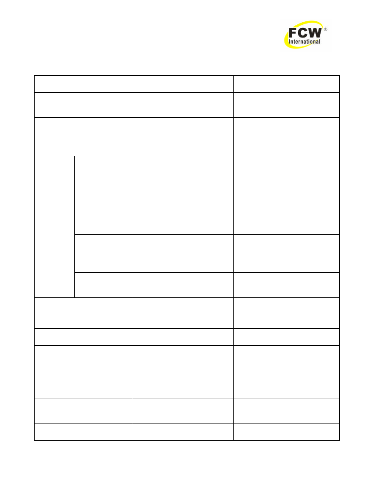
Troubleshooting Guide
Fault Cause Remedy
1. The AC power indicator ligh t is
not lit and welding arc can not
be established.
1. No power input or main power
switches damage.
2. Indicator damage.
1. Check input power or replace
main power switch.
2. Replace indicator light.
2. The AC power indicator light on
and welding arc can not be
established.
1. Input voltage unstable.
2. Diode damage.
1. Connect stabilizer or reset power
switch.
2. Replace diode.
3. The warning indicator light on. Over load. Reduce current or wait moment.
a. No gas flow
N o wire feed
N o output
1. MIG torch plug is not insert into
the socket or the connect is
bad.
2. MIG torch damage (diagnose
method: make the welding
machine control socket two
pins short circuit, the faulty
disappear).
3. Wire feeder plug is not insert
into the socket or the connect
condition is bad.
1. Insert the plug correctly, and
rotate it clockwise.
2. Repair or replace MIG torch.
3. Insert the plug correctly, and
rotate it clockwise.
b. N o gas flow
H ave wire feed
H ave output
1. The gas line is not turn on.
2. The MIG torch damage.
3. The solenoid damage.
4. Wire speed Control board
damage.
1. Turn on the gas system.
2. Repair or replace.
3. Repair or replace.
4. Repair or replace.
4. Turn on
torch
control
switch
c. H ave gas flow
H ave wire feed
N o output
1. Disconnect the work piece to
the work ground cable.
2. Main Board damage.
1. Reconnect the ground cable and
tighten the work piece.
2. Repair or replace.
5. Faulty welding arc control.
1. The MIG torch damage.
2. Faulty setting .
3. Main board damage.
1. Repair or replace the MIG torch.
2. Read this manual carefully and
set up correctly.
3. Repair or replace.
6. The arc weld has no output.
1. Transformer bad connect.
2. AC contactor bad connect.
1. Repair or replace.
2. Repair or replace.
7. Arc start difficult or often break
off.
1. The power supply voltage is too
low or the cable is too thin.
2. Main board damage.
3. The contact tip damage.
4. The work piece bad connect.
5. The wire roller damage.
6. The torch lead damage.
1. Connect a stabilizer or increase
the thickness of the power cable.
2. Repair or replace.
3. Repair or replace.
4. Repair or replace.
5. Replace
6. Replace
8. The maximum output welding
current can not achieved in the
rated input voltage.
Main board damage. Repair or replace.
9. The current decrease in the
weld process.
Faulty cable connected to work
piece.
Make sure the cable positive connect
to the work piece correctly.
Page 21
- 20 -
DYNA POWER 350CV、503CV、500CV、630CV、630HCV Operating Manual
10. TIG mode unstable Arc.
1. Wrong tungsten electrode.
2. TIG torch bad contact or
damage.
3. Argon flow control is improper,
not pure argon gas.
4. TIG torch gas hose is cut.
5. TIG torch wrong position
(negative for TIG torch).
6. Control PCB damage.
1. Choose right tungsten.
2. Replace TIG torch.
3. Replace argon gas capacity.
4. Replace TIG torch.
5. Reconnect.
6. Replace control PCB.
11.The arc weld has no output
1. The function switch set
incorrectly.
2. Three phase commutate bridge
damage.
3. IGBT damage.
4. Drive board damage.
1. Correctly set the function switch.
2. Replace.
3. Replace.
4. Repair or replace.
12. Arc start difficult or often break
off in arc welding.
1. The weld current setting too
low.
2. The power supply voltage is too
low or the cable is too thin.
3. Control Board damage.
1. Increase.
2. Replace.
3. Replace.
13. Can not display the amperage
or voltage or faulty display.
Display Board damage. Repair or replace.
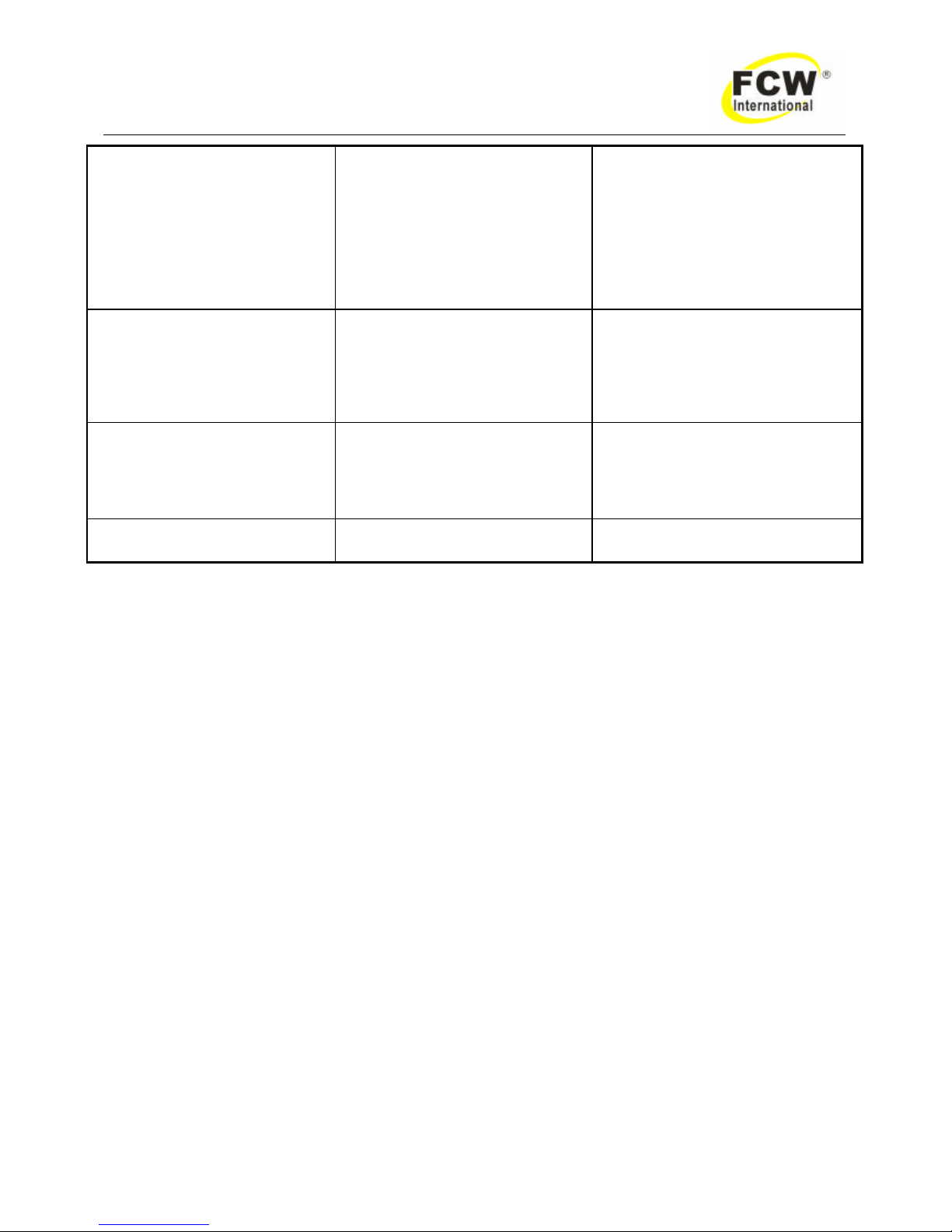
Table 8
7.02 Solving Problems Beyond the Welding Terminals
The general approach to fix gas metal arc welding (GMAW) problems is to start at the wire spool then
work through to the MIG gun. There are two main areas where problems occur with GMAW:
a) Porosity
When there is a gas problem the result is usually porosity within the weld metal. Porosity always stems
from some contaminant within the molten weld pool which is in the process of escaping during solidification of
the molten metal.
Contaminants range from no gas around the welding arc to dirt on the work piece surface.
Porosity can be reduced by checking the following points:
l Gas cylinder contents and flo w meter
Ensure that the gas cylinder is not empty and the flow meter is correctly adjusted to 15 liters per
minute (0.5 cubic feet per minute)
l Gas leaks
Check for gas leaks between the regulator/ cylinder connection and in the gas hose to the power
supply.
l Internal gas hose in the power supply
Ensure the hose from the solenoid valve to the MIG gun adaptor has not fractured and that it is
connected to the MIG gun adaptor.
l Welding in a windy environment
Shield the weld area from the wind or increase the gas flow.
Page 22
- 21 -
DYNA POWER 350CV、503CV、500CV、630CV、630HCV Operating Manual
l Welding dirty, oily, painted oxidized or greasy plate.
Clean contaminates off plate.
l Distance between the MIG gun
Keep the distance between the MIG gun nozzle and the work piece to a minimum. Refer to distance
from the MIG gun nozzle to the w ork piece in 5.03.
l Maintain the MIG gun in good work order
Ensure that the gas holes are not blocked and gas is exiting out of the gun nozzle. Refer to the
WARNING.
Do not restrict gas flow by allowing spatter to build up inside the MIG gun nozzle.
Check that the MIG gun O-rings are not damaged.
WARNING: Disengage the drive roll when testing for gas flow by ear.
b) Inconsistent wire feed
Wire feeding problems can be reduced by checking the following points:
l Wire spool brake is too tight
Feed roller driven by motor in the cabinet will slip.
l Wire spool brake is too loose
Wire spool can unwind and tangle.
l Worn or incorrect feed roller size
U se “U” groove drive feeder roller matched to the aluminum wire size you are welding.
U se “V’” groove drive feeder roller matched to the steel wire size you are welding.
U se “knurled V”’ groove drive feeder roller matched to the flux cored wire size you are welding.
l Mis-alignment of inlet/ outlet guides
Wire will rub against the mis-aligned guides and reduces wire feed ability.
l Liner blocked with debris
Debris is produced by the wire passing through the feed roller, if excessive pressure is applied to
the pressure roller adjuster.
Debris can also be produced by the wire passing through an incorrect feed roller groove shape or
size.
Debris is fed into the liner where it accumulates thus reducing wire feed ability.
l Incorrect or worn contact tip
The contact tip transfers the weld current to the electrode wire. If the hole in the contact tip is too
large then arcing may occur inside the contact tip resulting in the electrode wire jamming in the
contact tip.
When using soft electrode wire such as aluminum it may become jammed in the contact tip due to
expansion of the wire when heated. A contact tip designed for soft electrode wires should be used.
l Poor work lead contact to work piece
If the work lead has a poor electrical contact to the work piece then the connection point will heat up
and result in a reduction of power at the arc.
l Bent liner
This will cause friction between the wire and the liner thus reducing wire feed ability.
Page 23
- 22 -
DYNA POWER 350CV、503CV、500CV、630CV、630HCV Operating Manual
7.03 Weld Problems
Fault Cause Remedy
1. Undercut
A Welding arc voltage too high .
B Incorrect gun angle.
C Excessive heat input.
A Reduce voltage by reducing the voltage
selection switches position or increase the
wire feed speed.
B Adjust angle.
C Increase the gun travel speed and/ or
reduce welding current by reducing the
voltage selection switches position or
reducing the wire feed speed.
2. Lack of penetration
A Welding current too low.
B Joint preparation too narrow
or gap too tight.
C Shielding gas incorrect.
A Increase welding current by increasing
wire feed speed and increasing voltage
selection switch position.
B Increase the joint angle or gap.
C Change to a gas which gives higher
penetration.
3. Lack of fusion Voltage too low.
Increase voltage by increasing voltage
selection switch position.
4. Excessive spatter
A V oltage too high.
B V oltage too low.
A Lower voltage by increasing wire speed
control or reducing the voltage selection
switches.
B Raise voltage by reducing wire speed
control or increasing the voltage selection
switches.
5. Irregular weld shape
A Incorrect voltage and current
settings.
Convex, voltage too low.
Concave, voltage too high.
B Wire is wandering.
C Incorrect shielding gas.
D Insufficient or excessive heat
input.
A Adjust voltage and current by adjusting
the voltage selection switches and the
wire speed control.
B Replace the contact tip.
C Check shielding gas.
D Adjust the wire speed control or voltage
selection switches.
6. Welding cracking
A Weld beads too small.
B Weld penetration narrow and
deep.
C Excessive weld stress.
D Excessive voltage.
E Cooling rate too fast.
A Decrease the travel speed.
B Reduce current and voltage and increase
MIG gun travel speed or select a lower
penetration shielding gas.
C Increase weld metal strength or revise
design.
D Decrease the voltage by reducing the
voltage selection switches.
E Slow the cooling rate by preheating part to
be weld or cool slowly.
7. Cold weld puddle
A Faulty rectifier unit.
B Loose welding cable
connection.
C Low primary voltage.
A H ave an accredited FCW service agent to
test then replace the faulty component.
B Check all welding cable connections.
C Contact supply authority.
Table 9
Page 24
- 23 -
DYNA POWER 350CV、503CV、500CV、630CV、630HCV Operating Manual
7.04 Power Supply Problems
Fault Cause Remedy
1. Input power supply
voltage is ON. Indicator
light is not lit and welding
arc can not be
established.
A Primary fuse is blown .
B Broken connection in primary
circuit.
A Replace Primary fuse.
B H ave an accredited FCW service
agent check primary circuit.
2. Input power indicator
light is not lit and welding
arc can not be
established.
Indicator light is open circuit.
H ave an accredited FCW service agent
replace indicator light.
3. Input power supply is ON
and indicator light is lit
but when the gun trigger
switch is depressed
nothing happens.
Gun trigger switch leads are
disconnected.
Reconnect.
4. Input power supply
voltage is ON, no wire
feed but gas flows from
the MIG gun when the
gun trigger switch is
depressed.
A Electrode wire stuck in conduit
liner or contact up (burn-back
jam).
B Faulty control PCB.
A Check for clogged/ kinked MIG gun
conduit or worn contact tip, replace
faulty components.
B H ave an accredited FCW service
agent investigate the faulty.
5. Wire feeds when the gun
trigger switch is
depressed but arc can
not be established.
Poor or no work lead connection.
Clean work clamp area and ensure good
electrical contact.
6. Wire continues to feed
when the gun trigger
switch is released.
The mode selector switch has
been set to 4T (latch operation) .
Set the mode selector switch to 2T
(normal operation) .
7. Jerky wire feed.
A Worn or dirty contact tip .
B Worn feed roll.
C Excessive back tension from
wire reel hub.
D Worn, kinked or dirty conduit
liner.
A Replace.
B Replace.
C Reduce brake tension on spool hub.
D Clean or replace conduit liner.
8. No gas flow.
A Gas hose is cut.
B Gas passage contains
impurities.
C Gas regulator turned off.
A Replace or repair.
B Disconnect gas hose from the rear
of DYNA MIG series or then raise
gas pressure and blow out the
impurities.
C Turn on the gas regulator.
9. Gas flow continues after
the gun trigger switch
has been released.
Gas valve has jammed open due
to impurities in the gas or gas line.
H ave an accredited FCW service agent
repair or replace gas valve.
Table 10
Page 25

- 24 -
DYNA POWER 350CV、503CV、500CV、630CV、630HCV Operating Manual
8.0 Remark
8.1 Welding machines rear panels meet the plume to have good to turn on the earth
grounding, by guarantees the welder safety. When welder operation, should wear
protects the mirror, the glove, puts on protects the clothing.
8.2 When the electrical network voltage is higher than 420V/460V, the out -put will appear the
class, the overload, the weldin g machine automatically has stopped outputting and giving
the red candle demonstration warning.
8.3 Ambient temperatures high when big electric current long time continuous working, the
welding machine has stopped because of the heat outputting, gets down until the
temperature drop only then restores.
8.4 When welding machines do not use temporarily, its depository should maintain dryly,
cleanly. The environment relative humidity is not bigger than 85%.
8.5 Storing ambient temperature is -25℃~ +55℃.
8.6 When long-time does not use, every two months should electrify a time, a humidity
month of every two week should electrify use a time, by use own thermal row of tide.
 Loading...