

FCS S30 Surveyor User Manual

S30 Surveyor
®
S30 Surveyor User Manual
Fluid Conservation Systems, Inc
502 TechneCenter Drive, Suite B
Milford, Ohio 45150
Phone (800) 531-5465
www.fluidconservation.com

2
TABLE OF CONTENTS
SECTION PAGE
1.0 INTRODUCTION 3
2.0 SYSTEM COMPONENTS 3
3.0 CONNECTIONS, CONTROLS & INDICATIONS 4 - 5
4.0 LEAK SOUND WAVES 6
5.0 TRANSDUCERS 6 - 7
6.0 LEAK DETECTION 7 - 10
7.0 LEAK PINPOINTING 10
8.0 BATTERY REPLACEMENT 11
9.0 WARRANTY 12

3
1.0 INTRODUCTION
The FCS S30 SURVEYOR is a precision leak detection/location
instrument incorporating several unique and advanced features,
including:
• Low Noise Design: To help the operator detect the minimum
signal level possible.
• Manual Volume Control: To provide great versatility.
• Analog Meter: To ensure consistent and accurate sound intensity
measurements.
• Adjustable Meter Control: To ensure accurate readings in a variety
of environments.
• Lightweight, compact, rugged and weather resistant to withstand
daily field use.
The S30 is designed as a survey instrument for use with the AX80
transducers.
2.0 SYSTEM COMPONENTS
2.1 TRANSDUCERS
2.1.1 AX-80 (standard) with replaceable 6’ cable or 10’ cable
2.2 S30 CONSOLE
2.3 HEADPHONES
2.4 GEOPHONE ADAPTOR PLATE (GROUND MICROPHONE)
2.5 PROBE ROD SET (3 PIECE)
2.6 BELT-MOUNTED CARRY CASE
2.7 PROTECTIVE STORAGE CASE
4
3.0 CONNECTIONS, CONTROLS AND INDICATIONS
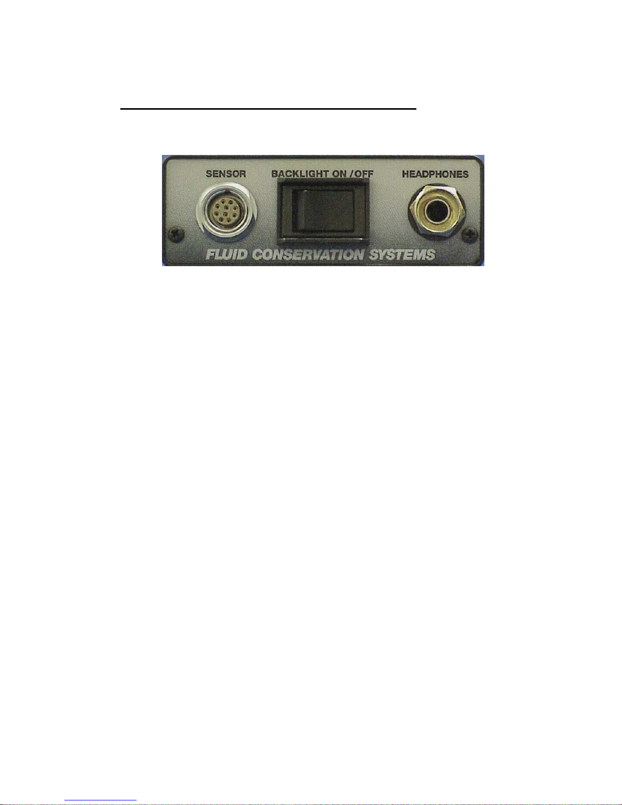
Rear Panel
Diagram I – Rear Panel
3.1 SENSOR CONNECTOR: Accepts the male LEMO plug from
the AX80 transducer.
3.2 TRANSDUCER (SENSOR) CABLE: The AX80 transducer is
provided with a rugged 10 ft. cable. This cable is mounted to
the transducer by means of a screw-on type connector. This
allows for replacement of the cable in case of damage to a
connector or the cable itself. Under typical day-to-day use, the
cable should remain attached to the transducer. The connector
assembly has been mounted to the transducer and packed with
a special purpose silicone grease to waterproof the sensor and
to prevent corrosion of the terminals.
Note:
WHENEVER THE CONNECTOR/CABLE ASSEMBLY IS
DISCONNECTED FROM THE TRANSDUCER, REPACK THE
CONNECTOR WITH A DAB OF G.E. #661 SILICONE GREASE. DO NOT
USE ANY OTHER SUBSTANCE.
3.3 BACKLIGHT SWITCH: Controls the backlight mode of the unit.
To enable the meter backlight, press the switch into the “ON”
position. To turn the backlight off, select the “OFF” position.
3.4 HEADPHONE/CABLE JACK: Used to provide the audio output
to the operator. For survey, insert the headphone plug into the
jack to monitor the output.
 Loading...