

Page 1
DESCRIPTION
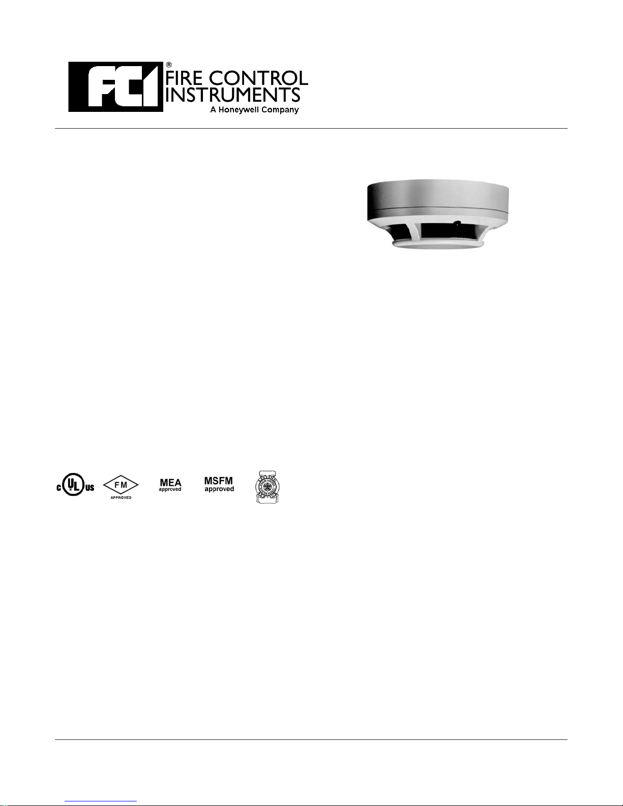
The System Sensor 2151 low profile photoelectronic
smoke detector is specifically designed to meet the perfor
mance requirements of fire detection/alarm systems. The
2151 detector uses a state-of-the-art optical sensing chamber
and is designed so that LED failure will not cause an alarm.
The detector is designed to provide open area detection, and
when installed ina two-wire base,is compatible with FCIfire
alarm control panels. The detector’s operation and sensitiv
ity can be tested in place.
The 2151 detector is of plug-in construction and plugs into
the same base as the 1151 ionization smoke detector, mak
ing both models interchangeable. Bases are available for
two-wire, four-wire, and 120 VAC four-wire operation, and
also with an audible sounder.
Two visible LEDs on each detector flash every ten seconds
indicating that power is being applied to the detector. The
LEDs light steadily when the detector is in alarm. A remote
LED annunciator is available as an optional accessory.
The 2151 is UL Listed formounting insideducts up to a velocity of 3,000 FPM.
Functional testing is performed by placing a test magnet
against the cover. The LED on the detector should light
within 30 seconds.
Field metering of detector sensitivity may be performed
with the aidof a voltmeter andTest Kit, PartNo. MOD 400R.
APPROVALS
2151
SYSTEM SENSOR
LOW PROFILE, PHOTOELECTRONIC,
PLUG-IN SMOKE DETECTOR
-
-
-
FEATURES
• Low Profile Construction
• Easy Plug-in of the Head to Base
• Tamper-resistant Feature
• Test Switch
o
• 360
• Compatible with FCI Control Panels
• Audible Sounder Base (Optional)
• Field Metering of Detector Sensitivity
•
•
View Angle of Alarm LEDs
Removable Insect Screen and Cover
for Field Cleaning
Insect-resistant Screening (.020"/.508
mm Openings)
Sensitivity 3.0 %/ft. (nominal)
Operating voltage 8.5 - 35 VDC (24 VDC nominal)
Standby current 120 uA maximum
Operating temperature 32
Operating humidity 10 % - 93 % relative humidity
Air velocity 3,000 feet per minute maximum
Construction Off-white flame retardant plastic
Diameter 6.2 inches (15.5 cm) (flanged base)
Height 1.7 inches (4.2 cm)
Weight 3.6 oz. (104 g)
16 Southwest Park, Westwood, MA 02090 USA TEL: (781) 471-3000 FAX: (781) 471-3099
TECHNICAL SPECIFICATIONS
o
to 120oF(0oto 49oC)
An ISO 9001 Certified Company
9020-0583/Ver. 1.1
Page 2
FIRE CONTROL INSTRUMENTS, Inc.
MOUNTING
On a 4-inch square box with or without
•
plaster ring. Minimum depth 1.5 inches.
On a 3.5-inch octagonal box. Minimum depth
•
1.5 inches.
INSTALLATION
Place the detector into the detector base. Turn the de
tector clockwise until the detector locks into place.
To use the tamper-proof feature, break the smaller tab
on the scribed line inthe tamper proof tab locatedon the
detector mounting bracket. Install the detector. To re
move the detector from the base when using the tam
per-proof feature, insert the blade of a small
screwdriver into the hole on the side of the base and
push the plastic lever away fromthe detector head. This
will allow the detector to be rotated counterclockwise
for removal. NOTE: The decorative ring must be re
moved in order to remove the head when using the tam
per-proof feature.
The tamper-proof feature may be defeated perma
nently by breaking the plastic lever off the base.
NOTE: The number of two-wire smoke detectors
which can be accommodated per zone varies with different control panels. Consult the control panel in-
struction manual to determine the capacity.
Refer to NFPA72, Chapter 5-3, “Smoke SensingFire
Detectors” for spacing, location of detectors and other
guidelines.
-
-
-
-
-
-
TESTING
Detectors may be tested in the following ways:
• Place a test magnet against the detector as
directed in the installation instructions. The
detector should go into alarm within 30
seconds.
•
Field metering of detector sensitivity may be
performed with the aid of a voltmeter and
Test Kit, MOD 400R.
For the complete procedure, refer to the Installation
and Maintenance instructions furnished with each
detector.
ORDERING AND TECHNICAL INFORMATION
Part No. Model Contacts Description
2151 Photoelectronic Detector
B110LP Base, Two-wire
301BL4 Form A & C Base, four-wire, 24 VDC operation
301BL4AC Form A, C & Supv. Base, four-wire, 120 VAC operation
B401BH Base, four-wire, with audible sounder
RA-400Z Remote Alarm Indicator
PAM-1 Form B End of Line Relay, 24 VDC
Test Kit
MAINTENANCE
Cleaning programs should be adapted to the individ-
ual environment in conformance with NFPA Standard
72. We recommend at least an annual cleaning of the
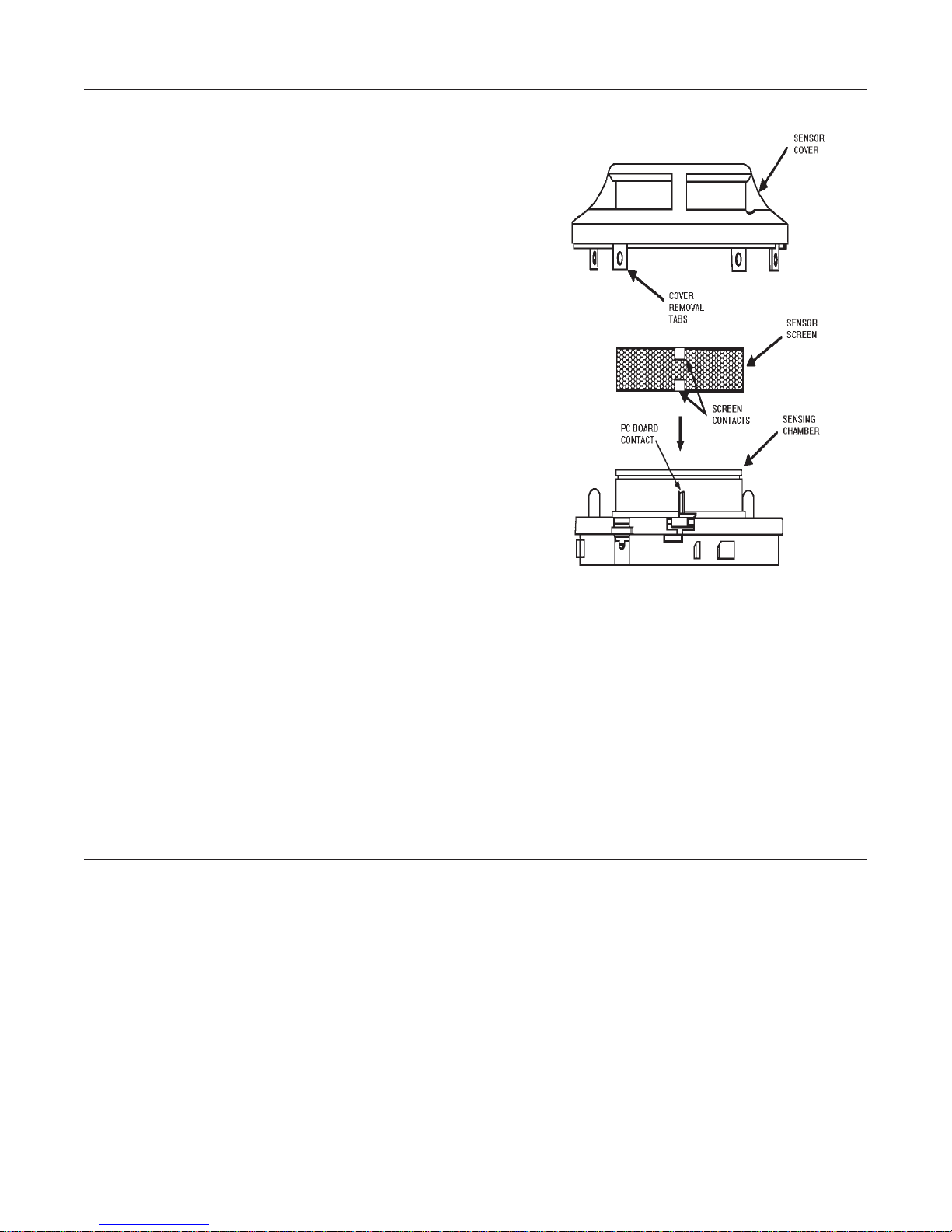
unit. The detector screen and cover assembly can be re
moved, revealing the sensing chamber. A vacuum
cleaner can be used to remove dust from the screen,
cover and sensing chamber. For the complete proce
dure, refer to the Installation and Maintenance instruc
tions furnished with each detector.
-
-
-
Specifications are provided for information only, are not intended to be used for installation purposes, and are believed to be accurate. However, no responsibility is assumed by Fire Control
Instruments, Inc. for their use. Specifications subject to change without notice. © 2003 All Rights Reserved
2of2 9020-0583
 Loading...