

Page 1
24 Hour Factory Service Hot Line: 1 (800) 854-1993
Document 06EN003322 Rev. -
12-64B, 8-66B Installation, Operation and
Troubleshooting Guide
Step 1. Pre-Installation
A. To get the best results, the sensor should be mounted 20 pipe diameters downstream from any flow disturbance
(valve, pipe elbow) and 10 pipe diameters upstream from any disturbance.
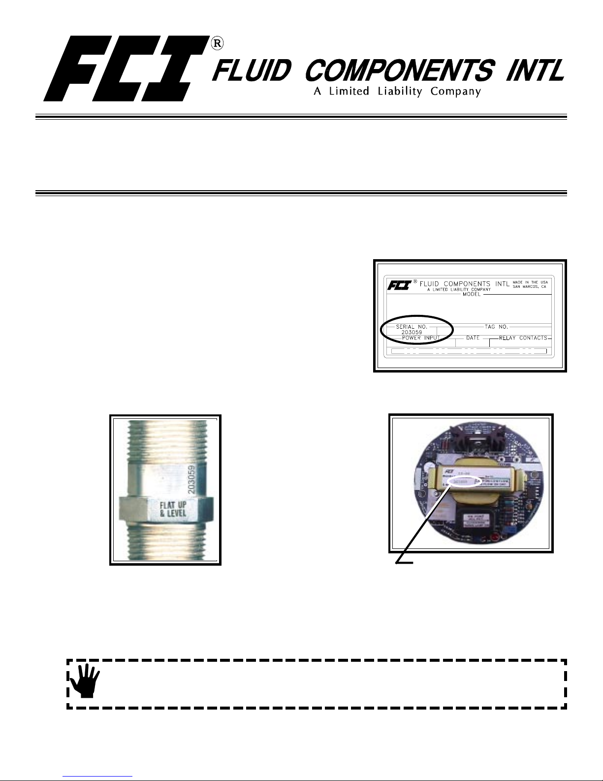
The instrument tag shows the model number, tag number (if
noted on the order) and serial number along with other
important safety information. Compare this information with the
appropriate pipe installation drawings to be sure the instrument
is the correct configuration. Match the tag serial number on the
enclosure, flow element and control circuit.
Tag Location
On the top side of the local enclosure
B. Verify the serial numbers on the enclosures, flow element and electronics (control circuit) match. The instrument
may not work if the serial numbers do not match.
Flow Element Serial Number.
Also Showing Sensor Orientation Flat.
(Located near the enclosure.
It is also on the enclosure tag.)
Electronics Serial Number
C. Recommended installation/troubleshooting tools are a 1-3/8 inch open ended wrench to fit the NPT connection, a
small flat blade screw driver for manipulating potentiometers, a medium flat blade screwdriver for tightening
connections, 3 mm allen wrench for CENELEC approved instruments, and a DVM for Ohm/Voltage
measurements.
Step 2. Flow Element Installation
Alert: DO NOT change the orientation of the flow element in the enclosure as the interconnecting RTD and
heater wiring could be stressed and damaged. DO NOT apply any torque to the flow element
enclosure - only apply to the pipe surface itself.
Install the flow element, with the Flat Up and Level (shown above) or parallel to the flow media (±2°) for top mounted
instruments. The enclosure, flow element and electronic control circuit card serial numbers should all match.
Page 2
When mounting the instrument the correct orientation of the flow element must be maintained to ensure repeatability to
within specifications.
Apply sealant to the male threads.
Carefully place in the process media line with the machined flat facing up.
Tighten the process connection. To avoid leaks do not overtighten or cross-thread connections.
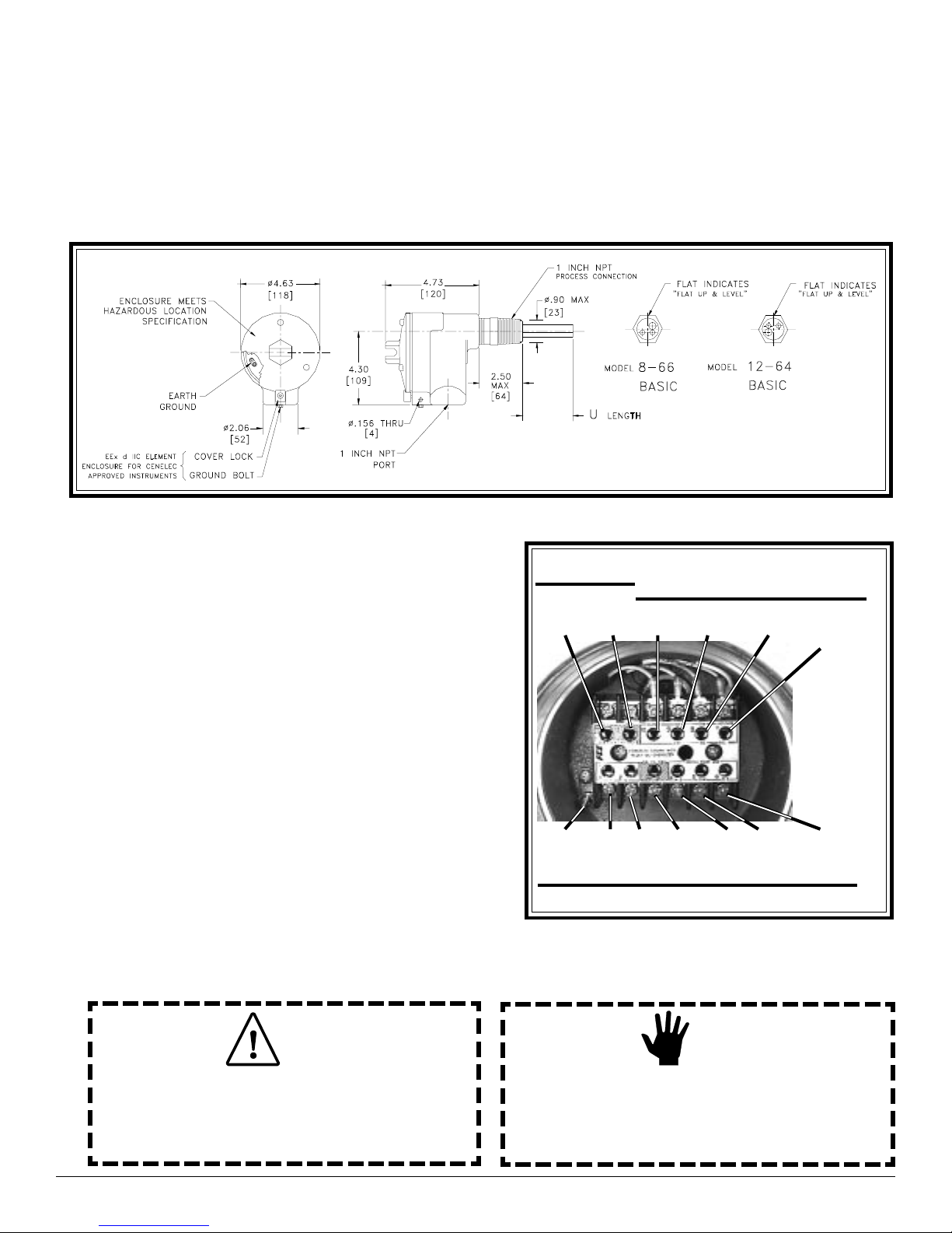
Shown below is the 1 inch NPT mounting.
12-64 Flow Switch and 8-66 Level Switch Installation and Outline Drawing
Step 3. Wiring Preparation
Before the instrument is opened to install the wiring, FCI
recommends that the following ESD precautions be
observed: Use a wrist band or heel strap with a
1 megohm resistor connected to ground. If the instrument
is in a shop setting there should be static conductive mats
on the work table and floor with a 1 megohm resistor
connected to ground. Connect the instrument to ground.
Apply antistatic agents such as Static Free made by
Chemtronics (or equivalent) to hand tools to be used on
the instrument. Keep high static producing items away
from the instrument such as non-ESD approved plastic,
tape and packing foam.
The above precautions are minimum requirements to be
used. The complete use of ESD precautions can be found
in the U.S. Department of Defense Handbook 263.
Open the instrument enclosure to wire the instrument.
Remove the control circuit by lifting and rocking the
circuit board back and forth to expose the terminal block
as shown. The wiring connections are then accessible.
Step 4. Wiring the Instrument
CUSTOMER
WIRING
N/O
ALARM
# 2
SAFETY
GND
N/C
ALARM
# 2
PWR PWR
FACTORY WIRING
N/O
ALARM
# 1
(COM 8)
(COM 8)
COM
ALARM
# 1
(HTR 10)
AC or DC
(+) (-)
CUSTOMER WIRING
(REF 9)
COM
ALARM
# 2
12-64/8-66 Wiring Pictorial
(HTR 7)
(ACT 7)
N/C
ALARM
# 1
Caution:
Only qualified personnel are to wire or test this instrument.
The operator assumes all responsibilities for safe practices
while wiring or troubleshooting.
Model 12-64/8-66 2 Doc. No. 06EN003322 Rev.-
Alert:
The instrument contains electrostatic discharge (ESD)
sensitive devices. Use standard ESD precautions when
handling the control circuit.
Page 3
INSTALLATION, OPERATION AND TROUBLESHOOTING GUIDE FLUID COMPONENTS INTL
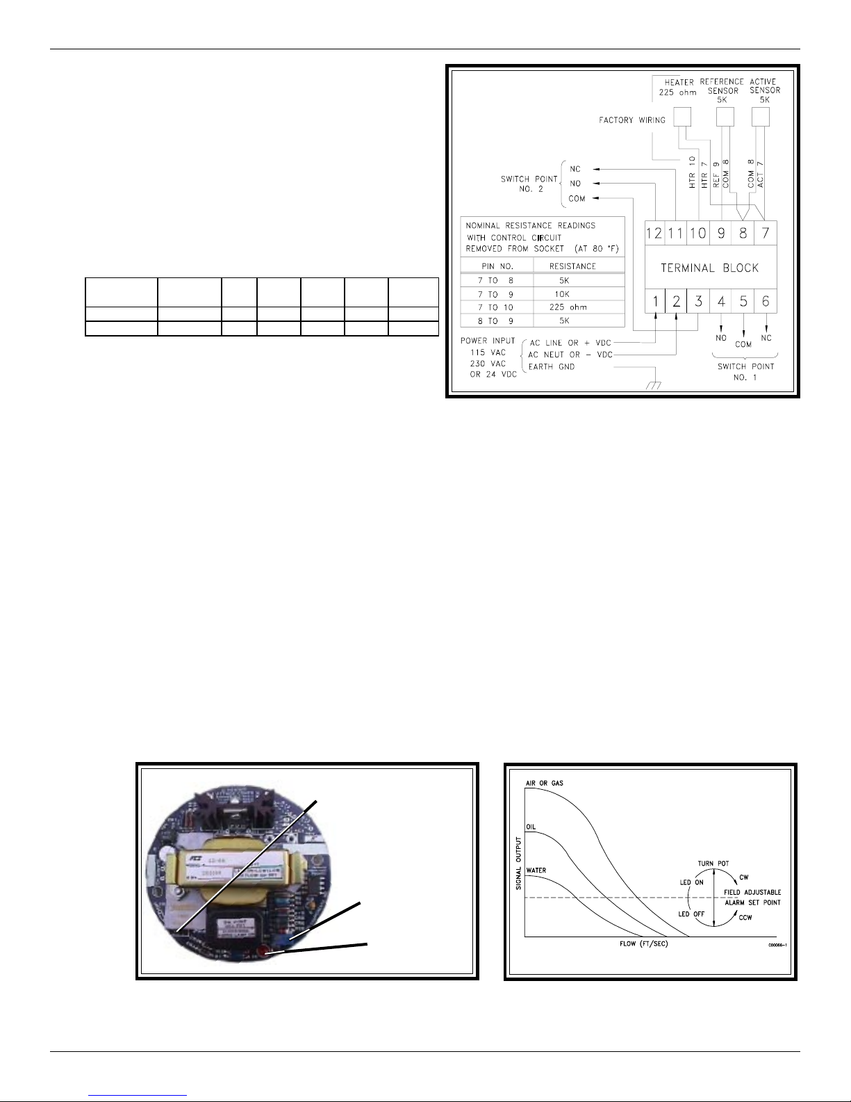
Wiring the Instrument into the Customer’s Application:
FCI recommends routing conduit to the enclosure.
Below is a table to determine the wire size needed to route
to the instrument. Connect the customer’s application
(relays, lights, etc,.) to the terminal block switch points as
required. The input power is either 115 VAC, 230 VAC
or 24 VDC and was specified when the instrument was
purchased. Check the part number or paperwork received
with the instrument to determine the type of power to be
applied to the instrument. Connect the power as shown.
Maxim um Distance for AWG
Connection 10 ft. 50 ft. 100 ft. 250 ft. 500 ft. 1000 ft.
(3 m ) (15 m ) (31 m ) (76 m ) (152 m ) (30 5 m )
Power 22 22222018 16
Relay 24 22201612 N/A
Step 5. Operation
12-64 Alarm Set Point Procedure:
1. Set the flow at the desired rate.
Wiring Diagram
2. Apply power to the instrument and allow 10 minutes for the sensing element to become active and stabilize.
3. Locate the potentiometer (R5) and the red LED on the control circuit. (See the picture below:)
4. Choose procedure A or B below.
A. Detecting No Flow or Decreasing Flow Rate
If the LED is off, turn the potentiometer clockwise until the LED turns on. If the LED is on, turn the potentiometer
counterclockwise until the LED turns off, then turn the potentiometer clockwise until the LED just turns on. With the
LED on, turn the potentiometer slowly counterclockwise until the LED just turns off. Turn the potentiometer one-half
turn past the point at which the LED just turns off. Be aware that the potentiometer may have up to one quarter turn of
hysteresis. If the mark is overshot, the procedure should be repeated. (See the picture and diagram below:)
B. Detecting Maximum Flow or Increasing Flow Rate
If the LED is on, turn the potentiometer counterclockwise until the LED turns off. If the LED is off, turn the
potentiometer clockwise until the LED turns on, then turn the potentiometer counter clockwise until the LED just turns
off. With the LED off, turn the potentiometer slowly, clockwise until the LED just turns on. Turn the potentiometer
one-half turn past the point at which the LED just turns on. Be aware that the potentiometer may have up to one quarter
turn of hysteresis. If the mark is overshot, the procedure should be repeated. (See the picture and diagram below:)
Jumper on J12.
J12, J13
Relay de-energized
at no flow / dry.
Jumper on J13.
Relay de-energized
at flow / wet.
12-64/866 Plug and Switch Orientation
5. Test switch operation by increasing or decreasing the flow to activate the alarm.
Doc. No. 06EN003322 Rev.
-
R5, set point
potentiometer.
Set point LED.
Setting Alarm Switch Point
3 Model 12-64/8-66
Page 4
8-66 Alarm Set Point Procedure
Adjustment With The Sensing Element Wet
1. Determine that the sensing element is wet.
2. Apply power to the instrument and allow 10 minutes for the sensing element to become active and stabilize.
3. Locate the potentiometer (R5) and the red LED on the control circuit. (See the picture on the previous page.)
4. If the LED is off, turn the potentiometer clockwise until the LED turns on. With the LED on, turn the potentiometer
slowly, counterclockwise one quarter turn past the point at which the LED just turns off. The potentiometer may
have up to a quarter turn of hysteresis in either direction. If the mark is overshot, repeat the procedure.
Note:
Give consideration that significant amounts of air or gas flowing over the sensing element may lower the
sensor dry signal, resulting in a false indication of wet.
Step 6. Troubleshooting
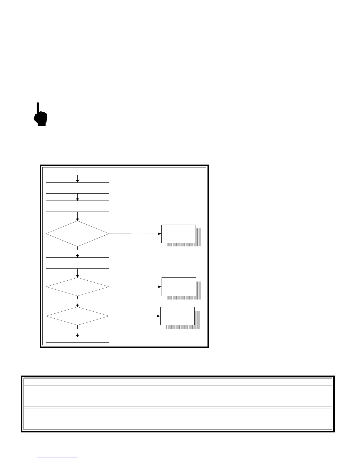
In the event that the instrument does not operate as expected use the following table.
Problem ?
Verify input power to
the instrum ent.
Turn power OFF.
Rem ove control circuit.
Verify HTR and
RTD Resistance
Pass
R e in s ta ll co n tr o l c ir c u it.
Turn power ON .
Fail
STOP
C a ll F C I fo r
instructions.
Other Quick Checks:
Check the jumper positions of J12
and J13. Jumper J12 energizes the
relay at flow/wet. Jumpers J13
energizes the relay at no flow/dry.
Check that the control circuit is
firmly seated into it's socket.
Check if power is present and
customer fuses are good, if they are
used.
V erify contro l
circuit voltages.
Pass
Sim ulate alarm
condition.
Pass
END
Fail
Fail
STOP
C a ll F C I fo r
in s tr u c tio n s .
STOP
C a ll F C I fo r
in s tr u c tio n s .
If there are still problems, see the Troubleshooting Section in the 12-64/8-66 Series Manual, Document
Number 06EN003264. To acquire a manual call your local FCI sales representative.
Notice of Proprietary Rights
This document contains confidential technical data, including trade secrets and proprietary information which are the property of Fluid Components Intl
(FCI). Disclosure of this data to you is expressly conditioned upon your assent that its use is limited to use within your company only (and does not include
manufacture or processing uses). Any other use is strictly prohibited without the prior written consent of FCI.
Visit FCI on the Worldwide Web: www.fluidcomponents.com
1755 La Costa Meadows Drive, San Marcos, California 92069 USA - 760-744-6950 - 800-854-1993 - Fax 760-736-6250
European Office: Persephonestraat 3-01 5047 TT Tilburg - The Netherlands - Phone 31-13-5159989 - Fax 31-13-5799036
© Copyright 2001 Fluid Components Intl a limited liability company All Rights Reserved
Model 12-64/8-66 4 Doc. No. 06EN003322 Rev.-
 Loading...