

Page 1
K5-EN-V3
Emergency Weather Channel Receiving/Fast Copy One Channel/VOX/
Multi-Band Transmitting and 50∽600MHz Receiving/Remote Kill
/Revive/Type-C and Charger-base Charging/200 Channels
Page 2

FCC WARNING
■FCC Compliance Statements:
This device complies with pa 15 of the FCC Rules.
Operation is subject to the following two conditions:
(1) This device may not cause harmful inteerence, and
(2) this device must accept any inteerence received, including
inteerence that may cause undesired operation.
Changes or modications not expressly approved by the pay responsible for
compliance could void the user's authority to operate the equipment.
Note: This equipment has been tested and found to comply with the limits for a
Class B digital device, pursuant to pa 15 of the FCC Rules. These limits are
designed to provide reasonable protection against harmful inteerence in a
residential installation. This equipment generates, uses and can radiate radio
frequency energy and, if not installed and used in accordance with the instructions,
may cause harmful inteerence to radio communications. However, there is no
guarantee that inteerence will not occur in a paicular installation. If this
equipment does cause harmful inteerence to radio or television reception, which
can be determined by turning the equipment o and on, the user is encouraged
to t to correct the inteerence by one or more of the following measures:
—Reorient or relocate the receiving antenna.
—Increase the separation between the equipment and receiver.
—Connect the equipment into an outlet on a circuit dierent from
that to which the receiver is connected.
—Consult the dealer or an experienced radio/TV technician for help.
This device complies with FCC radiation exposure limits set foh for an
uncontrolled environment. Do not use this device when the antenna shows
obvious damages.
Hold this transmitter approximately 25 mm away from your face and speak
normal with the antenna pointed up and away. Use the supplied belt clip for
body-worn conguration as other accessories may not comply to the limits.
WARNING: MODIFICATION OF THIS DEVICE TO RECEIVE CELLULAR
RADIOTELEPHONE SERVICE SIGNALS IS PROHIBITED UNDER
FCC RULES AND FEDERAL LAW.
■Licensing Information
Use our radio in USA is subject to the rules & regulations of FCC.
Changes or modications not expressly approved by our may void the user
authority granted by the FCC to operate this radio and should not be made. To
comply with FCC requirements, transmitter adjustments should be made only by
or under the supeision of a person ceied as technically qualied to peorm
transmitter maintenance and repairs in the private land mobile and xed seices
as ceied by an organization representative of the user of those seices.
Replacement of any transmitter component (cstal, semiconductor, etc)
not authorized by the FCC equipment authorization for this radio could violate
FCC rules.
Page 3

Note: Use of this radio outside the count where it was intended to be
distributed is subject to government regulations and may be prohibited.
Impoant: Any changes or modications not expressly approved by
the pay responsible for compliance could void the user's authority
to operate this device.
Your radio is set up to transmit a regulated signal on an assigned frequency.
It is against the law to alter or adjust the settings inside the radio to exceed those
limitations. Any adjustments to your radio must be made by qualied technicians.
CE WARNING:
Use the two way radio in the environment with the temperature between
0-40℃,otherwise,it may damage your two way radio . It can be operating
under 2000m.
Hereby, Our declare that the radio equipment type two way radio is compliance
with Directive 2014/53/EU. For this device,Head SAR and Body SAR was peormed
with the device congured in the positions according to EN62209-2�2010,and
face-up SAR was peormed with the device 25mm from the phantom,and Body
SAR was peormed with the device 0mm from the phantom. Body SAR was also
peormed with the headset and belt clip attached and without.
PRECAUTIONS BEFORE USING
This radio incorporates excellent design and the latest advanced technology.
The following advice will help you fulll your obligations in the warranty clause. And
it gives you impoant information about how to operate this poable radio safely.
◆ Please put the radio and accessories where the children cannot reach.
◆ Maintenance can only be peormed by professional technicians.
◆ Please use the standard batte pack and charger in order not to
destroy the radio.
◆ Please use the standard antenna, in order not to shoen the
communication distance.
◆ Do not expose the radio to sunlight for a long period of time,
nor put it near the heat.
◆ Do not put it in extreme dust or wet environment.
◆ Do not clean the radio with erce chemical products, cleaning
agents or strong washing agents.
◆ Do not transmit when the antenna is not installed.
◆ If you nd bad smell or smog, please turn o the radio immediately.
And take the batte o the radio, then contact with the agent.
Charging Notes:
◆ Batte packs are not charged when they are shipped. Charging them before use.
◆ Initially charging the batte pack after purchase or extended storage
(longer than 2 months) will not bring the batte pack to its greatest
capacity or its normal charge, which can be done only after repeated
charging and discharging two or three times.
Page 4

Type-C charging instructions:
◆ Do not use the radio during charging. This will aect the normal charging
of the batte pack, causing damage to the radio and accidents.
◆ After the batte pack is fully charged, please take it out of the charger-base.
Do not charge it again before the batte is completely running out. Or it will
destroy the memo eect of the batte.
◆ Although using the right charging ways, but the batte does not
gain capacity or using time, it means the batte life is near the end,
please change a new batte pack.
◆ Please adopt original facto batte pack and charger.
They are available with your local agent.
◆ If you have question about non original facto batte pack and
accesso, please do not use them. Or it will cause dangerous accidents.
Charging-base instructions:
◆ Plug the lithium batte or radio equipped with the lithium batte
into the charger base, and ensure that the batte is in normal contact
with the charging base.
◆ The green light is steady on when the charging base is empty; When the
red light is on, charging begins; When full, the green light is steady on.
◆ After the lithium batte pack is fully charged, take it out of the charger.
◆ Type-C charging is only used for emergency charging. Use charging
base for normal charging.
◆ The shutdown does not aect the charging of Type-C.
◆ When charging, the blue light will be on for a long time, and the blue
light will blink to indicate that the charging is about to be completed.
At this time, it is a small current charging.
◆ After Type-C is charged, the blue light will be turned o.
◆ Do not remove the batte when charging through Type-C.
There are two versions of this series:
(A) body with Type-C charging; (B) body does not have Type-C charging
The conguration of the product is as what your real purchase.
Note:
1. When the radio is charging (charger /Type-C charging), it is forbidden to transmit
so as to avoid damage to the radio and accidental danger.
2. When the radio is charged (charger /Type-C charging), the receiving eect will
be aected.
3. Do not sho circuit the batte terminal or discard the batte in the re.
4. Do not remove the batte pack cover without permission.
Page 5
Main Feature
10 Emergency Weather Channels
Multi-Band Transmitting and
50∽600MHz Full Band Receiving
AM/FM Aviation Band Receiving
Cross-Band Intercom
Fast Frequency Matching
Act as Frequency Meter
Wireless Radio Replication
Emergency Ale
FM Radio
10-Group Scrambler
Multi-Scan
CTCSS/DCS
High Capacity Batte/Long Standby Time
One Key Call Channel
Type-C And Base Charging
Jacklight
H/M/L Output Power Selective
VOX
Dual-watch Operation
Receive/Transmit Code Setting Separately
Oset Frequency Direction Setting
DTMF Calling
DTMF ANI
DTMF Select Call (single call, group call,all call)
Power-on Password Protection
Reverse Frequency Function
Multi Step Frequency
Oset Frequency Setting
Busy Channel Lock
Time-Out-Timer
Channel No./Channel Frequency/
Channel Name Multi-display Mode
Wide/Narrow Bandwidth
Reset Function
1750HZ Call Tone
Squelch Level Adjustable
Onsite Programming
Frequency and Channel Mode Shift
Keypad Lock
Channel Scan and Add
200 Channels
PC Programmable
Large LCD Display
Voice Prompt
Reminding Switch
Backlight Auto O Time Selective
Repeater Forwarding Conrmation Function
Auto Code Search
Remote Kill/Revive
Custom Staup Image
(Only suppoed by some models)
CONTENTS
1.Complete Radio Accessories
2.Radio Diagram
3.LCD Display
4.Key
1.PTT Key (Transmitting Key)
2.Programmable Function Key and Its Function
3.Keypad Key
5. Menu Info
6. Common Operation Introduce
(1)Power On Password Protection
(2)Switch Main Channel
(3)Dual Band Single-Watch/Dual-Watch Switch
(4)Frequency/Channel Mode Switch
(5)Cross-Band Receiving/ Transmitting
(6)Edit the Channel Name
(7)Channel Save
(8)Channel Delete
(9)Receiving/ Transmitting CTCSS/DCS Setting
(10)Frequency Meter/Fast Copy One Channel
(11)Auto CTCSS/DCS Search
(12)DTMF
12-1 DTMF Calling
12-2 PTT-ID
(13)Scan
(14)Emergency Alarm
(15)FM Radio
(16)NOAA Receiving
(17)Keypad Locking
(18)Reset
(19)One Key Call Channel
(20)Aviation Band Receiving
(21)Wireless Radio Replication
7.Specications (1)
Specications (2)
01
02
03
04
04
04
04
06
09
09
09
09
09
10
10
10
11
11
11
12
12
12
13
13
14
15
15
15
15
16
16
16
17
18
Page 6
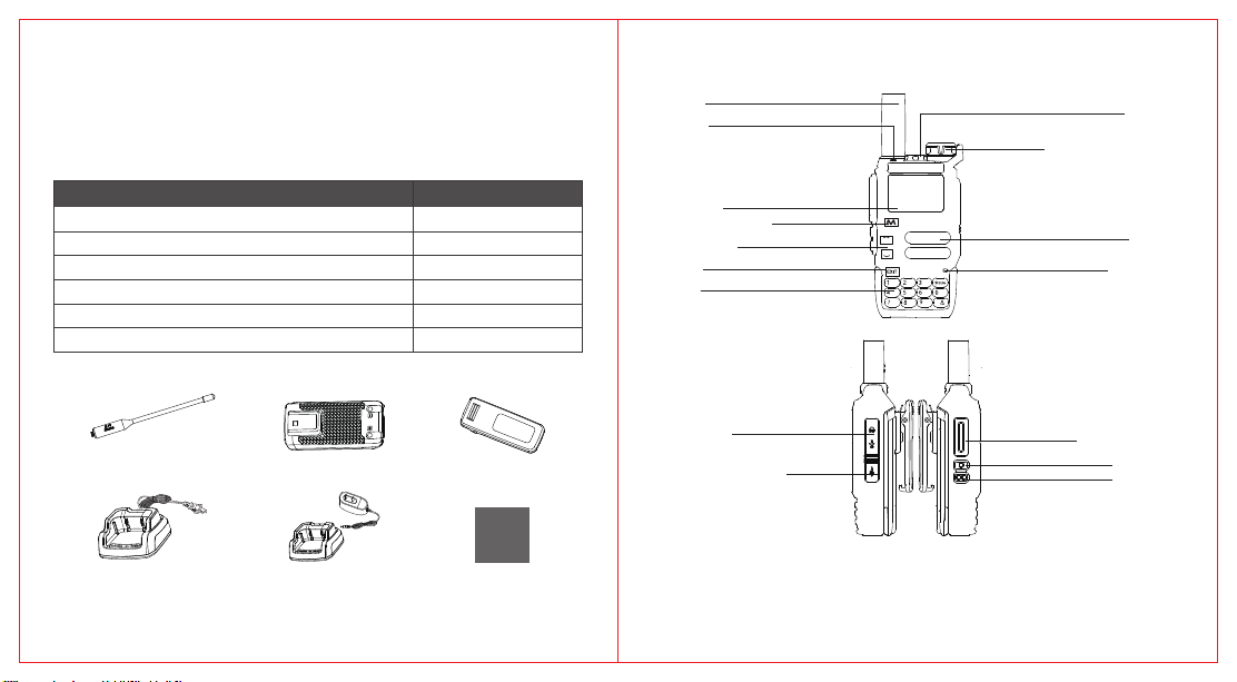
Complete Radio Accessories
Carefully unpack the poable radio. We suggest that you check the following
items before you throw away the packing materials.
Random Accesso List
Item
Poable Radio
Antenna
Li-ion Batte
Batte Charger
Belt Clip
User's Manual
Qty
1
1
1
1
1
1
Accessories Photo
Radio Diagram
Antenna
Indicator
Indicator Detail:
1.Red Light----- Transmitting
2.Green Light-----Receiving
3.Blue Light-----On when Charging/
O when the radio is full charged.
LCD Screen
Menu(Conrm Key)
Up/Down Key
Exit Key
Keypad
A
B
C
D
Band A/B
NO
FC
AA
VOXRCall
Jacklight
Power/Volume Switch
Turn on the radio by clockwise direction;
Turn o the radio by counterclockwise
direction. Turn clockwise to increase volume,
counterclockwise to decrease volume.
Speaker
VFO
MR
H/
FM
M/L
F
Microphone
Antenna
Batte Charger
Li-ion Batte
Separate Charger (Optional)
Belt Clip
TWO-WAY
RADIO
User’s Manual
Emergency Weather Channel Receiving/Fast Copy One Channel/VOX/
Multi-Band Transmitting and 50∽600MHz Receiving/Remote Kill
/Revive/TPYE-C and Charger-base Charging/200 Channels
User's Manual
Microphone/
Programming Jacks
TYPE C Charging Po
Type-C charging po is for
emergency charging only.
Do not remove the batte
when using Type-C charging.
Type-C charging function of this series of products is optional.
The conguration of the product is as what your real purchase.
Transmitting Key
Side Key 1
Side Key 2
Programmable Function
Key, See Page 04
01 02
Page 7
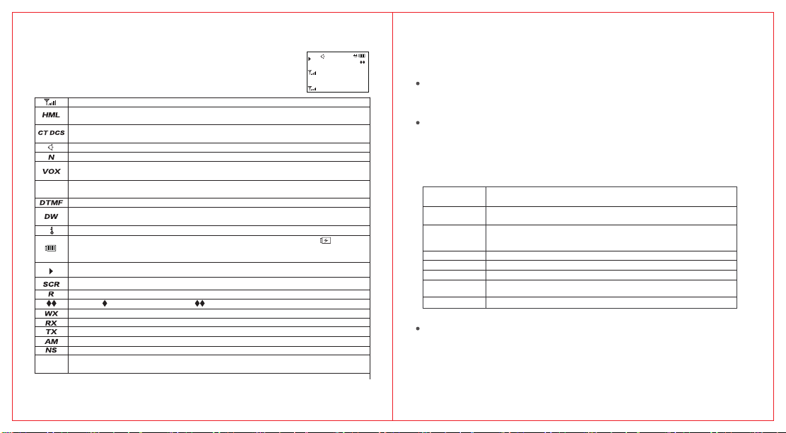
LCD Display
NS
DW
M1
You could check the dierent designated symbols in the LCD.
The following cha helps you to understand them.
Signal Strength. The smaller the number of grids, the weaker the signal.
Transmitting Output Power Indicator.
The current transmitting output power is high(H), medium(M) or low(L).
CT will appear when current code is CTCSS code.
DCS will appear when current code is DCS code.
Voice prompt is on.
The radio work in narrow band mode.
VOX Function. When the sound pressure reaches the set value, the
transmission is staed. This function can be set through the menu.
+ It means transmitting frequency equals receiving frequency plus a frequency deviation
+ -
- It means transmitting frequency equals receiving frequency minus a frequency deviation
DTMF signal decoding is on.
Frequency dual watch is on. Could dual watch the two frequency
bands show on the display
Keypad locking.
Display of the current batte. When the batte is nearly exhausted, it shows .
It means the batte needs to charge and the radio will send low power alarm prompt
regularly.
Main channel indicates, keypad and all menu operations will work on main channel.
The voice encption of this channel is on.
Talk around mode. Receive and transmit frequency reverse
Scanning. Paicipating in scan list 1. Paicipating in scan list 2.
Cross-Band Receiving/Transmitting.
Receiving.
Transmitting.
AM receiving mark
NOAA channel atuomatic scan
Tempora transmitting channel, when sub-channel receives a call,
>
it becomes tempora transmitting channel.
03 04
89
RX
>
F6
435.250
DCSL-
435.250
H
00
00
Key
PTT Key(Transmitting Key)
Transmitting/Receiving Switch Key. Press “PTT” to transmit and speak to
microphone. Release “PTT” to receive.
Programmable Function Key and Its Function
Initial Function
Side Key 1: Press it for a sho time to turn on Monitor function.
Press it for a long time to turn on 1750Hz.
Side Key 2: Press it for a sho time to turn on Jacklight.
Press it for a long time to turn on emergency alarm.
The function of the side key that could be set by program software:
Emergency
Mode On/O
Output Power
Selection
Monitor
FM Radio
Scan On/O Allow user to turn on/turn o Scan function.
VOX On/O Allow user to turn on/turn o VOX function.
Transmitting
1750
Jacklight
Keypad Key
Menu /Conrm Key
A. In main page, sho press it to enter the menu, choose menu
item and press MENU key to conrm the parameter.
B. Long press this key to enter the last setting item.
C. Under the DTMF Function, it means A code word.
Press it to turn on Emergency Alarm. It will alarm as
the setting of program software.
Allow user to switch between LOW/MID/HIGH output power.
Allow user to turn on/turn o Monitor function.
The radio will ignore all receiving CTCSS/DCS, and monitor the
actual channel. You can listen to monitor noise to adjust volume.
Turn on/turn o FM Radio Mode.
Turn on 1750 continuous transmitting.
Turn on/ turn o Jacklight
Page 8
Exit/Clear Key
A. In Edit status, sho press it to exit and come to upper menu;
long press it to exit and come to main page.
B. In Input status, press it to clear the input info.
C. Under the DTMF Function, it means D code word.
Up Shift Key
A.Moves Up.
B.Represents the "B" code in DTMF mode.
Down Shift Key
A. Moves Down.
B. Represents the "C" code in DTMF mode.
* Key
A. Sho press * Key to enter manual dial and call page
B. Under the DTMF function, it means * code word.
C. Long press * Key to sta frequency or channel scanning.
F Key
A. It could work with 0-9 and * to quickly implement function switching.
B. Long press this key to lock or unlock the keyboard.
C.Under the DTMF , it represents the # code word.
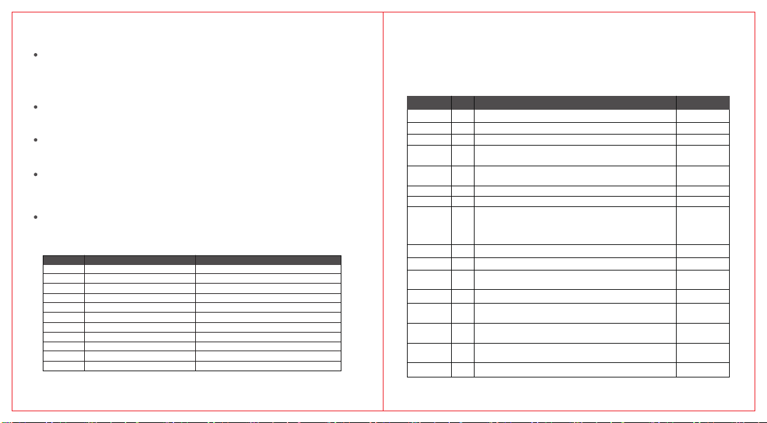
Fast Key Function Function Description
F+1
F+2
F+3
F+4
F+5
F+6
F+7
F+8
F+9
F+*
F+0
05 06
BAND
A/B
VFO/MR
Frequency Meter
Emergency Weather Channel
H/M/L
VOX
R
CALL
SER
FM
(F1-F7)Frequency Switch
Main Channel Switch
Switch between VFO and MR Mode
Sta Fast Copy One Channel
Sta or Exit Listening
Switch Output Power
Switch to VOX
Switch to Reverse Function
Switch to One Key Emergency Calling
Sta CTCSS/DCS Search Function
Sta or Exit FM
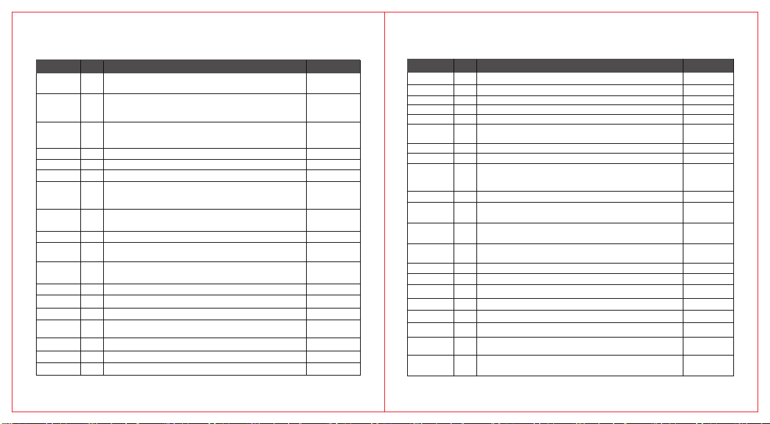
Press Menu key to enter Menu Selection; Press UP/Down Key to select Menu No., and
press MENU Key to conrm the selection; Press EXIT Key to return to Upper Menu. Long
press EXIT key to return to main page.
(There may be among some models, please refer to the actual radio).
Item Name No. Function Description Value Range
01
SQL
STEP
TXP
R_DCS
R_CT CS
T_DCS
T_C TCS
SFT-D
OFFSET
W/N
SCR
BCL
CHNAME
SAVE
VOX
Squelch Level
02
Step Frequency(2.5K/5K/6.25K/10K/12.5K/25K)
03
Output Power(LOW/MID/HIGH)
Receive DCS(OFF,1-104:DCS, 105-208: reverse DCS).
04
Sho Press F+* to trigger DCS to scanning.
Receive CTCSS.(OFF, 1-50:CTCSS).
05
Sho Press F+* to trigger CTCSS scanning.
Transmit DCS(OFF, 1-104: DCS, 105-208:reverse DCS)
06
Transmit CTCSS(OFF, 1-50:CTCSS)
07
Frequency Deviation Setting(OFF:TX frequency
=RX frequency; ADD: TX frequency=RX
08
frequency + frequency deviation; SUB: TX
frequency=RX frequency-frequency deviation)
09
Frequency of Frequency Deviation(0-999.9999M)
Wide/Narrow Bandwidth Conguration﹙0:WIDE﹐1:NARROW﹚
10
Encpted Communication (OFF, 1-10: 1 to 10 types of
11
scrambling frequency.)
Busy Channel Lock(OFF,ON﹚
12
Press the MENU key to display and edit the channel name,
13
and press the # key to switch the input method
Channel Save (Choose the channel by UP/Down Key
14MEM-CH
and Number Key, press MENU key to save the channel.)
Batte Save(OFF/1�1/1�2/1�3/1�4)
15
The rate between active time and sleep time.
VOX Setting(OFF: turn o VOX, 1-10: 1 to 10 grade.)
16
0-9
0-5
0-2
0-208
0-50
0-208
0-50
0-2
0-1
0-10
0-1
0-4
0-10
Menu Info
Page 9
Menu Info
Menu Info
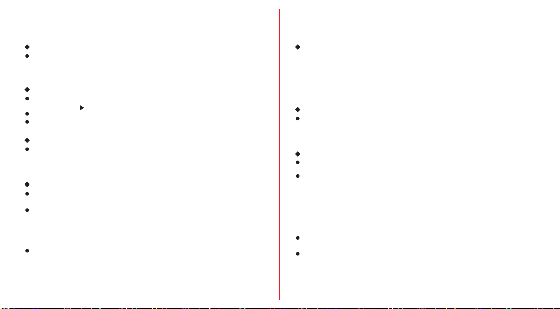
Item Name No. Function Description Value Range
ABR
TDR
WX
BEEP
TOT
VOICE
SC-REV
MDF
AUTOLK
S-ADD1
STE
RP-STE
MIC
1-CALL
S-LIST
07 08
Auto Backlight (OFF: turn o Backlight;
1-5: turn o Backlight in 1-5 seconds)
Dual-watch On/O (OFF: CHAN_A: Default TX
Channel is A channel, CHAN_B﹕ Default TX Channel is
18
B channel.)
Cross-Band Receiving/Transmitting (OFF:
CHAN_A: TX Channel is A channel,
19
CHAN_B:TX Channel is B channel.)
BEEP Control(OFF, ON)
20
Time-Out-Timer(1-10min)
21
Voice prompt (OFF,ENG,CHI)
22
Scan Resume Mode (TO: Resume scan after 5 seconds`
pause; CO: Resume scan after signal disappear; SE:
23
After receive the signal, stop scan.)
Channel Display Mode (FREQ: Display frequency, CH:
24
Display channel No., NAME: Display channel name)
Auto Keypad Lock(OFF,ON)
25
Whether to paicipate in list 1 scanning
26
(OFF: not paicipating, ON: paicipation)
Whether to paicipate in list 2 scanning
27S-ADD2
(OFF: not paicipating, ON: paicipation)
Tail Tone Elimination(OFF,ON)
28
Repeater Tail Tone Elimination(OFF,ON)
29
MIC Sensitivity (0-4: 0-4 level)
30
One Key Call Channel (Select the channel through the
31
UP/Down keys and the Number keys)
Channel Scan List Select (LIST1:Scan list 1﹔LIST2:Scan list 2)
32
Channel Scan List 1 Conguration
33SLIST1
Channel Scan List 2 Conguration
34SLIST2
0-517
0-2
0-2
0-1
1-10
0-2
0-2
0-2
0-1
0-1
0-1
0-1
0-1
0-4
1-2
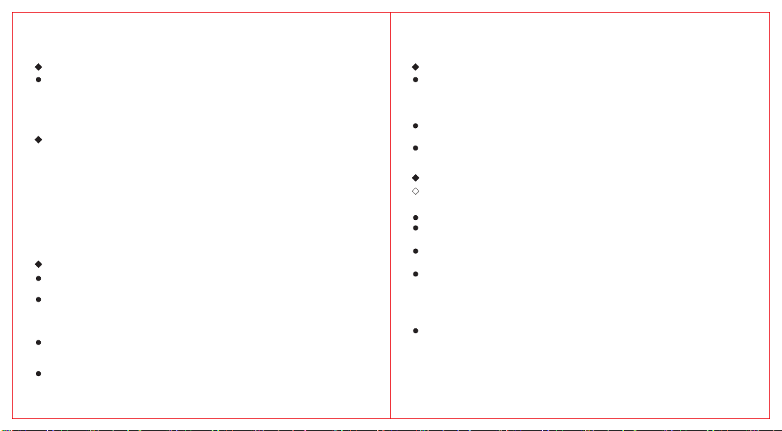
Item Name No. Function Description Value Range
Alarm Mode(SITE: local alarm; TONE: Distant + local alarm)
ANI-ID
UPCODE
DWCODE
D-ST
D-RSP
D-HOLD
D-PRE
PTT-ID
D-DCD
D-LIST
PONMSG
ROGER
VOL
AM
NOAA_S
LOGO1
LOGO2
Ver
DEL_CH
RESET
35AL-MOD
ANI-ID, DTMF communication radio ID
36
DTMF UP CODE
37
DTMF DOWN CODE
38
DTMF Side Tone Switch(OFF,ON)
39
DTMF Decoding Response (NULL: Close, Ring: Local ringing,
40
REPLY: reply response, both: local ringing +reply response)
DTMF Auto Reset Time(5s-60s)
41
DTMF pre-load time(30-990ms)
42
DTMF PTT-ID TX Mode(OFF: Close, BOT: Press PTT to
send UP CODE, EOT: Release PTT to send DOWN CODE,
43
BOTH: Press or release PTT to send.)
DTMF decoding enable signal (OFF,ON)
44
DTMF Contact List(Choose the contact by UP/Down Key and Number
45
Key, press MENU key to select the contact and call directly.)
Displays of Power On(FULL: Full-screen display, MSG:
46
Customized welcome message, VOL: Voltage, PIC Picture)
Reminding of End Talk(OFF: no reminding,
47
ROGER: with reminding, MDC: Frog Sound Tail Tone)
Batte Voltage
48
Switch modulation mode. ON:AM OFF:FM (Used only for 108-136MHz)
49
50
NOAA Channel Auto Scan On/O
Edit Power-On Welcome Character 1
51
Edit Power-On Welcome Character 2
52
Display the software version information.
53
Channel Delete (Choose the channel by UP/Down Key
54
and Number Key, press MENU key to delete the channel.)
Reset (VFO: Reset parameter excluding channel parameter;
55
ALL: Reset all parameter).
0-1
0-1
0-3
5-60
3-99
0-3
0-1
1-16
0-2
0-2
0-1
0-1
0-1
Page 10
Common Operation Introduce Common Operation Introduce
(1)Power On Password Protection
Turn the “Power/Volume Switch” in clockwise direction to power on this radio.
If the program set Power On Password Protection, then the screen will show
“LOCK”. The user has to input the password rst. Then the radio could be
normally used.
(2)Switch Main Channel
Press F+2 Key to switch main channel.
The solid arrow pointed to the main channel.
Press PTT to sta TX in main channel.
If sub channel receives a call, it displays > and temporarily becomes the TX
channel. After symbol > disappears, prima channel becomes TX channel again.
(3)Dual Band Single - Watch/Dual - Watch Switch
Dual-watch operation mode could be set by menu. The method is:
MENU →18→TDR, press MENU to enter and press the up and down keys to
select. CHAN_A: Default TX channel is A channel, or CHAN_B: Default TX
channel is B channel. The screen will show “DW”.
(4)Frequency/Channel Mode Switch
In main page, press F+3 key to switch between Frequency Mode and Channel
Mode.
Frequency Mode: In this mode, the users could manually input the RX frequency.
Or you could press UP/Down key to adjust the frequency by step frequency.
The parameter could be modifying by menu. In this mode, the users could not
input TX frequency. You could set Oset Frequency or Direction of Oset
Frequency to change the TX frequency.
Channel Mode﹕Display the actual channel No. In this mode, the users could
manually input the channel No.. Or you could press UP/Down key to switch
channel. The parameter could be modied by menu.
09 10
(5)Cross-Band Receiving/ Transmitting
The method is: MENU→19→WX﹐ press MENU to enter setting.
OFF: Main Channel TX when CHAN_A or B receives a valid call, the
channel automatically becomes the transmitting channel until the call ends.
CHAN_A:No matter which channels receive valid calls, Default TX
Channel is A channel, displaying the "WX" character.
CHAN_B:No matter which channels receive valid calls, Default TX
Channel is B channel, displaying the "WX" character.
(6)Edit the Channel Name
Edit the Channel Name in channel mode, press MENU->13->CHNAME and
press MENU again to enter, use the numeric keypad to select the desired
character, press the EXIT key to delete the previous character, and after
completion, press MENU to conrm and return to the upper menu.
(7)Channel Save
In MR Mode, Channel Save is workable. You could copy current
channel to new channel.
In VFO Mode, you should set the parameter of RX Frequency,
Frequency Deviation Direction, Wide/Narrow Bandwidth, RX/TX CTCSS
/DCS, TX Output Power, Whether to Paicipate in Scanning,
DTMF code, Scrambler,etc. First Press MENU→14→MEM-CH,then
press MENU again to enter the Channel Save. Choose the channel
by UP/Down Key. Or you could use Number Key to input the channel
No. After that, you press MENU key again, the LCD will show “SURE?”.
And you could press MENU key to Save the channel.
When you select the Saved channel, if it show CH-XXX, then the channel is
saved. If it show XXX, then the channel is empty.
Edit Channel Name: Press the MENU key, enter the channel name using the
keypad, press the # key to switch the input method, suppos Chinese Pinyin
and English input, then press the MENU key to conrm and save.
Page 11
Common Operation Introduce Common Operation Introduce
(8)Channel Delete
Press MENU→54→DEL-CH, then press MENU again to enter the
Channel Delete. Choose the channel that you want to delete by Up and
Down Key. Or you could use the Keypad to input the channel No.
After that, you press MENU key again, the LCD will show “SURE?”.
And you could press MENU key to delete the channel.
(9)Receiving/ Transmitting CTCSS/DCS Setting
Process Flow:
MENU→4→R-DCS Press MENU to enter and choose the RX DCS Code that
you want to set from DCS List by UP/Down Key.
MENU→5→R-CTCS Press MENU to enter and choose the RX CTCSS Code
that you want to set from CTCSS List by UP/Down Key.
MENU→6→T-DCS Press MENU to enter and choose the TX DCS Code that
you want to set from DCS List by UP/Down Key.
MENU→7→T- CTCS Press MENU to enter and choose the TX CTCSS Code
that you want to set from CTCSS List by UP/Down Key.
CTCSS/DCS is used to remove the unwanted noise signals when receiving.
(10)Frequency Meter/Fast Copy One Channel
Fast Copy require strong signal. Both the Transmitter and Receiver should
install antenna. And their distance should not be too far away.
Press F+4, the Receiver will enter into Frequency meter inteace. When it
receive strong signal, the LCD screen will display signal carrier frequency
and transmitting channel (CTCSS or DCS). Press * key to re-measure the
frequency.
After the eective frequency is measured, press the MENU key to Save the
currently measured frequency and the transmitting CTCSS/DCS to specied
channel.
During frequency measuring, press EXIT or PTT to exit Frequency meter.
11 12
(11)Auto CTCSS/DCS Search
First set correct receiving frequency, then press F+*to sta searching.
When the radio receive valid CTCSS/DCS signal, it will display the searched
TX CTCSS/DCS signal. Press MENU to saved searched CTCSS/DCS signal to
current channel.
If the screen display SCAN CMP, it means that the radio have searched valid
CTCSS/DCS signal and stop auto searching;
If the screen display SCAN FAIL, it means that the radio did not searched
valid CTCSS/DCS signal and stop auto searching;
(12)DTMF
(12-1)DTMF Calling
DTMF Select Call:
Manual dialing:Press PTT and the number key of the keypad to make calling.
Automatic dialing: Press *, enter 3 digits, sho press PTT to sta
the DTMF call. It automatically sends its own ID number when transmitting.
Single call: Send the ID of the other pay plus our own ID code,
for example, 123 * 100. ID 100 call ID 123.
Group call: Use a group calling code instead of one or more code words in
the ID number, you can call a communication group. The group calling code
is set by the program software. For example, the group call code is set as A,
send 12A you can call 10 radios with ID number 120 ~ 129, and send 1AA, you
can call 100 radios with ID number 100~199.
All call: Send 3 group call ID, can call all the users.
Page 12
Common Operation Introduce Common Operation Introduce
DTMF Receiving:
Process Flow: Press MENU→44→D-DCD ON, when the code word receives is
DTMF personal ID code, the decoding is successful, display caller name. Call
successful and you communicate with the other pay within the resetting
time. When the reset time arrives, you need to re-decoding.
MENU→41→D-HOLD 5S Sets the automatic reset time. The initial value is
5 seconds.
MENU→40→D-RSP Sets the automatic response after receiving a DTMF call.
NULL: o, RING: local ring. REPLY: Automatic callback;
BOTH: local ring + automatic callback.
(12-2)PTT-ID
Initiative: You can congure the DTMF online code and oine code
through the program software. When online code and oine code is
enabled, this radio will send the online code when pressing PTT, and
send the oine code when the PTT releases.
(13)Scan
Sta Scanning:
Method 1: Long press*Key to Sta Scanning or Exit Scanning.
Method 2: Set Side Key as Scanning Sta/Close Switch.
Frequency Scanning: During the scanning process, you can change
the scan direction by the UP/Down key. Press PTT Key or Exit key to exit
Scanning or long press*Key to exit the Scanning.
Channel Scanning: When scanning stas, it will detect the channels in
the scan list in turn. And during the scanning process, you could answer
the incoming call by PTT Key.
13 14
Process: Press MENU → 32 → S-LIST﹐ LIST1 or LIST2, scanning the specify channel list;
Process: Press MENU → 33 →SLIST1 to View the channel listed in the LIST1;
Process: Press MENU → 34 →SLIST2 to View the channel listed in the LIST2;
Process: Press
Process: Press MENU → 27 → S-ADD2 to add the current channel to the scan LIST2;
Process: Press MENU → 23 → SC- REV to Select Scanning Mode.
Priority Scanning: You can specify the priority scanning channel.
During the scanning process, 50% of the scanning is located at priority 1
members. If there is a priority 2 members, the scanning rate of priority 1
member will be reduced from 50% to 25%. Even the scanning is located at
non-priority channel or priority 2 members, the radio will continue to scanning
the activity of the priority 1 member. If the radio nds activity of the priority 1
members, it will stop the current transmitting and call the priority 1 members.
MENU
→ 26 → S-ADD1 to add the current channel into the scan LIST1;
(14)Emergency Alarm
Emergency Alarm is used to represent emergency situations. You
can initiate emergency calls at any time or on any screen, or even
there is activity on the current channel. The users have to congurate
the emergency alarm button to this radio by programming software.
Press the emergency alarm key to sta the local audible alarm and
sending remote alarm. The alarm type can be set as local alarm/remote alarm.
Exit the alarm mode by any key.
Process: Press MENU → 35 →AL-MOD TONE, this radio will make
alarm sound and send remote alarm signal.
Process: Press MENU → 35 → AL-MOD SITE, this radio will make
alarm sound.
Page 13
Common Operation Introduce Common Operation Introduce
(15)FM Radio
Press F+0 to enters the FM radio mode, press the UP/Down keys change the
frequency or the pre-stored FM channels. And you can use the keyboard to
enter the FM frequency or pre-stored FM channels.
Press F+1 to switch between VFO and MR mode.
Press F+2 to sta the automatic FM radio channel searching process.
This process will automatically store the searched FM channels, up to 20 FM
channels could be stored.
Press F+3 to sta the manual FM channel searching process.
In this process, users need to manually store the searched FM channels.
MENU key is used to store FM channel;
EXIT key is used to exit the FM channel searching process;
UP/Down keys is used to switch the scanning direction.
In the FM Mode, if the radio receive eective calls or you press PTT to
initiate calls, it will temporarily exit the FM Mode to enter into communication
status. After the intercom is nished, the radio will return to FM radio status.
Press the EXIT Key or F+O Key to exit the FM Mode.
(16)NOAA Receiving
Press F+5 to enter or exit NOAA Weather Ale.
This radio could receive 10 NOAA channels.
This mode could be set through Menu 50 NOAA_S.
(17)Keypad Locking
Long press the # key to lock or unlock all the keys of the keyboard.
The side keys could be normally used while keypad locking.
(18)Reset
Process: Press MENU→55→RESET
VFO: Resee all storage channels.
15 16
ALL: Reset all parameter, which including storage channels.
LCD will display "Sure?", Press the MENU key and wait for the radio to resta,
and all menu of radio will return to the initial value of facto setting.
(19)One Key Call Channel
F+9 immediately jumps to one key call channel,and you can set the
impoant channel to one call channel by MENU→31→1-CAll.
(20)Aviation Band Receiving
Enter the receiving frequency. If the local aviation frequency is not
clear, the scanning function can scan the 108-136 full frequency band.
MENU→49→AM ON set the channel modulation method to AM,
listen to aviation intercom.
MENU→49→AM OFF set the channel modulation method to FM.
MENU49 settings are only valid for 108-136 frequency band.
(21)Wireless Radio Replication
Hold the PTT + side key 2 to enter the Wireless Radio Replication
inteace. The LCD will display AIR COPY (RDY). Both the transmitting
radio and receiving radio can use the number keyboard to set the
frequency of wireless replication. The frequency of transmitting radio
and receiving radio must be consistent. The default receiving/
transmitting frequency is 410.0125MHz.
Press EXIT key of the receiving radio to enter the receiving mode,
and its LCD will display AIR COPY. Presses MENU key of the transmitting
radio to sta the frequency data transmitting. And its LCD will display AIR COPY.
During the copy process, the LCD will display copy progress
RCV:XX E:XX. E:XX indicates the number of error of the copy data.
When copy is nished, the transmitter will display SND: 120.
Page 14
Specications (1) Specications (2)
General Specications
Channel:
Stored FM Radio Channel Quantity:
NOAA Channel:
Frequency Stability:
Modulation Mode:
Dimension:
Weight:
Operating Temperature:
Antenna Impedance:
Reference Sensitivity:
Audio Power:
Audio Distoion:
17 18
FM(12dB SINAD)
WFM(20dB SINAD)
AM(10dB S/N)
≥0.5W
≤10%
200
20
10
±1ppm
FM:11KΦF3E(12.5KHz),16KΦF3E(25KHz)
115mmX60mmX37.5mm
234g
-20℃+60℃
50Ω
RECEIVING
F1(50∽76)
F2(108∽135.9975)
F3(136∽173.9975)
F4(174∽349.9975)
F5(350∽399.9975)
F6(400∽469.9975)
F7(470∽599.9975)
WFM(76∽108)
F2(108∽135.9975)
-121dBm
-121dBm
-123dBm
-123dBm
-123dBm
-123dBm
-121dBm
-110dBm
-113dBm
●FCC version transmitting band
Frequency:
●CE/UKCA version transmitting band
Frequency:
●NORMAL version transmitting band
Frequency:
●IC Version transmitting band
Frequency:
Output Power:
Emission Current:
Max Frequency Deviation:
Modulation Distoion:
Stray Power:
Adjacent Channel Power:
Residual Modulation:
All stated specications are subject to
change without notice or obligation.
TRANSMITTING
UHF420∽450MHz
UHF430∽440MHz
UHF400∽470MHz
UHF350∽400MHz
UHF430∽450MHz
≤5W
≤1.5A
≤5KHz(25KHz),
≤2.5KHz(12.5KHz)
≤5%
≤7.5uW
70dB(25KHz),
60dB(12.5KHz)
40dB
VHF144∽148MHz
VHF144∽146MHz
VHF136∽174MHz
VHF144∽148MHz
≤5W
≤1.5A
≤5KHz(25KHz),
≤2.5KHz(12.5KHz)
≤5%
≤7.5uW
70dB(25KHz),
60dB(12.5KHz)
40dB
 Loading...