

Page 1

10 USB
Integrated Sound System
R
FBT elettronica SpA -
Via Paolo Soprani 1 - Zona Ind.le Squartabue - 62019 RECANATI - ITALY
Tel. 071 750591 - Fax. 071 7505920 - email: info@fbt.it - www.fbt.it
I
UK
F
D
Page 2

I
INDICE
INDEX
UK
F
UK
INDEX
INHALTSVERZEICHNIS
D
I
ATTENZIONE - IMPORTANTI ISTRUZIONI DI SICUREZZA - PRECAUZIONI
CARATTERISTICHE GENERALI
COPERCHIO / MANIGLIA
CARATTERISTICHE GENERALI AMICO 1O SAT
DIMENSIONI
CONNETTORI
ARTWORK
CONTROLLI E FUNZIONI
Sezione Mono / Sezione Stereo
Sezione Effetti
Sezione Master
INTERFACCIA USB
SEZIONE ALIMENTAZIONE E POTENZA
SCHEMA A BLOCCHI
DIAGRAMMI
IL SISTEMA NELLE VARIE APPLICAZIONIAMICO
SPECIFICHE TECNICHE
GLOSSARIO
WARNING - IMPORTANT SAFETY INSTRUCTIONS - PRECAUTIONS
GENERAL FEATURES
COVER / HANDLE
GENERAL FEATURES AMICO 1O SAT
DIMENSIONS
CONNECTORS
ARTWORK
CONTROLS & FUNCTIONS
Mono Section / Stereo Section
Effect Section
Master Section
USB INTERFACE
SUPPLY AND POWER SECTION
BLOCK DIAGRAM
DIAGRAMS
AMICO
THE SYSTEM IN VARIOUS APPLICATIONS
TECHNICAL SPECIFICATIONS
TECHNICAL GLOSSARY
3/4
10
11
12
13
14
27
28
29
30/31
32
33
3/4
10
15
16
17
18
27
28
29
30/31
32
33
1
5
6
7
8
1
5
6
7
8
F
ATTENTION - INFORMATIONS DE SÉCURITÉ IMPORTANTES - PRÉCAUTIONS
CARACTÉRISTIQUES GÉNÉRALES
COUVERCLE / POIGNÉE
CARACTÉRISTIQUES GÉNÉRALES AMICO 1O SAT
DIMENSIONS
CONNECTEURS
ARTWORK
CONTRÔLES & FONCTIONS
Section Mono / Section Stéréo
Section Effets
Section Master
USB
SECTION ALIMENTATION ET PUISSANCE
SCHEMA DES BLOCS
DIAGRAMS
LES DIFFÉRENTES APPLICATIONS DU SYSTÈME
CARACTÉRISTIQUES TECHNIQUES
GLOSSAIRE TECHNIQUE
AMICO
2
3/4
5
6
7
9
10
19
20
21
22
27
28
29
30/31
32
33
D
VORSICHT - WICHTIGE SICHERHEITSHINWEISE - VORSICHTSMAßNAHMEN
ALLGEMEINEMERKMALE
DECKEL / GRIFF
ALLGEMEINEMERKMALE AMICO 1O SAT
ABMESSUNGEN
ANSCHLÜSSE
ARTWORK
STEUERUNGEN & FUNKTIONEN
Monosektion / Stereosektion
Effektesektion
Mastersektion
USB
VERSORGUNG UND LEISTUNGSSEKTION
BLOCKSCHEMA
DIAGRAMME
DAS SYSTEM IN DEN VERSCHIEDENEN ANWENDUNGEN
TECHNISCHE DATEN
TECHNISCHES WÖRTERVERZEICHNIS
AMICO
2
3/4
5
6
7
9
10
23
24
25
26
27
28
29
30/31
32
33
Page 3
I UK
WARNING
|
|
|
PER EVITARE IL RISCHIO DI SHOCK ELETTRICO
NON USARE UTENSILI MECCANICI ALL'INTERNO
CONTATTARE UN CENTRO DI ASSISTENZA QUALIFICATO
PER EVITARE IL RISCHIO DI INCENDIO O DI SHOCK ELETTRICO
NON ESPORRE L'APPARECCHIATURA ALLA PIOGGIA
QUESTO SIMBOLO AVVERTE, LADDOVE APPARE, LA PRESENZA DI UNA
TENSIONE PERICOLOSA NON ISOLATA ALL’INTERNO DELLA CASSA:
|
|
|
|
IL VOLTAGGIO PU Ò ESSERE SUFF ICIE NTE PER CO STIT UIRE
|
|
IL RISCHIO DI SCOSSA ELETTRICA.
<
<
QUESTO SIMBOLO AVVERTE, LADDOVE APPARE, DELLA
PRESENZA DI IMPORTANTI ISTRUZIONI PER L’USO E PER
LA M ANU TE NZIONE NELL A DOC UM ENTAZ IO NE
!
!
ALLEGATA. SI PREGA DI CONSULTARE IL MANUALE.
RISCHIO DI SHOCK ELETTRICO
<
<
NON APRIRE IL COPERCHIO
NON APRIRE
O ALL'UMIDITA'
!
!
ATTENZIONE
ATTENZIONE
|
|
|
|
|
|
|
|
|
<
<
TO REDUCE THE RISK OF ELECTRIC SHOCK
DO NOT REMOVE COVER (OR BACK)
REFER SERVICING TO QUALIFIED SERVICE PERSONNEL
DO NOT EXPOSE THIS EQUIPMENT TO RAIN OR MOISTURE
NO USER SERVICEABLE PARTS INSIDE
TO REDUCE THE RISK OF FIRE OR ELECTRIC SHOCK
|
|
|
|
|
|
<
<
!
!
WARNING
RISK OF ELECTRIC SHOCK
DO NOT OPEN
!
!
IMPORTANTI ISTRUZIONI DI SICUREZZA
IMPORTANTI ISTRUZIONI DI SICUREZZA
IMPORTANT SAFETY INSTRUCTIONS
IMPORTANT SAFETY INSTRUCTIONS
PRECAUZIONI
PRECAUTIONS
1
Page 4
F
D
|
|
|
POUR ÉVITER LE RISQUE DE CHOC ÉLECTRIQUE
NE PAS UTILISER D’OUTILS MÉCANIQUES À L’INTÉRIEUR
CONTACTER UN CENTRE D’ASSISTANCE QUALIFIÉ
POUR ÉVITER LE RISQUE D’INCENDIE OU DE CHOC ÉLECTRIQUE
NE PAS EXPOSER L’APPAREILLAGE À LA PLUIE OU À L’HUMIDIT
|
|
|
<
ATTENTION
RISQUE DE CHOC ÉLECTRIQUE
<
NE PAS OUVRIR LE COUVERCLE
NE PAS OUVRIR
!
!
INFORMATIONS DE SÉCURITÉ IMPORTANTES
|
|
|
<
STROMSCHLAGGEFAHR NICHT DEN DECKEL ÖFFNEN
WENDEN SIE SICH AN EINEN QUALIFIZIERTEN KUNDENDIENST
UM RISIKEN VON STROMSCHLAG UND BRAND AUSZUSCHLIESSEN
SETZEN SIE DAS GERÄT KEINEM REGEN ODER FEUCHTIGKEIT AUS
|
|
|
<
VORSICHT
STROMSCHLAGGEFAHR
NICHT ÖFFNEN
!
!
WICHTIGE SICHERHEITSHINWEISE
PRÉCAUTIONS VORSICHTSMAßNAHMEN
2
Page 5
I
CARATTERISTICHE GENERALI
GENERAL FEATURES
UK
AMPLIFICATORE PWM
PWM AMPLIFIER
AMPLIFICATEUR PWM
PWM VERSTÄRKER
Il nuovo è un sistema audio integrato, una pratica
AMICO 10 USB
ALIMENTATORE SWITCHING
SWITCH MODE POWER SUPPLY
AMPLIFICATEUR SWITCHING
SCHALTNETZTEIL
PROCESSORE ANALOGICO
ANALOG PROCESSOR
PROCESSEUR ANALOGIQUE
ANALOGPROZESSOR
soluzione «plug & play» con la massima flessibilità di utilizzo:
piccole live band, piano bar, scuole, DJ, fitness, animazione,
conferenze. Un robusto eleggero box in polipropileneracchiudeun
mixer con multieffetto, un subwoofer da 380mm e tre amplificatori
PWM da 2 x 150W + 500W processati, internamente precablati. Il
lato posteriore ospita due satelliti a 2 vie in polipropilene; per
mezzo della maniglia basculante l’intero sistema può essere
trasportato sulle due ruoteda 100mm come untrolley.
> Processore audio con crossover elettronici 24dB/oct. e
protezioneADAP(Advanced DynamicActive Protection)
> 3 amplificatori audio in classe D con alimentazione switching
erogano potenza al subed ai due satelliti
> Mixer con due canali mono e 4 canali stereo, 6 ingressi
microfonici XLR con phantom, multieffetto digitale con 99
programmi, uscite cuffia e master, effect send/return, 3 controlli
di tono, mandata monitored effetti
> Connettore USB per riprodurre musica proveniente dal PC o
registrare verso il PCl’uscita Master del mixer
> Tempi di setup ridotti praticamente a zero: il sistema diventa
operativo in soli 5minuti
> Manopole multifunzione per blocco/sblocco e rimozione del
coperchio-maniglia
> Pannello posteriorerimovibile per bloccare eproteggere i satelliti
nelle proprie sedi duranteil trasporto
CONTROLLI DI TONO
TONE CONTROLS
CÔNTROLES DES TONALITÉS
KLANGKONTROLLE
The new is a completely integrated ready-wired
AMICO 10 USB
LEGGERO
LIGHTWEIGHT
LÉGER
LEICHTBAUWEISE
sound system offering a convenient «plug & play» solution for
houses of worship, church youth group events, schoolclassrooms,
auditoriums and various school activities, business conferences
and small musical groups performing live in small to medium sized
venues. The mixer, amplification and subwoofer are contained in a
single ultra lightweight, yet extremely sturdy polypropylene
enclosure. A storage compartment in the rear of the AMICO 10
USB houses the two 2-way satellite speakers, allowing the
wheeled system to betransported as a onepieceunit.
> Analog audio processor with 24dB/oct electronic crossover
network and ADAP (Advanced Dynamic Active Protection) for
total protection of thecomponents
> 3 class D power amplifiers with switch mode power supplies to
power the subwoofer andthe two satellite speakers
> Built-in mixing console with 6 x XLR mic inputs with phantom
power supply, 2 x mono inputs and 4 x stereo input channels, 3band EQ., 99 selectable digital effects with effects send & return
controls, 1 x effects send, 1 x monitor send, headphone jack out
and master volume control
> USB in/out to play back music programs/files from a PC or to
record from the master audio output of the AMICO to a PC
recording program
> TheAMICO 10 USB provides a quick and easy set-up: complete
system setup in lessthan 5 minutes
> Multi-function knobs to block/unblock and remove the cover/lid
transport handle
> Removable back panel for access to the satellite speaker’s
storage compartment. The back panel protects the satellite
speakers and keeps them secure when transporting the
complete system
F
CARACTÉRISTIQUES GÉNÉRALES
AMICO 10 USB est un nouveau système audio intégré, une
solution pratique « plug & play » présentant le plus de flexibilité
d'emploi : petits groupes live, pianos-bars, écoles, DJ, clubs de
fitness, animations, conférences. Un boîtier robuste et léger en
polypropylène contient un mélangeur avec multi-effet, un
subwoofer de 380mm et trois amplificateurs PWM de 2 x 150W +
500W lancés, pré-cablés à l'intérieur . Le côté postérieur présente
deux satellites à 2 voies en polypropylène ; tout le système peut
être transporté sur deux roues de 100mm tout comme une valise
par sa poignée basculante.
>Processeur audio avec croisements électroniques 24dB/oct. et
protection ( )
ADAP Advanced Dynamic Active Protection
>3 amplificateurs audio classe D avec alimentation de type «
switching
» produisent la puissance pour le sub et les deux
satellites
>Mélangeur avec deux canaux mono et 4 canaux stéréo, 6 entrées
microphoniques XLR avec phantom, multi-effet numérique avec
99 programmes, sorties casque et (maître), effet
send/return
(envoi/retour), 3 contrôles des tons, envoi moniteur et
master
effets
>Connecteur USB pour jouer de la musique provenant de
l'ordinateur ou pour enregistrer versl'ordinateur la sortie du
Master
mélangeur
>Durée de la configuration réduite presque à zéro : le système
marche après 5 minutesseulement
>Boutons multifonctionnels pour blocage/déblocage et
enlèvement du couvercle-poignée
> Panneau arrière démontable pour bloquer et protéger les
satellites dans leurs logementspendant le transport
ALLGEMEINEMERKMALE
Das neue ist ein integriertes Audiosystem, eine
praktische «plug & play» Lösung mit der maximalen
Nutzungsmöglichkeit: für kleine Livebands, Piano Bars, Schulen,
DJs, Fitness-Studios, Animation, Konferenzen. Eine robuste und
leichte Polypropylen-Box enthält den Mixer mit Multieffekt, einen
Subwoofer von 380 mm und drei Verstärker PWM mit 2 x 150W +
500 W verarbeitet, innen vorverkabelt. Die Rückseite umfasst die
beiden 2-Wege-Satelliten in Polypropylen und dank des
versenkbaren Griffs kann das gesamte System auf zwei Rädern
von 100 mm wieein Trolleytransportiertwerden.
>Audio-Prozessor mit elektronischen Crossover 24dB/Oct.ADAPSchutz (Advanced Dynamic Active Protection)
>3 Audio-Verstärker der KlasseD mit Versorgung Switching geben
dem Sub und denzwei Satelliten Leistung
>Mixer mit 2 Mono-Kanälen und 4 Stereo-Kanälen, 6
Mikrofoneingängen XLR mit Phantom, digitaler Multieffekt mit 99
Programmen, Kopfhörer- und Masterausgang, effect send/return,
3 Tonkontrollen,Monitor-Sendund Effekte
>USB-Stecker, um Musik aus dem PC wiederzugeben oder über
den Master-Ausgang des Mixersaufden PC zu speichern.
>Setup-Zeiten praktisch auf Null reduziert: Das System wird
innerhalb von 5 Minutenoperativ
>Multifunktionelle Drehknöpfe zum Blockieren/Lösen und
Entfernen des Deckel-Griffs
>Hintere Platte entfernbar, um die Satelliten in ihren Sitzen
während des Transportes zu blockieren undzuschützen
3
AMICO 10USB
D
Page 6
CARATTERISTICHE GENERALI
GENERAL FEATURES
UKI
CARACTÉRISTIQUES GÉNÉRALES
Sistema di trasporto tipo trolley
con ruote in gomma antitraccia
Trolley-type transport system with
100 mm diameter non-marking
Système de transport de type trolley
avec roulettes en caoutchouc anti-trace
Trolleyartiges Transportsystem mit
Vano multifunzione per l’espansione del sistema
con radiomicrofoni, CD player, MD player, ecc....
Multifunction compartment for system expansion
with wireless microphone, CD player, MD player, etc...
Logement multifonctions pour l’expansion du système
avec des microphones, des lecteurs de CD, des
Multifunktionsfach für die Erweiterung des Systems
mit Funkmikrofonen, CD-Player, MD-Player, etc..
Ø 100 mm
rubber wheels
Ø 100 mm
Gummirädern Ø 100 mm
lecteurs de MD, etc..
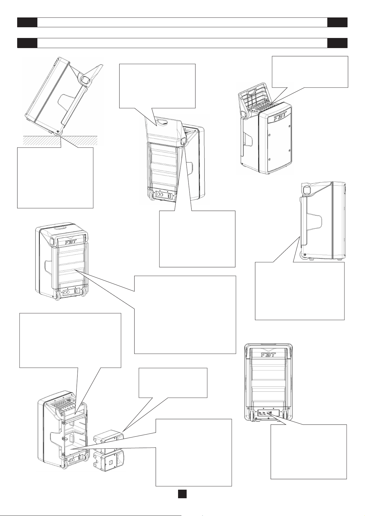
Coperchio / maniglia
a meccanismo basculante
Fold-away cover / handle
Couvercle / poignée à mécanisme
Deckel / Griff mit Kippmechanismus
basculant
Manopole multifunzione per
blocco/sblocco e asportazione del
coperchio-maniglia
Multifunction knobs to lock/release
or completely remove the cover-handle
Boutons multifonctions pour le
blocage/déblocage et l’enlèvement du
couvercle-poignée
Multifunktions-Drehgriffe für
Verriegelung/Freigabe und Abnahme
des Deckels-Griffs
Tutti i componenti integrati al’interno sono precablati,
pronti all’uso senza ulteriori collegamenti
per un utilizzo “ user friendly “
All the integrated internal components are
prewired and ready for use, without requiring any
additional connections for truly
user-friendly operation
Tous les composants incorporés à l’intérieur sont
précâblés, prêts à l’emploi sans aucun autre
branchement pour une utilisation “conviviale”
Alle inneren Bauteile sind vorverkabelt und
für einen bedienerfreundlichen Gebrauch
ohne weitere Anschlüsse einsatzbereit
ALLGEMEINEMERKMALE
Mixer audio integrato nella struttura
Fully-integrated mixer
Mixeur audio intégré dans la structure
In Struktur integrierter Audio Mixer
Pannello posteriore rimovibile per bloccare
e proteggere i satelliti nelle proprie sedi
their storage spaces during transportation
Panneau arrière amovible pour bloquer et
protéger les satellites dans leurs logements
durante il trasporto
Removable rear panel to protect and
immobilise the satellite speakers in
pendant le transport
Abnehmbare rückseitige Platte
zum Befestigen und Schutz der
Satelliten während der Transports
DF
Coppia di diffusori passivi a 2 vie
A pair of two-way passive cabinets
Paire de diffuseurs passifs à 2 voies
Zwei passive 2-Wege Lautsprecher
Vano di contenimento satelliti con guide
di centraggio per evitare anche il più
piccolo spostamento
Satellites storage space with locating
guide to prevent even the smallest
Logement des satellites avec guides
de centrage pour éviter le moindre
Aufnahmefach der Satelliten mit
Zentrierführung zur Vermeidung
auch der geringsten Verstellung
movements
déplacement
4
3 amplificatori audio di potenza
forniscono il segnale al Sub-woofer
3 amplificateurs sonores de puissance
fournissent le signal au Sub-woofer et
3 Audio-Leistungsverstärker liefern
dem Sub-woofer und den 2 satelliten
ed ai 2 satelliti
3 power amplifiers driving the
sub-woofer and 2 satellites
aux 2 satellites
das Signal
Page 7
COPERCHIO / MANIGLIA
COVER / HANDLE
UKI
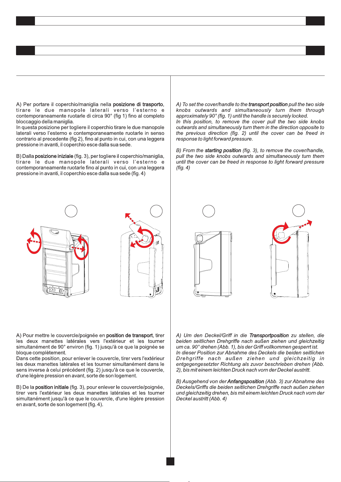
ISTRUZIONI PER APRIRE ( POSIZIONE DI TRASPORTO )
E TOGLIERE IL COPERCHIO/MANIGLIA
COUVERCLE / POIGNÉE
INSTRUCTIONS POUR OUVRIR ( POSITION DE TRANSPORT )
ET ENLEVER LE COUVERCLE/POIGNÉE
INSTRUCTIONS FOR OPENING ( TRANSPORT POSITION )
AND REMOVING THE COVER/HANDLE
DECKEL / GRIFF
ANLEITUNGEN ZUM ÖFFNEN ( TRANSPORTPOSITION )
UND ABNEHMEN DES DECKELS/GRIFFS
DF
1 2
3
4
5
Page 8
I
CARATTERISTICHE GENERALI
GENERAL FEATURES
UK
AMICO 10 SAT
F
CARACTÉRISTIQUES GÉNÉRALES
Adattatore per supporto a muro orizzontale
Adapter for horizontal wall support
Adaptateur pour support à mur horizontal
Adapter für waagerechte wandbefestigung
ALLGEMEINEMERKMALE
D
Maniglia integrata
Built-in handle
Poignée intégrée
Integrierter tragegriff
Adattatore integrato per stativo
Built-in adapter for stand mounting
Adaptateur intégré pour statif
Integrierter adapter für stativ
CAUTION
|
|
RISK OF ELECTRIC SHOCK
|
<
DO NOT OPEN
L R
OUTPUTS
SUB
SAT
LIMIT
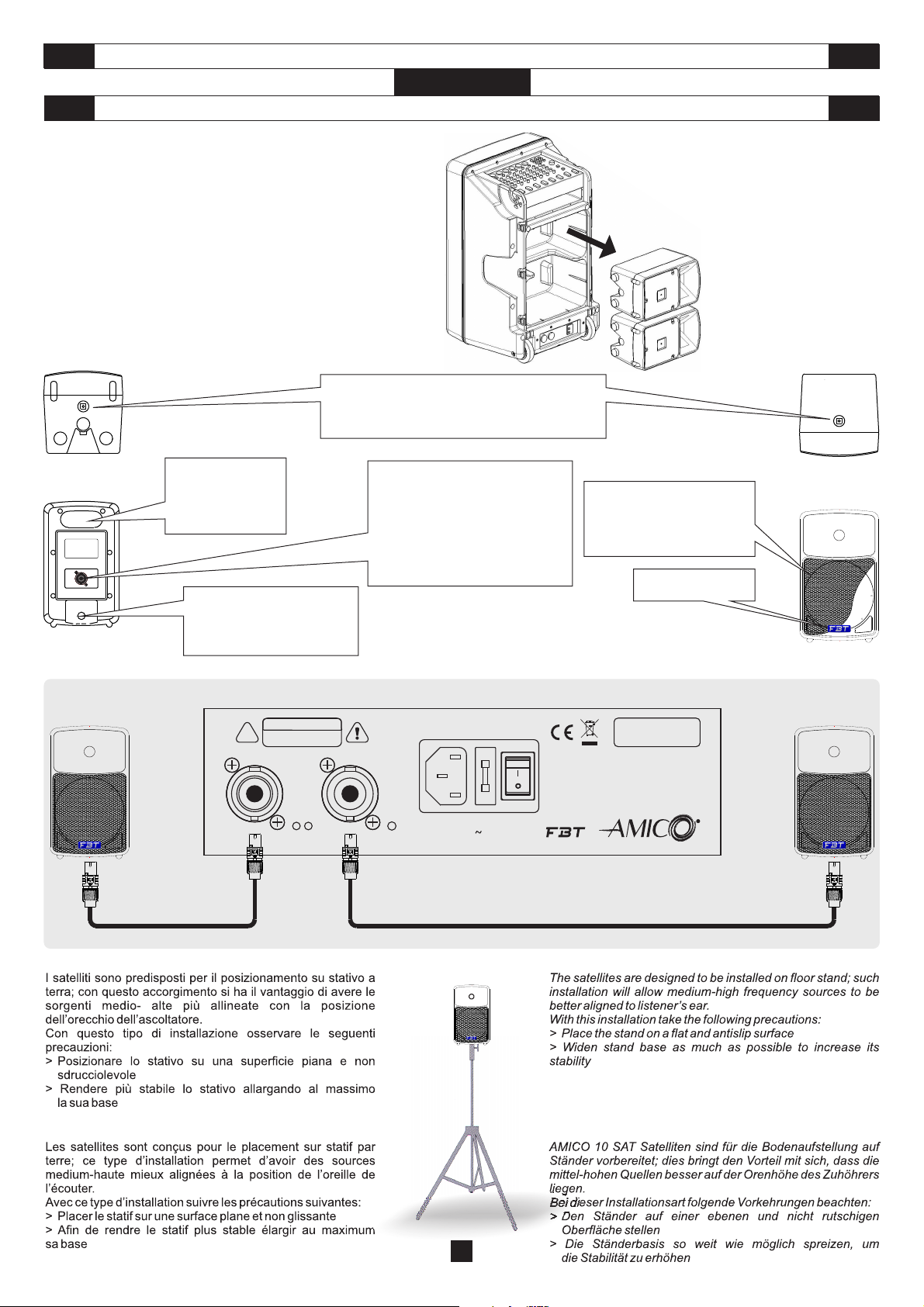
Ingresso Speakon per il collegamento
all’amplificatore del sistema
Speakon connector input for connection
to the system amplifier
Entrée speakon pour le raccordement
du système à l’amplificateur du système
Speakon-Eingang für den Anschluss
an den Verstärker des Systems
220/230 V 50/60Hz
PRT
T 5 AL - 250V
Griglia metallica di protezione
Protective metal grille
Grillage métallique de protection
Metallschutzgitter
FBT logo
BUILT-IN AMP:
FREQ. RANGE:
MAX SPL (cont./peak):
POWER CONSUMPTION: 800 VA
MADE IN ITALY
500W + 2 x 150W
40 Hz - 20 kHz
124/130 dB
10USB
R
6
Page 9
DIMENSIONI
DIMENSIONS
UKI
DIMENSIONS
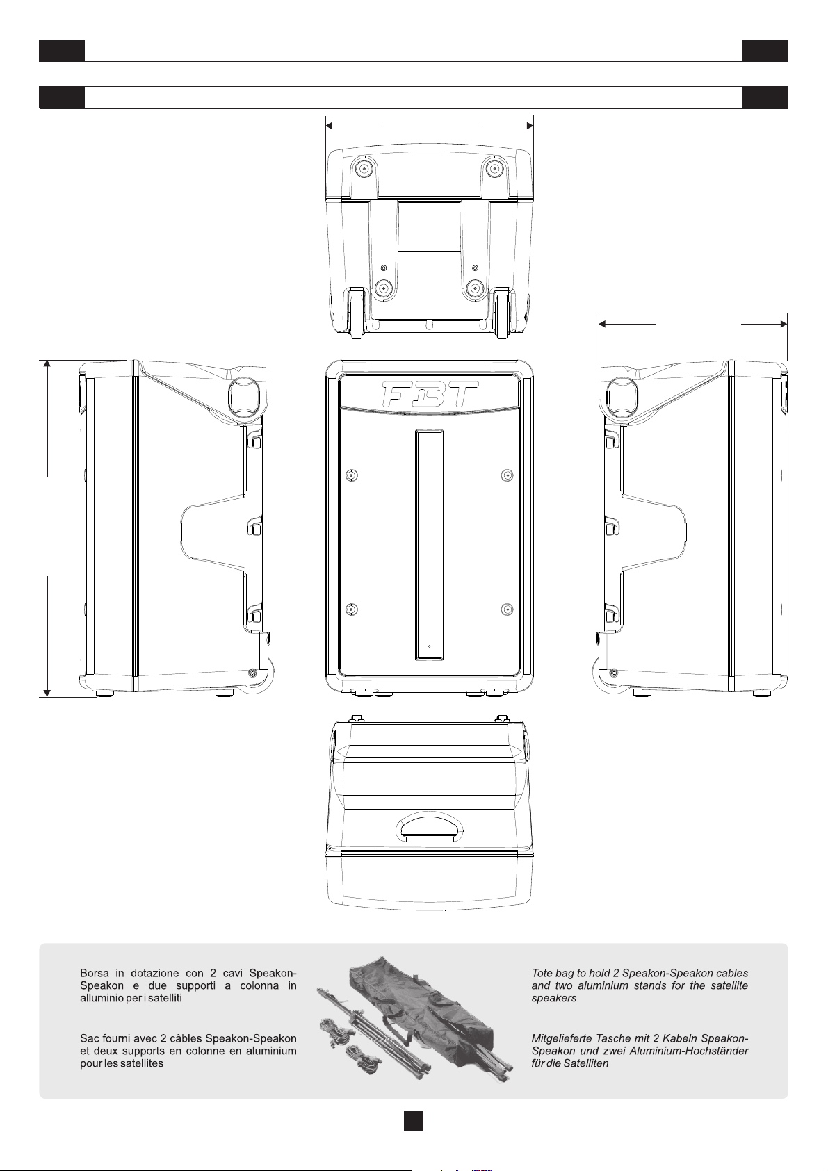
478mm / 18.8inch
ABMESSUNGEN
433mm / 17inch
DF
780mm / 30.7inch
ACCESSORI IN DOTAZIONE SUPPLIED ACCESSORIES
ACCESSOIRES FOURNIS LIEFERUMFANG
7
Page 10
CONNETTORI
CONNECTORS
UKI
maschio
male
femmina
female
schema
diagram
CONNESSIONE DI USCITA STEREO CONNESSIONE DI USCITA BRIDGE
STEREO OUT CONNECTION BRIDGE OUT CONNECTION
USCITA POSITIVA
POSITIVE OUT
USCITA NEGATIVA
NEGATIVE OUT
AL DIFFUSORE
TO SPKR
USCITA POSITIVA
POSITIVE OUT
AL DIFFUSORE
TO SPKR
USCITA NEGATIVA
NEGATIVE OUT
stereo
mono
schema
diagram
schema
diagram
RCA PHONO JACKS
BASE
PUNTA
TIP
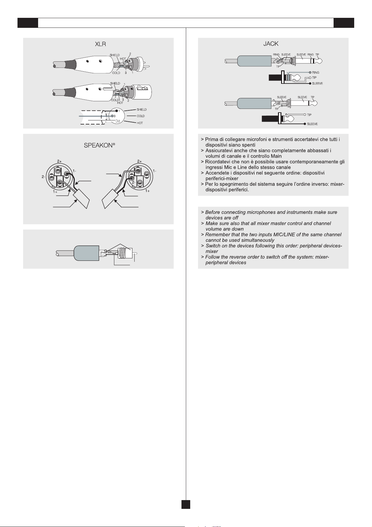
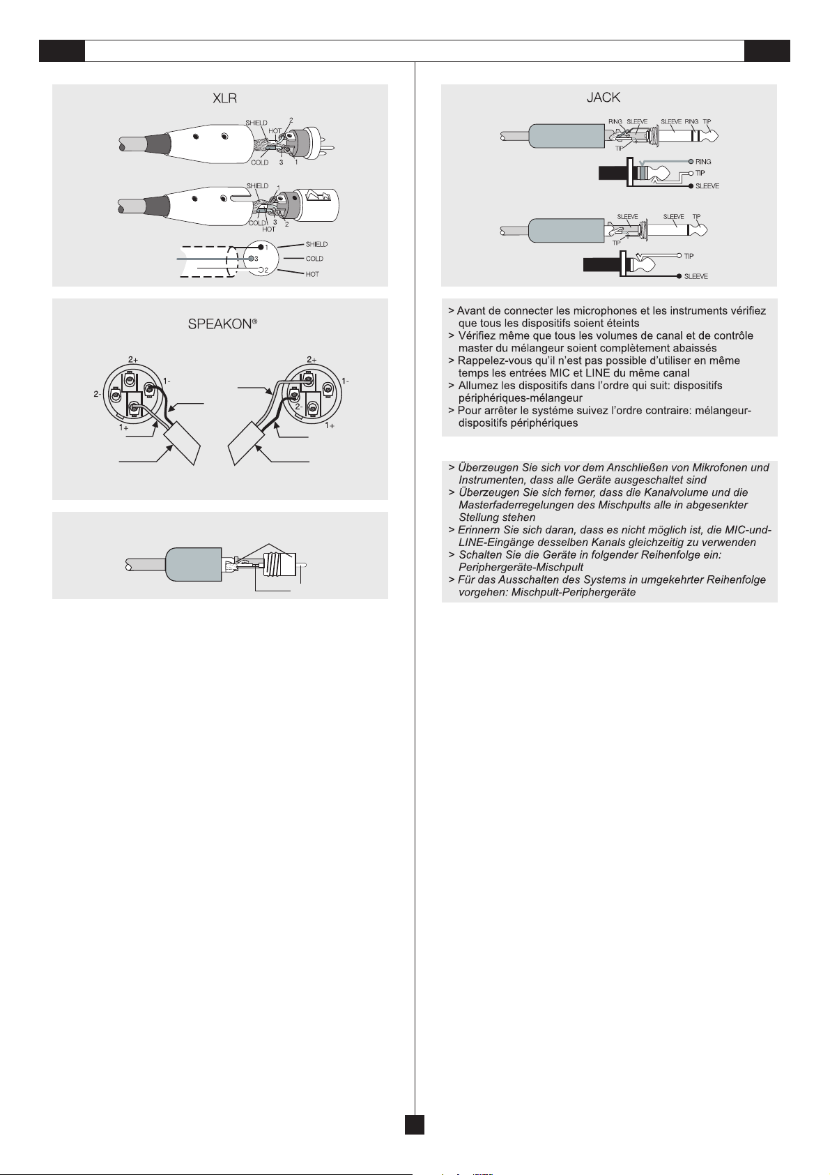
I connettori sono “femmine” peri dispositivi di ingressoe“maschi” per i
segnali di uscita; infatti i cavi di collegamento XLR-XLR usati ad esempio
per collegare un microfono ad un mixer, sono sempre maschio da un lato e
femmina dall’altro.
Hanno tre polievengonoutilizzati quasi sempre percondurresegnali mono
bilanciati; itre poli della XLR corrispondonorispettivamente alla massa (1),
al segnale positivo (2) e al segnale negativo (3). L’uso più comune dei
Cannon è quello di collegare microfoni a mixer o preamplificatori, oppure
quello relativo alle uscite bilanciatediunmixercollegate a casse e monitor.
Jack
I sono connettori tipici per trasportare due segnali separati di due
canali, destro e sinistro,conununico connettore e quindi possono esseredi
tipo mono o stereo.
I Jack mono (TS) detti anche sbilanciati si differenziano da quelli stereo
(TRS) obilanciati per la loro struttura. I primi hanno lo spinotto diviso indue
parti, punta e massa ( Tip e Sleeve ), alle quali sono collegati i due poli:
rispettivamente il segnale vero e proprio tramite il filo interno alla maglia
(polo positivo) e la terra localizzata a livello della maglia schermante
metallica sottostante il rivestimento protettivodigomma.
I Jack stereo o bilanciati sono divisi in tre parti in quanto hanno un anello
centrale chiamato Ring collegato ad un secondo filo che costituisce il terzo
polo (negativo). In questo caso, convenzionalmente per i segnali bilanciati
si faviaggiare il canalesinistro sulla punta e quello destro sull’anello. IJack
stereo spesso vengono utilizzati in alternativa a quelli mono per trasferire
un segnale, per l’appuntomono, ma bilanciato, ovvero per la produzione di
un segnale audio privo di interferenze o ronzii di massa, e quindi più fedele
possibile a quello di origine.
I collegamentibilanciati sono consigliatisoprattutto quando icavi iniziano a
superare i tre metri, poiché il fattore lunghezza è proporzionale alla
possibilità di ricevere interferenze e,quindi,di“sporcare”il segnale.
XLR
connectors are “female” for input devices and “male” for output
XLR
signals. As a matter of fact, the XLR-XLR connecting cables used, for
instance, to connect a microphone to a mixer always have a female socket
at one end and amaleplugatthe other end.
They are three-pole connectors often used to transmit balanced mono
signals. XLR three poles correspond to ground (1), positive signal (2) and
negative signal (3) respectively. Generally, Cannon are used to connect
microphones to mixers or preamplifiers; otherwise, they are often used to
connect the balanced outputs ofamixertoloudspeakers and monitors.
are the typical connectors used for transmitting two separatesignals
Jacks
of two channels -right and left- by means of a single connector and, thus,
they can be mono orstereo.
Mono (TS) Jack connectors -also called unbalanced- differ from stereo
(TRS) jack connectors–also called balanced- intheir structure. Mono jack
plugs are divided into two parts, Tip and Sleeve, to which the two poles are
connected: the two poles are, respectively, the real signal, throughthe wire
of the mesh (positive pole), and the earth, located at the level of the metal
shielding mesh beneath the rubberprotectivecoating.
Stereo or balanced Jack connectors are divided into three parts since they
feature a central Ring connected to a second wire, which is the third pole
(negative pole). Inthis case, conventionally,as for balanced signals,the left
channel travels over the tip and the right one over the ring. Stereo Jack
connectors are often used instead of the mono ones when a mono
balanced signal shall be transmitted, i. e. in order to generate an audio
signal without earth hum and interference and, thus, as faithful to the
original as possible.
Balanced connections are recommended mainly if cables are longer than
three meters since the length is proportional to the possibility of
interferences and, therefore, it couldaffectsignal“cleanliness”.
Gli non possono esserebilanciati poiché hannosolo due poli: segnale
RCA
(punta centrale) e massa (margine circolare), e sono quindi connettori
mono sbilanciati.
Questo tipo di connettori, quasi sempre in coppia, si utilizzano soprattutto
per segnali stereo di apparecchiatureHI-FI,qualilettoriCD, giradischi, ecc.
SPEAKON è un connettore adatto appositamente per il collegamento tra
finali di potenza e altoparlanti; inserendolo nell’apposita presa si blocca in
modo da impedire un distacco accidentale; inoltre è dotato di protezione
contro scosse elettriche e garantisceunacorrettapolarizzazione.
connectors cannot be balanced since theyonly have two poles:signal
RCA
(centre pin) and ground (outer ring). Therefore, they are unbalanced mono
connectors.
This type of connectors, often paired, are mainly usedfor the stereosignals
of hi-fi devices such asCDorrecordplayer,etc.
SPEAKON
is a connector which is specially adapted for connecting power
terminals to loudspeakers; when inserted in an appropriate socket it locks
so as to prevent accidental disconnection; moreover it is equipped with
protection against electrical shocks and guarantees the correct
polarisation.
8
Page 11
CONNECTEURS
ANSCHLÜSSE
DF
male
female
diagram
STEREO OUT CONNECTION BRIDGE OUT CONNECTION
POSITIVE OUT
NEGATIVE OUT
POSITIVE OUT NEGATIVE OUT
TO SPKR TO SPKR
stereo
diagram
mono
diagram
RCA PHONO JACKS
BASE
PUNTA
TIP
Les connecteurs sont des« femelles »pour les dispositifsd'entrée et des«
mâles » pour les signaux de sortie ;en effet, les câbles de connexion XLR-XLR,
utilisés par exemple pour connecter un microphone à un mélangeur, sont
toujours mâle d'un côté et femelle de l'autre.
Ils ont trois pôles et sont utilisés presque toujours pour conduire des signaux
mono-balancés ; les trois pôles de la XLR correspondent respectivement à la
masse (1), au signal positif (2) et au signal négatif (3). L'usage le plus commun
des Cannon est celui de connecter les microphones au mélangeur ou aux
préamplificateurs, ou celui concernant les sorties balancées d'un mélangeur
connectées aux enceintes et aux moniteurs.
Les sont desconnecteurs typiques pour transporterdes signaux séparés
Jacks
de deux canaux, droit et gauche, avec un seul connecteur et donc ils peuvent
être de type mono ou stéréo.
Les Jacks mono (TS), connus aussi comme non-balancés, se différencient de
ceux stéréo (TRS)oubalancéspour leur structure. Lesjacksmonoont la broche
divisée en deux parties, pointe et corps (Tip et Sleeve), auxquelles sont
connectés les deuxpôles:respectivement le véritable signal parlefilinterne à la
maille (pôlepositif)et la terre situéeau niveau de lamailleprotégeant métallique
sous-jacent au gainage protecteur en caoutchouc.
Les Jacks stéréo ou balancés sont divisés en trois parties puisqu'ils ont un
anneau central, dit Ring, relié à un deuxième fil qui représente le troisième pôle
(négatif). En ce cas, conventionnellement, pour les signaux balancés on fait
voyager le canal gauche sur la pointe et le canal droit sur l'anneau. Les Jacks
stéréo sont souvent utilisés à la place des mono pour transférer un signal,
précisément mono, mais balancé, ou pour la production d'un signal audio sans
interférences ou bourdonnements de masse, et donc plus le fidèle possible à
celui d'origine.
Les branchements balancés sont conseillés surtout lorsque les câbles
dépassent les trois mètres de long, car la longueur est proportionnelle à la
possibilité de recevoir des interférences et, donc, de « salir »le signal.
Les connecteurs nepeuvent pas être balancéscar ils n'ontque deux pôles
: signal (pointe centrale) et masse (marge circulaire) et ce sont donc des
connecteurs mono non-balancés.
Ce genre de connecteurs, presque toujours couplés, est utilisé surtout pour les
signaux stéréo des appareils hi-fi, comme les lecteurs de CD, les tournedisques, etc.
Le connecteur a été spécialement conçu pour le branchement des
terminaux de puissance et des hauts-parleurs. Placé dans la prise adéquate il
sert à prévenirun débranchement accidentel. Deplusil est pourvu d’unsystème
de protection contre les secousses électriques et garantit un niveau de
polarisation correct.
XLR
RCA
SPEAKON
Die -Steckverbinder sind für Eingangsgeräte „weiblich“ und für
XLR
Ausgangssignale „männlich“; tatsächlich sind die beispielsweise für den
Anschluss eines Mikrofons an einen Mixer verwendeten Kabel stets auf einer
Seite männlich und auf der anderen weiblich.
Sie sind dreipolig und werden meist für die symmetrische Signalübertragung
verwendet. Die drei XLR-Pole entsprechen der Masse(1), dem positiven Signal
(2) und dem negativen Signal (3). Die Cannon-Steckverbinder werden generell
für das Anschließen von Mikrofonen an Mischpulte oder Vorverstärker
verwendet oder aber auch für den Anschluss von symmetrisierten Ausgängen
eines Mischpults an Lautsprecherboxen und Bildschirmen.
, zu Deutsch Klinkenstecker, sind typische Steckverbinder, die mit einem
Jacks
einzigen Stecker zwei separate Signale von zwei Kanälen, einem rechten und
einem linken, übertragen und somit Mono oder Stereo sein können.
Die Mono-Stecker (TS), auch unsymmetrische Stecker, unterscheiden sich von
den Stereo- oder symmetrischen Steckern (TRS) durch ihre Struktur. Der Stift
der Mono-Stecker ist in zwei Teile unterteilt, Spitze und Schaft (Tip und Sleeve),
an die beide Pole angeschlossen sind. Dabei wird das eigentliche Signal über
den intern liegenden Leiter geführt (positiver Pol) und die Masse über die
metallischeAbschirmungunter der schützenden Gummiverkleidung.
Die Stereo- bzw.symmetrischenSteckersindindrei Teile unterteilt und verfügen
als dritten (negativen) Pol über einen mittleren, an einen zweiten Leiter
angeschlossenen Ring. In diesem Fall ist die Spitze gewöhnlich mit den
symmetrischen Signalen für den linken Kanal belegt und der Ring mit denen für
den rechten Kanal. Stereo-Stecker werden oft anstelle von Mono-Steckern
verwendet, wenn ein Mono-Signal symmetrisch übertragen oder wenn ein
Audio-Signal ohne Störungen oder Massebrummen, also so tongetreu wie nur
möglich, wiedergegeben werden soll.
Symmetrische Verbindungen sind vor allem bei Überschreiten von drei Meter
Kabellänge empfehlenswert, da der Längenfaktor proportional zur Möglichkeit
steht, dass das Signal Störungen empfängt und somit „verunreinigt“ wird.
-Stecker bzw. zu Deutsch Cinch-Stecker können nicht symmetrisch sein,
RCA
da sie nur zwei Pole haben, nämlich Signal (mittlere Spitze) und Masse (runder
Rand). Es sind also monosymmetrische Stecker.
Diese Art an Steckverbindern kommen meist paarweise für Stereosignale in
HiFi-Geräten, wie CD-Playern, Plattenspielern usw.zumEinsatz.
SPEAKON
ist ein Eingang der extra für die Verbindung zwischen
Leistungsenden und Lautsprechers angepasst wurde. Wenn er in die
entsprechende Buchse eingesteckt wird, dann blockiert er so, dass er nicht
ungewollt herausgezogen werden kann. Er ist außerdem mit einem
Stromschlagschutz ausgerüstet und gewährleistet die richtige Polarisation.
9
Page 12

ARTWORK
UKI
DF
0
High High High High
-15 +15
0
Mid Mid Mid Mid Mid Mid
-12 +12
0
Low Low Low Low Low Low
-15 +15
-15
Mon Mon Mon Mon Mon Mon
0
0
0
-15
Eff
0
0
0
mix
Pan Pan Bal Bal Bal Bal
L
R
0
dB
Gain Gain Gain Gain Gain Gain
6010
line
30-20
0
-15 +15dB0-15 +15dB0-15 +15dB0-15 +15dB0-15 +15dB
dB
dB
dB
dB
dB
mic
-12 +12
-15 +15
0
0
Eff
0
0
L
0
0
0
-15
0
dB
-15
dB
0
mix
R
dB
6010
line
30-20
dB
dB
mic
-12 +12
-15 +15
0
Eff
0
L
0
dB
0
0
R
6010 mic
-12 +12
dB
-15 +15
0
0
dB
Eff
0
0
dB
L
0
0
-15
0
-15
0
mix
0
dB
High
0
dB
0
dB
-15
0
dB
-15
dB
0
mix
R
dB
6010 mic
-12 +12
-15 +15
0
Eff
0
L
0
dB
0
dB
-15
0
0
dB
-15
0
dB
0
mix
R
0
dB
6010 mic
High
Eff
MONO MONO
-15
Vol Vol Vol Vol Vol Vol
-40
0
0
Mute Mute Mute Mute Mute Mute
Peak Peak Peak Peak Peak Peak
1
-15
-5
-40
0
dB
0
0
0
2
-15
-5
dB
-5
-40
0
0
0
3 / 4
-15
-5
-40
dB
0
dB
0
0
-15
-5
-40
0
0
0
5 / 6 7 / 8 9 / 10
dB
0
-12 +12
0
-15 +15
-15
0
0
-15
0
0
mix
L
0
dB
STEREOSTEREOSTEREOSTEREO
-15
-40
0
0
0
0
R
6010 mic
0
Program Chart
Small Hall
00-02
Mid Hall
03-05
Big Hall
06-07
Church
08-09
Small Room
10-12
Mid Room
13-15
Big Room
16-18
Cathedral
19
Plate
20-26
Spring
27-29
Gated Rev.
30-35
dB
Reverse
36-39
Early Refl.
40-43
44-47
Ambience
48-49
Stadium
50-58
Delay
99
Effects
dB
Mon
dB
Eff
Snd
dB
Pgm
Press
to
sel.
59
60-65
66-69
70-73
74-79
Chorus & Rev
80-81
Flanger & Rev.
82-83
84-85
Pitcher & Rev
86-87
Pitch & Rev.
88-89
90
Delay & Gated
91
Delay & Reverse
92-93
Delay & Chorus
94-95
Delay & Flanger
96-97
Delay & Phaser
98-99
Delay & Pitch
Digital Processor
-15
0
0
0
-15
0
0
0
88
Echo
Chorus
Flanger
Phaser
Pitch Shift
Delay & Re
dB
dB
10 USB
Integrated Sound System
Phantom
Mon
0
0
USB/Tape
to Main
USB
Tape
0
0
-15
0
dB
-15
0
dB
Sub
Bal.
On
6
0dB
-5
-10
0
-12
0
L
R
Pwr
RightLeft
8
dB
R
Tap
-15
Vol
-5
dB
-5
-40
0
0
0
dB
-15
-5
-40
0
0
0
Main
0
dB
5
0
0
dB
10
Mute
Peak
EFFECT
MASTER
SEZIONE MONO
MONO SECTION
PARTIE MONO
SEKTION MONO
SEZIONE STEREO
STEREO SECTION
PARTIE STÉRÉO
SEKTION STEREO
Line
1
2
L3
mono
L5
R
mono
4
L7
R
mono
6
R
8
Mic Mic Mic Mic Mic Mic
MONO STEREO STEREO STEREO STEREO
1 2
3
|
|
|
<
RISK OF ELECTRIC SHOCK
5 6
4
CAUTION
DO NOT OPEN
7
8
OUTPUTS
SUB
SAT
220/230 V 50/60Hz
LIMIT
L R
PRT
T 5 AL - 250V
SEZIONE EFFETTO
EFFECT SECTION
PARTIE EFFECT
SEKTION EFFEKT
L9
mono
9 10
O
EFF.
R
Send
10
L
Return
R
BUILT-IN AMP:
FREQ. RANGE:
MAX SPL (cont./peak):
POWER CONSUMPTION: 800 VA
MADE IN ITALY
Mon.
Foot Sw.
500W + 2 x 150W
40 Hz - 20 kHz
124/130 dB
10USB
SEZIONE MASTER
MASTER SECTION
PARTIE MASTER
SEKTION MASTER
CD/TapeOut
L
USB
R
R
Tape In
L
R
MAIN
SEZIONE ALIMENTAZIONE E POTENZA
SECTION ALIMENTATION ET PUISSANCE
10
SUPPLYAND POWER SECTION
VERSORGUNG UND LEISTUNGSSEKTION
Page 13

I
CONTROLLI & FUNZIONI
SEZIONE MONO_________________________________
High / Mid / Low:
acuta, media e bassa dei segnali. Con la manopola in posizione
centrale (0) non viene effettuata alcuna alterazione timbrica;
ruotando la manopola in senso antiorario si ottiene una graduale
attenuazione delle frequenze, in senso orario si ottiene la loro
esaltazione.
regola il livello di segnale del canale da inviare all’uscita jack
Mon:
«MON». La regolazionerisente dell’azione deicontrolli di tonoed è
indipendente dal controllo delvolume.
consente di inviareal processore digitale dieffettiil segnale del
Eff:
canale, dipendente dalcontrollo del volume;in tal modoè possibile
aggiungere una componente dieffettoregolabile per ogni canale.
regola la posizione del suono nel fronte stereofonico,
Pan:
consentendo di variare in continuità l’immagine stereo. Lo
spostamento della manopola verso sx. o verso dx. varia le
proporzioni dei due segnali fino ad ottenere, nelle posizioni
estreme, l’annullamento di unodei due.
regola la preamplificazione del segnale proveniente dagli
Gain:
ingressi XLR e Jack, ottimizzandola al corretto funzionamento dei
circuiti di ingresso. Per ottenere il bilanciamento ottimale fra il
rapporto S/N e la gamma dinamica regolare il livello in modo tale
che il led PEAK si accenda occasionalmente solo in presenza di
picchi di segnale. La scala da 10 a60 indica illivello di regolazione
dell’ingresso MIC; da -20 a 30 indica il livello di regolazione
dell’ingresso LINE.
regola il livello del segnale di canale da inviare ai controlli
Vol:
generali; normalmente le migliori prestazioni della circuiteria di
canale si ottengono con la manopola posizionate a circa 3/4 della
sua corsa e con il GAIN regolato in modo da ottenere il livello
desiderato.
permette di attivare/disattivare ilcanale.
Mute:
l’accensione di questo led indica che il livello del segnale
Peak:
all’uscita dei controlli di tono è prossimo alla saturazione: si
consiglia di agire sulcontrollo del GAIN.
controlli di tono per la regolazione della gamma
SEZIONE STEREO______________________________
Vol:
regola il livello del segnale di canale da inviare ai controlli
generali; normalmente le migliori prestazioni della circuiteria di
canale si ottengono con la manopola posizionate a circa 3/4 della
sua corsa e con il GAIN regolato in modo da ottenere il livello
desiderato.
Mute:
permette di attivare/disattivare ilcanale.
Peak:
l’accensione di questo led indica che il livello del segnale
all’uscita dei controlli di tono è prossimo alla saturazione: si
consiglia di agire sulcontrollo del GAIN.
PANNELLO POSTERIORE
Mic:
presa di ingresso per connettore XLR bilanciata
elettronicamente, consente di collegare sorgenti di segnale a
basso livello, come microfonia bassa impedenza.
L-mono-R:
stereo; consentono di collegare al mixer sorgenti monofoniche
(utilizzando solo la presa L-mono), o stereofoniche (utilizzando
entrambe le prese).
Le sorgenti STEREO come ad esempio un lettore CD, una
tastiera ecc., sono composte da un canale sinistro e da un
destro che, necessariamente, debbono essere controllate da
comandi che consentano regolazioni su entrambi i segnali
contemporaneamente.
Ecco allora l’opportunità di inserire dei canali di ingresso
stereo
unificandone i controlli.
I canali stereohanno, al posto del controllo di PAN,un controllo
di bilanciamento (BAL) che consente di compensare eventuali
differenze di livello fraisegnali dei due canali.
prese di ingresso bilanciate per connettore a jack
che, in pratica,riuniscono due canali mono
PANNELLO POSTERIORE
presa di ingresso per connettore XLR bilanciata
Mic:
elettronicamente, consente di collegare sorgenti di segnale a
basso livello, come microfonia bassa impedenza.
prese di ingresso per connettore a jack ; bilanciate
Line:
elettronicamente consentono di collegare sorgenti di segnale ad
alto livello, come tastiere, chitarre elettriche, ecc.; è possibile
utilizzare anche connettori mono: questo determina lo
sbilanciamento automatico del segnale.
SEZIONE STEREO______________________________
High / Mid / Low:
acuta, media e bassa dei segnali. Con la manopola in posizione
centrale (0) non viene effettuata alcuna alterazione timbrica;
ruotando la manopola in senso antiorario si ottiene una graduale
attenuazione delle frequenze, in senso orario si ottiene la loro
esaltazione.
regola il livello di segnale del canale da inviare all’uscita jack
Mon:
«MON». La regolazionerisente dell’azione deicontrolli di tonoed è
indipendente dal controllo delvolume.
consente di inviareal processore digitale dieffettiil segnale del
Eff:
canale, dipendente dalcontrollo del volume;in tal modoè possibile
aggiungere una componente dieffettoregolabile per ogni canale.
regola la posizione del suono nel fronte stereofonico,
Bal:
consentendo di variare in continuità l’immagine stereo. Lo
spostamento della manopola verso sx. o verso dx. varia le
proporzioni dei due segnali fino ad ottenere, nelle posizioni
estreme, l’annullamento di unodei due.
regola la preamplificazione del segnale proveniente dagli
Gain:
ingressi XLR e Jack, ottimizzandola al corretto funzionamento dei
circuiti di ingresso. Per ottenere il bilanciamento ottimale fra il
rapporto S/N e la gamma dinamica regolare il livello in modo tale
che il led PEAK si accenda occasionalmente solo in presenza di
picchi di segnale.
controlli di tono per la regolazione della gamma
11
0
High High High
-15 +15
0
Mid Mid Mid
-12 +12
0
Low Low Low
-15 +15
-15
Mon Mon Mon
0
0
-15
Eff
0
0
mix
Pan Pan Bal
L
0
dB
Gain Gain Gain
MONO MONO
-15
Vol Vol Vol
-40
0
0
Mute Mute Mute
Peak Peak Peak
1
1
Mic Mic Mic
0
dB
-15 +15dB0-15 +15dB
0
-12 +12
-15 +15
0
0
Eff
0
0
L
0
-40
0
0
dB
0
dB
-15
0
dB
-15
dB
0
mix
R
dB
6010
mic
line
30-20
-15
-5
0
dB
dB
dB
0
dB
dB
0
R
6010
mic
line
30-20
-5
0
dB
2
Line
2
MONO STEREO
1 2
Eff
-12 +12
-15 +15
-15
0
0
-15
0
0
mix
L
0
dB
STEREO
-15
-40
0
0
3 / 4
mono
3
0
dB
0
dB
0
dB
dB
0
R
6010 mic
-5
0
dB
L3
R
4
4
Page 14

I
CONTROLLI & FUNZIONI
SEZIONE EFFETTI_______________________________
AMICO 10 USB è dotato di una sezione effetti con processore digitale di segnali audio in grado
di simulare le sonorità di qualsiasi ambiente acustico. 99 differenti effetti consentono di
aggiungere particolari sonorità aisegnali diretti che transitanosuicanali del mixer.
regola la quantità disegnale di ritorno dall’effetto da inviare all’uscitajack MON.
Mon:
Eff Snd:
dell’effetto di ritorno.
Pgm:
il selettore «PRESS TO SEL».
Tap:
l’ultima impostazione rimane memorizzataal momento dello spegnimentodelsistema.
Vol:
Mute:
Peak:
dell’effetto è di pocoinferioreal punto di saturazione.
PANNELLO POSTERIORE
Send / Return:
mandata effetto da collegare all’ingresso dell’effetto esterno; il livello è
regolato dal potenziometro EFFSEND.
Le prese jack RETURN L/R consentono di collegare al mixer l’uscita
dell’effetto esterno escludendo, contemporaneamente, l’effetto
interno.
Foot SW.:
distanza che attiva/disattiva l’effettointerno.
controlla il livello generale del segnale da inviare all’uscita jack SEND e all’ingresso
il display mostra il numero del programmascelto; per selezionare e confermareutilizzare
il pulsante TAP definisce il tempo di ripetizione desiderato, secondo il ritmo musicale;
controllo di volume dell’effettoinviatoalle uscite MAIN L/R.
permette di attivare/disattivare ilcanale.
il led PEAK rileva il livello di picco del segnale e si accende quando il segnale di uscita
nella presa jack SEND è presente il segnale della
presa jack mono per la connessione di un comando a
SMALL HALL/MIDHALL/BIGHALL
I programmi HALL rappresentano la vera emulazione delle grandi sale da
concerto, dove i musicisti sono disposti sul palco al centro di un grande
ambiente acusticamente riflettente. Gli HALL consentono di fondere in un
mix omogeneo i vari strumenti provenienti dai singoli canali, creando
intorno a loro un ambiente estremamente reale. Questi programmi
risultano ottimi per voci singole, cori e strumenti acustici.
CHURCH
Riverbero in una chiesa con molte seconde riflessioni.
ROOM
I programmi ROOM ricostruiscono l’ambiente delle sale acustiche da
concerto di media grandezza, caratterizzate da particolari colorazioni
dovute alle pareti riflettenti in grado di innescare un gran numero di
riflessioni. Si tratta di ambienti di tipo «music club», salotti e sale prova,
dove l’alone di effetto decade abbastanza rapidamente mantenendo
buona la chiarezza e l’intelligibilità del segnale originale. I programmi
ROOM sono particolarmente adatti ad applicazioni cinematografiche,
televisive, strumenti ritmici e di accompagnamento.
CATHEDRAL
Riverbero stretto e lungo di una grossa cattedrale, adatto per assoli
strumentali o voci di brani lenti.
PLATE
Il riverbero PLATE veniva originariamente ottenuto con un sottile foglio di
metallo sospeso su molle e che veniva messo in vibrazione da un
trasduttore modulato dal segnale audio. Il risultato sul suono trasmesso
attraverso il PLATE era che provenisse da un grande spazio aperto. I
programmi di PLATE sintetizzano il suono di lastre di metallo con alta
diffusione iniziale ed un suono relativamente brillante e colorato. Questi
programmi sono pensati per essere utilizzati come parte della musica,
ammorbidendo ed addensando il suono originale; sono una scelta molto
comune soprattutto nella musica pop ed in particolare nelle percussioni.
SPRING
Simula la riverberazione classica di una molla.
GATEDREV.
Questo effetto, che rappresenta un riverbero tagliato artificialmente, è
divenuto famoso grazie al brano «in the air tonight» di PhilCollins.
REVERSE
Un riverbero nel quale la curva d’inviluppo è rovesciata, vale a dire che
inizialmente il volume è basso e poi aumenta.
EARLY REFL.
Questo riverbero è caratterizzato da prime riflessioni molto marcate e lo
predestinano a segnali dinamici ( batteria, percussioni, slap-bass, ecc. ).
AMBIENCE
Questo programma di riverberazione simula una stanza di media
grandezza senza successive riflessioni.
DELAY
Il DELAY è un effetto usato per modificare il suono di strumenti musicali
elettrici o amplificati. Viene anche talvolta chiamato, più impropriamente
«eco». La funzione generale del DELAY consiste nel registrare il suono in
ingresso e riprodurlo con un determinato ritardo temporale. Solitamente il
suono ritardato viene aggiunto al segnale originale anziché sostituirlo; in
tal caso l’effetto complessivo è simile a quello dell’eco.
ECHO
L’effetto ECHO produce elettronicamente dei ritardi a intervalli di tempo
regolari per suoni più spaziosi e profondi.
CHORUS
Questo effetto aggiunge al segnale originale una leggera variazione di
frequenza; così, in unione con una variazione degli alti, si produce un
piacevole effetto di sospensione. L’effetto CHORUS viene impiegato così
spesso in svariati modi nella diffusione dei segnali che ogni consiglio di
moderazione non sortirebbe alcun effetto. La velocità di modulazione va
da effetto CHORUS lento a veloce.
FLANGER
Il FLANGER è uneffetto musicaleelettronico realizzato mediante l’impiego
di una linea di ritardo, con tempi sensibilmente elevati, attraverso la quale
viene fatto passare il segnale da trattare. Il segnale così ritardato viene
miscelato col segnale originale, dando luogo alla cancellazione di quelle
frequenze che si trovano in opposizione di fase. Il suono così risultante
presenta picchi di risonanza e punti di assenza del segnale audio; l’effetto
sarà di evanescenzasull’interagamma dello spettro audio similealrumore
di un aereo a reazione che passa nelle vicinanze.
PHASER
Il PHASERlavora secondo il principio che al segnale audioviene aggiunto
un secondo segnale sfasato. Il materiale risulta così più spesso e
soprattutto più vitale. Questo effetto è stato utilizzato volentieri per le
canzoni con la chitarra e le superfici di tastiere, ma negli anni settanta è
stato anche introdotto intensivamente per altri strumenti come, ad
esempio, il piano elettronico.
PITCH SHIFT
Questo effetto ha la funzionedi produrre notesecondarie a quelle suonate
con una tonalità regolata dal musicista producendo delle armonie.
CHORUS & REV
Questo effetto combina il CHORUS con un riverbero, la cui lunghezza è
diversa a seconda del programma.
FLANGER & REV
La combinazione di effetto FLANGER e riverbero.
PITCH & REV
Con il PITCH SHIFTER si modifica leggermente la frequenza del segnale,
mentre il riverbero da un effetto spaziale.
DELAY & REV
DELAY e riverbero, la più frequente combinazione per canto, chitarre in
assolo, ecc.
DELAY & GATED
La combinazione di effetto ECHO e GATE per ottenere un suono corto e
«affilato» adatto per strumenti percussivi.
DELAY & CHORUS
Mentre il CHORUS contribuisce alla diffusione del segnale, con DELAY si
possono impostare interessanti effetti di ripetizione. Il canto, per esempio,
può essere dotato di un effetto accentuato senza chela voce suoni troppo
annegata.
DELAY & FLANGER
Effetto adatto per creare un suono canoro adeguato ai tempi, con un’aria
un pò «spacig».
DELAY & PHASER
Questo effetto pone in parallelo un DELAYmono eunPHASERmono.
DELAY & PITCH
Una ripetizione del segnale audio al quale viene aggiunto con il PITCH
SHIFTER un piacevole effetto di sospensione.
12
00-02
03-05
06-07
08-09
10-12
13-15
16-18
19
20-26
27-29
30-35
36-39
40-43
44-47
48-49
50-58
Program Chart
Small Hall
Mid Hall
Big Hall
Church
Small Room
Mid Room
Big Room
Cathedral
Spring
Gated Rev.
Reverse
Early Refl.
Ambience
Stadium
Delay
Plate
59.
60-65
66-69
70-73
74-79
80-81
82-83
84-85
86-87
88-89
90
91
92-93
94-95
96-97
98-99
Echo
Chorus
Flanger
Phaser
Pitch Shift
Chorus & Rev
Flanger & Rev.
Pitcher & Rev
Pitch & Rev.
Delay & Re
Delay & Gated
Delay & Reverse
Delay & Chorus
Delay & Flanger
Delay & Phaser
Delay & Pitch
Page 15

I
SEZIONE MASTER______________________________
CONTROLLI & FUNZIONI
Phan t om:
swit c h p e r l ’ atti v a zion e /dis a ttiva z i one
dell’alimentazione phantom negli ingressi microfonici MIC. La
maggior parte dei microfoni professionali a condensatore
richiedono l’alimentazione phantom, che è una bassa tensione
continua DC portata al connettore XLR del microfono. I microfoni
dinamici non richiedono l’alimentazionephantom.
visualizza l’accensione del sistema.
Pwr:
VU Meter:
visualizzazione emisura in decibel del livello di segnale
in uscita.
regola il livello generale dei segnali delle linee monitor
Mon:
provenienti dai canali di ingresso da inviare alle casse monitor del
sistema audio, collegate almixer tramite l’uscita jackMON.
regola il livello di ascolto del segnale proveniente
Sub:
dall’amplificatore interno del sistemaAMICO.
Balance:
regola la posizione del suono presente su tutti i segnali
provenienti dal sistema einviati alle uscite generaliMAINL/R.
regolazione del volume diascolto in cuffia.
USB / Tape to Main:
assegna l’ingressoTAPE IN e USB ( segnale
audio dal PC) alMAIN.
USB Tape:
Main:
regola il livello dell’ingressoTAPE IN e USB.
regola il livellogenerale di ascolto ditutti i segnali provenienti
dai canali mono,stereo e dalla sezioneeffetto, inviandoli alle uscite
jack MAIN L/R.
10 USB
Integrated Sound System
Phantom
-15
Mon
0
0
0
dB
USB/Tape
to Main
USB
Tape
0
0
-40
0
0
-15
0
dB
-15
-5
0
dB
Sub
Balance
Main
Left
R
Pwr
6
0dB
-5
-10
Right
0
8
-12
dB
0
L
R
0
dB
5
0
0
10
PANNELLO POSTERIORE
Mon:
uscita jack stereo bilanciata per collegare monitor o
subwoofers.
CD/Tape Out - Tape In:
prese per connettori pin jack RCA:
consentono di collegare al mixer apparecchi di registrazione audio
di tipo HI-FI stereo. CD/TAPE IN: prese di ingresso per collegare le
uscite di qualsiasi sorgente stereo in riproduzione ( registratore,
lettore CD, ecc. ). CD/TAPE OUT: prese di uscita per collegare
apparecchi stereo in registrazione.
COLLEGAMENTO DI UN REGISTRATORE STEREO
LINE IN
LINE OUT
Main L/R: prese jack stereo bilanciate di uscita; forniscono la
miscelazione dei segnali controllatidal comando MAIN.
MASTER
L
R
L
Mon.
R
CD/Tape Out
L
Tape In
USB
L
R
R
MAIN
13
Page 16

I
Il mixer AMICO è dotato di una porta USB alla quale è possibile
collegare un computer; laconnessione USB permette discambiare
audio di qualità CD fra il computer e il mixer. Questa caratteristica
permette di usare AMICO 10 USB come una flessibile soundcard
esterna. Per registrare e riascoltare dal computer con qualità CD è
possibile usare sia il registratore del sistema operativo o meglio
ancora usare un software DAW ( Digital Audio Workstation )
dedicato.
TRASMISSIONE E RICEZIONE DATI AUDIO
La porta USB invia i segnali LEFT e RIGHT del MAIN al computer.
La porta USB riceve un segnale audio stereo dal computer lo
assegna agli ingressi LEFTeRIGHT del canale TAPEIN del mixer.
PRECAUZIONI
Per assicurare che AMICO 10USBsia riconosciuto correttamente
dal computer, accendere sempre il mixer prima di inserire il cavo
USB nel computer.Allo spegnimento, spegnere primailcomputer e
attendere che il computer abbia completato lo spegnimento (shut
down), quindi spegnere ilmixer.
ISTRUZIONI PER LA CONNESSIONE DI WINDOWS
Nel momento in cui AMICO 10USB viene collegato alla porta USB
del computer, Windows automaticamente riconosce il sistema e
procede all’installazione dei driver«USB audio codec».
Dopo che AMICO 10USB è stato riconosciuto e i suoi driver
installati, aprire il PANNELLO DI CONTROLLO; scegliere SUONI,
VOCE e PERIFERICHE AUDIO; quindi scegliere SUONI e
PERIFERICHE AUDIO, selezionare AUDIO e selezionare «USB
audio codec» come dispositivo predefinito per la riproduzione e la
registrazione di suoni.
INTERFACCIA USB
1
IMPOSTARE AMICO 10USB PERLARIPRODUZIONEDALPC
Mentre si riproduce un qualunque segnale dal PC, assicurarsi che
il tasto USB/TAPE to MAIN sia premuto; ruotare il controllo USB
TAPE e saràpossibileascoltare il segnale audiodall’uscita MAIN.
IMPOSTARE AMICO 10USB PERLAREGISTRAZIONESULPC
Mentre si invia un qualunque segnale ad un canale del mixer,
mettere in registrazione il software sul PC e regolare il livello del
comando MAIN per ottenere un corretto segnale di registrazione.
Se il PC ha un misuratore di livello esso non deve mai raggiungere
la zona rossa (0dBFs)per evitare ogni distorsionedaclip digitale.
Una digital audio workstation(DAW)è un sistema elettronicoprogettato per la registrazione,l'editing e la riproduzionedell'audiodigitale.
Una caratteristica fondamentale delle DAW è la capacità di manipolare liberamente i suoni, allo stesso modo di un word processor che
modifica le parole.
Il termine "DAW" semplicemente si riferisce a una combinazione di software per la registrazione multitraccia e di hardware audio dialta
qualità - quest'ultimodeve avere unla capacità diconvertire il segnaleaudio tramite unconvertitore analogico-digitale. Ad esempio,una
workstation potrebbe avereotto ingressi audio,e due opiù uscite audioper la riproduzionedurante il monitoraggioo per l'instradamento
del segnale ad altri dispositivi. Un DAW professionale svolge la stessa funzione di una comune scheda audio, ma è generalmente di
qualità superiore, e offrevantaggiin termini di qualitàaudiorispetto a quest'ultima.
Mentre quasi tutti i personal computer con un software di editing possono funzionare in qualche modo come una DAW, il termine si
riferisce in generale a sistemi informatici con hardware per il campionamento audio di alta qualità e con un software dedicato alla
registrazione e l'editing; alcuni di questi software sono commerciali come ad esempio Logic Pro, Pro Tools, Audition, Samplitude,
Cubase, SONAR, ACID Pro, FL Studio (ex Fruityloops), Ableton Live, Tracktion o Digital Performer, altri invece sono software libero
come ad esempio Audacity,Ardour eLMMS.
2 3
14
Page 17

UK
CONTROLS & FUNCTIONS
MONO SECTION_________________________________
High / Mid / Low:
range of the signals. The tone control is flat with no equalisation
when the knob is in the central position (0); frequencies are
gradually attenuated by turning the knob counterclockwise and
enhanced by turning itclockwise.
adjusts the level of the signal on the channel to send to the
Mon:
MON jack output. The MON outputsignal is subject to the action of
the tone controls butit is not affected by the volumecontrol.
serves to send the channel signal to the digital effects
Eff:
processor, in accordance with the volume control; this feature
makes it possible to add an adjustable effect component on each
channel.
the pan control adjusts the position of the sound in the stereo
Pan:
stage so that the stereo image can be modified constantly as
required. Turning the knob to the left orright alters the proportion of
the two signals on the left and right channels. With the knob turned
fully in one direction the signal on the opposite channel is reduced
to zero.
adjusts preamplification of signals supplied on the XLR and
Gain:
Jack inputs, optimizing thelevel for correct operationofthe channel
input circuits.
and the dynamic range, set the level so that the PEAK LED only
lights up in the presence of signal peaks. The 10 to 60 scale
indicates MIC input adjustment level; the -20 to 30 scale indicates
the LINE input adjustmentlevel.
adjusts the output level of the signal to be sent to the main
Vol:
controls. In normal circumstances the best performance of the
channel circuit is obtained withthe knob set to approximatelythe ¾
position and with the Gain adjusted in such a way as to obtain the
required level.
serves to activate/deactivate thechannel.
Mute:
this LED illuminates when the signal after the equalisation
Peak:
stage is close to the saturation threshold: in this case the problem
can be remedied bymeans of the GAINcontrol.
REAR PANEL
electronically balanced XLR connector socket designed for
Mic:
the connection of low level signal sources such as low impedance
microphones.
Line:
balanced and unbalanced Jack connector inputs.
Electronically balanced, designed for connection of high level
sources such as keyboards, guitars, etc. This input also accepts
mono jacks; when a mono jack is inserted the signal is
automatically unbalanced.
tone controls to adjust the treble, mid, and bass
To achieve the optimal balance between theS/N ratio
STEREO SECTION______________________________
High / Mid / Low:
range of the signals. The tone control is flat with no equalisation
when the knob is in the central position (0); frequencies are
gradually attenuated by turning the knob counterclockwise and
enhanced by turning itclockwise.
adjusts the level of the signal on the channel to send to the
Mon:
MON jack output. The MON outputsignal is subject to the action of
the tone controls butit is not affected by the volumecontrol.
erves to send the channel signal to the digital effects
Eff:
processor, in accordance with the volume control; this feature
makes it possible to add an adjustable effect component on each
channel.
adjusts the positionof the sound in the stereo stage so that the
Bal:
stereo image can be modified constantly as required. Turning the
knob to theleft or right altersthe proportion of thetwo signals onthe
left and right channels. With the knob turned fully in one direction
the signal on theopposite channel is reducedtozero.
adjusts preamplification of signals supplied on the XLR and
Gain:
Jack inputs, optimizing thelevel for correct operationofthe channel
input circuits. To achieve the optimal balance betweenthe S/N ratio
and the dynamic range, set the level so that the PEAK LED only
lights up in thepresence of signal peaks.
tone controls to adjust the treble, mid, and bass
STEREO SECTION______________________________
Vol:
adjusts the output level of the signal to be sent to the main
controls. In normal circumstances the best performance of the
channel circuit is obtained withthe knob set to approximatelythe ¾
position and with the Gain adjusted in such a way as to obtain the
required level.
Mute:
serves to activate/deactivate thechannel.
Peak:
this LED illuminates when the signal after the equalisation
stage is close to the saturation threshold: in this case the problem
can be remedied bymeans of the GAINcontrol.
REAR PANEL
Mic:
electronically balanced XLR connector socket designed for
connection of low level signal sources such as low impedance
microphones.
L-mono-R:
provide the facility to connectmono (using onlythe L-mono socket)
or stereo sources (usingboth sockets) to themixer.
STEREO sources, such as, for example, CD players,
keyboards, etc. include both a left and a right channel which
shall necessarily be managed by controls allowing to adjust
both signals at thesame time.
This is why stereo input channels have been added: basically,
they combine two monochannels unifying their controls.
Instead of the PAN control, the stereo channels feature a
balance control (BAL) allowing to balance possible level
differences between the signalsofthe two channels.
15
balanced input sockets for stereo Jack connector;
0
High High High
-15 +15
0
Mid Mid Mid
-12 +12
0
Low Low Low
-15 +15
-15
Mon Mon Mon
0
0
-15
Eff
0
0
mix
Pan Pan Bal
L
0
dB
Gain Gain Gain
MONO MONO
-15
Vol Vol Vol
-40
0
0
Mute Mute Mute
Peak Peak Peak
1
1
Mic Mic Mic
0
dB
-15 +15dB0-15 +15dB
0
-12 +12
-15 +15
0
0
Eff
0
0
L
0
-40
0
0
dB
0
dB
-15
0
dB
-15
dB
0
mix
R
dB
6010
mic
line
30-20
-15
-5
0
dB
dB
dB
0
dB
dB
0
R
6010
mic
line
30-20
-5
0
dB
2
Line
2
MONO STEREO
1 2
-12 +12
-15 +15
Eff
L
STEREO
-40
0
3 / 4
3
0
dB
0
dB
-15
0
0
0
dB
-15
0
0
dB
0
mix
R
0
dB
6010 mic
-15
-5
0
dB
0
L3
R
mono
4
4
Page 18

UK
CONTROLS & FUNCTIONS
EFFECTS SECTION_____________________________
AMICO 10 USBfeatures an effect section witha digital audio signal
processor that can simulate the sounds of any acoustic
environment. Its 99 different effects allow to add special sound
characteristics to the direct signals passing through mixer
channels.
Mon:
for adjusting the quantity of effect return signal to be sent to
the MON jack output.
Eff Snd:
SEND jack output andto the return effect input.
Pgm:
to select and confirmuse the «PRESS TO SEL» selectorswitch.
Tap:
the music rhythm; the last setting is stored when the system is
turned off.
Vol:
Mute:
Peak:
the effect output signalisslightly below the saturationpoint.
BACK PANEL
Send / Return:
external effect input is in the SEND jack socket. Its level is
controlled by the EFFSEND potentiometer.
The RETURN L/R jack sockets allow to connect the external effect
output to the mixer, simultaneously bypassing theinternaleffect.
Foot SW.:
enables/disables the internal effect.
for controlling the general signal level to be sent to the
the display will show thenumber of theselected programme;
the TAP button sets the desired repetition time according to
volume control of theeffectsent to the MAINL/Routputs.
for switching the channelon/off.
the PEAK LED indicates signal peak level. It lights up when
the effect send signal to be connected to the
mono jack socket for connecting a remote control which
SMALL HALL/MIDHALL/BIGHALL
HALL programmes represent the real emulation of great concert halls
where musicians are located on stage in the middle of a big soundreflecting environment. HALL programmes allow to merge in a
homogeneous mix the different instruments coming from the single
channels, thus creating an extremely real environment around them.
These programmes are perfect for single voices, choruses and acoustic
instruments.
CHURCH
The reverb of a church with plenty of late reflections.
ROOM
ROOM programmes reproduce the environment of mid-size acoustic
concert halls, characterized by special sound colours due to the reflecting
walls that can generate several reflections. These environments are for
example «music clubs», lounges and rehearsal rooms, where the effect
fades slightly fast but maintains a good clearness and intelligibility for the
original signal. ROOM programmes are especiallysuitable forcinema and
television, as well as for rhythm and accompaniment instruments.
CATHEDRAL
Long and narrow reverb ofa great cathedral, suitable for instrumental solos
or voices of lentos.
PLATE
The PLATE reverb was originally obtained with a thin, spring-suspended
metal sheet that was forced to vibrate by a transducer modulated by an
audio signal. The result on the sound transmitted through PLATE was that
of a sound coming from a vast open space. PLATE programmes
synthesize the sound of metal plates with initial high diffusion and a
relatively bright and coloured sound. These programmes are designed to
be used as a part of the music, by softening and thickening the original
sound; they are very common in pop music and particularly inpercussions.
SPRING
for simulating the classical reverb of a spring.
GATEDREV.
This effect represents a reverb artificially cut-off and was made famous by
the song «In the air tonight» by Phil Collins.
REVERSE
Areverbwheretheenvelope curve is reverted, i.e. the volume is initially low
and then rises.
EARLY REFL.
This reverb is characterized by very marked early reflections and is
specially suitable for dynamic signals (drums, percussions, slap-bass,
etc.).
AMBIENCE
This reverb programme simulates a mid-size room without late reflections.
Program Chart
Small Hall
00-02
03-05
06-07
08-09
10-12
13-15
16-18
19
Mid Hall
Big Hall
Church
Small Room
Mid Room
Big Room
Cathedral
20-26
27-29
30-35
36-39
40-43
44-47
48-49
50-58
DELAY
DELAY is an effect used to change the sound of electric or amplified
musical instruments. Sometimes it is also improperly referred to as
«echo». The DELAY general function is that of recording an incoming
sound and playing itwith a preset time delay. Generally the delayed sound
is added to the original signal instead of substituting it; in this case the
overall effect is similar to that of the echo.
ECHO
The ECHO effect electronically generates delays at regular intervals for
deeper and wider sounds.
CHORUS
This effect adds a slightfrequencyvariationtothe original signal; therefore,
together with TREBLE variation, produces a pleasant suspended sound
effect. The CHORUS effect is so often used for signal diffusion in so many
different waysthat any recommendation about containingits use would be
vain. The modulation rate is from slow to fast CHORUS effect.
FLANGER
FLANGER isan electronic audio effectobtained through theuse of a delay
line - with considerably long times – through which the signal to be treated
passes. The delayedsignal is thenmixed with the originalsignal provoking
the erasure of opposite phase frequencies. The resulting sound features
resonance peaks and points with no audio signal; the effect is
evanescence on the wholesoundspectrum,justlikethenoise of a jet plane
passing nearby.
PHASER
The PHASER operating principle is that of adding to the audio signal a
second out-of-phasesignal. The soundmaterial thus becomesthicker and
above allmore vital. This effect hasbeen vastly usedfor songs with guitars
and keyboard surfaces but, during the seventies, was massively
introduced also for other instruments such as, for example, the electronic
piano.
PITCH SHIFT
With respect to the played notes, this effect generates secondary notes
with the tonality decided by the musician thus producing harmonies.
CHORUS & REV
This effect mixes CHORUS with a reverb whose length depends on the
programme.
FLANGER & REV
Reverb and FLANGER effect combined together.
PITCH & REV
The PITCH SHIFTER slightly changes the signal frequency, while the
reverb adds a spatial effect.
DELAY & REV
DELAYand reverb, the most frequentcombinationforsinging, guitar solos,
etc.
DELAY & GATED
The combinationof ECHO andGATE effects toobtain a shortand «sharp»
sound suitable for percussion instruments.
DELAY & CHORUS
While the CHORUS contributes to signal diffusion, the DELAY sets
interesting repetition effects. For instance a marked effect can be added to
the singing, without the voice sounding too much drowned.
DELAY & FLANGER
Effect suitable for creatinga singing sound in line with the times and with a
futurist, «spacig» effect.
DELAY & PHASER
This effect puts a mono DELAYand amonoPHASERinparallel.
DELAY & PITCH
A repetition of the audio signal to which the PITCH SHIFTER adds a
pleasant suspended sound effect.
Spring
Gated Rev.
Reverse
Early Refl.
Ambience
Stadium
Delay
Plate
59.
60-65
66-69
70-73
74-79
80-81
Chorus & Rev
82-83
Flanger & Rev.
84-85
Pitcher & Rev
86-87
Pitch & Rev.
88-89
Delay & Gated
90
Delay & Reverse
91
Delay & Chorus
92-93
Delay & Flanger
94-95
Delay & Phaser
96-97
Delay & Pitch
98-99
Echo
Chorus
Flanger
Phaser
Pitch Shift
Delay & Re
16
Page 19

UK
MASTER SECTION_____________________________
Phantom:
microphone inputs. The greatest part of professional capacitor
microphones requires phantompower, i.e. DC lowvoltage supplied
to the XLR connector of the microphone. Dynamic microphones do
not require phantom power.
Pwr:
VU Meter:
Mon:
arriving from the input channels to be sent to the sound system
stage monitors connected tothe mixer on theMONjack output.
Sub:
amplifier.
Balance:
signals arriving from thesystem and sent totheMAIN L-R outputs.
USB / Tape to Main:
from PC) input toMAIN.
USB Tape:
Main:
mono channels, the stereo channels, and the effects section,
sending them to theMAIN L-R jack output.
switch to turn the phantom power on/off in the MIC
power ON LED.
shows the level ofthe output signal indecibels.
adjusts the general level of the signals of the monitor lines
adjusts the level of the signal from the AMICO systeminternal
adjusts the left-right position of the sound relative to all
headphones volume control.
assigns the TAPE IN and USB (audio signal
adjusts the level ofTAPE INand USB inputs.
adjusts the general soundlevel of all signalsarriving from the
CONTROLS & FUNCTIONS
10 USB
Integrated Sound System
Phantom
-15
Mon
0
0
0
dB
USB/Tape
to Main
USB
Tape
0
0
-15
0
dB
Sub
Balance
Left
R
Pwr
6
0dB
-5
-10
Right
0
8
-12
dB
0
L
R
REAR PANEL
Mon:
balanced stereojack outputfor connectionof stagemonitors
or subwoofers.
CD/Tape Out - Tape In:
sockets for RCA pin jacks: enabling to
connect audio recording equipment - HI-FI stereo type - to the
mixer. CD/TAPE IN: input sockets for the connection of the outputs
of any stereo source (recorder, CD player, etc.) in play mode.
CD/TAPE OUT: output sockets for the connection of stereos in
recording mode.
CONNECTION OF A STEREO RECORDER
LINE IN
LINE OUT
-15
-5
-40
0
0
0
dB
Main
0
dB
5
0
0
10
MASTER
L
R
L
Mon.
R
CD/Tape Out
L
Tape In
USB
L
R
R
Main L/R:
balanced stereo outputjacksockets: these outputs carry
the signal mix controlledby the MAIN control.
MAIN
17
Page 20

UK
AMICO mixer features a USB port for computer connection; USB
connection allows to exchange CD-quality sound between
computer and mixer. This feature allowsto useAMICO 10 USB asa
versatile external sound card. To record and play again from the
computer with CD-quality sound, either the operating system
recorder or – evenbetter – a dedicatedDAW software canbeused.
AUDIO DATA TRANSMISSIONAND RECEPTION
The USB port sends the LEFT and RIGHT signals of the MAIN to
the computer. The USB port receives an audio stereo signal from
the computer assigning it to the LEFT and RIGHT inputs of mixer
TAPE IN channel.
PRECAUTIONS
To make sure AMICO 10 USB is properly recognized by the
computer, always turn the mixer on before connecting the USB
cable to the computer. When turning it off, first of all switch the
computer off and waitfor it to completethe shut downprocess,then
turn the mixer off.
HOW TO CONNECT TO WINDOWS
When AMICO 10USB is connected to the computer USB port,
Windows recognizes the system automatically and installs the
«USB audio codec» drivers.
After AMICO 10USB recognition and driver installation, open the
CONTROL PANEL; select SOUNDS, SPEECH, and AUDIO
DEVICES; then click SOUNDS and AUDIO DEVICES, click the
AUDIO tab and select «USB audio codec» as default device for
sound recording and playing.
USB INTERFACE
1
SETAMICO10USBASPC PLAYER
While playing any signals from the PC, make sure that the
USB/TAPE to MAINbuttonis pressed; rotate theUSBTAPE control
and it will be possible to listen to the audio signal from the MAIN
output.
SETAMICO10USB FOR RECORDING ONPC
When sending anysignal to a mixerchannel, put the PCsoftwarein
recording mode and adjust the MAIN control level to get a correct
recording signal. If the PC features a sound-level meter, this must
never reach the red area (0dBFs) to prevent any distortion form
digital clip.
2 3
Adigital audio workstation (DAW) is an electronic systemdesigned to record, edit and play digital audio.Afundamental feature of DAWs
is the capacity tomanipulate sounds freely,in the same waya word processor modifies words.
“DAW” simply refers to a combination of multitrack recordingsoftware andhigh-quality audio hardware – the latter needing to be able to
convert the audio signalthrough an analog-digital converter. Forexample, a workstation couldfeatureeight audio inputs andtwo or more
audio outputs for sound playing during monitoring or for routing the signal to other devices. A professional DAW carries out the same
function of a commonsound card but isgenerallyof higher quality andoffersadvantages in terms ofaudioquality.
Whereas almost all personal computers with editing software can somehow work as a DAW, this term refers in general to IT systems
equipped with high quality sound sampling hardware and specific recording and editing software. This software is partly paid - such as
Logic Pro, ProTools, Audition, Samplitude, Cubase, SONAR,ACID Pro, FLStudio (former Fruityloops),Ableton Live, Tracktion or Digital
Performer - and partlyfree likeAudacity,Ardour and LMMS.
18
Page 21

F
CONTRÔLES & FONCTIONS
PARTIE MONO___________________________________
High / Mid / Low:
gamme aiguë, moyenne et basse des signaux. Avec le bouton en
position centrale (0),aucunealtération du timbren'esteffectuée ; la
rotation du bouton vers la gauche permet d'atténuer
progressivement les fréquences; sa rotation àdroite provoque leur
exaltation.
règle le niveau de signal du canal à envoyer à la sortie jack
Mon:
MON. Ce réglage est sensible à l'action des contrôles de tonalité et
est indépendant du contrôledu volume.
permet d'envoyer au processeur numérique d'effets le signal
Eff:
du canal, qui dépend du contrôle du volume ; il est ainsi possible
d'ajouter une composante d'effetréglablepour chaque canal.
règle la position du son dans le front stéréophonique, ce qui
Pan:
permet de varier en continu l'image stéréo. Le déplacement du
bouton vers la gauche ou vers la droite varie les proportions des
deux signaux jusqu'à obtenir l'annulation de l'un ou de l'autre dans
les positions extrêmes.
règle la préamplification du signal provenant des entrées
Gain:
XLR et jack tout en l'optimisant pour le fonctionnement correct des
circuits d'entrée.
rapport Signal/Bruit (S/N) et la gamme dynamique, il faut régler le
niveau de sorte à ce que le led PEAK s'allume occasionnellement
seulement en cas de pics du signal. L'échelle de 10 à60 indique le
niveau de réglage de l'entrée MIC ; de -20 à 30 elle indique le
niveau de réglage del'entrée LINE
règle le niveau du signal de canal à envoyer aux contrôles
Vol:
généraux. En règle générale, les meilleures performances du
circuit de canal s'obtiennent lorsque le bouton est aux ¾ de sa
course et le Gainest réglé de façonàobtenir le niveau voulu.
permet d'activer/désactiver le canal.
Mute:
l'allumage de cette del indique que le niveau du signal à la
Peak:
sortie des contrôles de tonalité est proche de la saturation : il est
conseillé d'agir sur lecontrôle du GAIN.
PANNEAU POSTÉRIEUR
prise d'entrée pour connecteur XLR équilibrée
Mic:
électroniquement, elle permet de brancher des sources de signal à
bas niveau, telles quedes microphones à faibleimpédance.
Line:
prises d'entrée équilibrées et déséquilibrées pour
connecteur Jack. Équilibrée électroniquement, elle permet de
brancher des sources de signal à haut niveau, telles que claviers,
guitares électriques, etc. En outre, il est possible d'utiliser des
connecteurs mono, ce qui détermine le déséquilibrage
automatique du signal.
contrôles de la tonalité pour le réglage de la
Afin d'atteindre le balancement parfait entre le
PARTIE STÉRÉO________________________________
High / Mid / Low:
gamme aiguë, moyenne et basse des signaux. Avec le bouton en
position centrale (0),aucunealtération du timbren'esteffectuée ; la
rotation du bouton vers la gauche permet d'atténuer
progressivement les fréquences; sa rotation àdroite provoque leur
exaltation.
règle le niveau de signal du canal à envoyer à la sortie jack
Mon:
MON. Ce réglage est sensible à l'action des contrôles de tonalité et
est indépendant du contrôledu volume.
permet d'envoyer au processeur numérique d'effets le signal
Eff:
du canal, qui dépend du contrôle du volume ; il est ainsi possible
d'ajouter une composante d'effetréglablepour chaque canal.
règle la position du son dans le front stéréophonique, ce qui
Bal:
permet de varier en continu l'image stéréo. Le déplacement du
bouton vers la gauche ou vers la droite varie les proportions des
deux signaux jusqu'à obtenir l'annulation de l'un ou de l'autre dans
les positions extrêmes.
règle la préamplification du signal provenant des entrées
Gain:
XLR et jack tout en l'optimisant pour le bon fonctionnement des
circuits d'entrée. Afin d'atteindre le balancement parfait entre le
rapport Signal/Bruit (S/N) et la gamme dynamique, il faut régler le
niveau de sorte à ce que le led PEAK s'allume occasionnellement
seulement en cas depics du signal.
contrôles de la tonalité pour le réglage de la
PARTIE STÉRÉO________________________________
règle le niveau du signal de canal à envoyer aux contrôles
Vol:
généraux. En règle générale, les meilleures performances du
circuit de canal s'obtiennent lorsque le bouton est aux ¾ de sa
course et le Gainest réglé de façonàobtenir le niveau voulu.
permet d'activer/désactiver le canal.
Mute:
l'allumage de cette del indique que le niveau du signal à la
Peak:
sortie des contrôles de tonalité est proche de la saturation : il est
conseillé d'agir sur lecontrôle du GAIN.
PANNEAU POSTÉRIEUR
prise d'entrée pour connecteur XLR équilibrée
Mic:
électroniquement, elle permet de brancher des sources de signal à
bas niveau, telles quedes microphones à faibleimpédance.
L-mono-R:
stéréo ; elles permettent de brancher au mixeur des sources
monophoniques (en utilisant seulement la prise L-mono) ou
stéréophoniques (en utilisant lesdeux prises).
Les sources STEREO, comme par exemple un lecteur de CD,
un clavier, etc., sont formées par un canal gauche et un canal
droit qui, nécessairement, doivent être contrôlés par des
commandes permettant des réglages sur les deux signaux à
la fois.
C'est pour cette raison qu'on a la possibilité d'insérer des
canaux d'entrée stéréo qui, pratiquement, réunissent deux
canaux mono en unifiantles contrôles.
Les canaux stéréo présentent, au lieu du contrôle de PAN, un
contrôle de balancement (BAL) qui permet de compenser les
éventuelles différences de niveau entre les signaux des deux
canaux.
19
prises d'entrée équilibrées pour connecteur Jack
0
High High High
-15 +15
0
Mid Mid Mid
-12 +12
0
Low Low Low
-15 +15
-15
Mon Mon Mon
0
0
-15
Eff
0
0
mix
Pan Pan Bal
L
0
dB
Gain Gain Gain
MONO MONO
-15
Vol Vol Vol
-40
0
0
Mute Mute Mute
Peak Peak Peak
1
1
Mic Mic Mic
0
dB
-15 +15dB0-15 +15dB
0
-12 +12
-15 +15
0
0
Eff
0
0
L
0
-40
0
0
dB
0
dB
-15
0
dB
-15
dB
0
mix
R
dB
6010
mic
line
30-20
-15
-5
0
dB
dB
dB
0
dB
dB
0
R
6010
mic
line
30-20
-5
0
dB
2
Line
2
MONO STEREO
1 2
-12 +12
-15 +15
Eff
L
STEREO
-40
0
3 / 4
3
0
dB
0
dB
-15
0
0
0
dB
-15
0
0
dB
0
mix
R
0
dB
6010 mic
-15
-5
0
dB
0
L3
R
mono
4
4
Page 22

F
CONTRÔLES & FONCTIONS
PARTIE EFFECTI_______________________________
AMICO 10 USB est équipé d'une section effets avec processeur
numérique de signaux audio à même de simuler les sonorités de
n'importe quel environnement acoustique. Ses 99 effets différents
permettent d'ajouter des sonorités particulières aux signaux
directs qui passent surles canaux du mélangeur.
Mon :
il règle la quantité de signal de retour de l'effet à envoyer à la
sortie jack MON.
Eff Snd :
jack SEND et àl'entrée de l'effet de retour.
Pgm :
sélectionner et confirmer il faut utiliser le sélecteur « PRESS TO
SEL».
Tap :
rythme musical ; la dernière programmation reste en mémoire lors
de l'arrêt du système.
Vol :
Mute :
Peak :
lorsque le niveau de sortie de l'effet est peu inférieur au point de
saturation.
PANNEAUARRIÈRE
Send / Return :
effet à connecter àl'entrée de l'effet externe; le niveau estréglé par
le potentiomètre EFF SEND.
Les prises jack RETURN L/R permettent de connecter au
mélangeur la sortie de l'effet externe enexcluant, en même temps,
l'effet interne.
Foot SW. :
distance qui active/désactive l'effetinterne.
il contrôle leniveau général dusignal à envoyer àla sortie
l'écran présente le numéro du programme choisi ; pour
la toucheTAP établit le temps de répétition souhaité, selon le
contrôle de volume del'effetenvoyé aux sorties MAINL/R.
il permet d'activer/désactiver lecanal.
le led PEAK enregistre le niveau de pic du signal et s'allume
dans la prise jack SEND on a le signal de l'envoi
prise jack mono pour la connexion d'une commande à
SMALL HALL/MIDHALL/BIGHALL
Les programmes HALL représentent la véritable émulation de grandes
salles de concert,oùles musiciens se trouventsurla scène au milieud'une
grande ambiance réfléchissante du point de vue acoustique. Les HALL
permettent de mélanger de manière homogène les différents instruments
provenant de chaque canal, en créant autour d'eux une ambiance très
réelle. Ces programmes sont parfaits en cas d'une seule voix, de chœurs
et d'instruments acoustiques.
CHURCH
Réverbération dans une église avec beaucoup de secondes réflexions.
ROOM
Les programmes ROOM reproduisent l'environnement des salles de
concert acoustiques de grandeur moyenne, caractérisées par des
colorations particulières dues aux parois réfléchissantes à même de
déclencher un bon nombre de réflexions. Il s'agit des environnements du
type des clubs demusique,salonsetstudiosde répétition, où le halo d'effet
s'affaiblit assez rapidement en gardant la clarté et l'intelligibilité du signal
original à un bon niveau. Les programmes ROOM sont particulièrement
conçus pour les applications de cinéma, de télévision, d'instruments
rythmiques et d'accompagnement.
CATHEDRAL
Réverbération étroite et longue d'une grande cathédrale, adéquate pour
les solos instrumentaux ou les voix de morceaux lents.
PLATE
La réverbération PLATE était initialement obtenue par une fine feuille en
métal suspendue sur des ressorts et qu'un transducteur modulé par le
signal audio faisaitvibrer. Lerésultatétaitque le son transmis par lePLATE
semblait venir d'un grand espace ouvert. Les programmes de PLATE
synthétisent le son de panneaux en métal avec une haute diffusion initiale
et un son assez brillant et coloré. Ces programmes sont conçus pour leur
emploi entant que partie de la musique, enadoucissant et enépaississant
le son original ; ils représentent un choix très répandu surtout dans la
musique pop et en particulier dans la percussion.
SPRING
Il simule la réverbération classique d'un ressort.
GATEDREV.
Cet effet, représentant une réverbération coupée de manière artificielle,
est devenu célèbre grâce à la chanson « In the airtonight »dePhil Collins.
REVERSE
Une réverbération où la courbe enveloppe est renversée, c'est-à-dire
qu'au début le volume est bas et ensuite il augmente.
EARLY REFL.
Cette réverbération se caractérise par de premières réflexions très
marquées qui la destinent aux signaux dynamiques (batterie, percussion,
slap-bass, etc.).
AMBIENCE
Ce programme de réverbération simule une pièce de grandeur moyenne
sans réflexions successives.
Program Chart
Small Hall
00-02
03-05
06-07
08-09
10-12
13-15
16-18
19
Mid Hall
Big Hall
Church
Small Room
Mid Room
Big Room
Cathedral
20-26
27-29
30-35
36-39
40-43
44-47
48-49
50-58
DELAY
Le DELAY est un effet utilisé afin de modifier le son des instruments de
musique électriquesou amplifiés. Ilest parfois improprementappelé aussi
« écho». La fonction générale duDELAY est d'enregistrer le sonà l'entrée
et de le jouer avec un délai temporel donné. Généralement, le son retardé
est ajouté au signal original au lieu de remplacer celui-là ; dans ce cas,
l'effet global est semblable à l'écho.
ECHO
L'effet ECHO produit électroniquement des délais à intervalles de temps
réguliers pour des sons plus spacieux et profonds.
CHORUS
Cet effet ajoute une légère variation de fréquence au signal original ; de
cette façon,enmême temps qu'unevariationdes hauts, on produitun effet
de suspension agréable. L'effet CHORUS est si souvent utilisé de
plusieurs façons dans la diffusion des signaux que tout conseil de
modération resterait inécouté. La vitesse de modulation va d'un effet
CHORUS lent à un effet rapide.
FLANGER
Le FLANGER est un effet musical électronique réalisé par l'emploi d'une
ligne de délai, avec des temps très hauts, où l'on fait passer le signal à
traiter. Le signal ainsi retardé est mélangé avec le signal original et efface
les fréquences quise trouvent en oppositiondephase. Le son ainsiobtenu
présente des pics derésonance et des points de manque du signal audio ;
l'effet serale caractère imperceptible sur toute la gamme du spectreaudio
semblable au bruit d'un avion à réaction volant tout près.
PHASER
Le PHASER travaille selon le principe qui ajoute un deuxième signal
déphasé au signal audio. Le matériel est de cette façon plus dense et
surtout plus vif.Ceteffeta été bien utilisé pourleschansonsavec la guitare
ou les surfaces de claviers, mais pendant les années soixante-dix il a été
utilisé aussi d'une manière intensivepourd'autresinstrumentscomme,par
exemple, le piano électrique.
PITCH SHIFT
Cet effet a le but de produire des notes secondaires par rapport aux notes
jouées avec une tonalité réglée par le musicien en produisant des
harmonies.
CHORUS & REV
Cet effet mélange l'effet CHORUS avec une réverbération, dont la
longueur diffère selon le programme.
FLANGER & REV
C'est la combinaison de l'effet FLANGER et de la réverbération.
PITCH & REV
Avec le PITCH SHIFTER on modifie légèrement la fréquence du signal,
pendant que la réverbération donne un effet d'espace.
DELAY & REV
DELAY et réverbération, il s'agit de la combinaison la plus commune pour
chant, guitares solos, etc.
DELAY & GATED
La combinaison de l'effet ECHO et GATE pour obtenir un son court et «
tranchant » apte aux instruments de percussion.
DELAY & CHORUS
Pendant que le CHORUS contribue à la diffusion du signal, le DELAY
permet de programmer des effets de répétition intéressants. Le chant, par
exemple, peut recevoir un effet accentué sans que la voix résulte trop «
noyée ».
DELAY & FLANGER
C'est un effet apte à créer un son de lachanson adéquat à nos jours,à l'air
un peu « futuriste ».
DELAY & PHASER
Cet effet met en parallèle un DELAYmono etunPHASERmono.
DELAY & PITCH
Il s'agit d'une répétition du signal audio auquel on ajoute un effet de
suspension agréable par le PITCH SHIFTER.
20
Spring
Gated Rev.
Reverse
Early Refl.
Ambience
Stadium
Delay
Plate
59.
60-65
66-69
70-73
74-79
80-81
Chorus & Rev
82-83
Flanger & Rev.
84-85
Pitcher & Rev
86-87
Pitch & Rev.
88-89
Delay & Gated
90
Delay & Reverse
91
Delay & Chorus
92-93
Delay & Flanger
94-95
Delay & Phaser
96-97
Delay & Pitch
98-99
Echo
Chorus
Flanger
Phaser
Pitch Shift
Delay & Re
Page 23

F
PARTIE MASTER______________________________
CONTRÔLES & FONCTIONS
Phantom:
: interrupteur pour l'activation/désactivation de
l'alimentation phantom aux entrées microphoniques MIC. La
plupart des microphones professionnels àcondensateur demande
l'alimentation phantom, qui est une basse tension continue CC
portée au connecteur XLR du microphone. Les microphones
dynamiques ne demandent pasl'alimentation phantom.
affiche l'allumage du mixeur.
Pwr:
VU Meter:
affichage et mesure en décibels du niveau de signal en
sortie.
règle le niveau général des signaux des lignes moniteur
Mon:
provenant descanaux d'entrée à envoyer aux caisses moniteur du
système audio, branchées aumixeur par la sortiejackMON.
règle le niveau d'écoute du signal provenant de
Sub:
l'amplificateur interne du systèmeAMICO.
Balance:
règle la position du son présent sur tous les signaux
provenant du système etenvoyés aux sorties généralesMAINL-R.
réglage du volume d'écouteen casque.
USB / Tape to Main
il attribue l'entrée TAPE IN et USB (signal
:
audio du PC) auMAIN.
USB Tape:
Main:
il règle le niveaude l'entrée TAPEIN et USB.
règle le niveau général d'écoute de tous les signaux
provenant des canaux mono, des canaux stéréo, de la partie effet,
en les envoyant àla sortie jack MAINL-R.
10 USB
Integrated Sound System
Phantom
-15
Mon
0
0
0
dB
USB/Tape
to Main
USB
Tape
0
0
-40
0
0
-15
0
dB
-15
-5
0
dB
Sub
Balance
Main
Left
R
Pwr
6
0dB
-5
-10
Right
0
8
-12
dB
0
L
R
0
dB
5
0
0
10
PANNEAU POSTÉRIEUR
Mon:
sortie jack stéréo équilibrée pour brancher un moniteur ou un
subwoofer.
CD/Tape Out - Tape In:
prises pour connecteurs pin jack RCA :
elles permettent de connecter les équipements d'enregistrement
audio de type HI-FI stéréo au mélangeur. CD/TAPE IN : prises
d'entrée pour connecter les sorties de toute source stéréo en
reproduction (enregistreur, lecteur de CD, etc.). CD/TAPE OUT :
prises de sortie pour connecter des équipements stéréo en
enregistrement.
CONNEXION D'UN ENREGISTREUR STÉRÉO
LINE IN
LINE OUT
Main L/R:
prises jack stéréoéquilibrées de sortie: elles assurent le
mixage des signaux contrôléspar la commande MAIN.
MASTER
L
R
L
Mon.
R
CD/Tape Out
L
Tape In
USB
L
R
R
MAIN
21
Page 24

F
Le mélangeur AMICO est équipé d'un port USB par où l'on peut
connecter un ordinateur ; la connexion USB permet d'échanger
des audio de qualité CD entre l'ordinateur et le mélangeur. Cette
caractéristique permet d'utiliserAMICO 10 USB comme une carte
son externe flexible. Pour enregistrer et réécouter de l'ordinateur
avec une qualité de type CD, il est possible d'utiliser l'enregistreur
du système d'exploitation ou encore mieux une station audionumérique (DAW,del'anglais Digital Audio Workstation) réservée.
TRANSMISSION ET RÉCEPTION DONNÉESAUDIO
Le port USB envoie les signaux LEFT et RIGHT du MAIN à
l'ordinateur. Le port USB reçoit un signal audio stéréo de
l'ordinateur et l'attribue aux entréesLEFT et RIGHTdu canal TAPE
IN du mélangeur.
PRÉCAUTIONS
Afin de permettreà l'ordinateur dereconnaître de manièrecorrecte
AMICO 10USB, toujours démarrer le mélangeur avant de
connecter le câble USB à l'ordinateur. Lors de l'arrêt, éteindre tout
d'abord l'ordinateur et attendre que l'ordinateur complète son arrêt
(shut down), ensuite arrêterle mélangeur.
USB
MODE D'EMPLOI POUR LACONNEXION DEWINDOWS
Lorsqu'on connecte AMICO 10USB au port USB de l'ordinateur,
Windows reconnaît automatiquement le système et effectue
l'installation des drivers «USB audio codec ».
Après la reconnaissance de AMICO 10USB et l'installation de ses
drivers, ouvrir le PANNEAU DE CONFIGURATION, choisir SONS
ET PÉRIPHÉRIQUES AUDIO ; donc choisir SONS ET
PÉRIPHÉRIQUES AUDIO, sélectionner AUDIO et sélectionner «
USB audio codec » en tant que dispositif prédéfini pour la
reproduction et l'enregistrement desons.
PROGRAMMER AMICO 10USB POUR LA REPRODUCTION
DEPUIS L'ORDINATEUR
Pendant qu'on reproduit n'importe quel signal depuis l'ordinateur,
s'assurer que la touche USB/TAPE to MAIN soit pressée ; tourner
le contrôle USB TAPE et il sera possible d'écouter le signal audio
de la sortie MAIN.
PROGRAMMER AMICO 10USB POUR L'ENREGISTREMENT
SUR L'ORDINATEUR
Pendant qu'on envoie n'importe quel signal à un canal du
mélangeur, mettre le logiciel en enregistrement sur l'ordinateur et
régler le niveau de la commande MAIN afin d'obtenir un signal
d'enregistrement correcte. Si l'ordinateur présente un mesureur de
niveau, il ne doit jamais atteindre la zone rouge (0dBFs) afin
d'éviter toute distorsion parclip numérique.
1
2 3
Une station audio-numérique (DAW) est un système électronique conçu pour l'enregistrement, l'editing et la reproduction de l'audio
numérique. Une caractéristique fondamentale des DAW est la capacité de manipuler librement les sons, tout comme un logiciel de
traitement de texte modifieles mots.
L'acronyme DAW se réfère simplement à une combinaison de logiciel pour l'enregistrement multipiste et de matériel audio de haute
qualité – ce dernier doit avoir la capacité de convertir le signal audio par un convertisseur analogique-numérique. Par exemple, une
station pourrait présenter huit entrées audio, et deux ou plusieurs sorties audio pour la reproduction pendant le monitorage ou pour le
routage du signal aux autres dispositifs. Une DAW professionnelle joue le même rôle d'une carte son commune, mais elle est
généralement de qualité supérieureet présente des avantagesence qui concerne laqualitéaudio par rapport àcette dernière.
Presque tous les ordinateurs avec un logiciel d'editing peuvent marcher d'une manière ou d'une autre tout comme une DAW, le mot se
réfère en général aux systèmes informatiques avec un matériel pour l'échantillonnage audio de haute qualitéet avec un logiciel dédié à
l'enregistrement et à l'editing; certains de ces logiciels sont commercialisés, comme par exemple Logic Pro, Pro Tools, Audition,
Samplitude, Cubase, SONAR, ACID Pro, FL Studio (ex Fruityloops), Ableton Live, Tracktion ou Digital Performer, d'autres par contre
sont des logiciels libres,comme par exemple Audacity,Ardour etLMMS
22
Page 25

D
STEUERUNGEN & FUNKTIONEN
SEKTION MONO_________________________________
High / Mid / Low:
mittleren und tiefen Signalbereichs. Mit dem Drehknopf in mittlerer
Stellung (0) erfolgt keinerlei Veränderung der Klangfarbe; bei
Drehung gegen den Uhrzeigersinn erfolgt eine allmähliche
Abschwächung der Frequenzen, bei Drehung im Uhrzeigersinn ihre
Hervorhebung.
Reguliert den Pegel des an den Klinkenanschluss-Ausgang
Mon:
MON zu sendenden Kanalsignals Die Regelung wird von den
vorgenommenen Tonsteuerungen beeinflusst und ist von der
Lautstärkenregelung unabhängig.
ermöglicht es, dem digitalen Effektprozessor das Signal des
Eff:
Kanals zu senden, abhängig vonder Lautstärkenregelung; auf diese
Weise kann eine für jeden Kanal einstellbare Effektkomponente
hinzugefügt werden.
Regelt die Position des Tons und erlaubt so, das
Pan:
Stereopanorama kontinuierlich zu variieren. Die Verstellung des
Reglers nach links oder rechts verändert den relativen Anteil der
beiden Signale, bis es in den Endstellungen zur Ausblendung eines
der beiden kommt.
Steuert die Vorverstärkung des von den Eingängen XLR und
Gain:
dem Klinkenanschluss kommenden Signals und stimmt sie optimal
auf die Funktion der Eingangskreise ab.
Symmetrisierung zwischen dem S/N-Verhältnis und der
dynamischen Spannungsbreite zu erlangen, den Pegel so regeln,
dass die Led PEAK nur bei Signalspitzen aufleuchtet. Die Skala von
10 bis 60 zeigt den Einstellpegel des MIC-Eingangs an; von -20 bis
30 zeigt sie denEinstellpegeldes LINE-Eingangs an.
reguliert den Pegel des an die allgemeinen Steuerungen zu
Vol:
sendenden Kanalsignals. Normalerweise erhält man die beste
Wiedergabe der Kanalkreise bei Lautstärkeregler auf ca. 3/4
Position und mit einer auf die gewünschte Lautstärke abgestimmten
Gain-Einstellung.
ermöglicht die Ein-/Ausschaltung desKanals.
Mute:
as Aufleuchten dieser LED bedeutet, dass der Signalpegel im
Peak:
Ausgang der Tonsteuerungennahean der Sättigungsschwelle ist: es
wird empfohlen, die GAIN-Steuerungzubetätigen.
RÜCKSEITE
elektronisch symmetrierte Eingangsbuchse für XLR-Stecker,
Mic:
erlaubt den Anschluss von Signalquellen mit niedrigem Pegel, wie
Mikrofone mit niedriger Impedanz.
Symmetrische und asymmetrische Eingangsbuchsen für
Line:
Klinkenstecker. Elektronisch symmetriert erlaubt sie den Anschluss
von Signalquellen mit hohemPegel wie Keyboards, E-Gitarren etc...
Auch der Gebrauch von Mono-Klinken ist möglich. Dies führt
automatisch zu einem asymmetrischenSignal.
SEKTION STEREO
High / Mid / Low:
mittleren und tiefen Signalbereichs. Mit dem Drehknopf in mittlerer
Stellung (0) erfolgt keinerlei Veränderung der Klangfarbe; bei
Drehung gegen den Uhrzeigersinn erfolgt eine allmähliche
Abschwächung der Frequenzen, bei Drehung im Uhrzeigersinn ihre
Hervorhebung.
Reguliert den Pegel des an den Klinkenanschluss-Ausgang
Mon:
MON zu sendenden Kanalsignals Die Regelung wird von den
vorgenommenen Tonsteuerungen beeinflusst und ist von der
Lautstärkenregelung unabhängig.
ermöglicht es, dem digitalen Effektprozessor das Signal des
Eff:
Kanals zu senden, abhängig vonder Lautstärkenregelung; auf diese
Weise kann eine für jeden Kanal einstellbare Effektkomponente
hinzugefügt werden.
Regelt die Position des Tons und erlaubt so, das
Bal:
Stereopanorama kontinuierlich zu variieren. Die Verstellung des
Reglers nach links oder rechts verändert den relativen Anteil der
beiden Signale, bis es in den Endstellungen zur Ausblendung eines
der beiden kommt.
Steuert die Vorverstärkung des von den Eingängen XLR MIC
Gain:
kommenden Signals und stimmt sie optimal auf die Funktion der
Eingangskreise ab. Um eine optimale Symmetrisierung zwischen
dem S/N-Verhältnis und der dynamischen Spannungsbreite zu
erlangen, den Pegel so regeln, dass die Led PEAK nur bei
Signalspitzen aufleuchtet.
Tonsteuerungen zur Regelung des hohen,
Um eine optimale
______________________________
Tonsteuerungen zur Regelung des hohen,
SEKTION STEREO______________________________
reguliert den Pegel des an die allgemeinen Steuerungen zu
Vol:
sendenden Kanalsignals. Normalerweise erhält man die beste
Wiedergabe der Kanalkreise bei Lautstärkeregler auf ca. 3/4
Position und mit einer auf die gewünschte Lautstärke
abgestimmten Gain-Einstellung.
Mute:
ermöglicht die Ein-/Ausschaltung desKanals.
Peak:
DasAufleuchten dieser LEDbedeutet, dass der Signalpegel
im Ausgang der Tonsteuerungen nahe an der Sättigungsschwelle
ist: es wird empfohlen,die GAIN-Steuerung zu betätigen.
RÜCKSEITE
Mic:
elektronisch symmetrierte Eingangsbuchse für XLR-Stecker,
erlaubt denAnschluss von Signalquellen mit niedrigem Pegel, wie
Mikrofone mit niedriger Impedanz.
L-mono-R:
alleinige Verwendung der Buchse L-mono) oder stereophoner
(Verwendungbeider Buchsen) Quellen an denMixer.
Die STEREO-Quellen, wie zum Beispiel ein CD-Player, eine
Tastatur usw.,setzen sich aus einemlinken und einem rechten
Signal zusammen, die notwendigerweise über Steuerungen
geregelt werden müssen, die die Regelungen an beiden
Signalen gleichzeitig ermöglichen.
Und schon gibt es hier die Möglichkeit, Stereo-Einganskanäle
einzusetzen, die praktisch zwei Mono-Kanäle miteinander
verbinden und die Regelungenvereinigen.
Die Stereo-Kanäle haben anstelle der PAN-Regelung eine
Balance-Regelung (BAL), die es ermöglicht, eventuelle
Pegelunterschiede zwischen den Signalen der beiden Kanäle
zu kompensieren.
23
ermöglichen den Anschluss monophoner (durch
0
High High High
-15 +15
0
Mid Mid Mid
-12 +12
0
Low Low Low
-15 +15
-15
Mon Mon Mon
0
0
-15
Eff
0
0
mix
Pan Pan Bal
L
0
dB
Gain Gain Gain
MONO MONO
-15
Vol Vol Vol
-40
0
0
Mute Mute Mute
Peak Peak Peak
1
1
Mic Mic Mic
0
dB
-15 +15dB0-15 +15dB
0
-12 +12
-15 +15
0
0
Eff
0
0
L
0
-40
0
0
dB
0
dB
-15
0
dB
-15
dB
0
mix
R
dB
6010
mic
line
30-20
-15
-5
0
dB
dB
dB
0
dB
dB
0
R
6010
mic
line
30-20
-5
0
dB
2
Line
2
MONO STEREO
1 2
-12 +12
-15 +15
Eff
L
STEREO
-40
0
3 / 4
3
0
dB
0
dB
-15
0
0
0
dB
-15
0
0
dB
0
mix
R
0
dB
6010 mic
-15
-5
0
dB
0
L3
R
mono
4
4
Page 26

D
STEUERUNGEN & FUNKTIONEN
SEKTION EFFEKT______________________________
AMICO 10USB hat eine Effekt- Sektion mit digitalem
Audiosignalprozessor, in der Lage, die Klangwirkung beinahe aller
akustischen Ambienten zu simulieren. 99 verschiedene Effekte
ermöglichen es, den direkten, in den Mixerkanälen geführten
Signalen besondere Klangwirkungen hinzuzufügen.
regelt die Rücksignalmenge vom Effekt, der zumAusgang der
Mon:
Klinkenbuchse MON zu sendenist.
Eff Snd:
Ausgang der Klinkenbuchse SEND und an den Eingang des
Rückeffekts zu senden ist.
Pgm:
Auswählen und Bestätigen den Wähler «PRESS TO SEL»
verwenden.
Tap:
nach Musikrhythmus; die letzte Einstellung bleibt beim Abschalten
des Systems gespeichert.
Vol:
MAIN L/R.
Mute:
Peak:
auf, wenn das Ausgangssignal des Effekts leicht unter dem
Sättigungspunkt liegt.
RÜCKSEITIGE PLATTE
Send / Return:
Send-Effekt, welches an den Außeneffekt anzuschließen ist; der
Pegel ist vom PotenziometerEFFSEND reguliert.
Die RETURN L/RKlinkenbuchsenermöglichen es, den Mixeran
externen Effekt anzuschließen und gleichzeitig den inneren Effekt
auszuschließen.
Foot SW.:
Fernbedienung, die den internenEffektaktiviert/deaktiviert.
SMALL HALL/MIDHALL/BIGHALL
Die HALL-Programme stellen die echte Emulation der großen Konzertsäle
dar, wo die Musiker auf einer Bühne in der Mitte eines großen akustisch
reflektierenden Ambientes sind.Die HALL erlauben es, einen gleichmäßigen
Mix unterschiedlicherInstrumentevon den einzelnen Kanälenzu vermengen
und um sie herum ein extrem reelles Ambiente zu bilden. Diese Programme
sind optimal für Solostimmen, Chöre undAkustikinstrumente.
CHURCH
Nachhall in einer Kirche mit vielen zweiten Reflexionen.
ROOM
Die Room-Programme rekonstruieren das Ambiente von durchschnittlich
großen akustischen Konzertsälen wieder, die sichdurch besondere, von den
Wänden reflektierten Farben auszeichnen, welche wiederum eine große
Zahl an Reflexionen auslösen können. Es handelt sich um Ambienten des
Typs «music club», Salonsund Proberäumen, woderWiderhall recht schnell
zerfällt und eine gute Klarheit und Verständlichkeit der ursprünglichen
Signals beibehält. Die ROOM-Programme sind besonders für Kino,
Fernsehen, Rhythmusinstrumente und Begleitinstrumente geeignet.
CATHEDRAL
Enger und langer Nachhall einer großen Kathedrale, geeignet für
Instrumentalsolos oder Stimmen langsamer Titel.
PLATE
Der Nachhall PLATE stammte ursprünglich von einem dünnen Metallblatt,
das auf Federn hängt und von einem moduliertem Geber durch das
Audiosignal in Schwingung gebracht wurde. Das Ergebnis auf dem durch
PLATE übertragenen Ton war als ob er von einem großen offenen Raum
käme. Die PLATE-Programme synthetisieren den Ton von Metallplatten mit
hoher Anfangsbeschallung und einem relativ brillanten und farbigen Ton.
Diese Programme sind für eine Nutzung vonseiten der Musik gedacht. Sie
erweichen und verdichtendenOriginaltonundsind vor allem in der Popmusik
eine sehr übliche Wahl,imBesonderenindenPerkussionen.
SPRING
Simuliert den klassischen Nachhall einer Feder.
GATEDREV.
Dieser Effekt, der einen künstlich geschnittenen Nachhall darstellt, wurde
dank dem Titel«intheairtonight»vonPhil Collins berühmt.
REVERSE
Ein Nachhall, bei dem die Hüllkurve umgekehrt ist, das bedeutet, dass am
Anfang die Lautstärke niedrig ist und dann erhöht.
EARLYREFL.
Dieser Nachhall ist durch erste sehr starke Reflexionen gekennzeichnet und
bestimmen ihn fürdynamischeSignalevor(Schlagzeug,Perkussionen, slapbass usw.)
AMBIENCE
Dieses Programm des Nachhalls simuliert einen mittelgroßen Raum ohne
anschließende Reflexionen.
kontrolliert das allgemeine Signalniveau, welches am
das Display zeigt die ausgewählte Programmnummer; zum
Die Taste TAP bestimmt die gewünschte Wiederholungszeit, je
Lautstärkenkontrolle des Effekts gesendet an die Ausgänge
Ermöglicht dasAktivieren/Deaktivieren des Kanals.
Die PEAK-Led zeigt den Signalspitzenpegel an und leuchtet
In der Klinkenbuchse SEND befindet sich das Signal
den
Mono-Klinkenbuchse für den Anschluss einer
Program Chart
Small Hall
00-02
03-05
06-07
08-09
10-12
13-15
16-18
19
Mid Hall
Big Hall
Church
Small Room
Mid Room
Big Room
Cathedral
20-26
27-29
30-35
36-39
40-43
44-47
48-49
50-58
DELAY
DELAY ist ein Effekt, der zum Ändern des Tons der elektrischen oder
verstärkten Musikinstrumente verwendet wird. Er wird manchmal auch
unangemessener Weise «eco» genannt. Die Hauptfunktion von DELAY
besteht aus dem Registrieren des Eingangstons und ihn mit einer
bestimmten Zeitverzögerung wiederzugeben. Normalerweise wird der
verzögerte Ton dem Originalton hinzugefügt anstatt ihn zu ersetzen. In
diesem Fall ist der GesamteffektähnlichdemdesEchos.
ECHO
Der ECHO-Effekt erzeugt in regelmäßigen Zeitabständen elektronisch
VerzögerungenfürräumlichereundtiefereTöne.
CHORUS
Dieser Effekt fügt dem Originalsignal eine leichte Frequenzänderung zu, so,
vereint mit einer Änderung der Höhen, produziert man einen angenehmen
dämpfenden Effekt.Der CHORUS-Effekt wirdhäufig und aufverschiedenste
Art verwendet b ei der Ve rbreitung der Signale, sodass jede
Moderationse mpfeh lung k einer lei Effekt bewirken würde. Die
Modulationsgeschwindigkeit geht vom CHORUS-Effekt langsam bisschnell.
FLANGER
FLANGER ist ein elektronischer Musikeffekt, realisiert mittels der Nutzung
einer verzögerten Linie mit deutlich höheren Zeiten, durch die das zu
bearbeitende Signal geschickt wird. Das so verzögerte Signal wird mit dem
Originalsignal gemischt und somit werden jene Frequenzen gelöscht, die
sich in Gegenphase befinden. Das sich ergebende Signal stellt
Resonanzspitzen und Stellen ohne Audiosignal dar; der Effekt wird ein
Fading aufdem gesamten Audiospektrum sein,ähnlich dem Geräuscheines
Unterschallstrahlflugzeugs, das in der Nähe vorbei fliegt.
PHASER
PHASER arbeitet nach dem Prinzip, dass dem Audiosignal ein zweites
phasenverschobenes Signal hinzugefügt wird. So wirkt das Material
vielschichtiger und vor allemlebendig. Dieser Effektwird gerne für Lieder mit
der Gitarre und Tasteninstrumenten verwendet, aber in den siebzigerJahren
wurde er auch intensiv für andere Instrumente eingeführt, wie zum Beispiel
dem E-Piano.
PITCH SHIFT
Dieser Effekt hat die Funktion, sekundäre Noten zu den gespielten zu
produzieren mit einer Tonalität, die vom Musiker reguliert wird und
Harmonien erzeugt.
CHORUS & REV
Dieser Effekt kombiniert CHORUS mit einem Nachhall, dessen Länge je
nach Programm unterschiedlich ist.
FLANGER & REV
Die Effekt-Kombination FLANGER und Nachhall.
PITCH & REV
Mit PITCH SHIFTER verändert man leicht die Signalfrequenz, während der
Nachhall einen räumlichen Effekt gibt.
DELAY& REV
DELAY und Nachhall, die häufigste Kombination bei Gesang, Solo-Gitarre
usw.
DELAY& GATED
Die Effekt-Kombination ECHO und GATE, um einen kurzen und
«schneidenden» Ton für Perkussionsinstrumente zu erhalten.
DELAY& CHORUS
Während CHORUS bei der Signalverteilung hilft, kann man mit DELAY
interessante Wiederholungseffekte erzeugen. Der Gesang zum Beispiel,
kann mit einem hervorgehobenen Effekt versehen werden, ohne dass die
Stimme zu sehr untergeht.
DELAY& FLANGER
Der Effekt ist geeignet, um einen singenden Ton entsprechend der Tempi zu
bilden, ein bisschen «spacig».
DELAY& PHASER
Dieser Effekt setzt ein Mono-DELAY parallel zu einem Mono-PHASER.
DELAY& PITCH
Eine Wiederholung des Audiosignals, dem mit dem PITCHER SHIFTER ein
angenehmer Verbreitungseffekthinzugefügtwird.
24
Spring
Gated Rev.
Reverse
Early Refl.
Ambience
Stadium
Delay
Plate
59.
60-65
66-69
70-73
74-79
80-81
Flanger & Rev.
82-83
84-85
86-87
88-89
90
91
Delay & Reverse
92-93
Delay & Chorus
94-95
Delay & Flanger
96-97
Delay & Phaser
98-99
Echo
Chorus
Flanger
Phaser
Pitch Shift
Chorus & Rev
Pitcher & Rev
Pitch & Rev.
Delay & Re
Delay & Gated
Delay & Pitch
Page 27

D
SEKTION MASTER______________________________
STEUERUNGEN & FUNKTIONEN
Phantom:
: Switch zur Aktivierung/Deaktivierung der PhantomVersorgung in den Mikrofoneingängen MIC. Die meisten
professionellen Kondensatormikrofone benötigen die PhantomVersorgung, welche eine kontinuierliche Niederspannung DC ist,
die zum Steckverbinder XLR des Mikrofons gebracht wird. Die
dynamischen Mikrofone benötigen keinePhantom-Versorgung.
Pwr:
Anzeige der Mixereinschaltung.
VU Meter:
Anzeige und Messung in Dezibel des Signalpegels im
Ausgang.
Mon:
reguliert den allgemeinen Pegel der von den
Eingangskanälen kommenden Signale der Monitorleitungen, die
zu den am Mixer mit dem Klinkenanschluss-Ausgang MON
angeschlossenen Monitorboxen des Audiosystems zu senden
sind.
Sub:
Reguliert den Abhörpegel des vom eingebauten Verstärker
des Systems AMICO kommenden Signals.
Balance:
Reguliert die bei allen Signalen vorhandene
Tonposition, die vom System kommen und zu den
Hauptausgängen MAIN L-Rgesendet werden.
Lautstärkenregulierung im Kopfhörer.
USB / Tape to Main:
(Audiosignal vom PC) amMAIN.
USB Tape:
Main:
Regelt den Eingangspegel TAPE INundUSB.
Summenpegelsteller aller Signale der Mono-Kanäle, der
Stereo-Kanäle, der Effektsektionen zur Sendung an den
Klinkenanschluss-Ausgang MAIN L-R.
vergibt den Eingang TAPE IN und USB
10 USB
Integrated Sound System
Phantom
-15
Mon
0
0
0
dB
USB/Tape
to Main
USB
Tape
0
0
-40
0
0
-15
0
dB
-15
-5
0
dB
Sub
Balance
Main
Left
R
Pwr
6
0dB
-5
-10
Right
0
8
-12
dB
0
L
R
0
dB
5
0
0
10
RÜCKSEITE
Mon:
Symmetrischer-Stereo-Klinkenausgang zum Anschluss
eines Monitors oder Subwoofers.
CD/Tape Out - Tape In:
Buchsen für Steckverbinder Pin Klinke
RCA: erlauben es, am Mixer Audio-Aufnahmegeräte des Typs HIFI Stereo anzuschließen. CD/TAPE IN: Eingangbuchsen zum
Anschließen der Ausgänge beliebiger Stereoquellen in der
Wiedergabe (Aufnahmegerät, CD-Leser usw.). CD/TAPE OUT:
A u s g a n g s b u c h s e n z u m A n s c h l i e ß e n v o n
Stereoaufnahmegeräten.
ANSCHLUSS EINES STEREO-AUFNAHMEGERÄTES
LINE IN
LINE OUT
Main L/R:
Symmetrische Stereo-Ausgangsbuchsen: sieliefern die
Mischung der von derMAIN Kontrolle gesteuerten Signale.
MASTER
L
R
L
Mon.
R
CD/Tape Out
L
Tape In
USB
L
R
R
MAIN
25
25
Page 28

D
Der Mixer AMICO hateinen USB-Anschluss, andem ein Computer
angeschlossen werden kann. Die USB-Verbindung erlaubt den
Austausch vonAudio in CD-Qualität zwischen dem Computer und
dem Mixer. Diese Eigenschaft erlaubt die Verwendung von AMICO
10USB, als flexible externe soundcard. Um vom Computer in CDQualität aufzunehmen und wieder abzuspielen, kann man
entweder das Aufnahmegerät des Betriebssystems oder besser
noch die dafür bestimmte Software DAW (Digital Audio
Workstation) verwenden.
ÜBERTRAGUNG UND EMPFANG VONAUDIODATEN
Der USB-Anschluss sendet die Signale LEFT und RIGHT des
MAIN an den Computer. Der USB-Anschluss erhält ein AudioStereo-Signal vom Computerund vergibt es andie Eingänge LEFT
und RIGHT des KanalsTAPE INdes Mixers.
VORSICHTSMASSNAHMEN
Um sicherzustellen, dass AMICO 10USB korrekt vom Computer
erkannt wird, immer zuerst den Mixer einschalten bevor man das
USB-Kabel in den Computer einsteckt. Beim Ausschalten zuerst
den Computer abschalten und warten, bis er vollständig
heruntergefahren ist (shut down),dann den Mixer abschalten.
USB
ANLEITUNGEN FÜR DEN ANSCHLUSS UNTER WINDOWS
In dem Moment, indem AMICO 10USB am USB-Anschluss des
Computers verbunden wird, erkennt Windows automatisch das
System und fährtmit der Installationder Driver «USB audiocodec»
fort. Nachdem AMICO 10USB erkannt und seine Driver installiert
wurden, das BEDIENFELD öffnen; TÖNE, STIMME und AUDIOPERIPHERIEGERÄTE auswählen; dann TÖNE und AUDIOPERIPHERIEGERÄTE auswählen; dannAUDIO und «USB audio
codec» als vorbestimmte Vorrichtung für die Wiedergabe und
Aufnahme der Töne auswählen.
AMICO 10USB FÜR DIEWIEDERGABE VOM PC EINSTELLEN
Während man ein beliebiges Signal vom PC wiedergibt,
sicherstellen, dass die Taste USB/TAPE to MAIN gedrückt ist; die
Kontrolle USB TAPE drehen und es wird möglich sein, das
Audiosignal vom Ausgang MAIN zu hören.
AMICO 10USB FÜR DIEAUFNAHME VOMPC EINSTELLEN
Während man ein beliebiges Signal von einem Kanal des Mixers
sendet, die Software auf dem PC auf Aufnahme stellen und den
Pegel der Steuerung MAIN einstellen, um ein korrektes
Aufnahmesignal zu erhalten. Hat der PC einen Pegelmesser, so
darf dieser niemals den roten Bereich (0dBFs) erreichen, um die
Verzerrungdes digitalen clips zu vermeiden.
1
2 3
Eine digital audio workstation (DAW) ist ein elektronisches System für die Aufnahme, das Editing und die Wiedergabe von digitalem
Audio. Eine grundlegende Eigenschaft der DAW ist die Fähigkeit, die Töne frei zu manipulieren, auf die gleiche Weise wie ein word
processor die Wörter ändert.
Der Begrifft "DAW" bezieht sich einfach auf eine Software-Kombination für die mehrspurige Aufnahme und Hardware-Audio von hoher
Qualität - letztere muss die Fähigkeit besitzen, das Audiosignal mittels einem analog-digitalem Wandler umzukehren. Zum Beispiel
könnte eine workstation acht Audio-Eingänge haben und zwei oder mehrere Audio-Ausgänge für die Wiedergabe während der
Überwachung oder für die Leitwegwahl des Signals an andere Vorrichtungen. Eine professionelle DAW hat die gleichenAufgaben wie
eine gewöhnliche Audiokarte, aber normalerweise mit höherer Qualität und bietet Vorteile bezogen auf die Audioqualität gegenüber
letzterer.
Während fast alle Personal Computer mit einer Editing-Software wie eine DAW funktionieren können, bezieht sich der Begriff im
Allgemeinen auf Informatiksysteme mit Hardware zur Audio-Abtastung von hoher Qualität und mit einer eigenen Software für die
Aufnahme und das Editing; einige dieser Softwares sind käuflich wie zum Beispiel Logic Pro, Pro Tools, Audition, Samplitude, Cubase,
SONAR, ACID Pro, FL Studio (ex Fruityloops), Ableton Live, Tracktion oder Digital Performer, andere hingegen sind kostenlos wie zum
BeispielAudacity,Ardourund LMMS.
26
Page 29

SEZIONE ALIMENTAZIONE E POTENZA
SUPPLY AND POWER SECTION
UKI
SECTION ALIMENTATION ET PUISSANCE
CAUTION
|
|
RISK OF ELECTRIC SHOCK
|
<
DO NOT OPEN
OUTPUTS
SUB
SAT
LIMIT
L R
PRT
VERSORGUNG UND LEISTUNGSSEKTION
220/230 V 50/60Hz
T 5 AL - 250V
DF
BUILT-IN AMP:
FREQ. RANGE:
MAX SPL (cont./peak):
O
POWER CONSUMPTION: 800 VA
MADE IN ITALY
500W + 2 x 150W
40 Hz - 20 kHz
124/130 dB
10USB
R
OUTPUTS L - R:
prese di uscita Speakon che consentono di collegare al
circuito di amplificazione interno la coppia di diffusori AMICO SAT in
dotazione.
LIMIT SAT-SUB:
l’accensione del led indica che i satelliti o il subwoofer
vengono utilizzati al limite dellapotenzasopportabiledaglialtoparlanti.
PRT:
l’accensione di questo led indica il malfunzionamento o il guasto
dell’amplificatore interno; per ripristinare il sistema disconnettere il cavo di
alimentazione, attenderecirca 5 min.,e Se
connettere nuovamenteil cavo.
persiste l’accensione del led rivolgersi ad un centro di assistenza
qualificato.
OUTPUTS L – R :
prises de sortie Speakon permettant de connecter la
couple de diffuseursAMICOSAT fournie au circuit d'amplification interne.
LIMIT SAT-SUB :
l'allumage du led indique que les satellites ou le
subwoofer sont utilisés à la limite de la puissance soutenable par les hautparleurs.
PRT :
l'allumage de ce led indique le mauvais fonctionnement ou la panne
de l'amplificateur interne ; afin de rétablir le système, il faut déconnecter le
câble d'alimentation, attendre 5 min. environ, et connecter à nouveau le
câble. Si le led reste allumé, il faut s'adresser à un centre d'assistance
qualifié.
Tensione: 220 - 230 V
Portata: T5AL
Tipo: slow-blow
OUTPUTS L - R:
Speakon output sockets allowing to connect the two
Tensione: 120 V
Portata: T10AH
Tipo: slow-blow
AMICO SATspeakerssuppliedto the internal amplifier circuit.
LIMIT SAT-SUB:
when this LED lights up, it indicates that the satellites or
the subwoofer are used atthepowerlimitthat the speakers can bear.
PRT:
if this LED lights up, there is a malfunction or an internal amplifier
failure; to restore the system disconnect the power cord, wait for 5 min.
approximately and connect the cord back. If theLED remains on,contact a
qualified service centre.
OUTPUTS L - R:
Ausgangsbuchsen Speakon, die den Anschluss an den
internen Verstärkerkreislauf des mitgelieferten Lautsprecherpaars AMICO
SATermöglichen.
LIMIT SAT-SUB:
Das Einschalten derLedzeigt an, dass dieSatellitenoder
der Subwoofer an der verträglichen Leistungsgrenze der Lautsprecher
gelangt sind.
PRT:
Das Aufleuchten dieser Ledzeigt eine Fehlfunktion odereine Störung
am internen Verstärker an. Um das System wieder herzustellen das
Versorgungskabel abtrennen, etwa 5Minuten warten und das Kabelerneut
anschließen. Bleibt das Led weiterhin an, sich bitte an einen qualifizierten
27
Kundendienst wenden.
Page 30

SCHEMA A BLOCCHI
BLOCK DIAGRAM
UKI
SCHEMA DES BLOCS
To Amp Sat L
Monitor
Out L
To Amp Sub
Sub
CD/Tape Out
USB
Tape in
Out R
Balance
To Amp Sat R
Foot
Sw
Peak
Mute
L Return
R Return
BLOCKSCHEMA
Phones
DF
Monitor
V Meter L
Peak
Pan
Low
Mid
High
USB
Main
Vol
Tape
Mute
CD/Tape
Eff
To Main
On
Monitor
V Meter R
Peak
Tap
SOUND PROCESSOR
Press
to sel.
Pgm
Eff Send
Monitor
Vol
Mute
Low
Mid
High
Peak
Send
Eff
Eff Vol
Eff Mon
Bal
Eff
Vol
Mute
Low
Mid
High
Channel 1
Mic
Gain
Line
Bal
Gain
Bal
Channel 2 = Channel 1
Mic
28
L3-mono
Stereo 3/4
Stereo 3/4 = Stereo 5/6 = Stereo 7/8 = Stereo 9/10
R 4
Page 31

DIAGRAMMI
DIAGRAMS
UKI
DIAGRAMS
dB SPL
115
110
105
100
95
90
85
80
75
70
65
60
55
20Hz 50 100 200 500 1k 2k 5k 10k 20k
250
180
170
190
200
210
220
230
240
250
260
270
280
290
300
310
320
330
340
160
3
150
-3
-9
-15
-21
-27
-33
350
0
140
130
120
110
100
90
80
70
60
50
40
30
20
10
220
230
240
250
260
270
280
290
300
310
320
500
180
190
200
210
330
340
350
Horizontal Polar Diagrams (Hz)
170
160
3
150
-3
-9
-15
-21
-27
-33
0
140
130
120
110
70
60
50
40
30
20
10
100
90
80
Frequency response
4000
180
190
200
3
210
220
230
240
250
260
270
280
290
300
310
320
-3
-9
-15
-21
-27
-33
330
340
350
0
170
160
150
140
130
120
110
100
90
80
70
60
50
40
30
20
10
DIAGRAMME
8000
180
190
200
3
210
220
230
240
250
260
270
280
290
300
310
320
-3
-9
-15
-21
-27
-33
330
340
350
0
DF
170
160
150
140
130
120
110
100
90
80
70
60
50
40
30
20
10
1000
180
170
190
200
210
220
230
240
250
260
270
280
290
300
310
320
330
340
160
3
150
-3
-9
-15
-21
-27
-33
350
0
140
130
120
110
100
90
80
70
60
50
40
30
20
10
220
230
240
250
260
270
280
290
300
310
320
250
180
170
190
200
210
220
230
240
250
260
270
280
290
300
310
320
330
340
160
3
150
-3
-9
-15
-21
-27
-33
350
0
140
130
120
110
100
90
80
70
60
50
40
30
20
10
220
230
240
250
260
270
280
290
300
310
320
2000
180
170
190
200
210
330
340
200
210
330
340
160
3
150
-3
-9
-15
-21
-27
-33
350
0
500
180
190
3
-3
-9
-15
-21
-27
-33
350
0
140
130
120
110
100
90
80
70
60
50
40
30
20
10
Vertical Polar Diagrams (Hz)
170
160
150
140
130
120
110
100
90
80
70
60
50
40
30
20
10
230
240
250
260
270
280
290
300
310
230
240
250
260
270
280
290
300
310
12500
180
170
190
200
210
220
320
330
340
160
3
150
-3
-9
-15
-21
-27
-33
350
0
140
130
120
110
100
90
80
70
60
50
40
30
20
10
230
240
250
260
270
280
290
300
310
4000
180
170
190
200
210
220
320
330
340
160
3
150
-3
-9
-15
-21
-27
-33
350
0
140
130
120
110
100
90
80
70
60
50
40
30
20
10
230
240
250
260
270
280
290
300
310
16000
180
170
190
200
210
220
320
330
340
160
3
150
-3
-9
-15
-21
-27
-33
350
0
140
130
120
110
100
90
80
70
60
50
40
30
20
10
8000
180
170
190
200
210
220
320
330
340
160
3
150
-3
-9
-15
-21
-27
-33
350
0
140
130
120
110
100
90
80
70
60
50
40
30
20
10
1000
180
170
190
200
210
220
230
240
250
260
270
280
290
300
310
320
330
340
160
3
150
-3
-9
-15
-21
-27
-33
350
0
140
130
120
110
100
90
80
70
60
50
40
30
20
10
220
230
240
250
260
270
280
290
300
310
320
2000
180
170
190
200
210
330
340
160
3
150
-3
-9
-15
-21
-27
-33
350
0
140
130
120
110
100
90
80
70
60
50
40
30
20
10
29
220
230
240
250
260
270
280
290
300
310
12500
180
170
190
200
210
320
330
340
160
3
150
-3
-9
-15
-21
-27
-33
350
0
140
130
120
110
100
90
80
70
60
50
40
30
20
10
230
240
250
260
270
280
290
300
310
16000
180
170
190
200
210
220
320
330
340
160
3
150
-3
-9
-15
-21
-27
-33
350
0
140
130
120
110
100
90
80
70
60
50
40
30
20
10
Page 32

IL SISTEMA AMICO NELLE VARIE APPLICAZIONI
THE AMICO SYSTEM IN VARIOUS APPLICATIONS
UKI
LES DIFFÉRENTES APPLICATIONS DU SYSTÈME AMICO
ASSEMBLEE
ASSEMBLÉES
CORPORATE EVENTS
VERSAMMLUNGEN
PIANO BAR - INTRATTENIMENTO - CLUB
DAS SYSTEM AMICO IN DEN VERSCHIEDENEN ANWENDUNGEN
PIANO BARS - LIVE CLUB - ENTERTAINMENT
PIANO BAR - ACCOMPAGNEMENTS MUSICAL DANS LES CLUBS
DF
PIANO BAR - UNTERHALTUNG IM CLUBS
R
MEETING - LEZIONI COLLETTIVE - CONFERENZE
MEETINGS - COURS COLLECTIFS - CONFÉRENCES
30
CH ACH B VOLUME
WIRELESS RECEIVER
WM 505
ON
OFF
0 10
POWER
0 10
AF SQUELCH
WIRELESS
RECEIVER
TAPE
MEETINGS - SEMINARS - CONFERENCES
MEETING - GRUPPENKURSE - KONFERENZEN
Page 33

IL SISTEMA AMICO NELLE VARIE APPLICAZIONI
THE AMICO SYSTEM IN VARIOUS APPLICATIONS
LES DIFFÉRENTES APPLICATIONS DU SYSTÈME AMICODFDAS SYSTEM AMICO IN DEN VERSCHIEDENEN ANWENDUNGEN
UKI
INTRATTENIMENTO LIVE
ACCOMPAGNEMENT EN DIRECT
FESTE PRIVATE - ARTISTI DI STRADA
FÊTES PRIVÉE - ARTISTES DE RUE
LIVE MUSIC
LIVE-UNTERHALTUNG
PRIVATE PARTIES - BUSKERS
PRIVATE FEIERN - STRABENKÜNSTLER
CENTRI BENESSERE
CENTRES DE BIEN-ÊTRE
31
HEALTH CENTRES
WELLNESSCENTER
CD PLAYER
CH A CH B VOLUME
0 10
0 10
AF SQUELCH
WIRELESS
RECEIVER
WIRELESS RECEIVER
WM 505
ON
OFF
POWER
Page 34

I UK F D
Configurazione Configuration Configuration Konfiguration
Amplificatore Interno Internal Amplifiers Amplificateur Intégré Endstufe Intern
MIXER
Quantità e Tipo Quantity and Type Nombre et Type Anzahl und Typ
Impedenza Impedance Impédance Impedanz
Segnale max ingresso Max Input Signal Signal d’entrée Max Max Eingangssignal
Guadagno max Max Gain Gain Max Max Gain
MICRO
Rumore Eq. di Ingresso Equivalent Input Noise Bruit Éq. d’entrée Äquivalentes Eingangsrauschen
CMMR CMRR CMRR CMRR
Quantità e Tipo Quantity and Type Nombre et Type Anzahl und Typ
MONO
Impedenza Impedance Impédance Impedanz
LINE
Segnale max ingresso Max Input Signal Signal d’entrée Max Max Eingangssignal
Guadagno max Max Gain Gain Max Max Gain
Acuti High Shelving Aigus Shelving Höhen
Medi Medium Peaking Médiums Peaking Mitten
TONE
Bassi Low Shelving Graves Shelving Bässe
Quantità e Tipo Quantity and Type Nombre et Type Anzahl und Typ
Impedenza Impedance Impédance Impedanz
Segnale max ingresso Max Input Signal Signal d’entrée Max Max Eingangssignal
Guadagno max Max Gain Gain Max Max Gain
MICRO
Rumore Eq. di Ingresso Equivalent Input Noise Bruit Éq. d’entrée Äquivalentes Eingangsrauschen
CMMR CMRR CMRR CMRR
Quantità e Tipo Quantity and Type Nombre et Type Anzahl und Typ
STEREO
Impedenza Impedance Impédance Impedanz
LINE
Segnale max ingresso Max Input Signal Signal d’entrée Max Max Eingangssignal
Guadagno max Max Gain Gain Max Max Gain
Acuti High Shelving Aigus Shelving Höhen
Medi Medium Peaking Médiums Peaking Mitten
TONE
Bassi Low Shelving Graves Shelving Bässe
Impedenza Impedance Impédance Impedanz
Uscita Max. Max Output Sortie Max. Max Ausgang
Distorsione + Rumore Distortion + Noise Distorsion + Bruit Verzerrung + Rauschen
Rapporto segnale/Rumore Signal/Noise Ratio Rapport Signal/Bruit Störspannungsabstand
OUTPUTS
Risposta in Frequenza Frequency Response Réponse de Fréquence Frequenzgang
Freq. di Campionamento Sample Frequency Fréquence d’échantillonnage Sampling-Frequenz
INT.
EFF
Risposta in Frequenza Frequency Response Réponse de Fréquence Frequenzgang
SUB
Configurazione Configuration Configuration Konfiguration
Amplificatore Interno Internal Amplifiers Amplificateur Intégré Endstufe Intern
Risposta in Frequenza Frequency Response Réponse de Fréquence Frequenzgang
Sensibilità Sensitivity Sensibilité Empfindlichkeit
Max SPL (cont/peak) Max SPL (cont/peak) SPL Max (cont/peak/ Max SPL (cont/peak)
Dispersione Dispersion Dispersion Abstrahlwinkel
Unità Basse Frequenze Low Frequency Woofer Unité Basses Fréquences Niederfrequenzeinheit
Connettori di Uscita Output Connectors Connecteurs de Sortie Ausgangs-Anschlüsse
SAT
Configurazione Configuration Configuration Konfiguration
Amplif. Raccomandato Recommended Amplifier Amp. Recommandé Empfohlener Verstärker
Impedenza Impedance Impédance Impedanz
Risposta in Frequenza Frequency Response Réponse de Fréquence Frequenzgang
Sensibilità Sensitivity Sensibilité Empfindlichkeit
Max SPL (cont/peak) Max SPL (cont/peak) SPL Max (cont/peak/ Max SPL (cont/peak)
Dispersione Dispersion Dispersion Abstrahlwinkel
Unità Basse Frequenze Low Frequency Woofer Unité Basses Fréquences Niederfrequenzeinheit
Unità Alte Frequenze High Frequency Driver Unité Hautes Fréquences Hochton-Treiber
Connettori di Ingresso Input Connectors Connecteurs d’entrée Eingangsanschlusse
CARATTERISTICHE
GENERALI
Cavo di Alimentazione Power Supply Cable Cordon d’alimentation Netzkabel
Dimensioni Nette (LxAxP) Net Dimensions (WxHxD) Dimens. sans emball. (LxHxP) Abmessungen netto (BxHxT)
Peso Netto Net Weight Poids sans emballage Nettogewicht
Dimens. Trasporto (LxAxP) Transport Dimensions (WxHxD) Dimens. avec emball. (LxHxP) Transp. Abmessungen (BxHxT)
GENERAL
Peso Trasporto Transport Weight Poids avec emballage Transportgewicht
GENERAL
SPECIFICATIONS
CARACTÉRISTIQUES
GÉNÉRALES
ALLGEMEINE
MERKMALE
3vie/3way/3voies/3wege
500W + 2x150W
2 mono + 4 stereo
2 x XLR-F
2,2 kOhm
0 dBu
75 dB
-128 dB
-80 dB
2 x jack (bal.)
33kOhm
30dBu
40dB (@ main out)
±15dB (@12kHz)
±12dB (@2.5kHz)
±15dB (@80kHz)
4 x XLR-F
22 kOhm
0 dBu
75 dB
-128 dB
-80 dB
8 x jack (bal.)
22kOhm
30dBu
18dB (@ main out)
±15dB (@12kHz)
±12dB (@2.5kHz)
±15dB (@80kHz)
600 Ohm
22 dBu
0,025%
96 dB
20Hz - 20kHz
48kHz
20Hz - 20kHz
1via/way/voies/wege
500W RMS
40Hz - 20kHz (@-6dB)
97dB
124 / 130dB
omnidirect.
1 x 380mm / 1 x 15"
2 x speakon
2via/way/voies/wege
150W RMS
4 Ohm
90Hz - 20kHz (-6dB)
93.5dB
115 / 125 dB
90° x 60°
1x165 mm / 1x6.5 inch
1 x 25 mm / 1 x 1 inch
1 x speakon
5 mt / 197 inch
478x780x433mm - 18.8 x 30.7 x 17 inch
34kg - 74lb
570x880x570mm - 22.4 x 36.5 x 22.4 inch
38kg - 81.6lb
32
Page 35

GLOSSARIO
TECHNICAL GLOSSARY
UKI
GLOSSAIRE TECHNIQUE
ALIMENTATORE SWITCHING
Un alimentatore che converte la
potenza dell’alimentazione alternata
AC ad una frequenza molto superiore
grazie ad un circuito di tipo switching,
prima di rendere disponibile tale
p o ten z a p e r l ’ us o i n t e r no
dell’amplificatore. I benefici primari di
un alimentatore switching sono un
peso globalmente inferiore e ridotte
emissioni elettromagnetiche.
BILANCIATO - SBILANCIATO
Un collegamento si dice bilanciato
quando il segnale viene condotto da
due fili, detti polo caldo e polo freddo,
e da una calza schermante. Il polo
caldo ha il compito di portare il
segnale in fase, mentre il polo freddo
porta lo stesso segnale ma in
opp osi zi o ne di fas e. Qu e st o
accorgimento consente di rendere il
segnale in transito immune dai
disturbi elettromagnetici anche su
lunghi tragitti.
CLASSE DELL’AMPLIFICATORE
Gli amplificatori di potenza vengono
catalogati principalmente secondo la
tipologia dello stadio finale. La
classificazione è basata sullaquantità
di tempo nel quale i dispositivi di
uscita rimangono attivi durante ogni
ciclo. Classi comuni di amplificatori
nel settore audio professionale sono:
A, B, AB, D, G.
GAIN e VOLUME
Il Gain, o guadagno, è un particolare
circuito elettronico attivo che produce
una forte amplificazione sul segnale
entrante. Viene normalmente usato
sui d ebolissimi segnali di tipo
microfonico che sfruttano gli ingressi
a bassa impedenza. Il Volume
costituisce invece il reale controllo di
livello del segnale sia per gli ingressi
Mic che per quelli Line. Alcuni
dispositivi possiedono soluzioni
circuitali tali da avere le due funzioni
su una unica manopola, che svolge
amplificazioni differenziate in base
all’ingresso selezionato.
GROUND LOOP
Ne l collega re tra loro d iversi
ap parec chi aud io potreb bero
insorgere fastidiosi rumori o ronzii.
Ge ne ra lmente la causa è d a
ricercarsi negli anelli di massa; la
soluzione del problema consiste
nell’aprire gli anelli creando così una
configurazione «a stella» della
massa, cioè con tutti i dispositivi
collegati con la terra su un unico
punto di riferimento.
SEND e RETURN
Send, o mandata, è una presa di
uscita presente nelmixer: consente di
inviare in dosi controllate alcuni
segnali verso p rocessori audio
esterni, al fine di creare effetti di
riverberazione o delay. La presa di
ingresso Return, o ritorno, si occupa
di miscelare insieme ai segnali
originali il risultato dell’effetto esterno.
AMPLIFIER CLASS
Power amplifiers aremainly classified
according to the type of output stage.
Such classification is based on how
long output devices remain active
during each cycle. The most common
classes of professiona l sound
amplifiers are: A, B,AB, D, G.
BALANCED - UNBALANCED
A connection is balanced when the
signal is carried by two conductors
(hot and cold) and a screening braid.
The hot pin has the job of carrying the
in-phase signal, while the cold one
carries the same signal, but out of
phase. This method enables to make
transmitted signals immune to
electromagnetic interference even
over long lines.
GAIN and VOLUME
Gain is a special active electronic
circuit which produces a powerful
amplification of the incoming signal. It
is normally used with very weak
microphone signals connected to low
impedance inputs. The Volume
control is therealcontrol of the level of
the signal for both Mic and Line
inputs. Some units have circuitry
which enables them to have both
functions on the same pot, which
gives differentiated amplification
according to the input selected.
GROUND LOOP
When connecting various units
together noises and hum could be
caused. These are normally due to
earth loops, and can be solved by
breaking the loops, creating a «star»
earth set-up, i.e. with all the units’
ea rths conn ected to a si ngle
reference point.
SEND and RETURN
Send isan output socketon a mixer:it
enables to send adjustable amounts
of some signals to external audio
processors for the creation of reverb
or delay effects. The Return input
socket mixes the original signals with
the result of the externaleffect.
SWITCH MODE POWER SUPPLY
A unit that, before making the power
available for internal use in the
amplifier, converts the AC power
supply into a much higher frequency
thanks to a switch mode circuit. The
advantages of a switch mode power
supply are its lower weight and
reduced electromagnetic emissions.
TECHNISCHES WÖRTERVERZEICHNIS
ALIMENTATEUR SWITCHING
Un alimentateur qui convertit la
puissance de l’alimentation alternée
AC à une fréquence beaucoup plus
élevée grâce à un circuit de type
switching, avant de rendre disponible
cette puissance pour l’emploi interne
de l’amplificateur. Les avantages
principaux d’un alimentateur de type
switching sont représentés par un
poids globalement inférieuret des
émiss io ns él ec tr oma gn étiqu es
réduites.
BALANCÉ - DÉSÉQUILIBRÉ
Un branchement est balancé lorsque
le signal est conduit par deux fils,
appelés pôle chaud et pôle froid, et
fournit ainsi un revêtement de mailles
qui sert de blindage. Le pôle chaud a
pour tâche de porter le signal en
phase, tandis que le pôle froid porte
ce même signal en opposition de
phase. Le procédé permet, même sur
de longs trajets, d’immuniser le signal
en transit contre les dérangements
électromagnétiques.
CLASSE DE L’AMPLIFICATEUR
Les amplificateurs de puissance sont
classés principalement selon le type
de phase finale. Cette classification
se base sur la quantité de temps où
les dispositifs de sortie restent actifs
pendant chaque cycle. Des classes
communes d’amplificateurs dans le
secteur audio professionnel sont: A,
B,AB, D, G.
GAIN et VOLUME
Le Gain est un circuit électronique
actif particulier qui produit une forte
amplification sur le signal entrant. On
l’utilise normalement sur de très
f a i b l e s s i g n a u x d e t y p e
microphonique qui exploitent les
entrées à basse impédance. Le
Volume, de son côté, constitue le
contrôle réel de niveau du signal pour
les entrées Mic et Line. Certains
dispositifs possèdent des solutions
de circuit capables d’avoir les deux
fonctions sur un seul bouton qui
pr ocède à d es a mp lificatio ns
différenciées sur base de l’entrée
sélectionnée.
GROUND LOOP
Raccorder différents appareils audio
entre aux peutprovoquer des bruits et
des bourdonnements. Il faut géné
ralement en chercher la cause dans
les anneauxde masse. La solution de
ce problème consiste à ouvrir les
ann eau x, on cr é e ain si une
configuration de la masse«enétoile»,
c’est-à-dire que tous les dispositifs
reliés avec la terre se trouvent sur un
seul point de référence.
SEND et RETURN
Send, ou envoi, estuneprisede sortie
su r le s mi xe ur s. E ll e pe rm et
d’envoyer par doses contrôlées
c e r t a i n s s i g n a u x v e r s d e s
processeurs audio externes, afin de
créer des effets de réverbération ou
de delay. La prise d’entrée Return, ou
retour,s’occupe de mélanger avec les
signaux originaux le résultat de l’effet
externe.
33
DF
GAIN und VOLUMEN
Der Gain, oderGewinn, ist einaktiver,
spezieller elektronischer Schaltkreis
der eine starke Verstärkung auf das
Eingangssignal ausübt. Er wird
meistens für sehr schwache Signale
(z.B. Mikrophonsignale) benutzt, die
Eingänge mit schwacher Impedanz
ausnutzen. Das Volumen hingegen
bilde t die r eale Kontrolle des
Signalpegels derMic Eingänge sowie
der Line Eingänge. Einige Apparate
haben spezielleSchaltkreislösungen,
wobei die beiden Funktionen mit nur
einem Regler gesteuert werden
k ö n n en, d er d iffe r e n z ierte
Verstärkungen je nach gewähltem
Eingang abgibt.
GROUND LOOP
W e n n m a n v e r s c h i e d e n e
Audioapparate miteinander verbindet
k ö n n e n N e b e n - u n d
Brummgeräusche auftreten. Im
Allgeme inen befindet si ch die
Ursache in den Massenringen. Die
Lösung des Problems besteht darin,
die Ringe zu öffnen, um eine
«Sternfigur» der Masse zu erzielen,
daß heißt, alle Apparate sind mit der
Erde un d auf einem ei nzigen
Beziehungspunkt angeschlossen.
SEND und RETURN
Sen d, o de r s ende n, i st ein
Ausgangsanschluß am Mixer: er
erlaubt die Sendung von einigen
dosierten Signalen an äußere
Prozessoren um Effekte wie Hall
(rev.) oder Verzögerung (delay) zu
bi ld en . Der Eingangsanschluß
Return, oder Rückfuhr, mischt die
ursprünglichen Signale mit dem
Ergebnis des äußeren Effektes.
SYMMETRISC-UNSYMMETRISCH
M an n e n nt e i n en A nschl uß
symmetrisch, wenn das Signal von
zwei Leitungen, die «heißer und
kalter» Pol genannt werden, und von
e i n e r a b s c h i r m e n d e n
Kabelumklöpplung geleitet wird. Der
heiß e Pol hat die Aufgabe das Signal
in Phase zu bringen, während der
kalte Pol das gleiche Signal in
Gegenphase bringt. Dieser Kniff
erlaubt dem Signal ungestört zu
passieren; dabei ist es immun gegen
elektromagnetische Störungen auch
auf langen Strechen.
SWITCHING-NETZGERÄT
Dank des Switching-Kreilaufs , formt
dieses Netzgerät die Leistung der
Wechselstromversorgung auf eine
sehr höhere Frequenz um, bevor
diese Leistung für den internen
G e b rauc h d e s V ers t ä r k e rs
b e r e i t g e s t e l l t w i r d . D i e
hauptsächlichen Vort eile eines
Switching-Netzgeräts sind sehr
eingeschr än kte Au smaße und
ve rringerte elekt ro magnetische
Strahlungen.
VERSTÄRKERKLASSE
Die Leistungsverstärker werden
hauptsächlich gemäß der Art des
En dstadiums kla ss if iz iert. Die
Klassifizierung basiert auf der Menge
d e r Z e i t , i n d e m d i e
Ausgangsvorrichtungen während
jed e m Z ykl u s a kti v b l eib e n.
Gewöhnliche Verstärkerklassen im
Profi Audiobereich sind A, B, AB, D,
G.
Page 36

CODE 33547
 Loading...