

Page 1
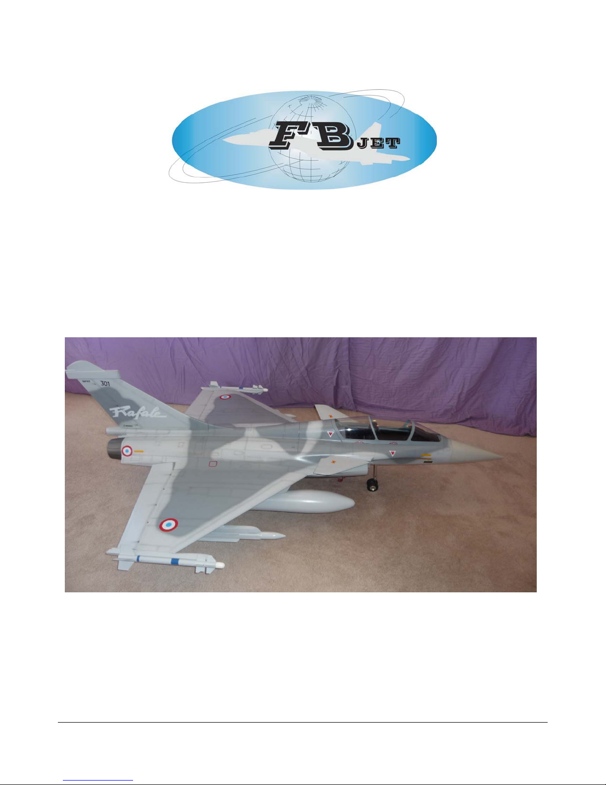
FEI BAO RAFALE
FEI BAO JETS
Rafale Assembly Manual
In collaboration with R/C Jet Models
Written By Rich Miller
1
Page 2

DISCLAIMER:
THIS IS NOT A TOY.
This is a high-performance miniature aircraft, capable of high speeds and damage to life, limb,
and property. The manufacturer and its distributors and author of this manual cannot control
how you assemble this model, what equipment you use to fit it out, or how you fly it, and can
assume no liability whatsoever for any damages that may occur when you fly your aircraft. By
assembling this model, you are agreeing to indemnify and hold blameless the manufacturer
and/or his agents from any and all torts and liability associated with the use of this product.
Please inspect all parts before beginning assembly. If any part appears to be suspect, contact
your dealer or the manufacturer for repair or replacement BEFORE you begin.
Once you have assembled the aircraft, you are the pilot in command and assume any and all
responsibility for the use of the model and any damages that might occur by flying or attempting
to fly this aircraft.
R/C model jets require a high level of skill in both their assembly and their flying. If you do not
feel confident in either your building or flying skills, PLEASE seek assistance from more
experienced modelers. It is a wise idea, no matter what level of skills you possess, to have a
second experienced modeler go over your installation after assembly. A second set of eyes may
spot a problem you have missed. If you have not flown a model like this before, it is HIGHLY
recommended that you get an experienced turbine pilot to do your maiden flight. Very often, the
first few seconds of a maiden flight are critical until the aircraft is trimmed out, and having an
experienced pilot at the controls can make the difference between a wrecked aircraft and once
that enjoys many hundreds of flights. Be sure to select a suitable field for flying...take the time
to find a large paved runway if at all possible, especially for test flights, until you feel comfortable
getting the aircraft in and out of smaller grass fields.
Note: In the USA it is mandatory that you belong to the Academy of Model Aeronautics and hold
a valid Turbine Waiver, please check the local governing rules for operation of R/C model jets of
your location before flying.
Congratulations on your purchase of the Fei Bao Rafale.
Introduction:
You have chosen a model that represents the pinnacle of ARF technology. While there is not a lot of
building to do, there is enough to keep you busy for a few evenings. Even if you have assembled
other ARF jets, we highly recommend following our assembly sequence and procedures.
It was the intent of the author to arrange the construction sequence of this manual in a sequence that
will allow you to move forward. Please remember that just because the model is almost completely
built it does not mean that you can rush through the assembly. It is this authors recommendation that
all factory installed systems i.e. fuel, retracts, and doors be inspected for any possible defects, loose
parts etc. and all fasteners should be secured with Loctite.
Before you begin:
Keep this in mind as you proceed
Look at EVERY assembly step you finish, and ask yourself:
“Is this going to crash my airplane?”
2
Page 3

A chain is only as strong as its weakest link, and this is a high-performance aircraft that will be
very intolerant of sloppy assembly techniques. Even the smallest component is important and
can cause the loss of your airplane, so take the time to do things right, or redo them if they are
wrong. Careful work will result in a long lasting plane that will give you years of pleasure, one
loose component could resulting the complete loss of the aircraft and all of the component
inside of it, additionally someone could even get hurt. So please pause every once in a while
when building and double check your workmanship.
• Clean and inspect all parts. Inventory them against the parts list at the end of the manual
and notify the kit supplier of any missing components as soon as possible.
• If the paint scheme you have selected is glossy, it is recommended that you apply a coat of
wax. This will help resist dirt, stains and fingerprints during construction, and will provide
some limited protection against errant glue.
• Vacuum out the remnants of packing materials that remain in the fuselage.
Adhesives:
The correct adhesive to use for all procedures is Loctite Hysol 9462. This is very strong white epoxy
that is thixotropic. “Thixotropic” means it does not run at all, but stays only where you put it. It is
infinitely superior to regular epoxy, event slow setting epoxy, for our purposes, because of this
characteristic. Regular epoxy will run downhill with gravity as it dries, taking it away from where it is
supposed to be. The downside of Hysol is it takes overnight to dry properly. It is recommended that
you only use a proper Hysol dispensing gun and only the long-type mixing nozzles.
Pneumatic Systems:
Pneumatic retracts typically are the number one maintenance issue with most models however with
proper installation procedures and preventive maintenance this need not be the case. All Fei Bao
jets uses pneumatic gear doors, retracts and brakes. If you follow a few tips you should have a very
reliable leak free operation. Factory installed systems should be inspected for kinked lines, proper
insertion of hoses on fittings and the hose routings should be neat and secure. Take special
precautions to route hoses away from moving gear parts and hot engine areas. It is recommended
that the factory valves, cylinders and brakes be dissembled, cleaned and lubed with a good o-ring
lubricant to ensure reliable operation.
If installing your own pneumatic components it is important to make all cuts in the pneumatic tubing
dead square before installing on the nipples, also make sure that the lines are pushed all of the way
onto the nipples. They should not need to be secured otherwise however you can add fine safety
wire for extra security.
Model Specifications:
Scale: 1/7.5
Length: 80 3/4" (2050 mm)
Wingspan: 56 3/4"(1440 mm)
CG Location 5 1/8” (130 mm) from LE of Wing
Dry Weight: 26-29 lbs (12 Kg to 13 Kg) – Depending if armament is installed
Thrust Class: 22 to 30 lbs (10 to 13.6 Kg)
Servos for Flight Surfaces & Steering (5)
Servos for pneumatic controls (4 or pneumatic valves)
Fuel Capacity Right and Left 33.8 oz ea (1000 ml ea)
Center Tank 24.5 oz (725 ml)
92 oz Total (2725 ml)
Main Tire Diameter 3.34” (85 mm)
Nose Tire Diameter 2.21” (56 mm)
Brakes – Double O-Ring 1.4” dia. (35.5 mm)
3
Page 4

Full Scale Specifications:
Length: 50.20ft (15.30m)
Width: 35.76ft (10.90m)
Height: 17.52ft (5.34m)
Performance:
Max Speed: 1,320mph (2,125kmh; 1,147kts)
Max Range: 1,150miles (1,850km)
Climb Rate: Not Available
Ceiling: 55,118ft (16,800m; 10.4miles)
Hard points: 14 (including two wingtip mounts)
Empty Weight: 19,974lbs (9,060kg)
MTOW: 47,399lbs (21,500kg)
Engine(s): 2 x SNECMA M88-2 augmented turbofan engines with afterburning generating
19,555lbs of thrust.
Parts List:
Major components
Fuselage Nose Section
Fuselage aft section
Canopy
Cockpit Tub
Forward and Aft Equipment tray
Hatch
Bypass
Right and Left Wing panels
Right and Left Elevons
Rudder
Vertical Stabilizer
Right and Left Canard
Two Tail Cones
Right and Left Fuel Tanks
Center Tank
Refueling Probe
Raised Servo Hatch (Wing Servos)
Two Elevon linkage covers
Hinges / Linkages / Hardware kit
Air Kit
Gear Doors and Cylinders factor installed
Factory installed Retracts
Additional Equipment:
While the kit is comprehensive, there are additional parts required as follows:
Recommended Engine Thrust 22 to 30 Lbs
Possibilities include:
• Jet Central Falcon or Super Eagle
• Jet Cat P-80 or P120
• Wren XL
4
Page 5

Recommended Servo List (JR)
• Canard: (1) 8611a
• Elevons: (2)
• Rudder: (1) 3421
• Nose Steering: (1) 2721
• Retracts: (1) 351 or equivalent
• Brakes: (1) 351 or equivalent
Recommended Servo List (Hi-Tec)
• Canard: (1) HS-645MG or HS-5645MG
• Elevons: (2) HS-5955TG (new Number is HS-7955TG)
• Rudder: (1) HS-245MG or HS-5245MG
• Nose Steering: (1) HS-645MG or HS-5645MG
• Retract Valve: (1) HS-225 or equivalent
• Gear Doors (2) HS-225 or equivalent
• Brakes: (1) HS-225 or equivalent
Other Parts
• Bifurcated Pipe
• Pull-Pull Steering Cable
• BVM UAT or equivalent (optional / but highly recommend)
• ½ inch Velcro straps to secure fuel tanks, receiver, air tanks, ECU
• Wire twist tie (optional)
• Blue Loctite
• Glues: Loctite Hysol 9462, Thin CA, 15 minute epoxy
• Electronic gear sequencer(RCBEE from RC Jet Models or equivalent)
• Brake valve or Electronic Actuator
• Batteries, regulator and switch
• Servo extensions (length may vary, depending on receiver placement)
• Ordinance Package
Construction
The order of construction may be changed to suit your personal preference
Note: any fiberglass surface on the inside of the airframe that requires components to be
bonded should be cleaned with solvent to make sure that any mold release agent is removed
and should be scuffed with medium grit sandpaper to promote adhesion prior to gluing.
Step 1: Wings – Hinging of Elevons and Servo Installation
Note: First production kits were supplied with only three hinge points in each Elevon section,
this was found to be insufficient for this large of surface, it is imperative that if you have a
version that is only supplied with three hinges you must add two more hinge points as shown in
Photo 1.
5
Page 6
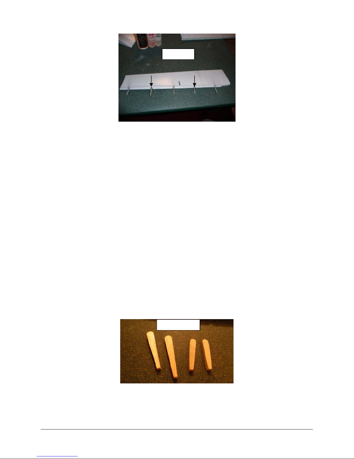
Photo 1
There is no structure for the hinge points to mount to in the Elevon section therefore hardwood
balsa sections must be glued into place and then drilled for the hinge points as show in photos
2 and 3.
Start by making the two extra holes in the leading edge of the surface; the holes are
positioned centered between the existing holes. See Photos 1
Fabricate two filler blocks for each hole, photo 2, the filler blocks are coated with adhesive
and then inserted into the hole that was created in the surface, photo 3, use an x-acto knife
to maneuver the parts around once inserted into the hole. The two blocks should be
positioned so that the joint that forms between then is centered in the cutout hole in the
leading edge.
After the adhesive is fully cured, drill the hole required for the hinge point photo 4, I used
Robart large hinge points for the extra hinges required.
Now all hinge points can be glued into the surface, it is recommended to used some oil on
the hinge pin to make sure that adhesive does not work its way in and cause a bind, see
photo 5. Make absolutely sure that oil does not get on the part of the hinge that will be
glued; any stray oil can be removed with solvent.
After all hinge point are inserted, go back and check the depth of insertion and alignment of
the hinges before the adhesive cures. Make sure adhesive did nit get into the hinge pin
locations. Any extra adhesive should be removed; a toothpick works well for getting into
tight spots.
Note: Nail polish remover works well as a solvent to remove pre-cured adhesive and it did not
attack the paint on this particular model, see photo 6; however, before any solvent is used it
should be tested on an inconspicuous area of the paint.
Photo 2
6
Page 7
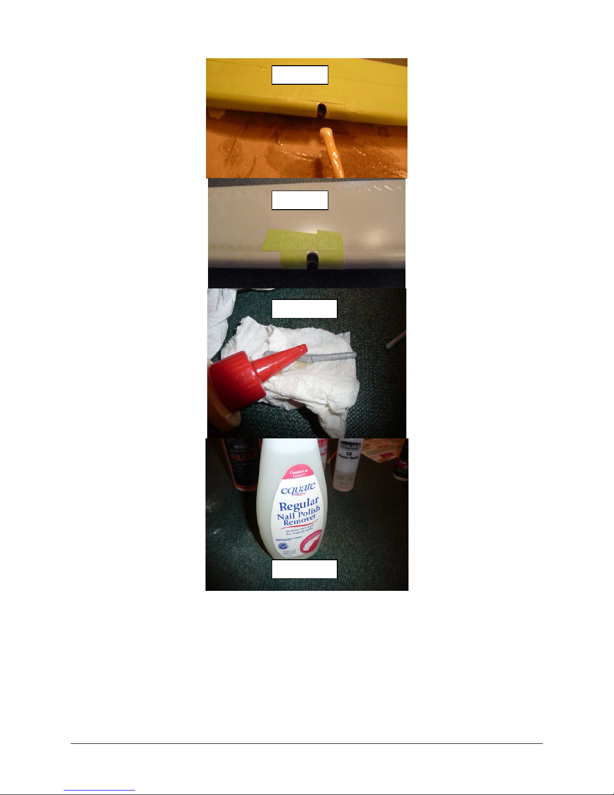
Photo 3
Photo 4
Photo 5
Photo 6
Next the position of the new hinges needs to be transferred to the trailing edge of the wing.
Drill the two additional holes for the new hinge locations. As in the case of the surfaces
there is no structure in the TE of the wing at the new hinge point locations. A hard piece of
balsa to act as a doubler can be inserted through the servo bay cut out for the one hinge
point location. The additional hinge location will require the TE of the wing to be drilled to fit
a dowel rod that will hold the hinge. The rod should be a bit longer that the hinge point
section to be glued.
Glue in the dowel rod and let the adhesive fully cure before drilling the hinge point hole.
Next the control horns need to be positioned and the slot cut out for its mounting. Start by
inserting the surface into the wing. I used masking tape on the area of the surface that will
require the slot to be cut. See Photo 7
7
Page 8

Position your servo in the wing pocket and then take a straight edge and create the line from
the servo arm to the horn location on the surface. Mark the horn position on the tape that is
on the surface, this will now serve as the slot guide.
When cutting the slot into the surface great care should be taken as not to cut into the LE
structure of the surface, cutting the LE material could cause a failure of the surface in flight.
After creating the slot the horn can be glued in, before doing so make sure to take some
sand paper and rough up the area on the horn where the adhesive will make contact.
A uniform adhesive fillet should be created around the control horn and the control surface,
any extra adhesive should be removed; a toothpick works well for getting into tight spots.
Photo 7
Trial fit the Elevon into the wing panel, see photo 8, the surface should be inserted so free
movement is achieved in both direction and no binding exists between the fiberglass TE
extensions and the surface. If travel is limited by the TE of the wing then using a long
sanding bar sand the TE fiberglass until free movement is achieve to the recommend limits
of movement, i.e. elevator should have 25 to 30 mm (1” to 1 3/16”) of up movement in both
directions.
The completed Elevon can be glued into the wing panel using the same precautions as
mentioned above for keeping the adhesive out of the hinge points.
Before adhesive cures make sure to double check the alignment and movement of the
Elevon and adjust as necessary.
Photo 8
8
Page 9
Wing Servo Mounting:
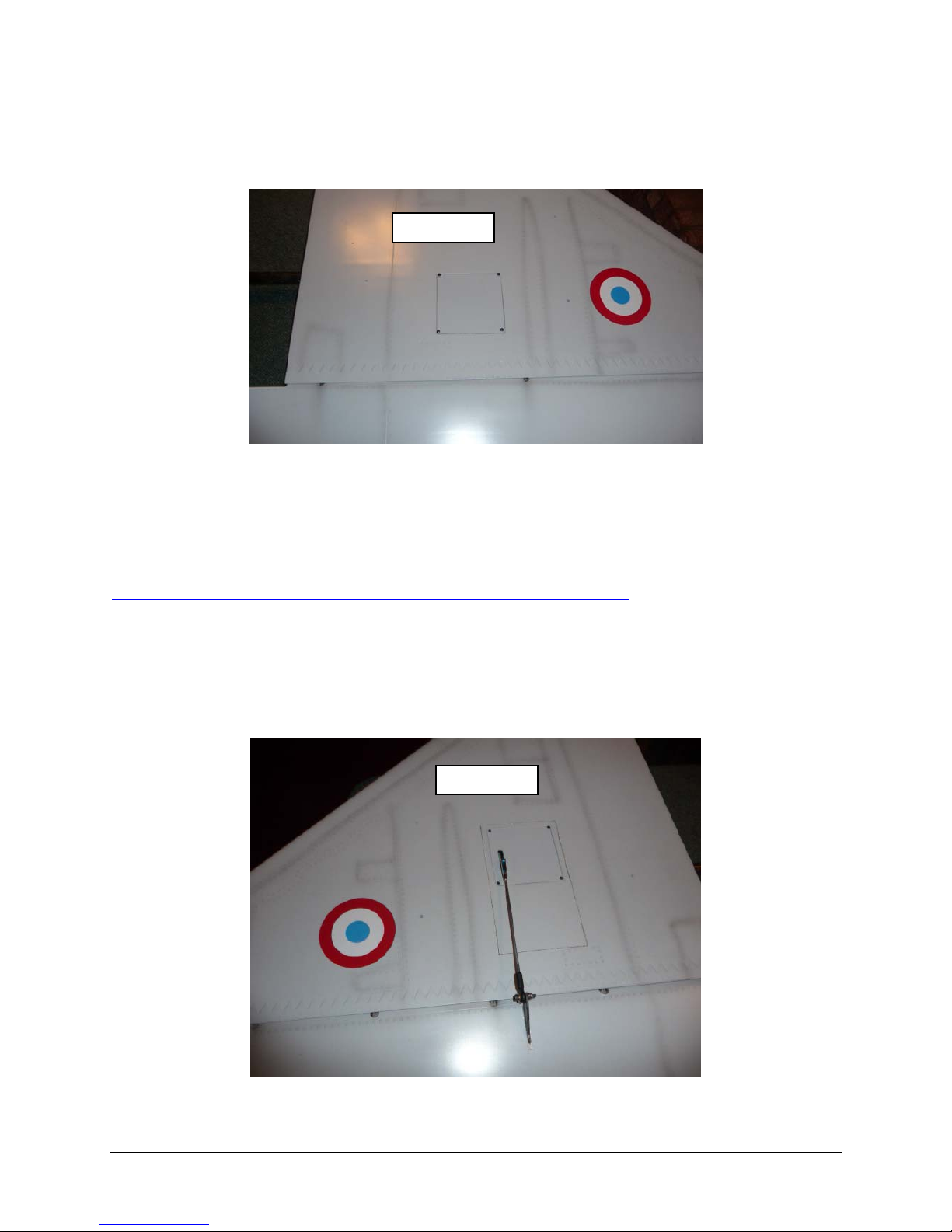
The production kit that was used for this manual had the servo bay cut outs position far back
towards the TE of the wing; this creates a height issue when using standard sized servos and
the stock flat hatches; see Photo 9.
Photo 9
The kit was also supplied with extra raised hatches to help solve this issue. I will cover the
servo installation with the raised hatches in this manual; however, for the model that I built I
devised a method to utilize the flat hatches. This required structural modifications not covered in
this manual (see Photo 10 for preview) and is covered in detail on the build thread that I started
on RC Universe, see the following thread for the details:
http://www.rcuniverse.com/forum/m_8458710/mpage_1/key_/tm.htm
A brief synopsis of the modifications:
Cut out section of wing skin
Remove factory servo mounting structure
Cut out new servo mounting structure from drawing and glue into place
Rotate section of wing skin 180 degrees and re-glue into place
Factory Supplied Servo Bay:
Photo 10
9
Page 10
Note: If you kit is supplied with the factory positioned servo bays located back towards the TE
of the wing (see Photo 11) then the plywood mounts may require some modifications in order to
mount the servo of your choice. Due to the large surface of the Elevon it is recommended to
use a standard size digital servo with metal gears which will supply plenty of reserve torque.
Photo 11
Remove the factory supplied flat servo cover and put aside, locate raised covers and trial fit
into openings, if required trim to fit.
Attach the L brackets to the servos. The servos will face in opposite directions when
installed with the spline end towards the TE of the wing.
Note: It is the authors practice not to use the rubber grommets supplied with the servo for
mounting of servos in jet airframes as vibrations are not an issue.
Using your receiver or servo driver, find servo neutral and attach the heavy-duty servo arm, I
use the aluminum arms supplied with the Hi-Tec HS 5955TG servos that were used.
Pull the servos through the wing to the roots, the stock leads should be of sufficient length;
label the servo wires for Elevons.
Position the servos onto the mounting tabs. You may also need to trim the lip of the servo
well slightly to provide clearance for the aileron servo arm.
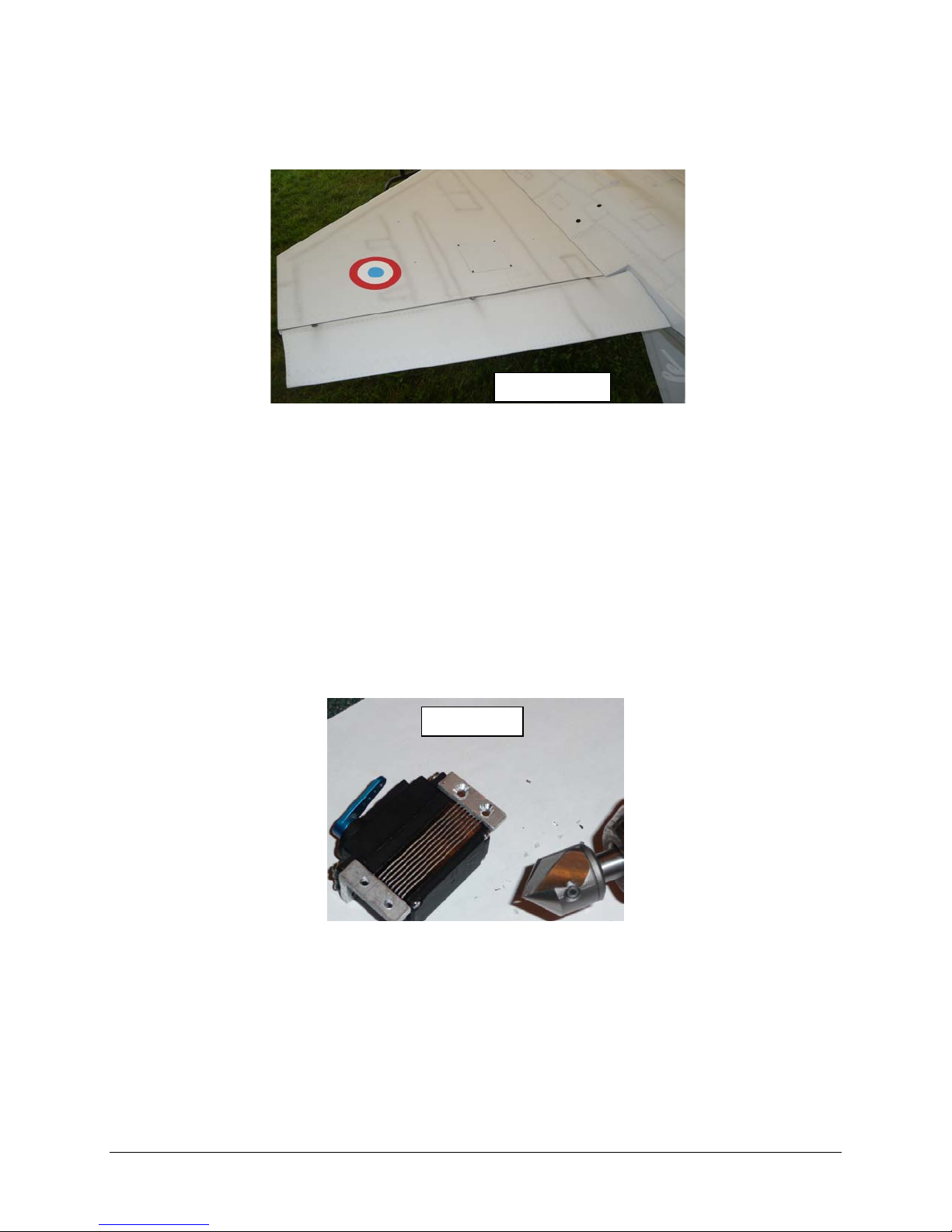
Using a countersinking tool create a countersink area large enough to fit the flat head screw
in the L brackets, see Photo 12
Photo 12
Using great care not to pierce through the top surface of the wing, drill and screw the servos
in place using appropriate flat head type wood screws.
Locate/mark & cut slot position in hatch for the servo arms and then install hatch, see photo
13.
Assemble the Elevon linkage; you may need to enlarge the hole in the control horn with a
7/64 inch drill for the connecting bolt. Do not over tighten this bolt as the rod will bind as the
Elevon is actuated.
10
Page 11
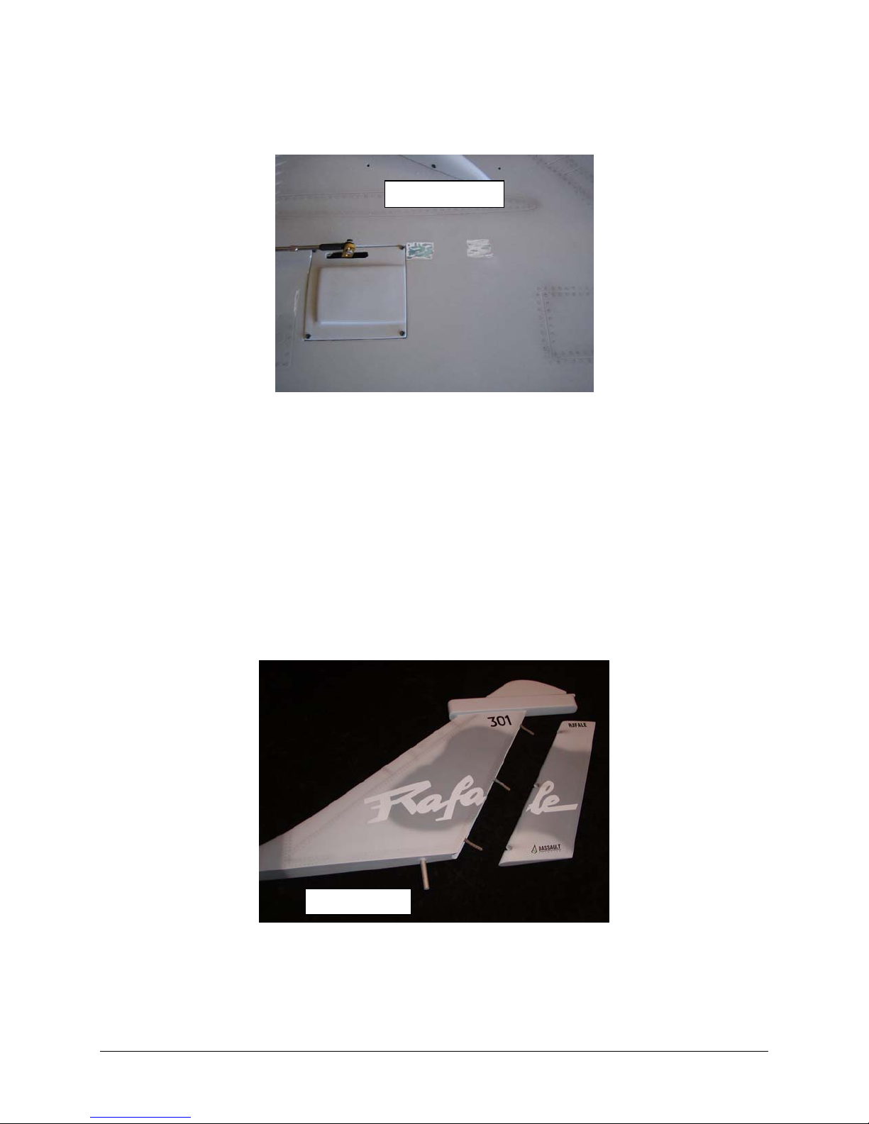
Locate and prepare the area on the wing for the mounting blocks for the linkage covers, see
photo 13, glue blocks in place; after the adhesive cures mount linkage covers with small
wood screws.
Photo 13
Repeat procedure for the other wing. Be sure to keep the linkage lengths equal.
Step 2A: Vertical Fin and Rudder
This manual will provide two options for mounting the rudder servo, the first one will be the
factory intended method (concealed), and the second will be the author’s alternative method.
The factory intended method for installing the rudder servo features a hidden linkage design; the
servo will be installed in aft section of the fuselage to give the Rafale a scale look. This method
requires the use of a pin and socket arrangement to transfer the motion from the servo arm to
the rudder. The hardware kit supplied has the components needed for this installation if the
builder chooses. The following factory photos detail the placement of the required holes and
components.
Photo 14
11
Page 12
)
1.18” (30 mm
Pin that will be glued
into the above hole, the
small end faces down,
insert pin up to the
Photo 15
shoulder.
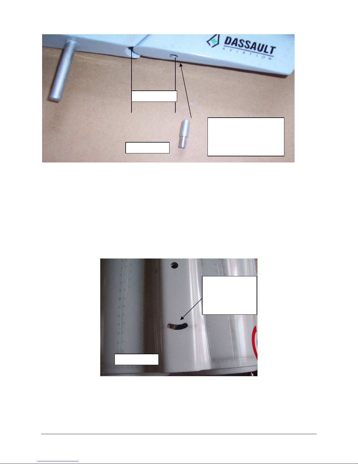
Start by gluing the three hinge points to the fin, after they have cured then glue the hinge
points to the rudder, see photo 14. Follow the same steps as in the Elevon hinging
procedure.
Locate the drive pin position in the rudder assembly, drill the hole in the location shown in
photo 15, and then use adhesive to secure the pin and let the adhesive fully cure.
To find the correct placement of the slot temporally position the rudder and fin assembly
onto the fuselage and trace the arc of the rudder mounted pin onto the top of the fuselage,
masking tape applied to the fuselage in the area that the marking is needed works well.
Cut the slot in the fuselage as shown in photo 16.
Trace Slot
position using
rudder and the
pin as a guide,
then cut slot
Photo 16
Note: It is recommended that a standard sized servo be use for this method.
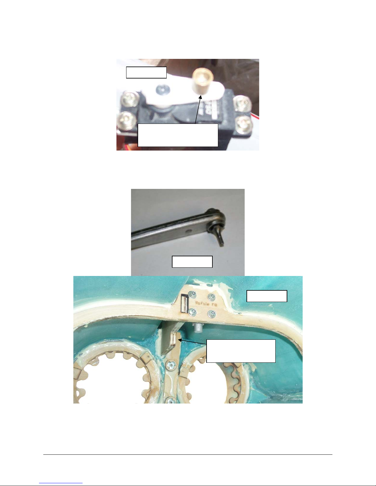
Prepare the heavy duty servo arm by mounting the cup assembly as shown in photo 17.
Mount The L brackets to the servo; the L brackets should be on the right side of the servo
with the spline end of the servo towards the front of the airframe as shown in photo 20.
12
Page 13
Note: It is the authors practice not to use the rubber grommets as supplied with the servo for
mounting servos in jet airframes as vibrations are not an issue.
Align the servo shaft by using your receiver or servo driver to find the servos neutral point
and then attach the heavy-duty servo arm with the arm placed as shown in Photo 17.
Photo 17
Cup assembly mounted
to heavy duty servo
Mount the rudder servo to the bulkhead position as shown in photo 19 & 20 using socket
headed wood screws; the arm will be facing towards the rear of the fin. Verify that the cup
receptacle follows the arched cutout in the fuselage.
Hint: a ratchet type angled Allen driver works well in confined spaces, see photo 18.
Photo 18
Photo 19
Mount servo on this
side of former
13
Page 14
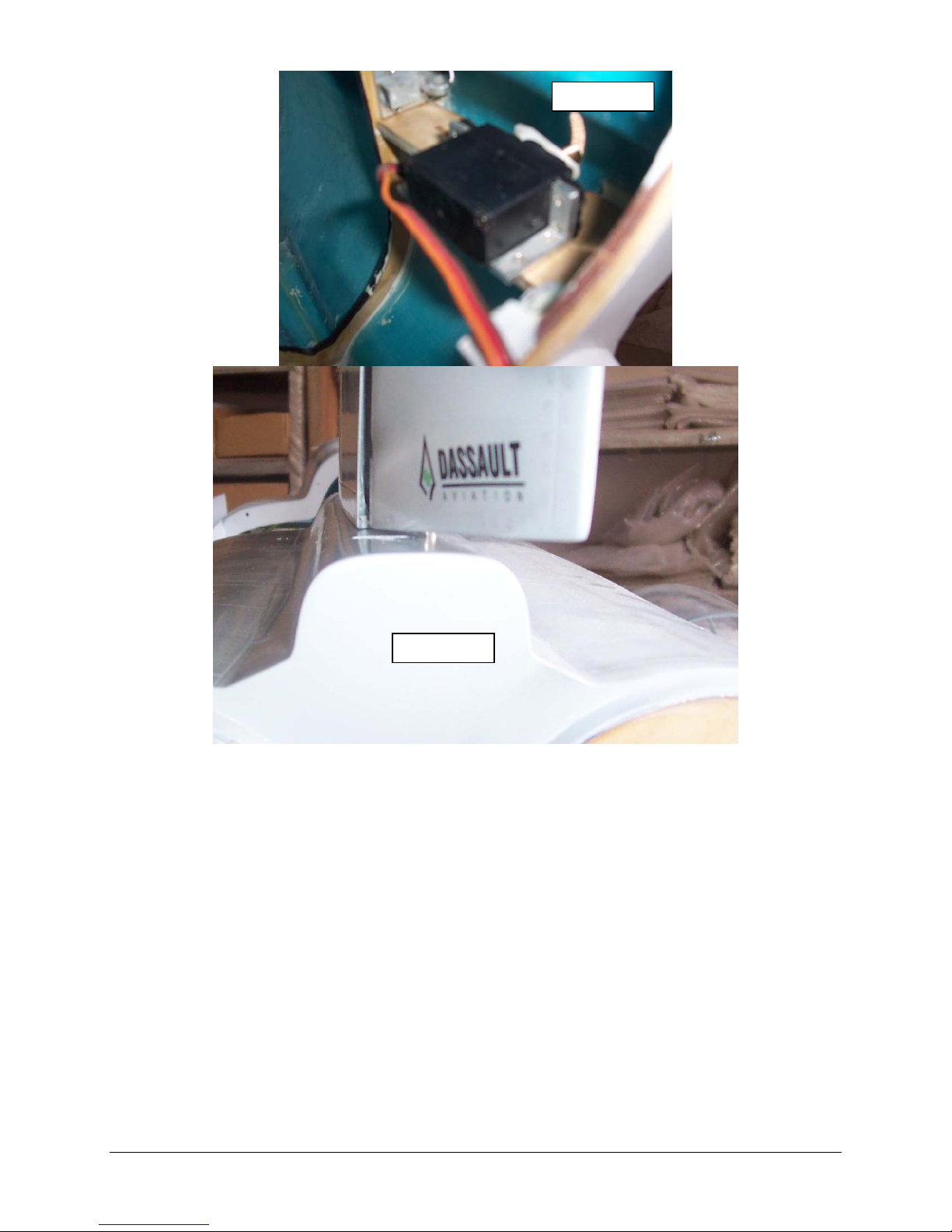
Photo 20
Photo 21
Check for free movement of the rudder, insert the vertical fin into fuselage and verify
operation using your receiver or a servo driver, see photo 21.
If the rudder movement is satisfactory then permanently mount fin to fuselage by tightening
the rear clamping bolt and inserting the front pin bolt and washer, see photos 22 & 23.
14
Page 15
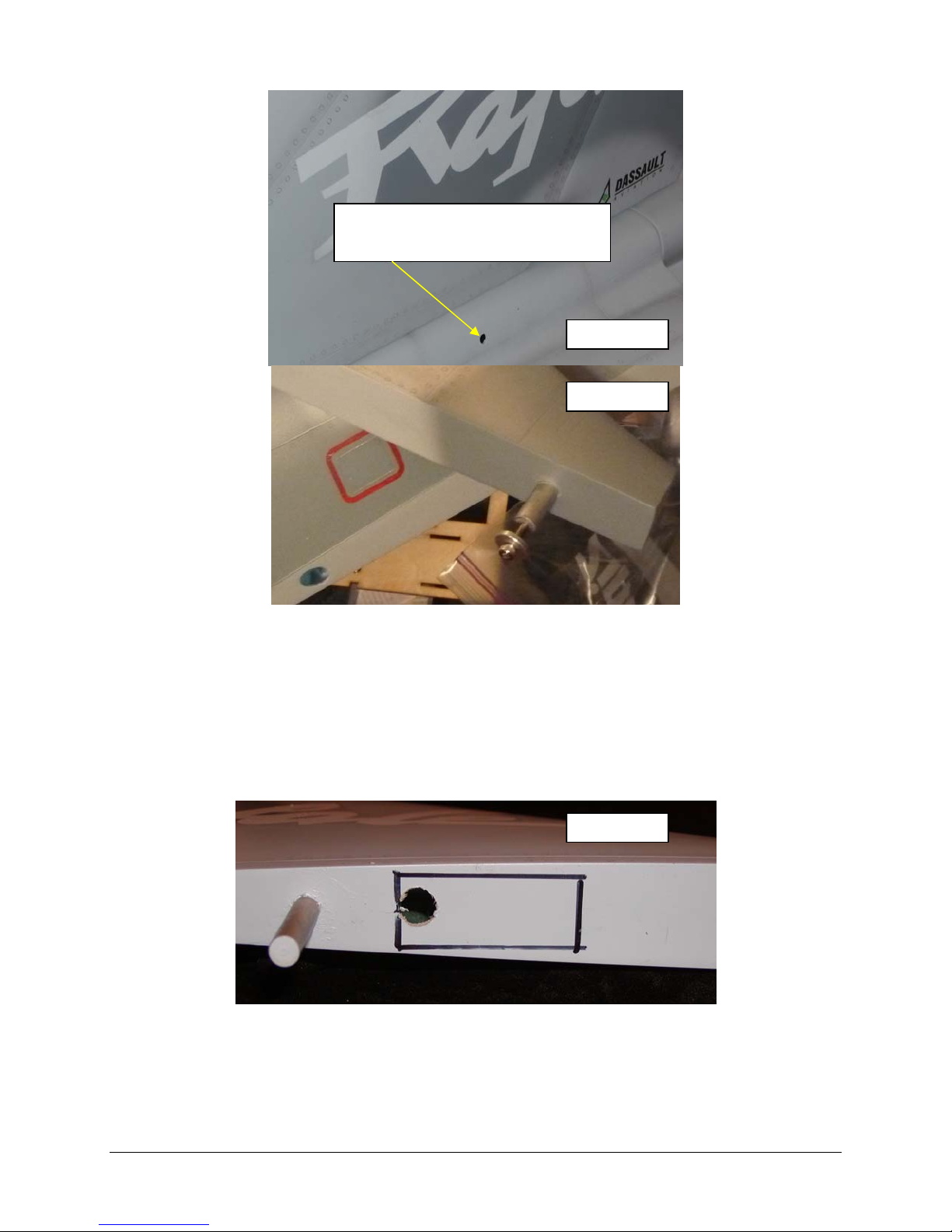
Fin Clamp Bolt Hole
Photo 22
Photo 23
STEP 2B: Alternate Vertical Fin Servo Mounting Method
The alternate method for installing the rudder servo is directly in the vertical fin, this method
provides for the use of a traditional linkage arrangement. The advantage of this system is
increase rudder deflection and less chance of surface flutter.
The cut out in bottom of fin measures ¾” x 1 7/8”, cut slot as shown, see photo 24.
Photo 24
From scrap wood fabricate a mock-up of the servo top case; this will serve as a fixture for
locating the servo mounting blocks. See photo 25 & 26 – the servo used for the subject of
this manual was a HiTec HS-245.
Material Servo Blocks:
Front 3/8” sq x 1”
Rear 3/8” x 1/4” x 1”
15
Page 16
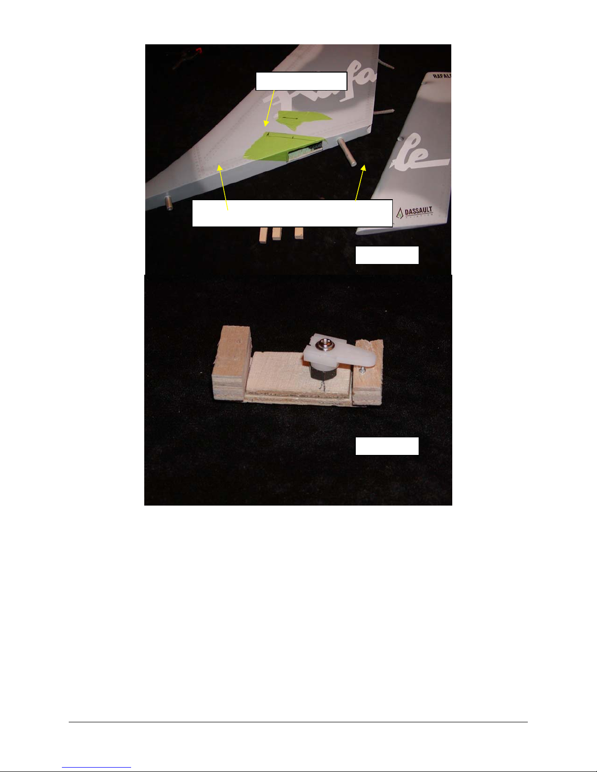
Blocks that will be glued into place
Photo 25
Photo 26
After prepping the fin, make sure to scuff the inner surface with medium grit sand paper,
glue in the mock up servo fixture with the mounting blocks as shown in photo 27. Make sure
not to get glue on the mock up servo fixture or it will be difficult to remove later.
After the adhesive has cured on the mounting blocks remove the mock up servo fixture.
16
Page 17
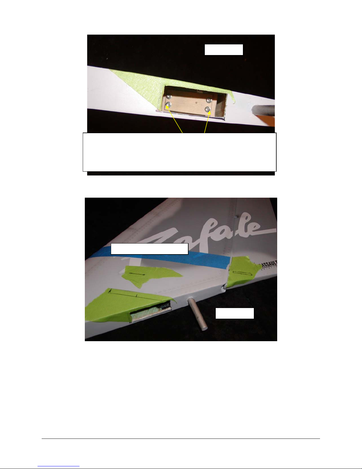
Photo 27
After adhesive is dry remove fixture. The servo installs with the
top of the servo mounting tabs making contact with the servo
rails, if the servo has reinforcement on the top tab it may need to
be removed so the servo will sit flush on the mounts. The servo
spline faces the front of fin.
Layout the locations for the servo arm cut out and control horn as shown in photo 28
Layout hole positions
Photo 28
Using your receiver or servo cycler power up the servo and set it at neutral. Attach the
control arm at a vertical position. Mount servo in fin as shown in photo 27. The slot may
need to be enlarged in size slightly with a small file if the servo arm binds.
Secure control horn with adhesive and let cure.
Construct linkage as shown in photo 29 &30.
17
Page 18
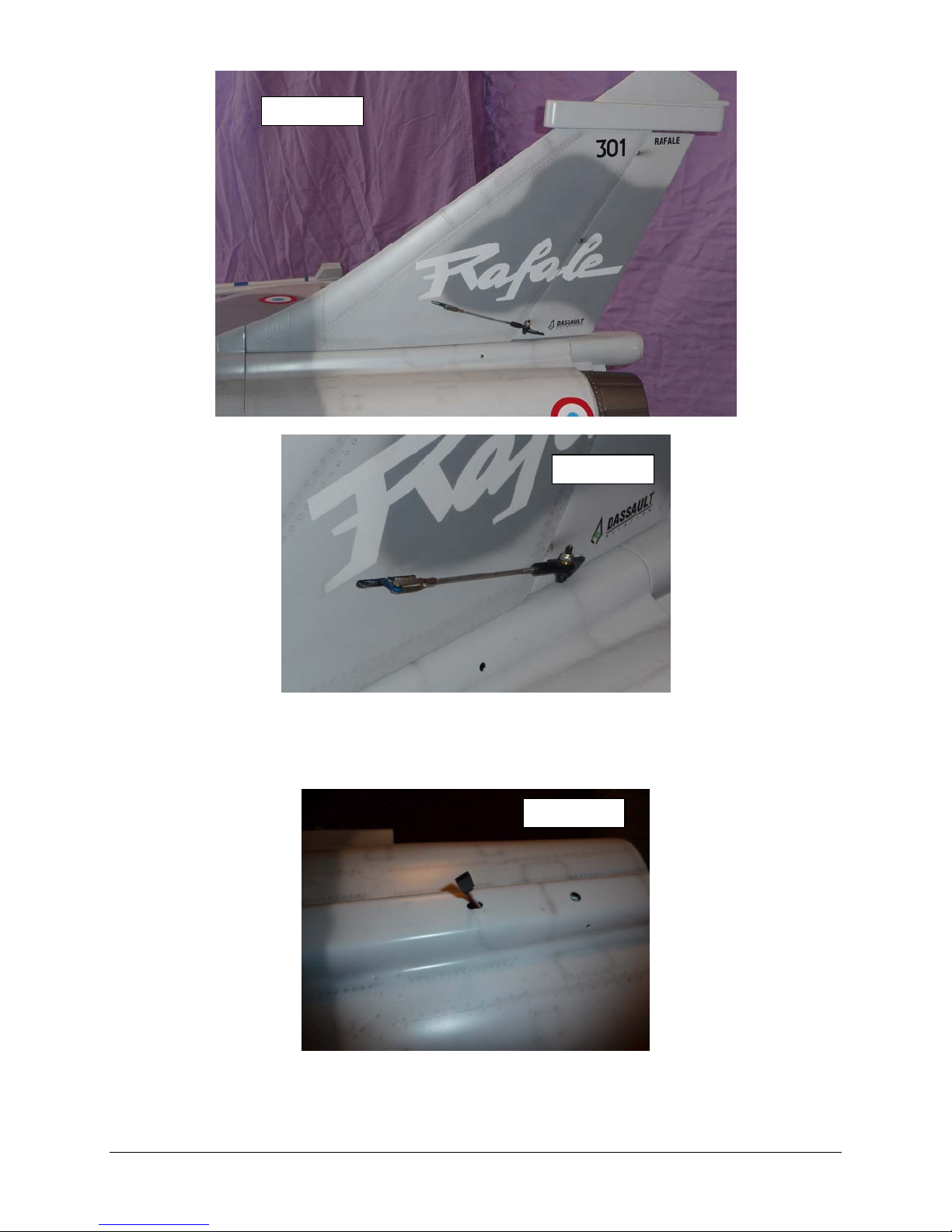
Photo 29
Photo 30
Assemble the rudder linkage; you may need to enlarge the hole in the control horn with a
7/64 inch drill for the connecting bolt bolt. Do not over tighten this bolt as the rod will bind as
the rudder is actuated.
Cut a servo lead access hole in the fuselage as shown in photo 31.
Photo 31
Connect your servo extension and secure with tape or heat shrink tubing.
Secure the front of the fin to aft fuselage with the supplied bold and large washers, see
photo 23, and use Loctite on the threads. Secure the clamp bolt on the fin see photo 22.
18
Page 19
Step 3: Air Tank Installation
The air tanks can be installed in various locations in the airframe, the location I choose was in
the area between the canopy and the rear hatch, see photo 35. There are many methods
available to secure the air tanks, a few include mounting with adhesive backed Velcro™,
permanently glued in with Goop™, or mounted to a tray with Velcro™ straps or Ty-Raps.
The method use here will be to make a mounting tray and utilize Velcro straps.
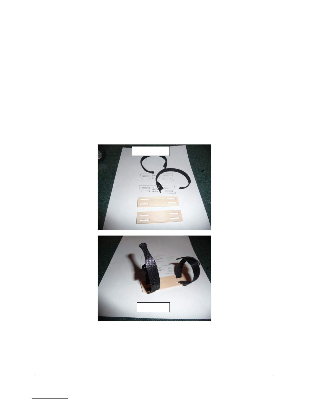
If a removable air tank installation is desired fabricate the air tank hold down brackets from
the attached templates, see photo 32.
Feed the Velcro straps through the slots and around the tank to secure, see photo 33 & 34.
Make sure to prep the area in the fuselage by sanding and cleaning where the plywood hold
down plate will be attached.
Glue in the plywood hold down plate with the tanks attached; temporally hold in place by
stuffing some foam rubber in between the air tanks and the inlet housing, see photos35 &
36.
When the adhesive is cured remove the temporary foam, you tank installation is complete.
Photo 32
Photo 33
19
Page 20
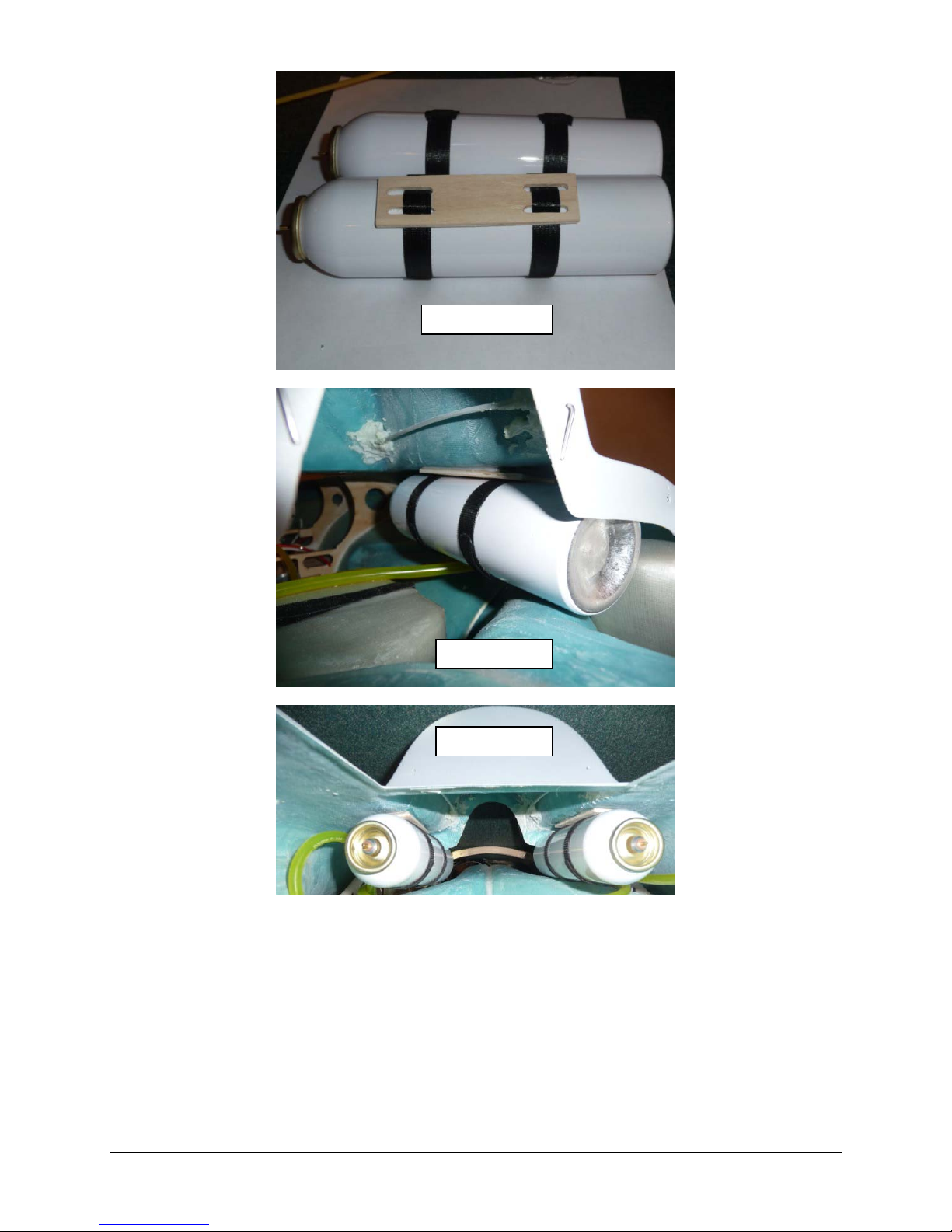
Photo 34
Photo 35
Photo 36
20
Page 21
Step 4: Fuel System
If your model is provided with a factory plumbed fuel system it is recommended that you
disassemble and inspect the tank hardware. The process used to cut the tubes at the factory
may leave behind a ridge that constricts fuel flow and could result in excess tank pressure /
restriction and leakage. If the tubing is not constricted, skip forward to the leak check. The
author recommends that the factory supplied tubing be replaced with large Diameter Tygon™
Tubing; and 3/16” Brass tubing. Larger tubing should be used for the interconnections of the
tanks and the vent lines. The author’s model was built connecting the three tanks in series, in
this configuration it is imperative that the larger diameter tubing be used to reduce the restriction
developed in the fuel system. The two saddle tanks may also be connected using tee fittings
feeding the main tank, this is up to the builder preference as tee fitting are provided with the
hardware package. All fuel system lines should be properly inserted onto the tubing and safety
wired to prevent unwanted and potentially harmful leaks.
Note: Restriction in the fuel system may cause performance issue with your turbine such as not
allowing proper full speed RPM, abnormally high pump pulse width numbers and or excessive
stress placed on the tanks while fueling your model due to expansion cause by air not venting
out of the tanks fast enough.
Note: Total Fuel System Volume of the Rafale supplied tanks is 92 oz (2725 ml)
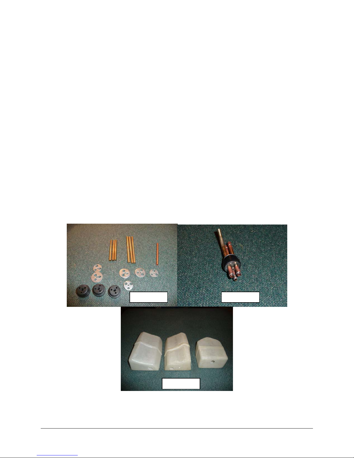
Photo 37 shows larger diameter tubing and the tank hardware that has been drilled out.
Photo 38 shows keepers soldered onto the tubes.
Photo 39 shows the factory supplied saddle and main tanks.
Photo 40 shows optional aluminum fuel tank fitting glued into the tank openings.
Photo 37 Photo 38
Photo 39
21
Page 22
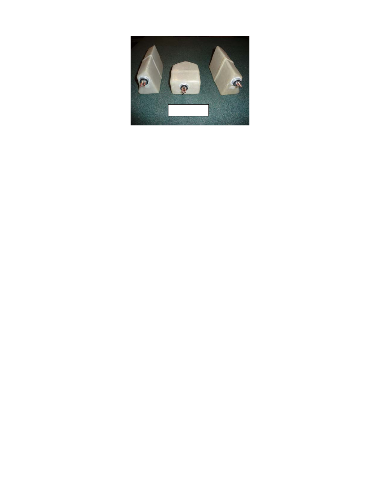
Photo 40
If you are using the factory installed fuel tank components please follow the step outlined below:
Loosen the Philips head screw and remove the stopper assembly from the tank.
Use a small, round Perma-Grit rat tail file or an X-acto knife to remove the excess metal
inside of the cut ends of the tubes. You will need to inspect the ends of all tubes. Another
good method is to use a countersink tool to de-burr the tubing, as you want to create an
internal chamfer.
When finished, make sure to blow out the metal fragments and clean up any sharp edges.
While the components are apart, check the Tygon pickup line for equal lengths in both
saddle tanks. They should be long enough to reach the back of the tanks without being so
long as to restrict their ability to move to the top of the tank when the aircraft is inverted.
You should also notch the vent tube with a small file to provide for continued air flow should
the tube come into contact with the top of the tank.
Make sure the bends to the vent tubes applied at the factory have not restricted airflow to
any significant extent. Also, check the Tygon for any nicks or cuts and secure to the tubing
with wire ties before re-assembly.
Once the tanks are back together, they should be leak checked before installation in the
aircraft. Connect extra lengths of fuel tubing to the fuel and vent lines and submerge the
tank in water. Pinch off one line and gently pressurize the tank by blowing into the other,
looking for signs of air bubbles. If the tank shows evidence of air leakage around the vent
cap, tighten the Philips head screw and check again. If you have a stubborn leak, you can
re-tap the inner plate for a slight larger 6/32 cap head bolt.
It is recommended that you mount the main fuel tank so as to be able to remove it for
maintenance in the future. There are many methods available to secure the main tank, a few
include mounting with adhesive backed Velcro™or mounted to a tray with Velcro™ straps or TyRaps. The method use here will be to make a mounting tray and utilize Velcro straps.
The plate shown in photo 40 can be fabricated from the supplied template and plywood, the
Velcro strap in inserted into the hold down plate before it is glued into the fuselage.
Gluing the spacer block to the bottom of the tray, when cured proceed to next step, see
photo 41.
Glue the tank mount plate to the fuselage floor; make sure to prep the area by sanding the
fiberglass with medium grit sand paper, see photo 42 for placement location.
22
Page 23

Photo 41
Spacer Block
mounts
underside in this
area
Velcro
Strap
Photo 42
Spacer block glued under center of
tank mounting plate prior to gluing
plate to fuselage
Position the main tank and apply a Velcro hold down strap, see photo 43.
Photo 43
Use Velcro Strap
around main tank
Remove the engine mounting rails and slide the saddle tanks in position, see photos 44 &
45.
23
Page 24
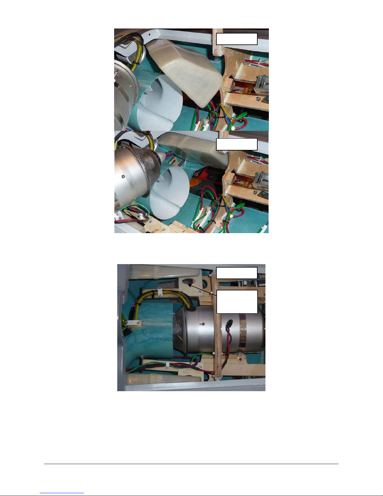
Photo 44
Photo 45
The plywood tank holders shown in photo 46 can be fabricated from the supplied template
and plywood to hold the saddle tanks in position after the engine rails are repositioned.
Photo 46
Saddle Tank
positioning
plates
For a parallel saddle tank system connect two pieces of fuel tubing approximately 6”
(150 mm) long to the fuel pickup tubes in each saddle tank and bring them together with a
“Y” fitting just above the intakes.
Repeat this process for the vent tubes in the saddle tanks.
Run a length of fuel tubing from the “Y” fitting connected to the fuel pickup tubes of the
saddle tanks to the vent tube of the main center tank.
Attach a length of tubing to the “Y” fitting connected to the vent tubes on the saddle tanks.
The vent fitting will be positioned in the forward fuselage … a pigtail of approximately 8”
24
Page 25
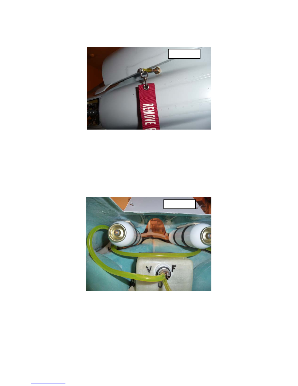
(200 mm) should be sufficient. Connect the vent from the saddle tanks to a bulkhead vent
fitting located on the bottom of the fuselage, the fitting should be located between on of the
intake ports to provide protection in case of a gear up landing, see photo 47.
Photo 47
Connect a length of tubing that will run to UAT to the fuel pickup tube on the main center
tank.
Safety wire all connections at this time.
If you use plastic wire ties (Tyraps) to bind the fuel tubes together for a neater installation,
make sure not to over-tighten and pinch down on the flexible fuel tubing.
For a series connected saddle tank system run a length of tubing from pick-up line of one
saddle tank to the vent line of the other. Then run a length of tubing from the pick-up of the
second tank to the vent of the main tank, see photo 48. The main vent from the first tank in
the series line should be run to the fitting exiting the airframe on the bottom. See Photo 47
Photo 48
25
Page 26

Step 5: Nose Gear Door and Cylinder Installation
Note: If your model came with factory installed gear doors skip this step.
The order in which the doors are installed is up to the builder; this manual will start with the front
single door, and then proceed to the two double doors.
If required cut out nose gear opening with a Dremel cutoff wheel or other appropriate means
to allow for gear door installation. Make sure that a lip is remaining after the final sanding to
size is completed, see photos 49.
The doors may require some minor trimming to fit the fuselage opening, also a bevel may
need to be sanded on the hinge side of the doors to clear the lip in the fuselage, make any
adjustments that are required during the fit up of the doors.
The hinges are installed on the right side of the front single door, see photo 50. The right
side is assumed to be viewing the fuselage from the rear and it is sitting on the gear. Due to
the geometry of the hinge locations the front doors may require a small wedge (see photo
52) to be placed between the door and the hinge in order to gain the required clearance to
open.
After locating the hinge positions mark and drill the holes in the door and the fuselage.
The front most hinge on the on the single large nose wheel door will need the extended tab
removed from the hinge to allow clearance for the tires when the gear is retracted. This can
easily achieved with a Dremel cut off tool.
Install the two back nose doors using the same type of procedures as described for the
single door, except the back two doors should not require the wedge between the doors and
hinge. See photo 51.
Door cylinder installation, the front door cylinder is installed on the right side of the fuselage
and is mounted to the rear hinge.
To get the proper location of the wooden mounting block connect the cylinder rod to the
door hinge; temporarily connect the other end of the cylinder to the wood mounting block.
Blocks shown in photo 53.
Extend the rod completely and hold the front door to its maximum open position, mark the
location of the wood block on the inside of the fuselage, position is shown in photo 54
Prep the area where the wood block will be bonded to the fuselage by lightly sanding,
disconnect the cylinder and glue the block to the fuselage with adhesive. The block should
be held in position with masking tape or other appropriate means until completely cured.
When the mounting block is cured make the final attachment with the supplied hardware,
Loctite® should be used to prevent the screws from coming loose, be careful to keep the
Loctite® from contacting plastic parts as it may cause them to become brittle.
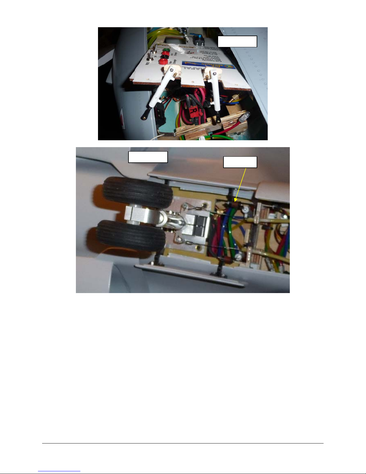
The door cylinders for the two rear nose wheel doors are connected to the front hinges and
may require a spacer between the hinge and cylinder attachment point. The spacer may be
required in order to keep the cylinders in a perpendicular position to the bulkhead, see photo
56.
The other end of the cylinders for the two front doors are attached to the wooden mounting
blocks that are bonded to the top side leading edge of the rear equipment tray, see photos
54 & 55.
To set the mounting block position, temporarily attach the cylinders to the front hinges, and
then extract the cylinder rods fully. The front mounting tray will need to be fastened in
position.
Open the two doors and hold in their full open position while positioning the mounting blocks
in their appropriate position. Mark the mounting position on the tray and also mark where
the cylinder mounting screws will be drilled into the blocks.
26
Page 27
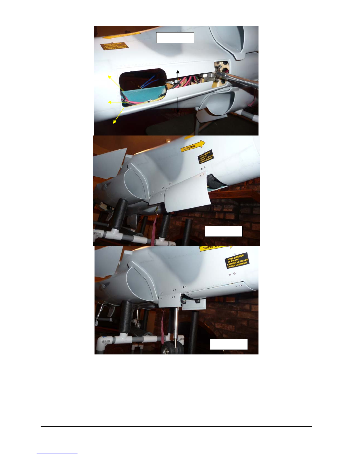
Photo 49
Photo 50
Photo 51
27
Page 28
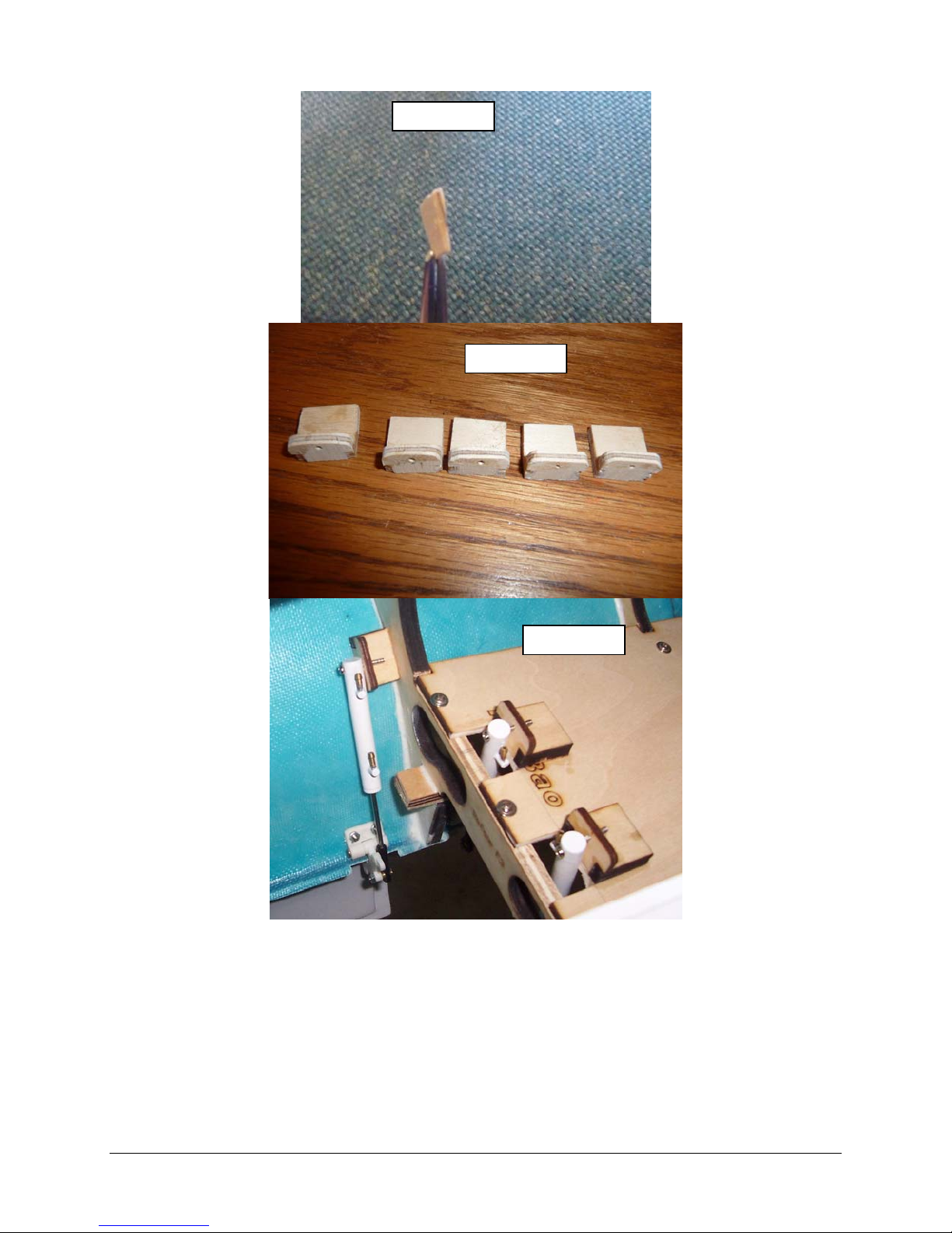
Photo 52
Photo 53
Photo 54
28
Page 29
r
Photo 55
Photo 56
Space
29
Page 30
Step 6: Main doors
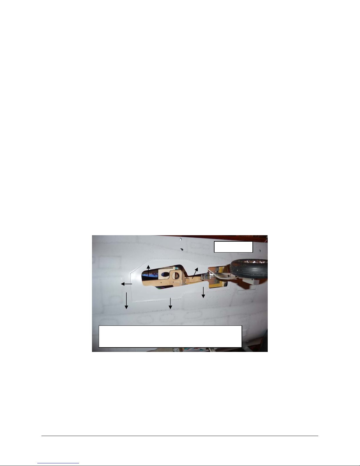
If required cut out main gear openings with a Dremel cutoff wheel or other appropriate
means to allow for gear door installation. Make sure that a lip is remaining after the final
sanding to size is completed, see photos 57.
The doors may require some minor trimming to fit the fuselage opening, make any
adjustments that are required during the fit up of the doors.
The hinges are installed on the inboard side of the main doors, see photo 58, 59, 60 & 61.
After locating the hinge positions mark and drill the holes in the doors and the fuselage.
The front most hinge on the on the front main doors will need the extended tab removed
from the hinge to allow clearance for the tires when the gear is retracted. This can easily
achieved with a Dremel cut off tool.
After the main doors are hinged and fitted the Door cylinder installation may proceed, the
door cylinders (photo 62) are installed as shown in photos
To get the proper location of the wooden mounting block connect the cylinder rod to the
door hinge; temporarily connect the other end of the cylinder to the wood mounting block.
Blocks shown in photo 63.
Extend the rod completely and hold the main doors to in their maximum open position, mark
the location of the wood blocks on the inside of the fuselage, block positions is shown in
photos 64 & 65
Prep the area where the wood blocks will be bonded to the fuselage by lightly sanding,
disconnect the cylinder and glue the blocks to the fuselage with adhesive. The blocks should
be held in position with masking tape or other appropriate means until completely cured.
When the mounting blocks are cured make the final attachment with the supplied hardware,
Loctite® should be used to prevent the screws from coming loose, be careful to keep the
Loctite® from contacting plastic parts as it may cause them to become brittle.
Photo 57
Cut out wheel opening just inside of the molded
lines on both main door openings
30
Page 31
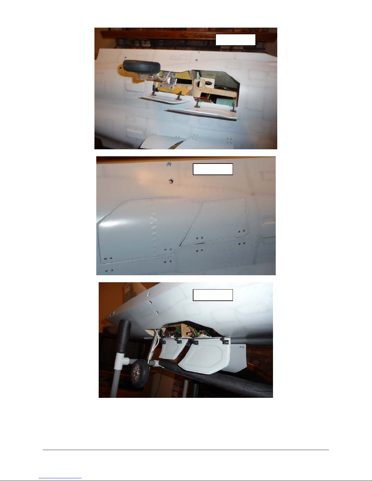
Photo 58
Photo 59
Photo 60
31
Page 32
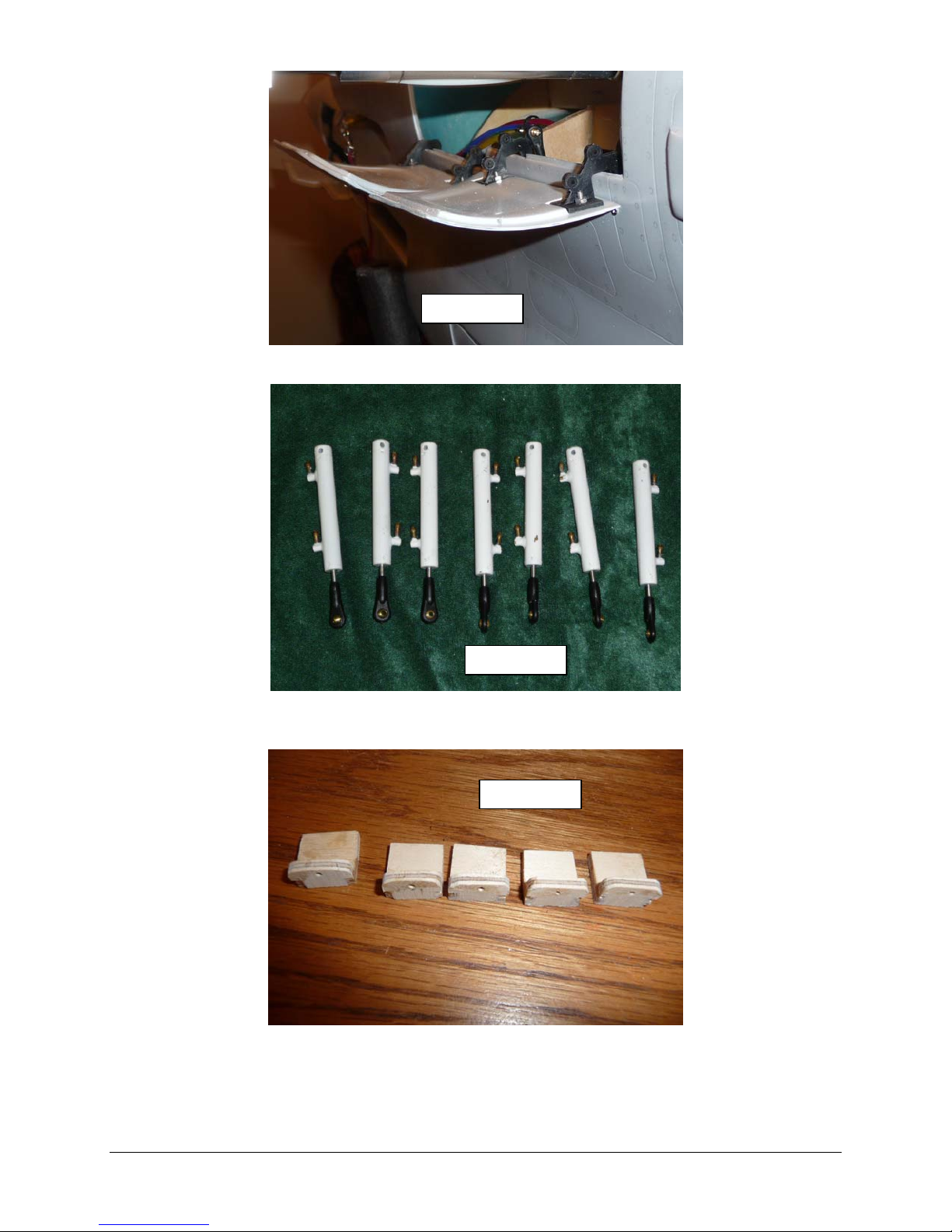
Photo 61
Photo 62
Photo 63
32
Page 33
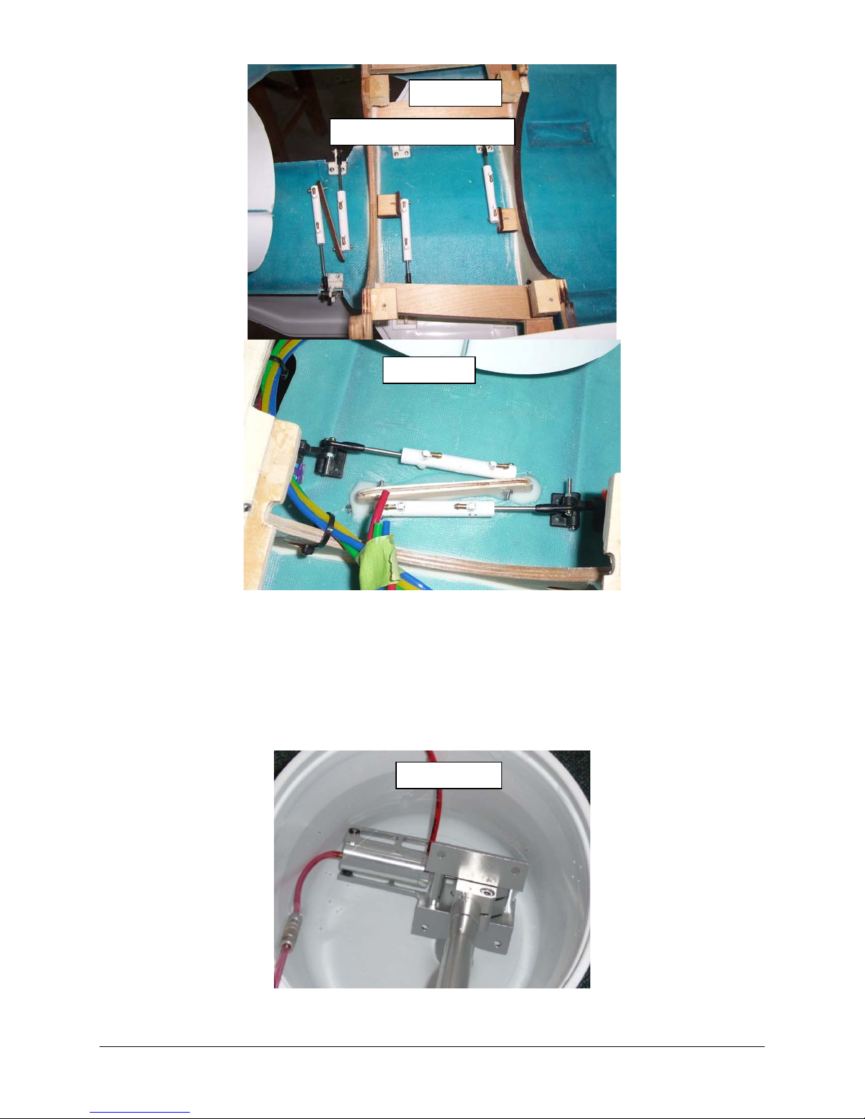
Photo 64
Locating Cylinder
Photo 65
Step 7: Nose Retract Unit Installation
Before installing the nose retract assembly, remove the strut set screws one at a time and
apply Loctite then reassemble making sure that the set screws are snug.
Attach air lines and test the retract unit with a hand pump, making sure it will hold air and
operates smoothly, check for air leaks in a container filled with water see photo 66.
If leaks are detected disassemble cylinder and make appropriate repairs.
Photo 66
33
Page 34
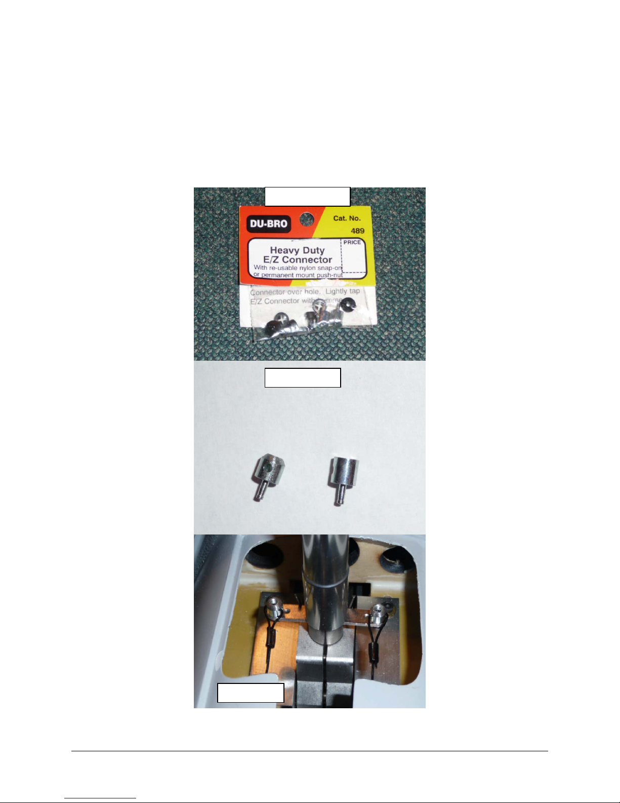
To ensure tangle free operation of the pull-pull cable system Du-Bro heavy duty E/Z
connectors (see photo 67) were used to hold the steering cables to the tiller arm. The
advantage of this setup is it allows the cables to rotate easily when the nose wheel is
retracted.
Modify the E/Z connector by chucking it up in a drill or Dremel tool to spin it, then while it is
spinning sand it on a belt sander or a file to add the 45 degree chamfer on the top. The
chamfer is needed to ensure the cable loop does not get caught on the edge, See photo 68
for details.
Fasten the E/Z connector to the tiller arm using the supplied clips, the E/Z connectors
should be inserted from the bottom of the tiller, see photo 69.
Photo 67
Photo 68
Photo 69
34
Page 35
Check for clearance
Photo 70
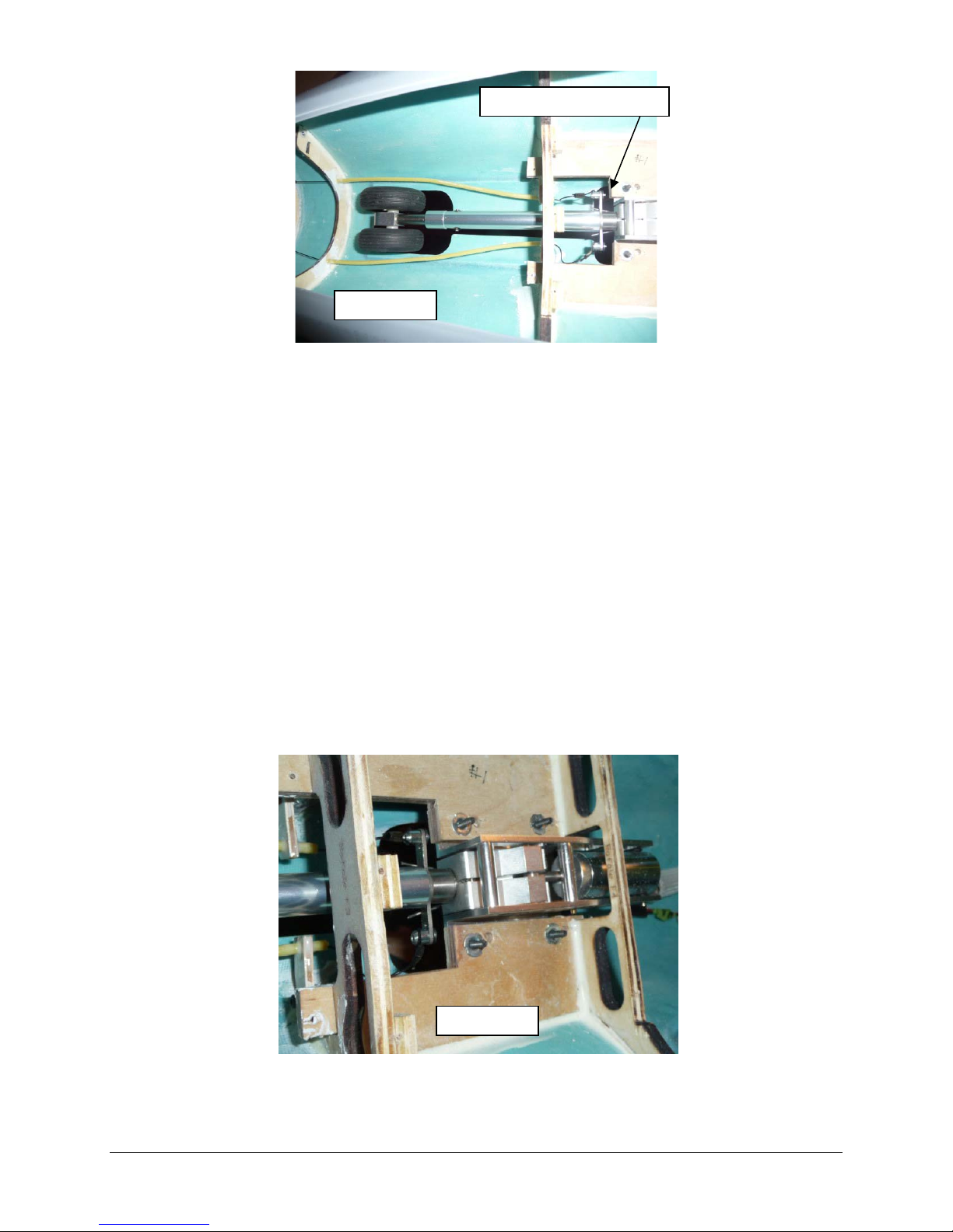
Position the nose retract unit into the retract plate from the bottom. The front of the retract
unit should be positioned as shown in photo 70, make sure to check the tiller arm clearance
between the mount, this can be done by moving the retract from up to down position by
hand.
Working carefully to make sure the retract unit stays in this position and aligned equally to
either side of the gear opening, drill one of the holes closest to the forward former. Insert a
bolt into the hole to hold this position.
Proceed to drill the other three holes, making sure to maintain alignment of the gear. Insert
a bolt in each hole as it is drilled.
When all four holes are drilled and you are satisfied with the alignment, remove the retract
unit.
4-40 Allen head bolts and blind nuts were used for this build; drill out each hole to be large
enough for the blind nut. Insert these from the top and snug them down with one of the
bolts. Apply a little CA to the back of the blind nuts sparingly to hold them in place, see
photo 71.
Reinsert the retract unit and bolt in place. Loctite® bolts to blind nuts.
Fabricate two plywood cable guides that will be mounted to the front bulkhead as shown in
photo 72. Route steering cables using an inner section of a Nyrod for a cable guide.
Finial connections to steering servo will be covered in section 10.
Photo 71
35
Page 36
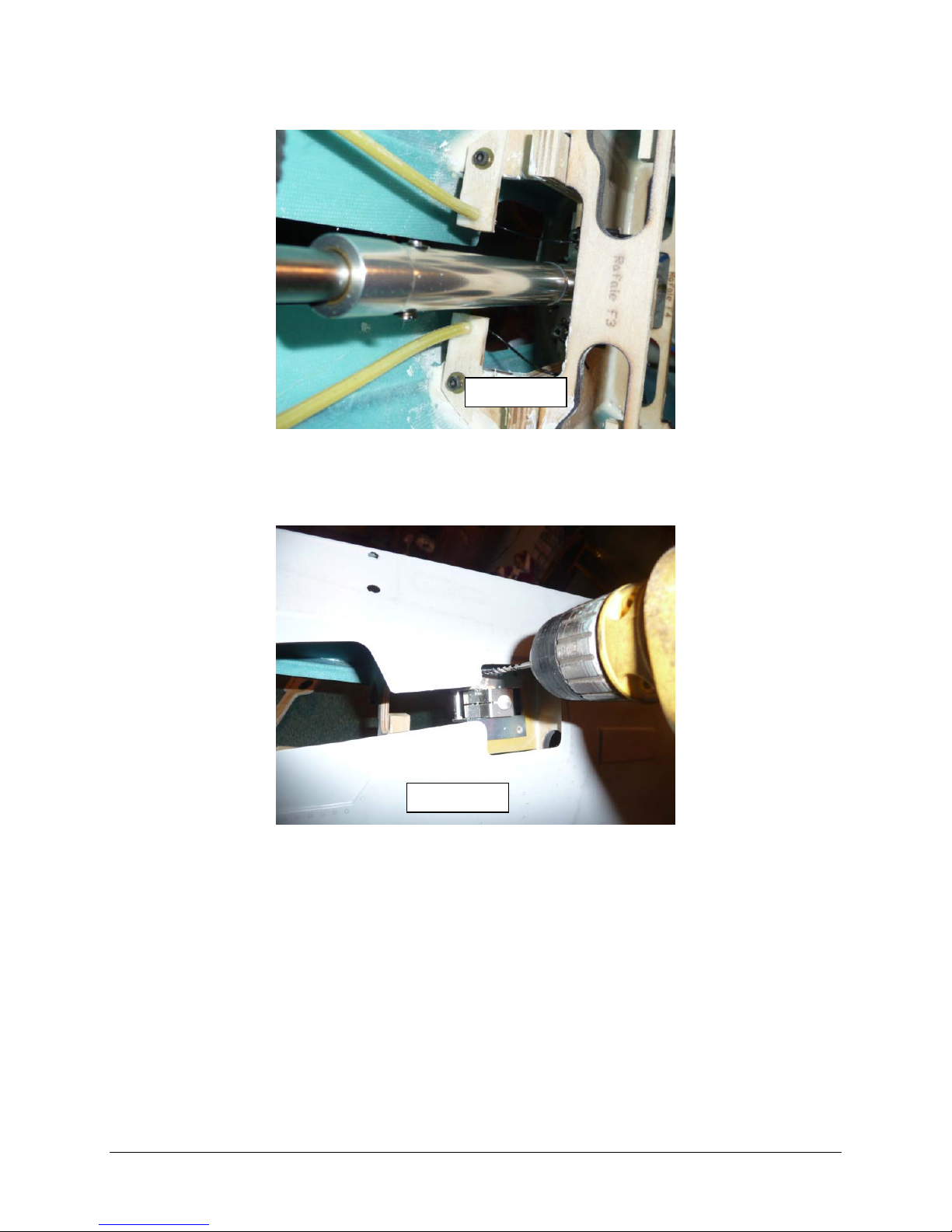
Step 8: Main Landing Gear
Photo 72
Install airlines on the retract units.
Check for air leaks and smooth operation of the retracts with a hand pump as done in
section 7, see photo 66.
Install main struts into the door retract cylinders.
Working carefully to make sure the retract unit stays in this position and aligned equally to
either side of the gear opening, drill one of the holes closest to the forward former. Insert a
bolt into the hole to hold this position see photo 73.
Proceed to drill the other three holes, making sure to maintain alignment of the gear. Insert
a bolt in each hole as it is drilled.
Photo 73
36
Page 37

When all four holes are drilled and you are satisfied with the alignment, remove the retract
unit.
4-40 Allen head bolts and blind nuts were used for this build; drill out each hole to be large
enough for the blind nut. Insert these from the top and snug them down with one of the
bolts. Apply a little CA to the back of the blind nuts sparingly to hold them in place after the
blind nut installation is complete reinsert the retract unit and bolt in place, Loctite® bolts into
blind nuts.
Step 9: Gear Doors Airline connections
There are seven operating gear doors on the Rafale, three nose gear doors and four main gear
doors.
These doors will be identified as follows:
Single front main nose door – this door will close after gear deployment
Two small nose doors – these doors will remain open after gear deployment
Two front main gear doors in front of the mains - these doors will close after gear deployment
Two smaller main doors – these doors will remain open after gear deployment
There will be four primary door connections required: (1) Single front main nose door & Two
front main gear doors open (2) Single front main nose door & Two front main gear doors closed
(3) Two small nose doors & Two smaller main doors open (4) Two small nose doors & Two
smaller main doors closed.
Operation of the gear door cylinders is up to the builder’s discretion as many options exist, for
this model it was decided to operate the door system with two servo driven two-way valves and
a electronic gear door sequencer.
This will be an overview of the process involved. The first valve will control the opening and
closing of the Single front main nose door & two front main gear doors. The second valve will
control the open and closing of the two small nose doors & two smaller main doors. It is
recommended to use different colored air line to help identify the function of the air circuit.
Air line routing should be neat and kept as short as possible, when connecting using a Y
connection to feed two cylinders, the line length of each path of the Y should be kept equal.
The air lines should be bundled using ty-raps (wire ties) however care should be taken as not to
tighten the wire ties too much as to cause a restriction. See photo 74 for a typical example.
The vale placement and connection will be covered in the equipment tray section
Standard Air Kit Contents:
79” (200cm) Blue Air Line
79” (200cm) Red Air Line
79” (200cm) White Air Line
79” (200cm) Yellow Air Line
3 Three port valves (Gear & Doors)
1 One Port Valve (Brakes)
2 Air Tanks
1 Fill Fitting
6 Three port Y’s
4 four port Tees
4 Disconnects
37
Page 38
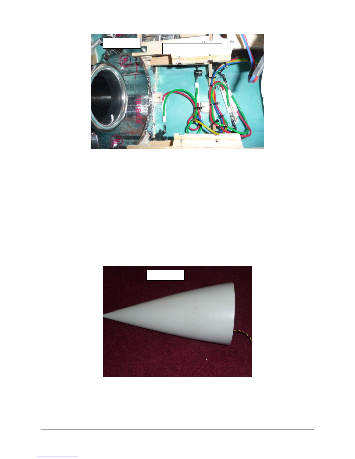
A
Photo 74
irline Connections
Step 10: Nose Gear Steering & Joining the Fuselage Nose Section
Installation of equipment is up to the builder’s discretion as many options exist. The factory
supplied position of the steering servo was in the front equipment tray; however this location
proved to increase the amount of servo torque required for steering, it was decided to fabricate
a new servo mount to position the steering cables in a straight line from the tiller arm, The new
mount was placed into the nose section, see photo 75.
Fabricate the servo mount/battery holder as per photos 76 through 80.
Inspect all the nose mounting holes in the fuselage to insure they are free from debris. Try
the bolts and make sure they all thread easily.
Position the nose section and using the supplied bolts and washers, bolt the two main
bulkheads together.
Photo 75
38
Page 39
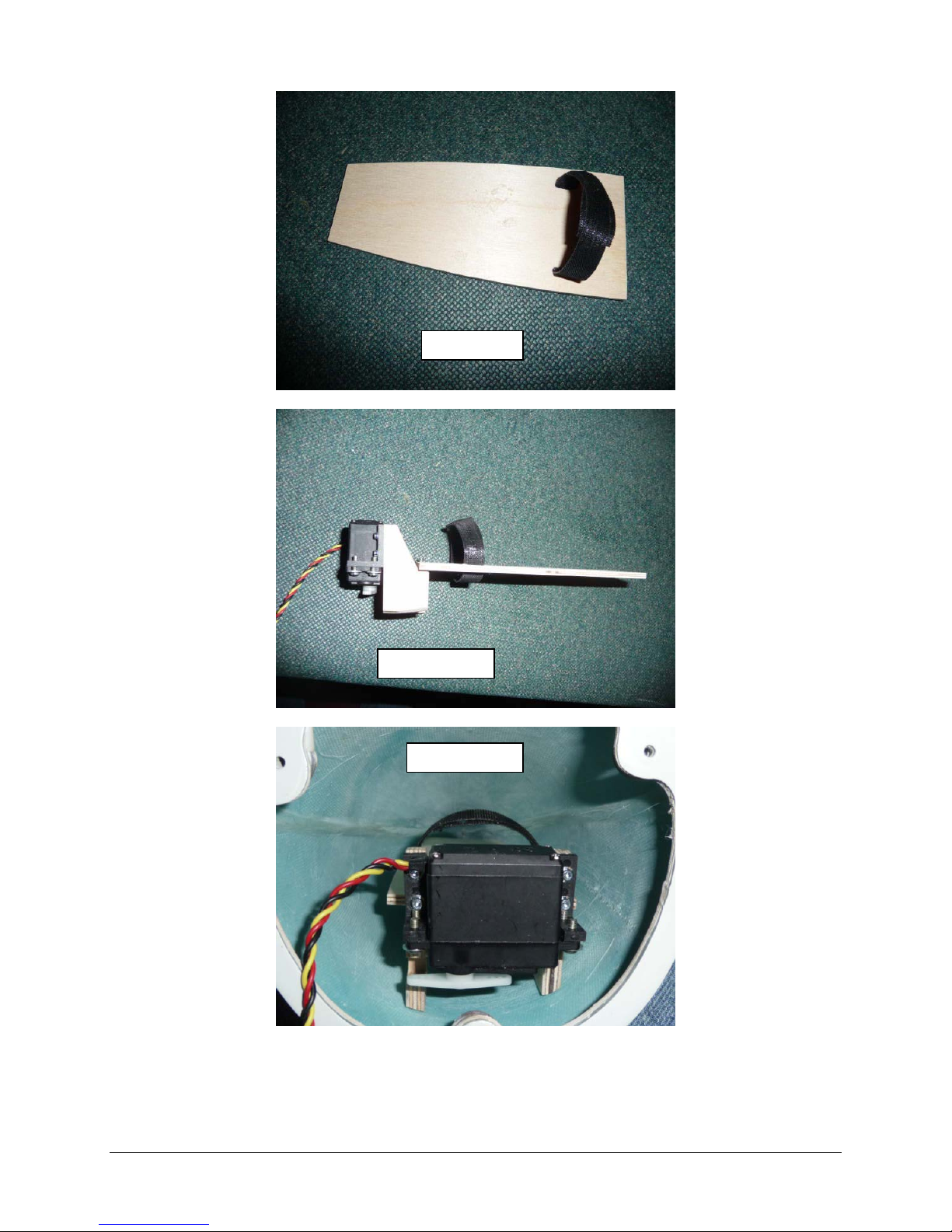
Photo 76
Photo 77
Photo 78
39
Page 40
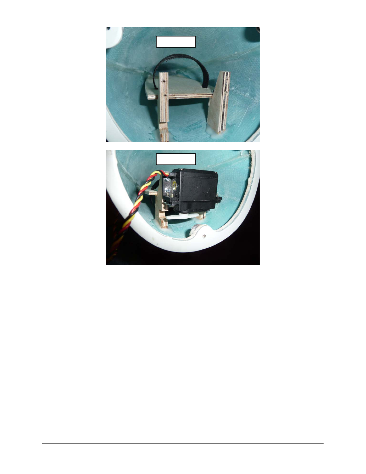
Photo 79
Photo 80
40
Page 41
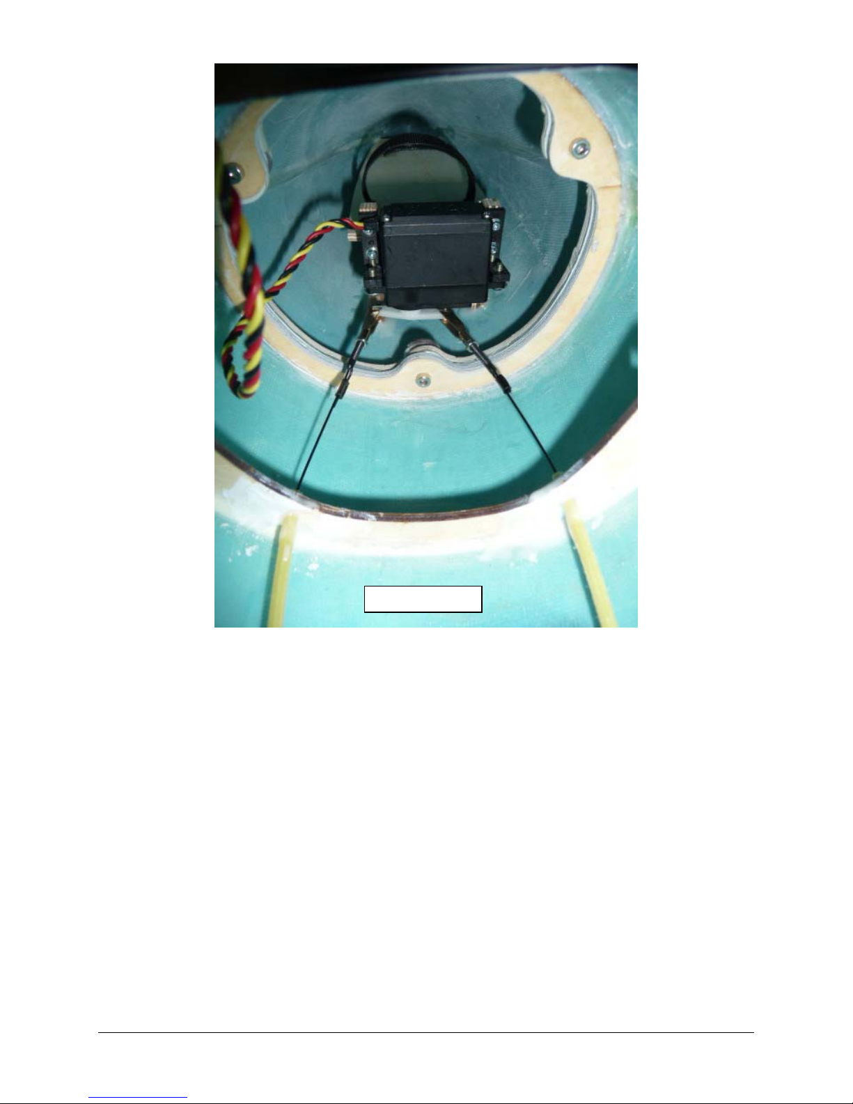
Photo 81
Make the final steering cable connections as shown in photo 81.
Step 11: Component Board
There are a vast amount of possibilities for mounting equipment into your airframe so the
following is one suggested method. Remember to allow room for the cockpit tubs to sit into the
airframe without interference from tall components on the component board. In the model use
for the production of this manual the receiver, ECU and gear sequencer were mounted on the
fuselage sides next to the tray as the Rafale has many open areas that are well suited for this
equipment. By doing so much of the wiring remains undisturbed if a tray needs to be removed
for other servicing.
The pneumatic retract system in the model is operated by three valves. The first two way valve
controls gear up and gear down, the second two way valve controls the gear doors that stay
open with retracts down, and the third two way valve controls the doors that close with the gear
down. All three servos are connected to an electronic sequencer that is connected to the
retract channel of your receiver.
A suggested layout of components is shown in photo 82. This arrangement allows easy access,
provides good separation between the turbine and receiver electronics and sits low enough for
the cockpit to easily fit on top. A profession looking installation may be had by creating a
graphic overlay on the component boards, see photo 83.
41
Page 42
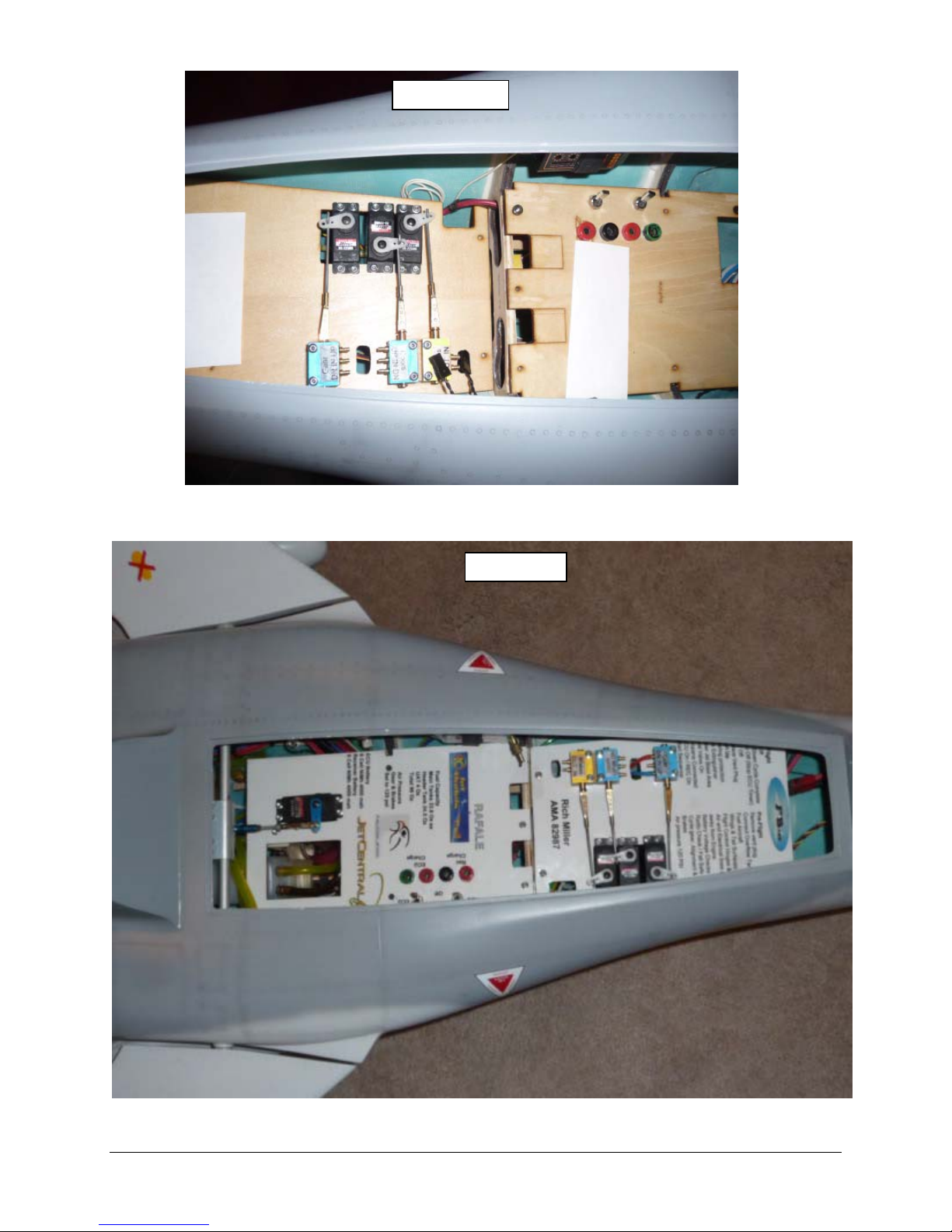
Photo 82
Photo 83
42
Page 43
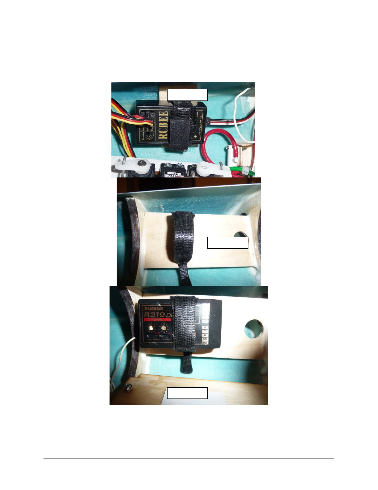
Addition component locations for ancillary devices such as the gear door sequencer, receiver,
voltage regulator and ECU to name a few can be done using mounting plates glued to the
fuselage in positions where space allows. Slots cut into the plates allow for the use of Velcro
strapping to hold the components, see photos 84 through 87.
Photo 84
Photo 86
Photo 85
43
Page 44
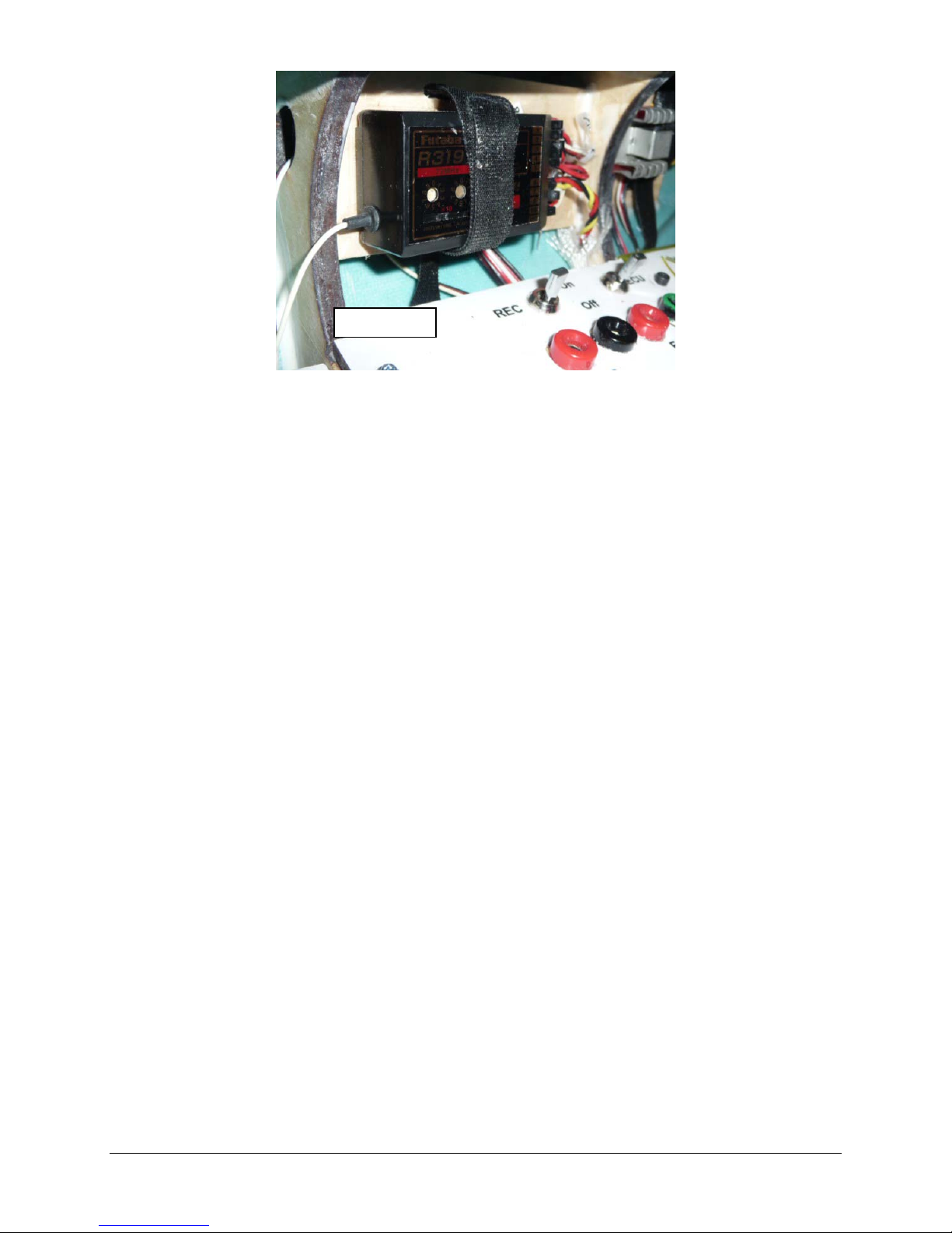
Photo 87
For areas under the front component tray make sure to keep the clear of wires and airlines
for retraction of the steering servo. The nose wheels will fit right up against the bottom of
the component board when retracted, so it is recommended you have nothing extending
below the board in this area.
Now is a good time to complete installation of all servo extensions, airlines and turbine
electronics through the fuselage.
Step 12: Canard
Servo placement options are up to the builder, for the model depicted in this manual the canard
servo was placed in a cutout that was created on the rear equipment tray; additional plywood
was used to double the thickness of the tray in the area of the servo cut out.
Additionally it was noted that the stock tray position was a bit low so a cross member made
from ¼” plywood was added across the center bulkhead to raise the tray height. Two 4-40 blind
nuts were installed on the cross brace before gluing to the bulkhead to facilitate the tray
mounting, see photo 90.
Even with the rear of the tray doubled it was noted that the tray was still able to flex; to stiffen
the tray a plywood standoff (rear tray brace) was fabricated for the back of the tray. The brace
was mounted to the fuselage via wood screws to a block that was glued to the bottom of the
fuselage, this was done to facilitate to allow removal for tank maintenance, see photos 90 & 91,
the tray was mounted to the standoff with a wood screw.
Install the canards by placing the supplied Nylon washer on each shaft; apply grease such
as “Super Lube” to the bushings in the fuselage see photo 88.
Insert the Canard into the bushings, and then position the Canard Control horn as shown in
photo 89; the clamping bolts should face the main tank to ensure maximum clearance for
the control horn.
Tighten clamping bolts ensuring that when both Canards are level the horn is pointing
straight down towards the bottom of the model.
Canard settings will be covered ins section 19.
44
Page 45

Photo 88
Photo 89
45
Page 46
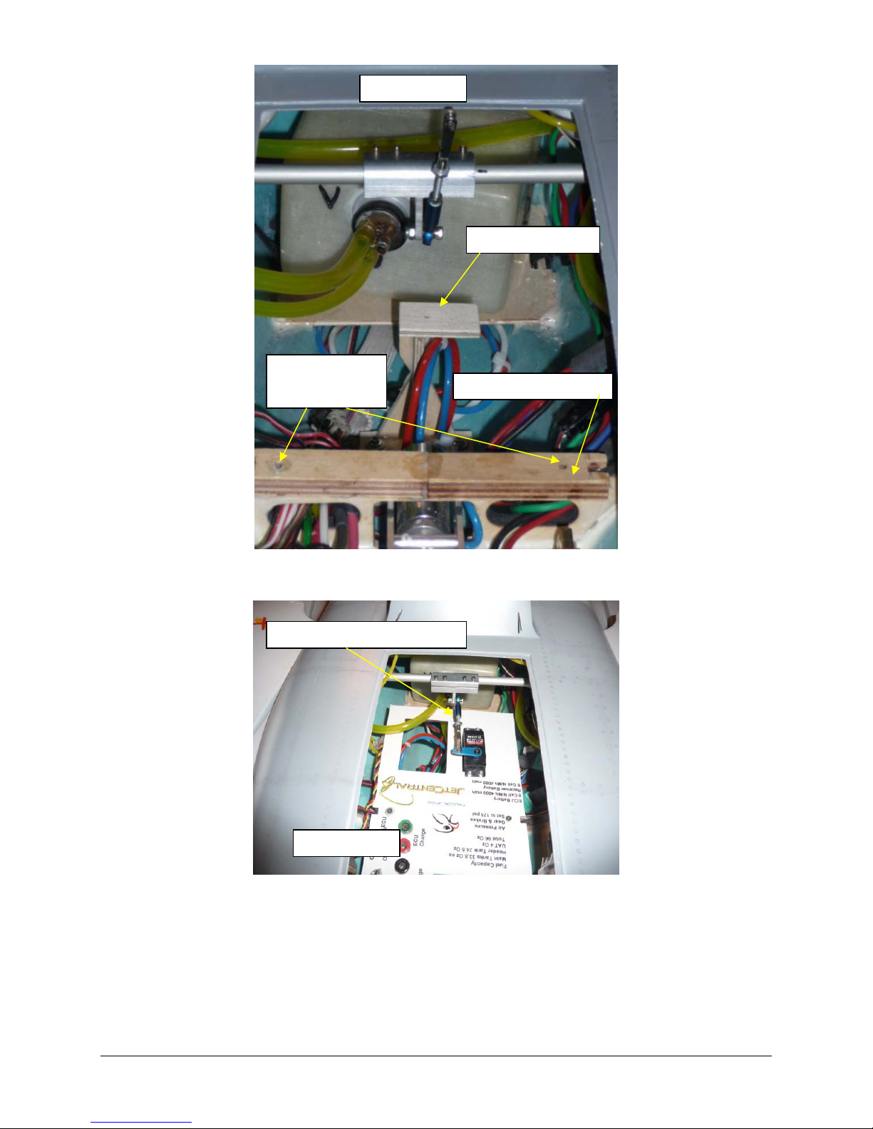
Photo 90
Rear Tray Brace
4-40 Blind Nuts on
bottom of cross
brace
Front Mount Doubler
Rear Tray Mounting Screw
Photo 91
46
Page 47
Step 13: Engine Rails, Bypass and Pipe
Clean the fuselage thoroughly before installing the engine. If you need to trim the intake for
engine clearance, use a vacuum while you work. This will reduce the chance of having a
foreign object finding its way into your engine.
It is the builders choice as to use the supplied full bypass for your installation; however if you
choose not to use the full bypass then it is suggested to use at least the bottom half of the
bypass, this will create a barrier between the hot parts of the turbine and the pneumatic line
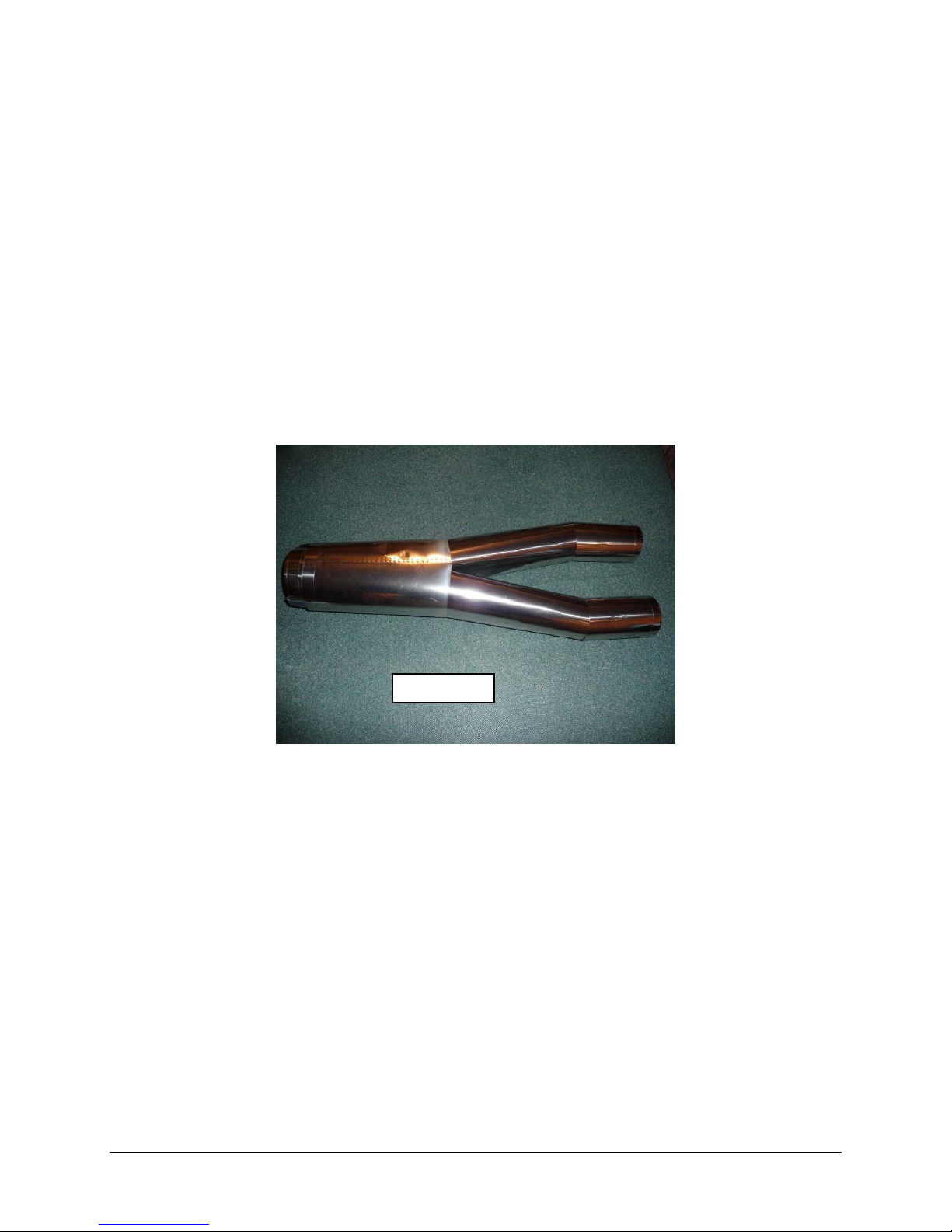
used in your aircraft.
Drill two holes on each side of the pipe mounting tabs. The first should be just in front of the
pipe mouth, the other approximately 50 mm further forward.
The tabs are positioned just above the centerline of the pipe and this is the top. Insert the
pipe into the fuselage and position the aft end about 5 mm from the end of the exhaust
cones.
Photo 92
Place the lower bypass on the engine mounting rails. Slip the pipe forward over the aft end
of the bypass. You may need to slightly trim the lower former a bit to allow the bypass to
move far enough aft to keep the rear of the pipes in position.
Position your engine on the mounting rails. Set the gap between the rear of the exhaust
cone and the mouth of the pipe to manufacturer’s specifications. This is usually around 20
mm. You may need to trim some material off the intakes to allow the engine to sit far
enough forward.
If required, marks the bypass for the positions of the engine mounting tabs and trim away
material such that the engine exhaust is centered on the pipe. Shims may be required
under the front engine mounting tab to insure that the angle of the engine is on line with the
angle of thrust line of the pipe.
When you are satisfied, bolt the engine to the side frames; you can use appropriately sized
wood screws or install blind nuts. If using wood screws install the screws and then remove,
then coat the thread holes with thin CA. This will harden the wood around the screw holes
themselves. Permanently reinstall the engine mounting screws.
Drill and secure the bypass to the engine mounting rails with four wood screws.
Finally, drill the rear of the bypass for the pipe mounting straps and bolt in place. The heads
of the bolts should be on the inside of the bypass.
47
Page 48
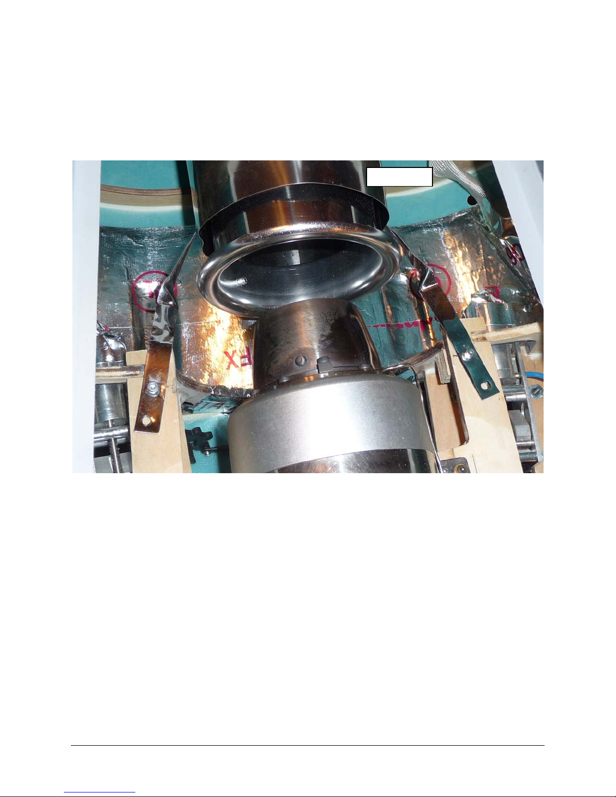
Connect fuel, gas and electrical lines up to the turbine following engine manufacturer’s
recommendations.
Bell mouth
If the Bypass is not used then you will need to purchase a bell mouth that will be used to
hold the shape of the pipe inlet, attach as per the manufacturers recommendations, see
photo 93
Photo 93
Step 14: Engine Accessories
For ease of maintenance it is recommended that the major engine fuel handling components
(i.e. pump, & solenoids) should be mounted on a removable plywood plate. Also the ECU
should be mounted on its own plate see photos
48
Page 49
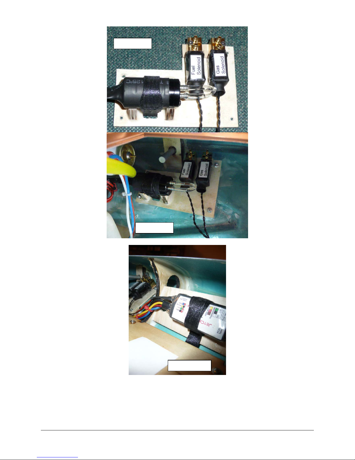
Photo 94
Photo 95
Photo 96
49
Page 50
Step 15: Cockpit
The cockpit tubs come pre-trimmed and painted with a gloss black finish and should simply
drop into place; if desired you can paint the tubs with flat black or grey.
The canopy also comes pre-fit at the factory and should be latched in place.
You can glue the tubs to the canopy if desired.
Step 16: Tail Accessories
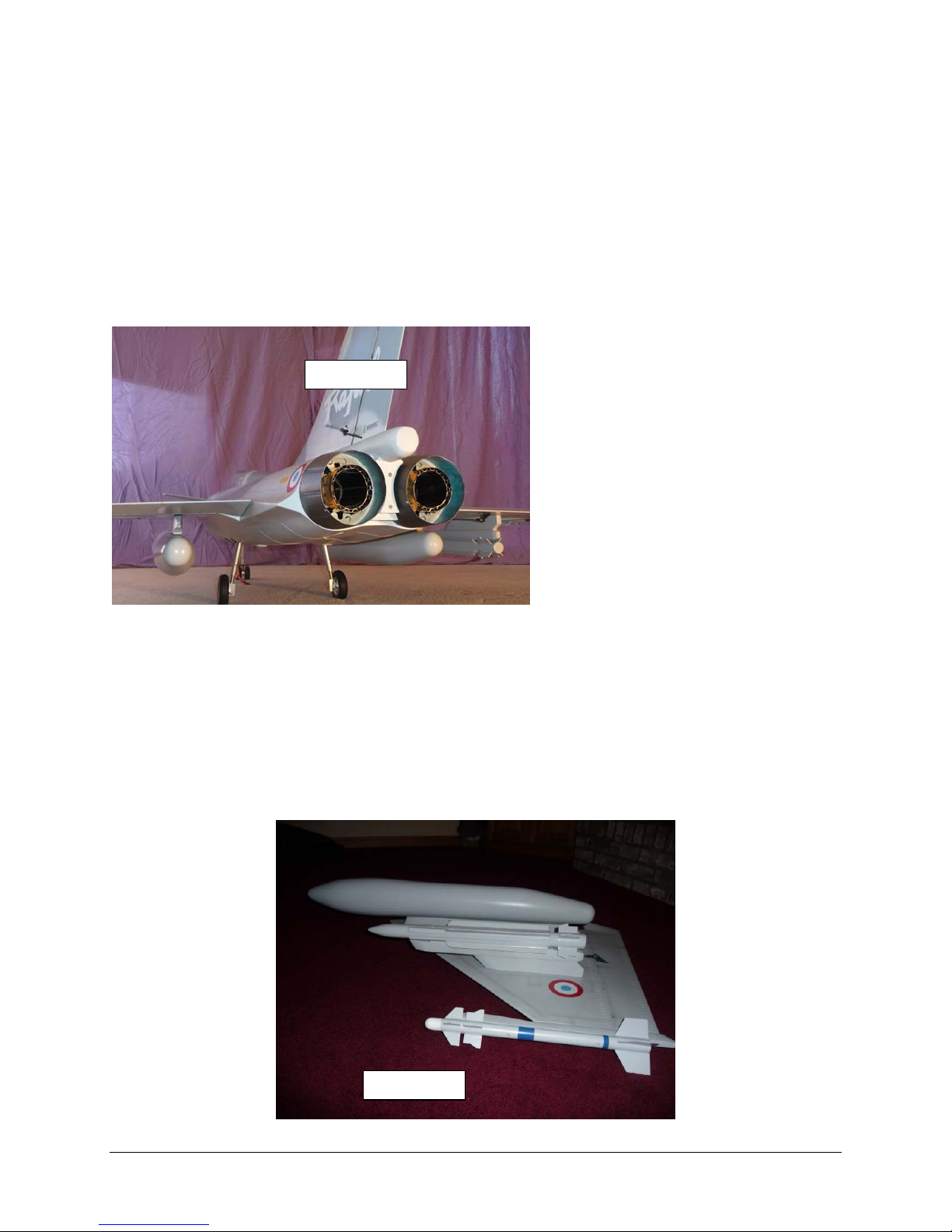
Bolt the exhaust cones to the aft firewall.
Bolt the center section to the aft fuselage.
Reference photo 97, this completes the aft fuselage work.
Photo 97
Step 17: Ordinance
The mounting locations for the ordinance are predrilled from the factory.
Using the supplied hardware to mount the rails to the wing section, it is suggested to use
Goop™ between the rails / pylons and the wing, this provides for a flexible but strong joint.
Photo 98 shows the locations of the ordinance.
Photo 98
50
Page 51
Step 18: Radio Programming
The prototype was set up utilizing 8 channels as follows using a Futaba 9C, many radio system
and option exist, it is up to the builder’s discretion to pick the equipment that best fits the their
needs:
Ch 1 Elevon (Elevon mix enabled)
CH 2 Elevon (Elevon mix enabled)
CH 3 Throttle
CH 4 Rudder
CH 5 Retracts connected to RC Bee Gear sequencer (i.e. Gear servo, Door 1 Servo and
Door 2 servo)
CH 6 Brakes (Mixed with CH 2, activate on down command) also Mixed with CH 5; enabled
with Retract Down only
CH 7 Aux 1 Canard (Mixed with CH 2); the VR(B) trim knob was used for trim, this feature
required a proportional mix of AUX 1 to AUX 1 (all five points programmed to -100%) to limit
the travel of the canard from level to up attitude on the trim knob VB(B) or slider control
VR(D).
Note: The canard trim control could be programmed to one of the side mounted slider
controls such as VR(D) for ease of access to be used to experiment with high AOA landings.
CH 8 Aux 2 Nose gear steering (Mixed with CH 4); VR(A) was used for trim also Mixed with
CH 5; this channel is enabled with Retract Down only.
Step 19: CG and Control Throws
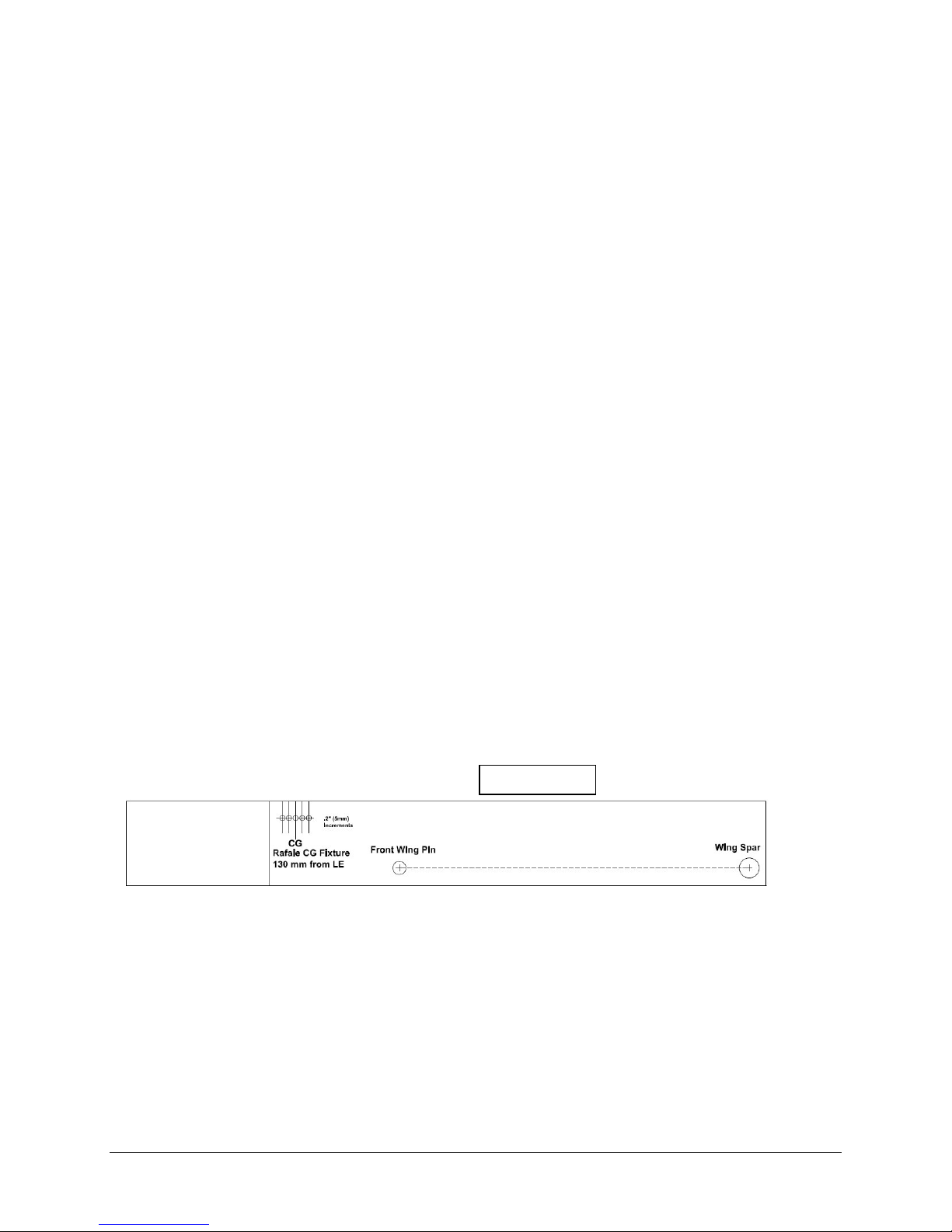
Set the Center of Gravity for 5 1/16” (130 mm) from of the leading edge of the wing panel at the
root. The CG should be determined with the UAT filled with fuel and with the gear in the
extended position. Battery positioning should be enough to achieve the correct CG location.
Note: To simplify the process of determining the CG the author created two plywood fixtures
that can be inserted between the wing panels and the fuselage, see photo 99. The Airframe
then can be lifted with a strap on the GC point to allow easy adjustments, see photo 100.
Photo 99
51
Page 52
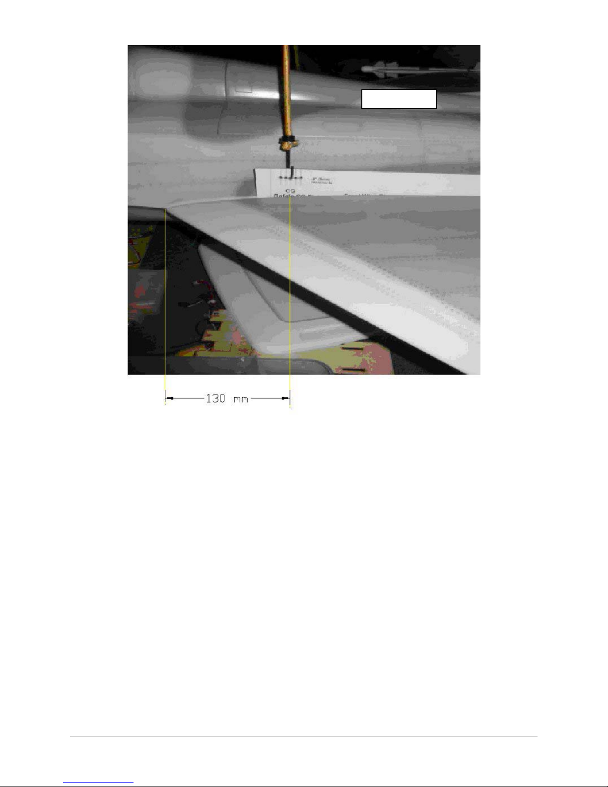
Photo 100
Elevon (Elevator Function) should be set to 18 mm up/down as measured from the center
line of the missile rail.
Elevon (Aileron Function) should be set to 8 mm up/down for high rate and 3mm up/down
for low rate. The Rafale require reflex to be programmed, i.e. the bottom edge of the Elevon
should be set to be slightly below the bottom edge of the missile rail (if installed) or wing tip.
When looking from the rear of the model it will have the appearance of having down elevator
applied. Aileron throw should be in low rate the first flight. Adjust this in subsequent flights
to suit your flying style. The Rafale has a tremendous amount of aileron authority and it
requires very little control movement to give impressive roll rates.
Canard throw will be in the 25 mm up and 12 mm down
Rudder throw will be in the 28 mm range in both directions
Nose Steering should be set to the minimal movement to avoid over steer during take off
and landings
52
Page 53

Maintenance Tips:
Inspect the door cylinder bolts and hinges each time you mount the wing.
When inverting the aircraft, put a short piece of fuel tube with a plug on the drain fitting.
Cycle the gears before each flying session, checking for binding and proper door operation.
Check the struts for play, indicating the clamping set screw needs to be tightened, verify toe
in on main wheels for reliable tracking.
Check all hinged surfaces; i.e. pull on them before each flying session
Check for proper radio operation, slowly cycle all surfaces with the transmitter making sure
they are moving in the correct direction and proper deflection(Note: it is easy to lose a
model due to a simple mistake of selecting the wrong model memory in the transmitter)
Check all linkages, use keepers on the quick links
Check Canard clamp fitting for tightness
Check Vertical fin mounting for tightness
Check Fuel system for leaks
Check all batteries before each flight, setup a routine maintained schedule on your batteries
making sure that they cycle properly for capacity.
Note do not charge LiPo batteries while installed in the airframe.
53
Page 54
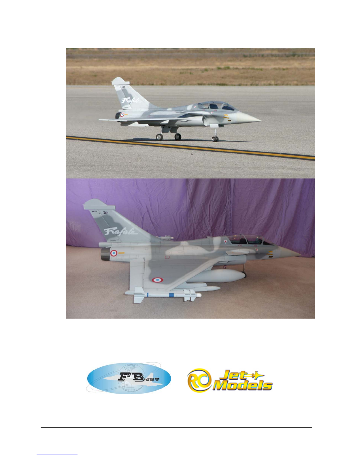
Congratulations, you have completed construction of your Fei Bao Rafale
54
 Loading...