

Page 1

FEI BAO F-16 1/6TH
FB Jets/ Feibao
F16 Falcon Assembly Manual
Written by Tyson Dodd in Collaboration with Fei Bao Jets
Page 2

FEI BAO F-16 1/6TH
DISCLAIMER
THIS IS NOT A TOY. This is a high-performance miniature aircraft, capable of high speeds and
damage to life, limb, and property. The manufacturer and its distributors cannot control how you
assemble this model, what equipment you use to fit it out, or how you fly it, and can assume no
liability whatsoever for any damages that may occur when you fly your aircraft. By assembling this
model, you are agreeing to indemnify and hold blameless the manufacturer and/or his agents
from any and all torts and liability associated with the use of this product. Please inspect all parts
before beginning assembly.
If any parts appear to be suspect, contact your dealer or the manufacturer for repair or
replacement BEFORE you begin. Once you have assembled the aircraft, you are the pilot in
command and assume any and all responsibility for the use of the model and any damages that
might occur by flying or attempting to fly this aircraft. R/C model jets require a high level of skill in
both their assembly and their flying. If you do not feel confident in either your building or flying skills,
PLEASE seek assistance from more experienced modellers. It is a wise idea, no matter what level of
skills you possess, to have a second experienced modeller go over your installation after assembly.
A second set of eyes may spot a problem you have missed. If you have not flown a model like this
before, it is HIGHLY recommended that you get an experienced turbine pilot to do your maiden
flight. Very often, the first few seconds of a maiden flight are critical until the aircraft is trimmed out,
and having an experienced pilot at the controls can make the difference between a wrecked
aircraft and once that enjoys many hundreds of flights. Be sure to select a suitable field for
flying...take the time to find a large paved runway if at all possible, especially for test flights, until
you feel comfortable getting the aircraft in and out of smaller grass fields.
Before you begin keep this in mind as you proceed:
Look at EVERY assembly step you finish, and ask yourself:
"Is this going to crash my airplane?" A chain is only as strong as its weakest link, and this is a high
performance aircraft that will be very intolerant of sloppy assembly techniques. Even the smallest
component is important and can cause the loss of your airplane, so take the time to do things right.
Or redo them if they are wrong. Careful work will result in a long lasting plane that gives you years
of pleasure, one loose component could result in the complete loss of the aircraft and all the
components inside it, and someone can even get hurt. So pause every once in a while when
building it and double-check your workmanship.
Page 3

FEI BAO F-16 1/6TH
Introduction
You have chosen a model that represents the pinnacle of ARF technology and factory testing.
While there is not a lot of building to do in comparison to traditional modelling techniques, there is
enough to keep you busy for a few evenings. Even if you have assembled maybe other ARF jets,
we highly recommend following our assembly sequence and procedures anyway. Chances are it
will save you a lot of time or having to redo sections given some specific sequences and will
prevent you from running down dead ends, and perhaps remind you of a few small things that
might end up saving your aircraft.
I have assembled this manual to try and keep things moving wile you are awaiting for glue to dry
before you can proceed to the next step. Just because the model is almost completely built does
not mean you can rush through the final assembly. This is still an airframe that required minor
assembly and general complete building techniques. You need to employ fine craftsmanship
every step of the way, turbine models are critical. Keep this in mind with everything you do, every
part you install...look at the work you just did, evaluate it critically, and ask yourself "is this going to
potentially crash my airplane? I continually ask myself during the building of any jet and if there is
any doubt about the work you have done, please back up, and re-do it properly. We have
included as many pictures as possible to give you an idea of the ultimate location of components
within the airframe you minimise any balance work for perfect CG.
Adhesives
The correct adhesive to use for all procedures is Loctite Hysol 9462. This is a very strong white epoxy
that is thixotropic. "Thixotropic" means it does not run at all, but stays only where you put it. It is
infinitely superior to regular epoxy, even slow-setting epoxy, for our purposes, because of this
characteristic. Regular epoxy will run downhill with gravity as it dries, taking it away from where it is
supposed to be. A good example is in the hinges...using regular epoxy, a good portion of the glue
will migrate down away from the hinge into the inside of the wing as it dries, and you won't even
know it is happening. Hysol stays where you put it. The downside of Hysol is it takes overnight to dry
properly, but we have tried to arrange things to keep you busy while waiting for glue to dry.
We also highly recommend that you only use a proper Hysol dispensing gun, and only the longtype mixing nozzles. The short nozzles do not mix this glue enough, and only a thin nozzle and gun
will let you fill the hinge and control horn holes properly with glue, you can't do it mixing your Hysol
on a flat surface and trying to get the glue in the proper place by a brush or stick.
You can buy a complete Hysol setup with a gun, nozzles, and two cartridges of glue from your
dealer for approximately $60. Consider it a great investment, the glue is the best you can use to
finish you kits from FB Jets.
One cartridge should be plenty to assemble your F16, however depending on how you prefer your
setup, it is a good idea to have spare available.
Working with pneumatic systems F16 uses pneumatic brakes and retracts. If you follow a few tips,
you should have very reliable, leak-free operation. Neatness counts. All airlines should be secured
to the airframe to keep them from flopping around or getting kinked. Use tie wraps for this.
The other very important thing is to cut off the end of each airline dead square before installing it
on the nipple. This is VITAL. You can either purchase a professional tubing cutter from your dealer
(they are approximately $10), or you can make up a little jig to hold the airline and keep a sharp,
new razor blade perfectly upright as you cut. Either one works, just ensure that all ends of all airlines
are cut off dead square. Make sure all airlines are pushed ALL THE WAY onto their nipples. They
should not need to be secured otherwise, but you can add fine wire safety wraps if you like. Make
sure all left and right matching airlines are the same length, particularly the brake lines, or you will
Page 4

FEI BAO F-16 1/6TH
get uneven retraction or braking action. It's worth taking the time to get everything pneumatic
right the first time, as having your landing gear fail to retract is not THAT bad, but having it fail to
deploy can really ruin you day and the paint on the bottom of your model.
Construction
Preliminary steps
The following setup are recommended by FB jets for all kits that they manufacture and request the
modeller to conduct these quick and simple steps to not only make your build easier, but cleaner.
• Clean and inspect all parts. Inventory them against the parts list at the end of the manual
and notify the kit supplier of any missing components as soon as possible.
• If the paint scheme you have selected is glossy, it is recommended that you apply a coat
of wax. This will help resist dirt, stains and fingerprints during construction, and will provide
some limited protection against errant glue.
• Vacuum out the remnants of packing materials that remain in the fuselage.
While the kit is comprehensive, there are additional parts required, as follows:
• Recommended Servo List (JR)
• Elevators: (2) 8611a
• Aileron: (2) 8611a
• Rudder: (1) 8411
• Nose Steering: (1) 8611a
• Retracts: depends on retract and door solution selected (a 5 function valve can be utilised
on this aircraft)
• Brakes: (1) 351 or equivalent, or an electronic brake unit in a combination unit
• The abovementioned servo list is idea, you will note 8911 have been used through this
model though as this is what I had available at the time.
Other Parts
• Intairco UAT
• Fuel tank vent bulkhead fitting
• Festo fuel shutoff valve *2
• Wire twist tie (optional)
• Blue Loctite
• Red Loctite
• Glues: Thin CA, 5 minute epoxy, 30 minute epoxy, Hysol,
• Electronic gear sequencer, I have used a 5 function unit for the retracts, doors and brakes
• Or Brake valve
• Batteries, regulator and switch
• Matchboxes, Powerbox, Smartfly EQ10 or Spectrum Power Safe (I have utilised AR9200 for
this build)
• Servo extensions (length may vary, depending on receiver placement)
General Construction Notes:
The order of construction may be changed to suit your personal preference; however, the model is
more easily worked in a tight space if work is completed on each fuselage section before they are
joined. The tail surfaces must be attached before the aft fuse is joined to the forward fuse, as the
pipe must be in place during this step and it blocks access for wiring.
The retract system doors operate in two different ways. The main gear doors and the large nose
gear door open, the landing gear cycle either up or down, and the doors close again. For this
Page 5

FEI BAO F-16 1/6TH
action, you will need two separate valves with a sequencer or precision dual function units, I have
used the Fly Eagle 5 function unit for this build to conserve space,
You will likely need to match twin rudder and twin elevator servos for this model
This may be accomplished with servo reversing “Y” harnesses, JR Matchboxes, the Smartfly EQ10, a
Champion Powerbox or equivalent. I have utilised a JR Match box for simplicity in this build.
Step 1: Check Forward Fuselage
• Remove the fuel tanks from the fuselage.
• Also remove the forward component boards. Now would be a good time to put a coat of
paint on these parts if you would like to protect the wood surfaces.
• Vacuum and thoroughly clean the fuselage completely including light sanding on the
mould joins to ensure there are no fibreglass burrs. These are painful if they “bite” you
during building and could potentially cause an air leak to tubing or damages to servo wires
etc.
• If the nose gear was installed at the factory with bolts and lock washers, check these for
security now. I also recommend checking the functioning of the nose gear now with a
hand pump. Make sure the rotation at extension and retraction of the nose wheel is
smooth before final installation. The Nose steering however needs to be set up before final
installation.
• Once the nose gear and servo is done, install but place a very small dab of thin CA into the
screw hole first. A small toothpick helps limit the amount of glue applied if you don’t have
limiting tip on you CA bottle.
• Check the nuts and connections of the gear doors. If required place a small amount of
thick CA on the nuts to secure.
• Repeat this step for the three nuts that attach the door cylinders to their respective
mounting blocks.
• Check all door hinges for security.
• Newer kits have carbon fibre reinforcement in the nose section.
• Run a bead of hysol down the sides of the three nose formers to reinforce the joint with the
fuselage side if you feel necessary.
Step 2: Prepping the Fuel System
Disassemble and inspect the tank cap hardware. The process used to cut the tubes may leave
behind a rim that constricts fuel flow and could result in excess tank pressure and leakage. Given
the use of three tanks be sure to pressure check and fill prior to installation in your model. Every
care is taken at construction, however sometimes a leak may occur. Checking this prior to
installation will save cleaning and time for pulling the tanks back out.
• Loosen the Philips head screw and remove the stopper assembly from the tank.
• Use a small, round Perma-Grit rat tail file or a knife to remove the excess metal. You will
need to inspect the ends of all tubes.
• When finished, make sure to blow out the metal fragments and clean up any sharp edges.
• While the components are apart, check the Tygon pickup line for equal lengths in both
saddle tanks. They should be long enough to reach the back of the tanks without being so
long as to restrict their ability to move to the top of the tank when the aircraft is inverted.
Allow a small amount of play to allow the tubes to stretch slightly over time.
• You should also notch the vent tube with a small file to provide for continued air flow should
the tube come into contact with the top of the tank.
• Make sure the bends to the vent tubes applied at the factory have not restricted airflow to
any significant extent. Also, check the Tygon for any nicks or cuts and secure to the tubing
with wire ties before re-assembly.
• Reassemble and mark the tank for vent and fuel for later reference.
Page 6
FEI BAO F-16 1/6TH
• Once the tanks are back together, they should be leak checked before installation in the
aircraft. Connect extra lengths of fuel tubing to the fuel and vent lines and submerge the
tank in water. Pinch off one line and gently pressurize the tank by blowing into the other,
looking for signs of air bubbles. If the tank shows evidence of air leakage around the vent
cap, tighten the Philips head screw and check again. If you have a stubborn leak, you can
re-tap the inner plate for a slightly larger 6/32 cap head bolt.
Step 3: Tank Installation
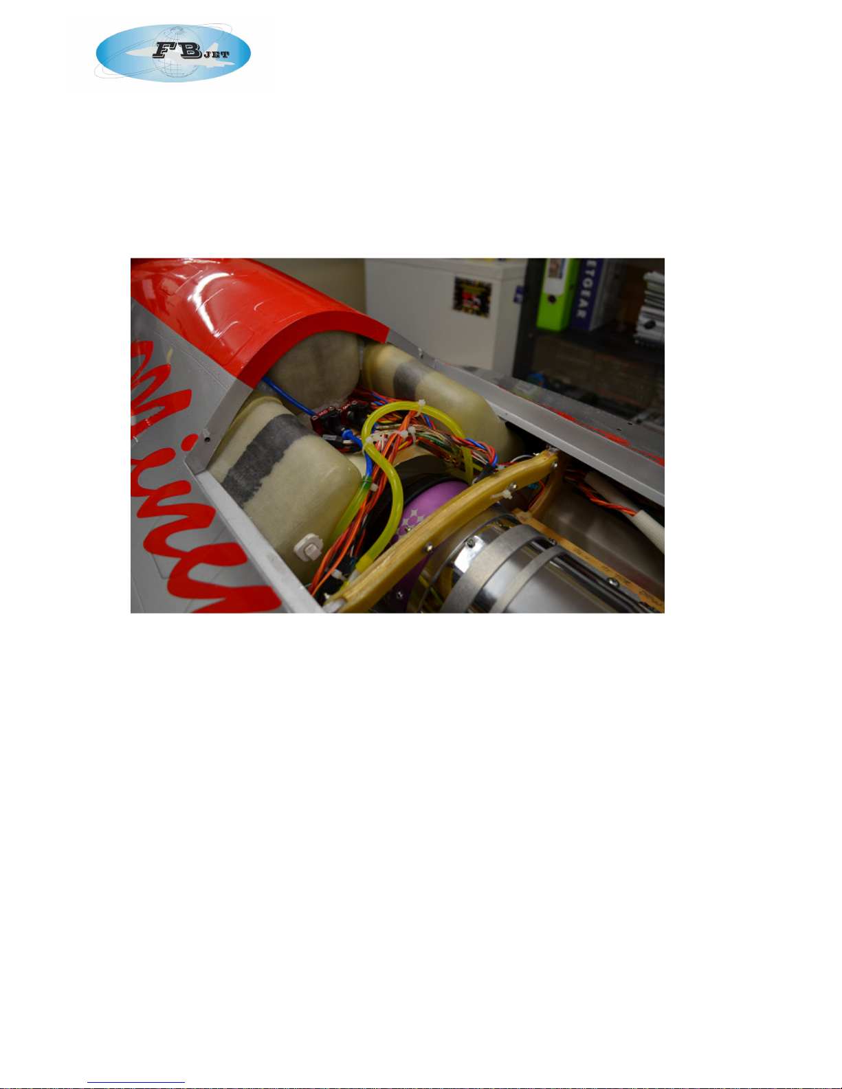
photo 1 – Tank Layout
• Re-attach the Tygon tubing to the main saddle tanks. Make sure the lines are of equal
length. Exercise care not to break the tanks while fitting the Tygon. Slowly wiggle the tubing
into place. Wire tie for security.
• Insert the saddle tanks into position. They should be a fairly tight fit. Here I have used a clear
silicon or you can use goo to secure in place.
• As photo 1 shows, the tanks fit in nice and tight.
You will need to make a centre tank support from scrap ply to for the front of the tank to make the
tank level this should be fitted once only once the air intake has been installed. This tank needs to
slide to the rear of the fuse with the rear of the tank at the front of the engine hatch. As detaukled
in Photo 1
• It also needs to incline slightly from rear to front to insure adequate clearance for the
engine hatch.
• Temporarily position the lower engine bypass on the mounting rails. I have had to modify
the bypass to account for the rotation of the main wheels. You can modify the bypass as I
have to maintain a by-pass flow in conjunction with the main undercarriage housing.
• This will also assist in the stabilisation of the trust tube and help to centre this with the thrust
line of the engine.
• Do not slip and secure the intake extension into place until you have finalised the nose
wheel installation. THIS STEP IS MOST IMPORTANT
• Connect all three fuel tanks together. As I prefer to run my fuel tanks in series when using
multiple tanks, the sequence of filling of tanks is as follows:
Page 7
FEI BAO F-16 1/6TH
1. Intairco UAT
2. Left Saddle Tank;
3. Right Saddle Tank;
4. Centre Tank.
• Check the position of the tanks once more with the engine hatch in place. When satisfied,
tack glue the tanks in pace with silicon, hot glue of goo.
• If you prefer to establish the tanks in parallel first:
• Check the fuel lines for nicks and cuts as you proceed through the next steps.
• Connect the two fuel pickup lines from the saddle tanks together with a “T” fitting.
• Connect this “T” fitting to the vent line of the center tank.
• Connect the two vent lines together from the saddle tanks with a “T” fitting.
• Attach this “T” fitting to a fuselage vent fitting. It is suggested you place this just ahead of
the right fuselarge leading edge. This will prevent “catching” the fitting if you slide the
fuselage on a foam transport pad. Reinforce the fuselage with a scrap piece of carbon
fibre to add a little strength to this area.
• Connect the fuel pickup from the center tank to the optional UAT or to the fuel pump. I
have located the UAT at the rear of the equipment board which has worked well with
balance.
Step 4: Nose gear
To ensure a smooth operation nose steering and retraction function on the F16 nose wheel, it is
ideal to pull the front nose retract from the airframe to work on it. In doing this your can check the
retraction and rotation function of the nose wheel assembly with ease.
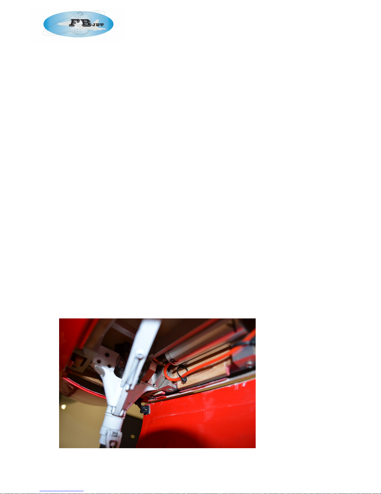
• Install your nose wheel steering servo. Remember not to use the rubber grommets.
Connection the arm of the servo to the steering arm of the nose wheel and centre with the
nose wheel extended.
• Connect your servo to your RX, centre the servo and while it is powered up, check the
retraction of you nose wheel with a hand pump.
• When you are satisfied with the function of the nose retract and the servo arm etc, re-install
the front retract into the airframe and check function again with a hand pump.
• Do not use rubber grommets and make sure to use Loctite on the screws.
• If your servo has a reinforcing ridge on the mounting tab, you may need to remove it with a
razor knife to allow the servo to sit flat.
Photo 2 – installing nose gear steering servo
Page 8
FEI BAO F-16 1/6TH
• When satisfied, use a small drop of thin CA on each clevis to lock it on to the threaded rod.
Step 5: Nose Doors
It will be helpful at this point to ensure that you are happy with the function of the nose door. The
manufacturing process on this model is very high and we did not have to change this at all.
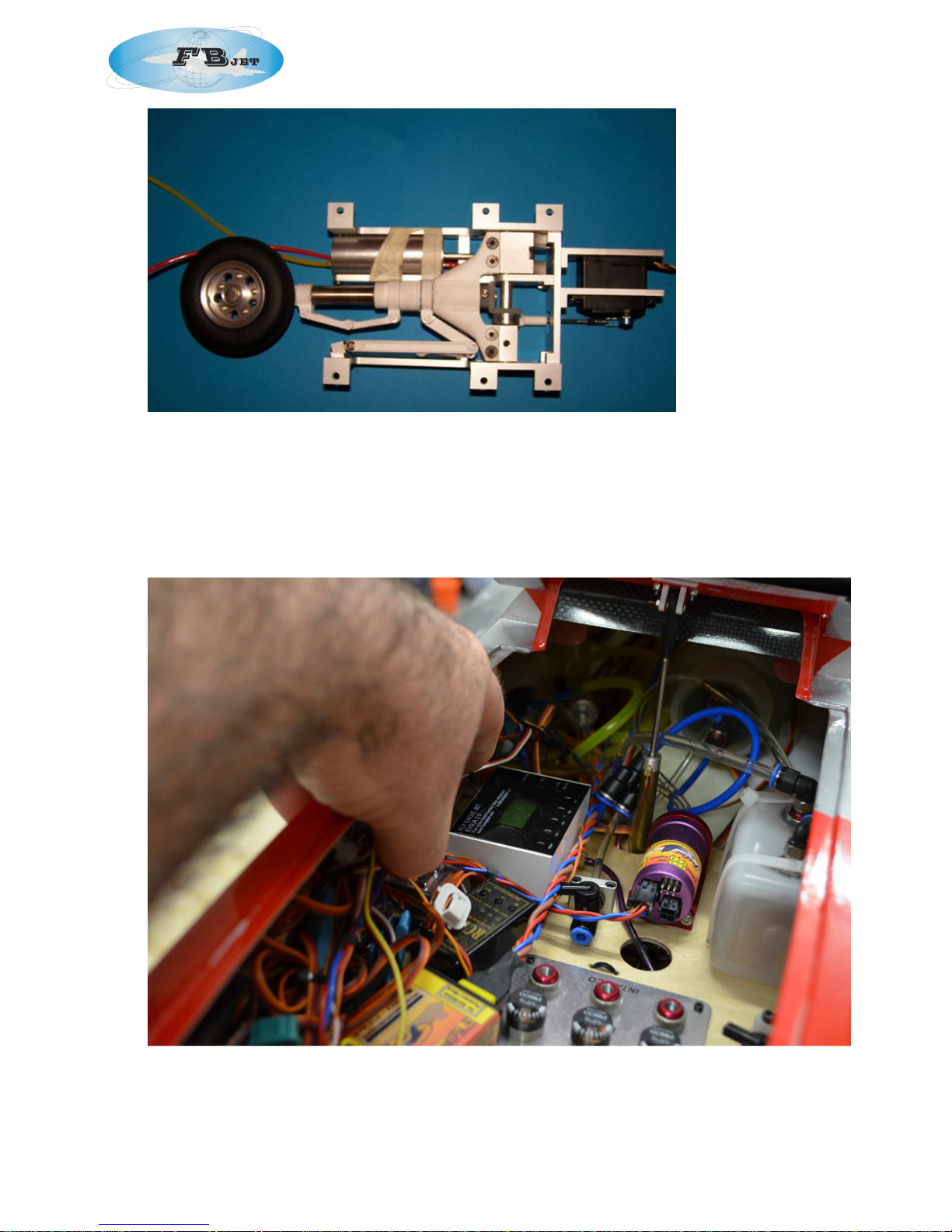
Photo 3 – sample layout of air systems on forward component board. Leave room for cockpit
above
Page 9

FEI BAO F-16 1/6TH
• Refer to the general construction tips for an explanation on gearing up the air systems.
• Install two air tanks in the space behind the rear component board, with the large tank in
the middle. Use several dots of silicone glue such as Zap-a-Gap-a-Goo. Don’t overdo the
glue, however, as you may want to remove the tanks in the future.
• When the glue is dry, run air system lines to the tanks. In our F16, all air and fuel fill lines are
run to the rear component board for air and fuel filling and gauges as this assisted in
balance and the prevention of the use of lead.
• Layout the air system components on the rear component board and then bolt the board
into place with four small wood screws.
• Run air lines to the nose gear and nose door cylinders. A little patience and good skills with
a forceps will be required. Test each line as you go with a hand pump for leaks. It will also
help to follow a colour coding scheme for future line identification and trouble shooting.
• Be sure to locate the main undercarriage air tubing clear of the engine and with the
modification of the bypass protection of the air tubes to the main undercarriage can be
achieved.
Step 6: Vertical Fin and Rudder
• Before attaching the aft section of the fuse, the vertical fin and horizontal stabilizers need to
be attached and the wires run from the servos. This is because the pipe must be in the aft
section when installed, and access to the wiring is restricted once the pipe is in place.
• In most kits, the hinges are preinstalled in the control surfaces, but must be glued into the
flight surface. This is true for the rudder and fin. As the elevators are full flying, appropriate
installation with the servo connections is required.
• When removing the servo well covers, label appropriately for proper re-installation.
• Trial fit the rudder into the vertical stab. You may need to snip about 1/8 inch off the bottom
hinge as it butts up against the rear aluminium spar. Trim and sand to achieve the maximum
throw your servo arm will allow.
• Attach two aluminium “L” brackets to an 8411 servo or equivalent. Position the brackets
such that the spindle of the servo faces forward when installed in the servo well. Do not use
the rubber grommets supplied with the servo, but bolt it directly to the brackets. Use Loctite
as required.
• Using a JR Matchmaker or your receiver, power up the rudder servo and set it at neutral.
Attach the control arm at a vertical position.
• Position the servo on the two ply mounting tabs and attach the “L” bracket with 15mm
wood screws.
• Run the servo wire out of the bottom of the vertical stab.
• Trial fit the phenolic control arm in the slot routed in the rudder at the factory. You may
need to use a small carbide cutter to enlarge the slot slightly for a good fit. Be careful not to
route through the other side of the control surface. A small piece of tape wrapped around
the cutter at the proper depth will help prevent a mishap.
• Roughen the surface of the control arm where it will glue into the rudder with 100 grit
sandpaper.
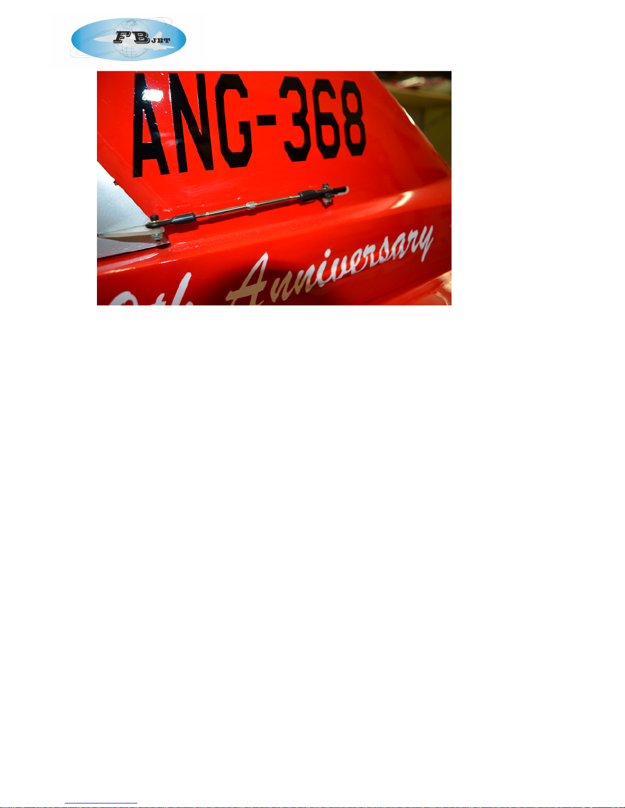
• Tape around the slot with masking tape and apply a liberal amount of Aeropoxy or Hysol
into the slot (photo 4) to ensure it is secure but with no glue on your surfaces.
Photo 4 – Installation of control horns
Page 10
FEI BAO F-16 1/6TH
• Secure the hinges into the vertical stab and the control horn into the rudder with
Aeropoxy/hysol. Remove the masking tape and allow to dry overnight. Make sure to check
the vertical stab for any glue marks or fingerprints before setting it aside.
• Locate two 15mm bolts and large washers. Trial fit these in the vertical stab mounting posts.
• Insert the vertical stab into the aft section of the fuselage and secure with the two bolts.
• Install a servo extension of the proper length to reach your receiver and secure the
connection with a large piece of heat shrink or tape.
Step 7: Horizontal Stabilizers
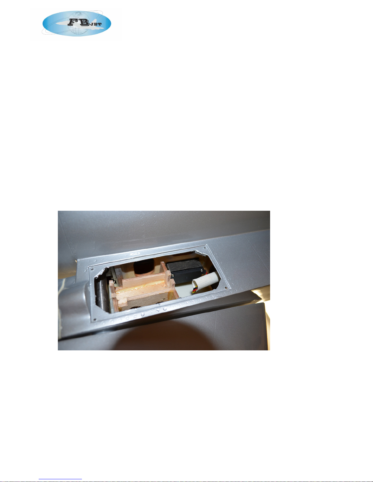
• The horizontal stabs build up in a similar fashion to the vertical stab in terms of the servo
installation. Remove the servo covers on each side of the fuse. Install your servos in the
space provided and modify slightly as required if your selected servo does not fit. Repeat
all steps, including the installation of the servos.
• Before installing the servos, use a Matchmaker or equivalent to centre the servos and
match the positions of the control arms.
• If you are using JR Heavy Duty Arms and the positions don’t match, try rotating one arm 180
degrees before deciding which half of the arm to trim off.
• If you are installing 8611 servos, you will need to trim the ply mounting tabs and metal arms
to get a good fit.
• Some may say not to balance your elevators because it may cause flutter but I tend to
differ, If your servo gear mesh and linkage is tight with out any play there should not be a
problem whether it is balanced or not and if there is play in the gear mesh or linkage then
you will probably get flutter either way. By balancing the elevators you reduce the extra
strain on the servos gear train and with the precise digital servos we have today, balancing
will stop the bussing sound you will get from the weight of the elevators pushing down from
the gravity.
• To balance the elevators drill a hole approx. ½” in diameter with either a dremel or a drill on
the inside flat edge of the elevator, approx. 3½” from the corner of the leading edge. If you
decide to use a drill, a tip to prevent breaking the elevators seam is to start out with a
smaller bit and then go bigger till it is approx. ½”. I used about 35 grams of BB’s for weight
but anything like small pieces of lead, pellets, buckshot or birdshot will work in the hole to
get the elevator to balance.
Page 11
FEI BAO F-16 1/6TH
• I simply added weight and fitted it back into the elevator slot in the fuse to check balance.
• Once satisfied, use silicon and place a liberal amount in the hole and place the lead into
the silicon
• Keep adding weight till it starts to stay down or not move in a horizontal position. Repeat
previous step for the other elevator.
• Install the elevator servos into the fuse and connect to the control arm attached to the
elevator mechanism.
• This is an important step to ensure that the installation is tight and all screws and fasteners
are tight and installed with locktite.
• do not use the rubber grommets as they may cause flutter if there is to much play.
• Attach a 36" heavy-duty 22-gauge extension to each servo. Tape the connections for
safety.
• Copy these steps for the other elevator and then centre nd match both elevators to the RX
system.
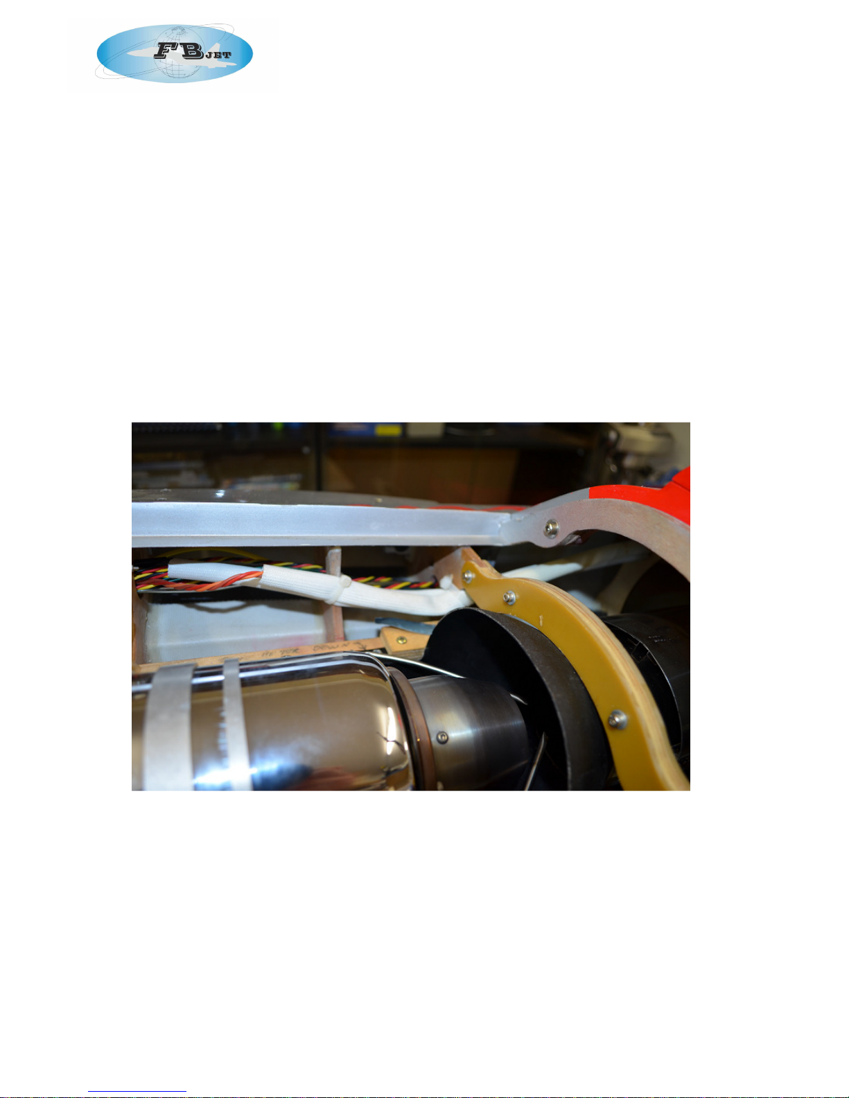
• Run the elevator servo extensions from the rear of the fuse forward. I tend to run these
extensions and the rudder extension lead through a Teflon tube for heat protection from
the thrust tube.
Photo 5 – elevator servo installation
•
With control arms in the vertical position and the control surface centred, adjust the
linkages to the proper length for both elevators and the rudder.
•
With the two elevator servos activated through the Matchmaker, set the length of control
linkage such that the elevators are equally centered and attach (photo 20). Make sure not
to over tighten the bolts such that the arm binds.
•
Replace servo covers.
Page 12
FEI BAO F-16 1/6TH
Step 9: Aft Fuselage
• Drill a hole in the pipe mounting tabs at their mid-point.
• Position the pipe on the rear of the lower bypass. The tabs are slightly offset to one side of
the pipe this is the top.
• With the pipe fully on the lower bypass, and the mounting tabs equally spaced from the
top, drill holes through the engine block mount and attach/secure the pipe tabs to the
block.
• We found that we needed to cut the bottom out of the lower bypass so that it butts up
against the main wheel well enclosure. This will ensure that the bypass function is still
achieved and will also make the bypass installation achievable so that it can support the
thrust tube.
• Insert the pipe into the aft fuse.
• Attach the aft fuse to the forward fuse with four bolts. BE SURE TO Loctite these bolts.
• Secure the wire harness to the side of the fuse to keep it away from the pipe (photo 6).
Photo 6 – mounting aft fuselage
Step 10: Engine and Pipe
• Clean the fuselage thoroughly before installing the engine. If you need to trim the intake for
engine clearance, use a vacuum while you work. This will reduce the chance of a foreign
object finding its way into your engine later;
• Before installing the engine, slide the air intake into the front fuse. This air intake needs to
slide far enough forward and over the leading edge of the air intake enough to ensure
clearance of the steering servo arm. Mark a line where the air intake needs to be then
remove and place either silicon, goo or hot glue into this area before reinstaklking the air
intake.
Page 13
FEI BAO F-16 1/6TH
• Reinstall air intake into the fuse and push as far forward as possible to the pencil mark you
made.
• Secure the lower bypass on the outside of the air intake and secure with silicon or the like.
• At this point, you can also secure both saddle tanks in place with silicon as well. These
should be a very tight fit so add silicon to ensure they do not move. Place tanks as seen in
these pictures.
• Move the pipe aft and position the lower bypass on the mounting rails. Trim the engine rails
as necessary for a good fit.
• Bolt the pipe mounting tabs to the engine mount as detailed.
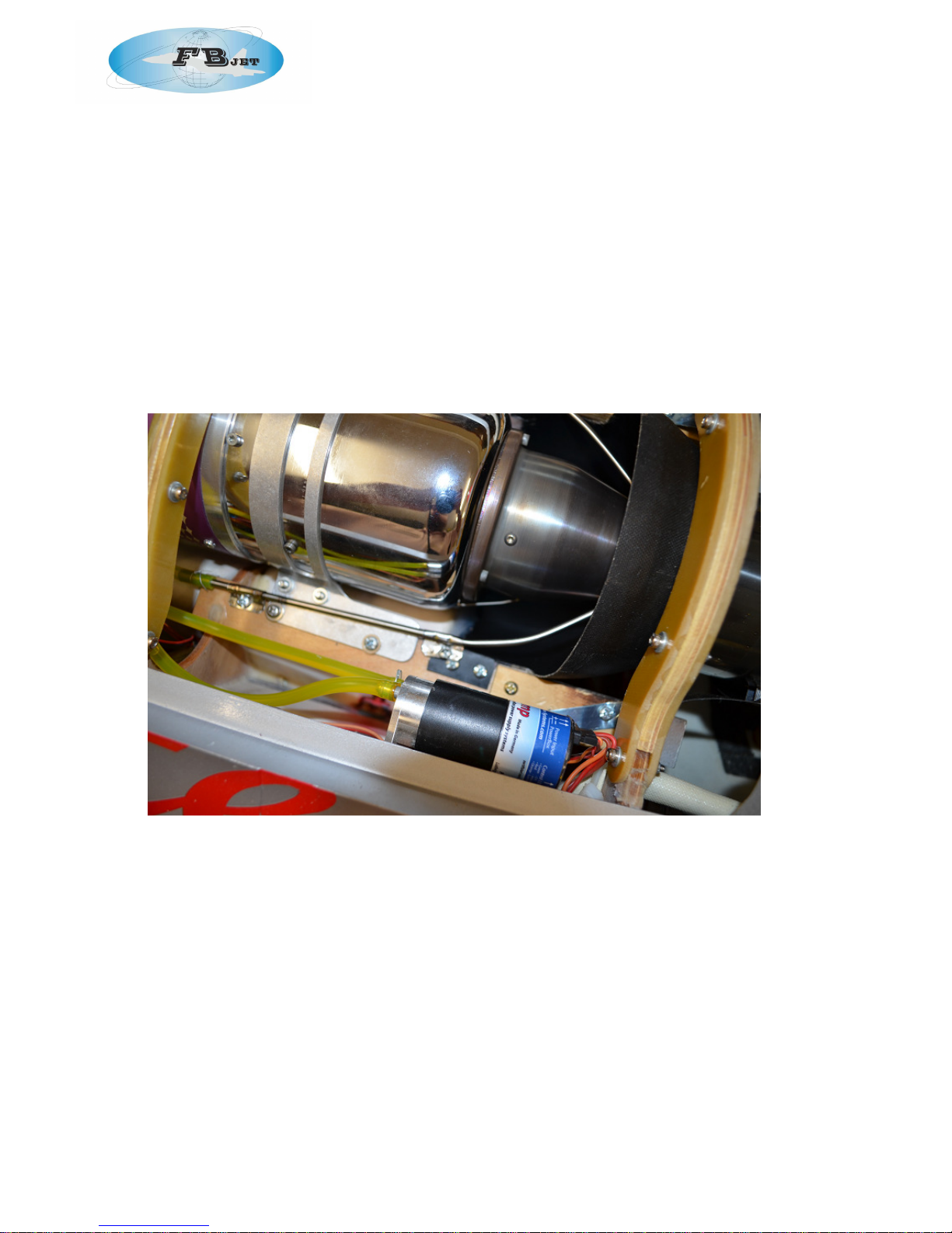
• Position the aft end of the exhaust pipe either even or just inside the fuse at the rear exhaust
opening. (Photo 6).
• Trim the intake such that it extends inside the lower bypass by approximately ¼ inch.
• Slide the pipe/bypass assembly to the rear again, and slip your engine into the lower
bypass. Move the entire assembly forward into position.
Photo 6 – position of aft pipe
• Adjust the location of your engine to obtain the clearance specified by the manufacturer
between the exhaust cone and the pipe mouth. It is likely it will extend into the intake.
• Shim the engine as necessary to make sure it is centred in the pipe and is aligned with the
slope of the pipe from front to rear.
• When you are satisfied, bolt the engine to the side frames with wood screws. Remove the
screws and coat the thread holes with thin CA. This will harden the wood.
• Connect service lines to the turbine and bolt permanently in place (photo 7).
Page 14
FEI BAO F-16 1/6TH
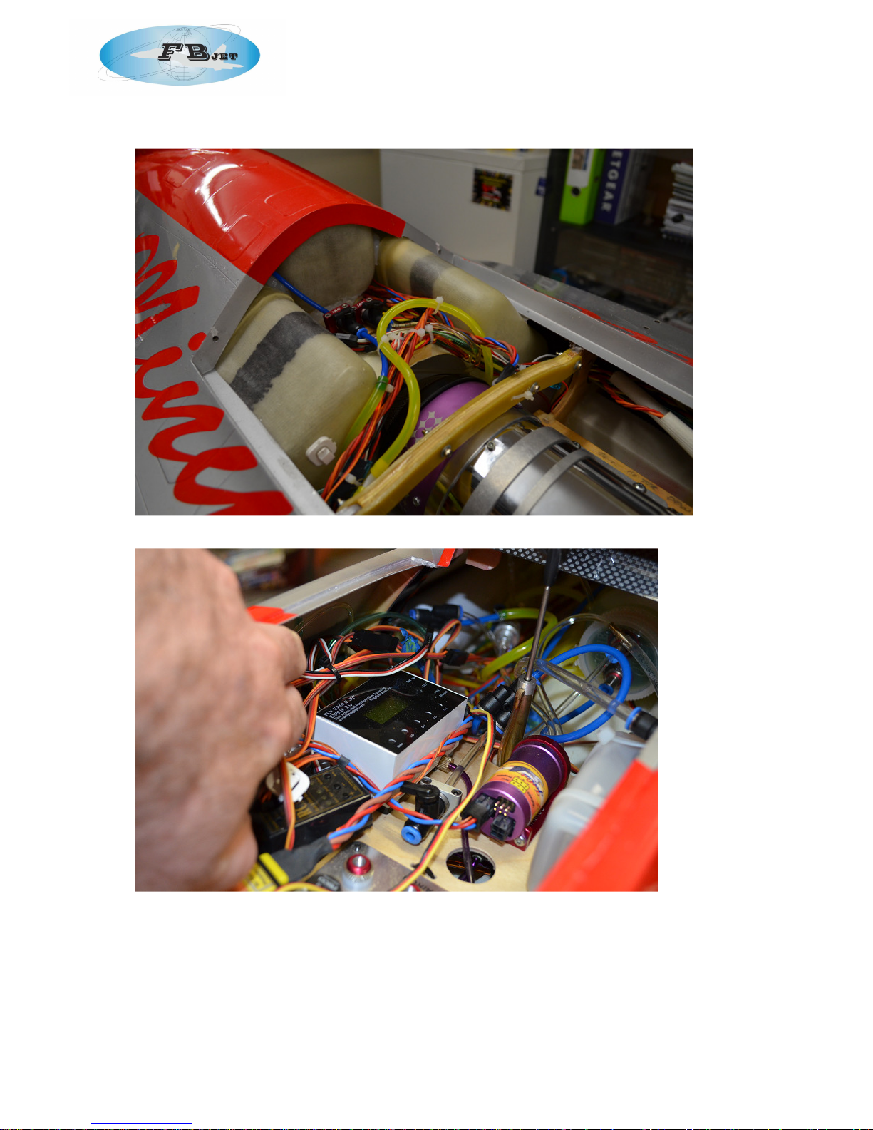
Photos 7 – Service lines to the engine
Photos 8 – rear component board. Note receiver position on upper right.
• Drill and secure the bypass to the engine mounting rails with four wood screws if necessary.
• If the pipe is loose as it passes through the rear former, glue a piece of ply at the top of the
former to hold the pipe more firmly in place. Access is from the rear.
• Complete the installation of engine components on the rear component board.
• Remember to leave clearance for the cockpit above. The placement of components in my
F16, including the smoke system, is shown in photos 6. The smoke tank was located next to
Page 15
FEI BAO F-16 1/6TH
the main tanks and centre tank to reduce as much as possible the change in balance
when the smoke is used.
• Resist the temptation to hide wires away under the component boards, as it will make
future maintenance more difficult. Keep things neat but accessible.
• Also note that the F16, when the cockpit is installed has a very shallow fuse. We found that
where possible we minimised the use of tall RX and equipment in the forward component
boards. For example the additional charge and IO board for the jetcat RX series was too
tall to install together with the cockpit. Therefore, you will need to locate else where of
choose a difference item.
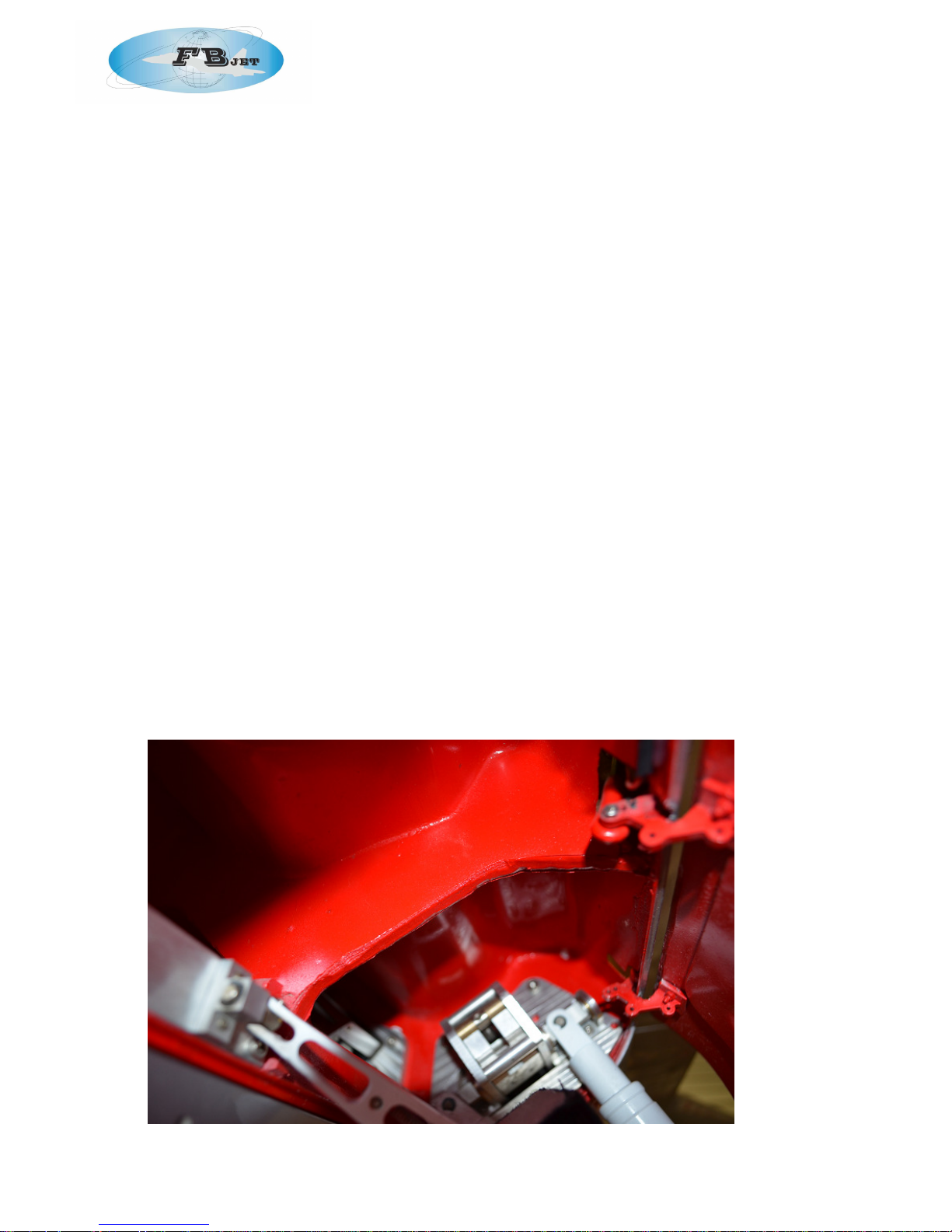
Step 10: Landing Gear and Doors
• Extend main gear and unscrew and move to once side/
• Put a drop of thin CA into each screw hole to strengthen the ply in the area of the bolts.
• If not already done, attach air lines to the main gear and check for leaks with a hand
pump.
• Attach brake line and check for operation of the brakes and leaks with a hand pump.
• Optional step: The gear door cylinder may be attached to a small extended “ear” on the
door hinge. To reduce the risk that this ear fails, you may wish to move the ball link attach
point to the hole immediately next to the “ear”, but drilled through the main arm itself. If
you undertake this optional step, you will also need to move the bolt location on the
cylinder base mounting plate so as to maintain appropriate throws. The factory installation
is very good so we did not need to undertake this step.
• Attach air lines to the door cylinder from inside the fuse if not already accomplished. Test for
leaks.
• Put a drop of thin CA on the small nuts at both door cylinder bolt locations to reduce the
risk that they loosen over time.
• Route all air lines to the nose and ensure they cannot be damaged by other components.
• Reinstall main gear. Check for smooth operation with a hand pump.
• Wire tie the brake line to the main strut and check operation of the gear once more to
make sure brake line has adequate length and clearance.
• See photo 9 for picture of completed main gear and door cylinder installation.
Photo 9: Main gear
Page 16
FEI BAO F-16 1/6TH
Step 11: Aileron Servos
• Remove the aileron servo covers. Mark the inside front of the covers so you will know how to
orient them for reassembly.
• Attach the aluminium L brackets to the servos as you did for the tail surfaces. The servos will
face in opposite directions and the servo spindle is positioned toward the front of the wing.
• Using your receiver or JR Matchmaker, power box or the like, find servo neutral and attach
the heavy-duty servo arms to obtain matching positions. If you are using a double-sided
arm, you may find that rotating the arm 180 degrees achieves a better match, so complete
this step before trimming off the unused side of the arm.
• Temporarily fit the ailerons to the wing if not already completed at the factory. Note the
wire that runs through the hinging is or a screw type at the wing root. A small flat screw
drive and do this then fingers.
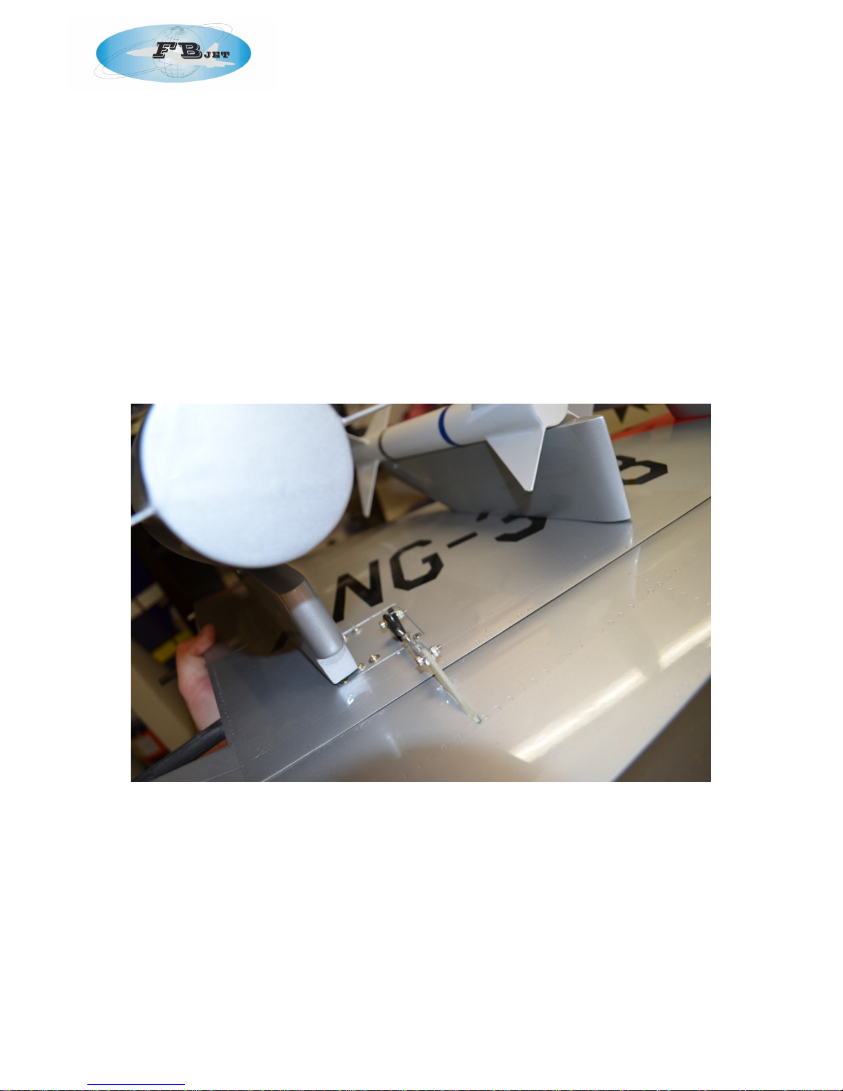
• Position the servos onto the mounting tabs, paying attention to the position of arm relative
to the control horn slot marked on the control surface. Using great care not to pierce
through the top of the wing, drill and bolt the servos in place (photo 10).
Photo 10 – Aileron installation
• You will need to use an extension on the aileron servo lead.
• Make sure to tape or heat shrink the connection.
• Trim the servo covers for the servo arms and reinstall.
• Repeat for the other wing.
Step 12: Ailerons
• Measure the throws for ailerons. Make sure you can achieve 30 mm in either direction on
the ailerons. Carefully trim away the gap cover if needed to get the appropriate travel.
Also make sure there is no binding at the ailerons.
• With a small carbide cutter, route out the slots for the control horns.
• Rough up the mounting surface of the control horn, tape around the slot and glue the horn
into each control surface with Aeropoxy or Hysol.
Page 17
FEI BAO F-16 1/6TH
• Set the wings aside for the glue to cure. Double check to make sure there are no
fingerprints or excess glue on the wing surfaces. (cigarette lighter fluid will help remove
fingerprints)
• When the glue has cured, install the linkages.
• Insert the wing tip missile rails into the mounting holes. When the pins are fully inserted,
tighten the locking clamp bolts through the small holes in the top of the fuse.
Step 14: Cockpit
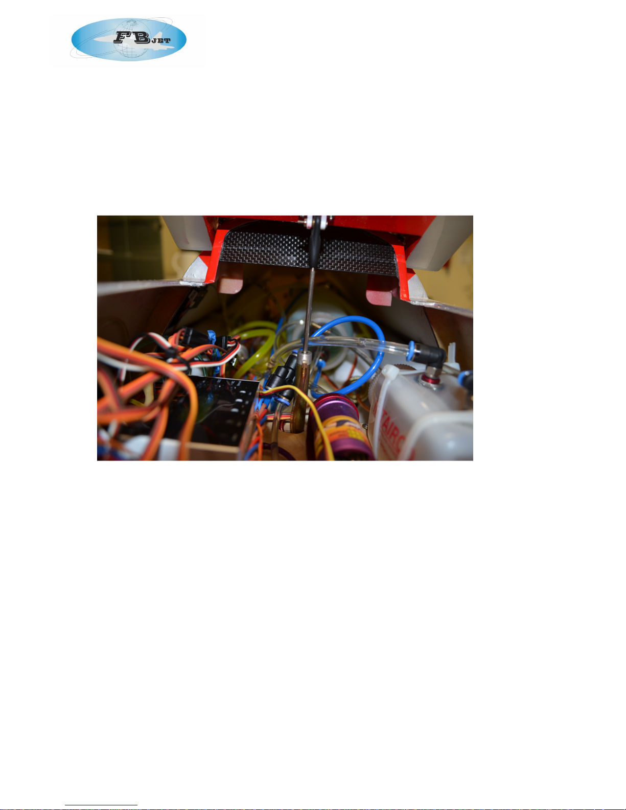
• Trim the edges of the cockpit area so that the tub sits down fully into the forward fuselage
(photo 11).
Photo 11 – trim the sides of the cockpit area such that the tubs drop in place
• Make sure both tubs clear any electronic gear sitting on the component boards.
• At this point, you may wish to paint the tub, instrument panel and glare shield with flat black
paint.
• Trial fit the tub into the fuse to ensure a nice fit. Locate the air ram for the canopy and
check attachment fit.
• We included a sequencer for the canopy function and added a air ram to the fron of the
canopy area so that when the canopy is in the closed position, the second air ram acts as
a lock pin.
Step 15: Radio Programming
• Complete the installation of your radio gear and batteries. In our F16, the switches were
mounted on the front component board together with the RX, ECU shut down, ecu etc.
• The rear board has the air equipment and the UAT together with the fuel fill valves;
• Batteries were mounted to the nose forward of the front component board so they can be
removed for charging if required. We used 2* 4000mAh 7.4v Lipos and a 9.9v Life for the
Jetcat 180RX.
• Set your radio for the following throws:
• Ailerons: 20 mm in either direction
• Elevators: 30 mm in either direction
• Rudder: max throw allowable
Page 18

FEI BAO F-16 1/6TH
Step 16: Weight and Balance
• Test fuel the aircraft. Check for leaks, then drain.
• Set your CG. For the initial flights, the plane should balance slightly nose down with the CG
on the wing spar, fuel in the UAT only, with the gear down.
• Adjust CG as necessary.
• CG is correct at 180mm from the leading edge of the wing @ the wing root.
Step 17: Test Flight
• Before any test flight, make sure all systems are fully tested on the ground and there are no
known problems. The gear is essentially important to ensure that it is functioning correctly.
• Try to conduct test flights under ideal weather conditions, at a flying facility that offers
plenty of “outs” in case of problems. The F16 enjoys a head wind on take off and landing.
We deactivated the speed brakes for a first flight and actually found that this model by FB
jets slows up superbly without speed brakes.
• During the first flight, spend the majority of time on slow flight and approaches. Your primary
goal in the first few flights is to get a good feel for throws, CG and most importantly, the
landing characteristics of the aircraft.
• This is a heavy aircraft, so make sure to carry sufficient power to touchdown to avoid wear
and tear on the airframe. Land with a little speed.
• Ailerons = 30mm 30% expo
• Elevator = 60mm up 30% expo – 50mm down 30% expo
• http://www.tmac.asn.au/Event%20Day%20-%2025th%20November%202012%20Bi-
Plane%20&%20Warbirds%20Day.htm
Equipment Installation Photos
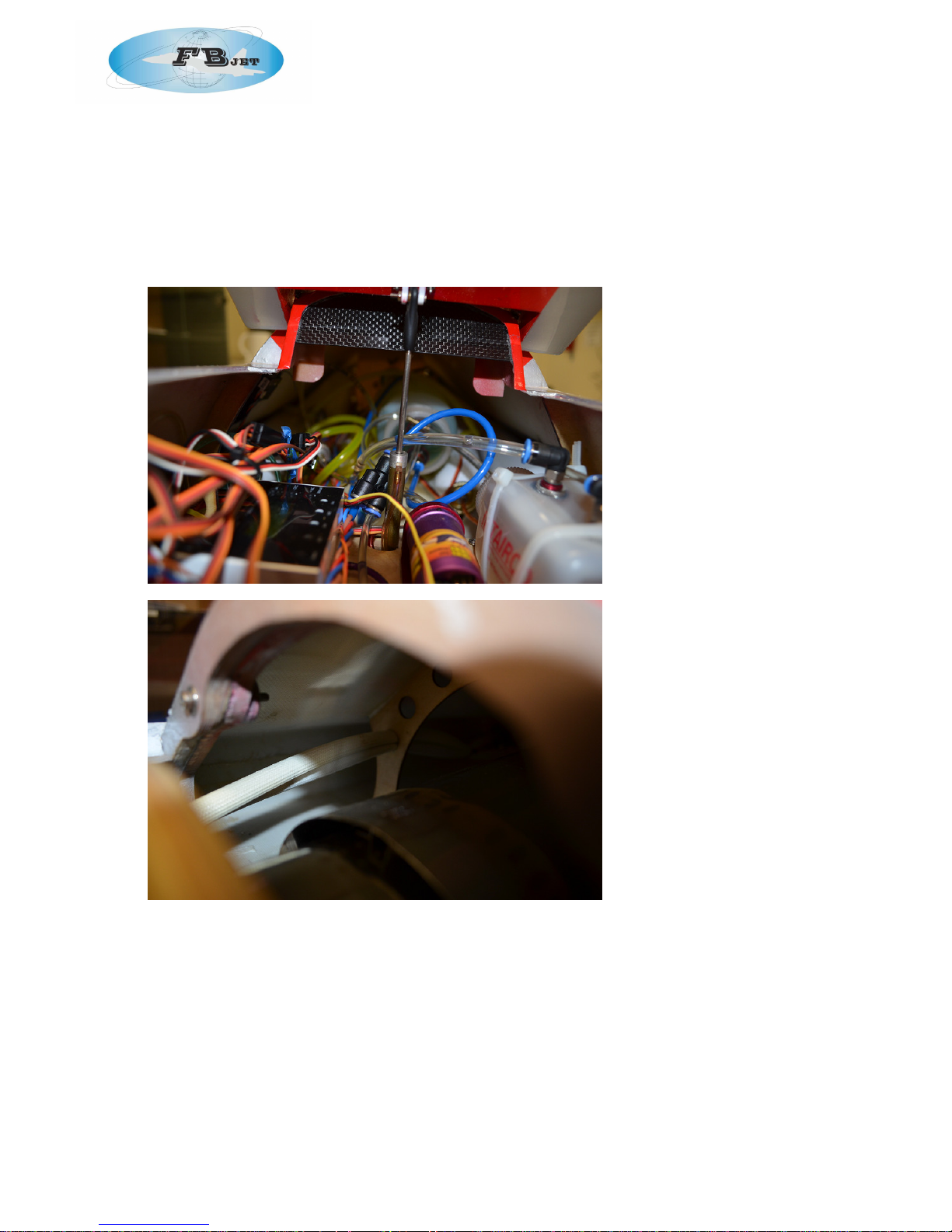
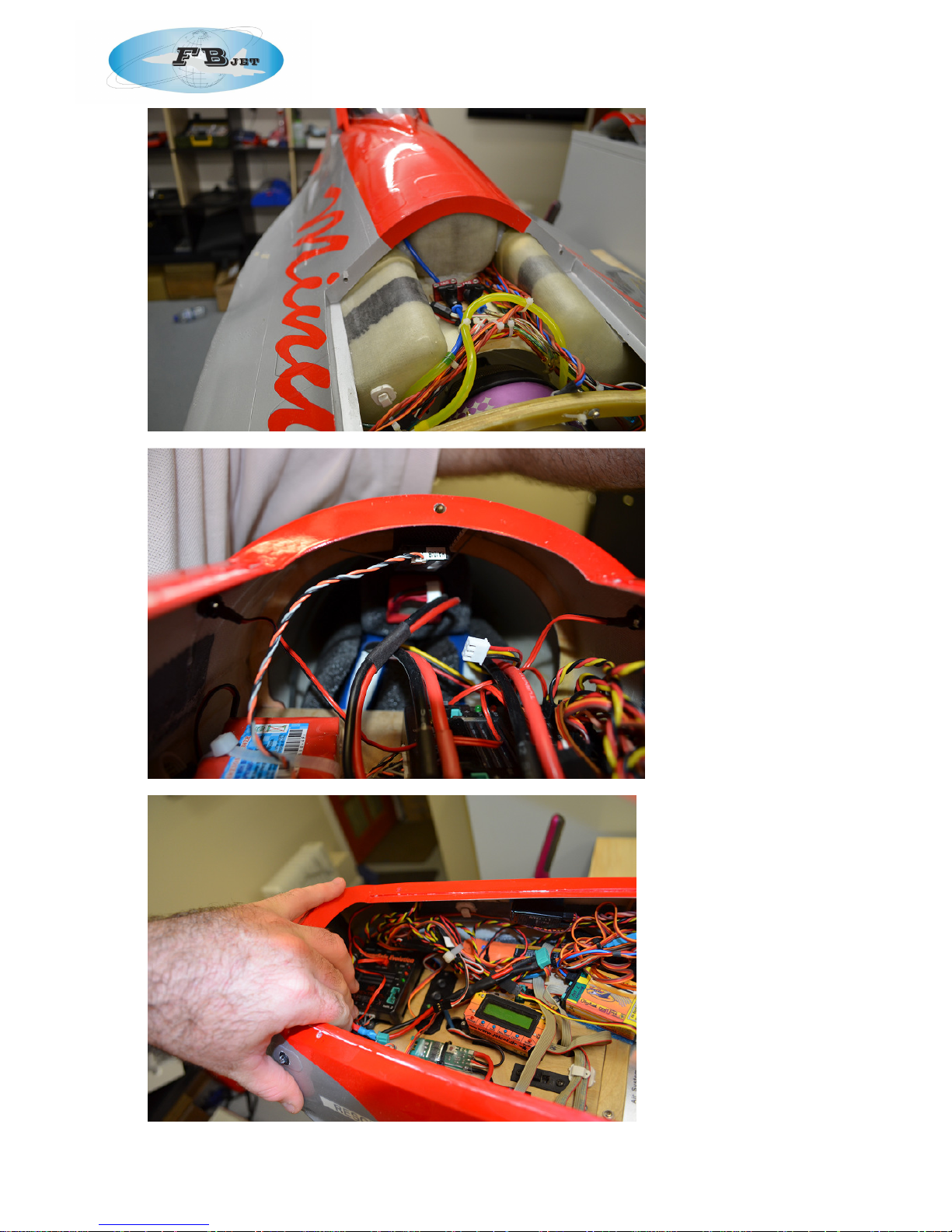
• Equipment, including fuelling tubes, switches, air fill, air gauges and remote ECU board were
all installed in on the component boards to have as much weight forward as possible. Also,
the wiring for the ECU and for the servos were run down opposite sides of the fuselage to
avoid interference. The receiver was mounted on the front component board. This is a
good location for both conventional receivers and 2.4 GHZ units, due to the central
location, high mounting point and absence of carbon fiber in the area. If you are using
multiple 2.4 receivers, this general location allows for additional units both fore and aft. The
positioning also allows for the shortest run of extension wires.
Receiver and ECU batteries were located on in the nose within fitted foam and prevented from
sliding backwards by the forward component board.
Photos 17 show some of the installation details air systems and remote ECU board
Parts List
• Forward Fuselage and Component Boards
• Aft Fuselage
• Engine Hatch
• Canopy
• Horizontal Stabs, Elevators (2)
• Vertical Fin, Rudder
• Wings, Ailerons (2)
• Wing Tip rails for missles (2)
• Main Landing Gear (2)
• Nose Gear with Integrated Steering Bracket
• Kevlar Saddle Tanks (2)
• Main Center Tank
Page 19
FEI BAO F-16 1/6TH
• Fiberglass Intake Extension
• Cockpit Tubs, Rear Instrument Panel
• Dual Wall Exhaust Pipe with Mounting Tabs
• Upper and Lower Bypass
• Large Fuse fences (2)
• Linkage Assemblies (7)
• Air Support Kit
• Hardware Kit
Page 20
FEI BAO F-16 1/6TH
Page 21
FEI BAO F-16 1/6TH
 Loading...