

Page 1
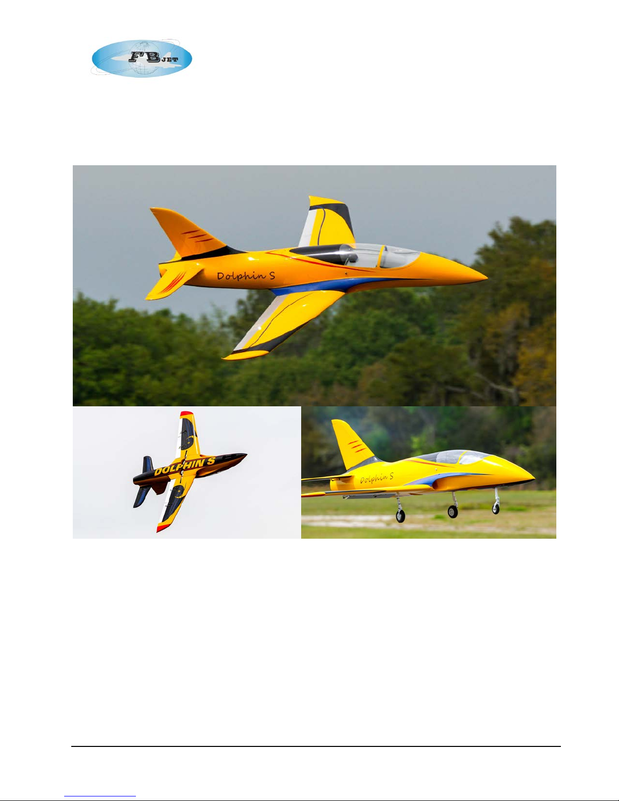
FB Jets Dolphin S
FB Jets / Feibao
Dolphin S Assembly Manual
Written By Rich Miller in Collaboration with Fei Bao Jets
Cove r Photos by Robert J . Eng l e
Rev. 0
1
Page 2

FB Jets Dolphin S
Contents
DISCLAIMER: 4
Introduction 5
Specifications 7
Component Size (Length) 7
Adhesives 8
Standard Pneumatic LG Systems 8
Optional Electric LG Systems 8
Parts List: 8
Optional Equipment 9
Additional Equipment 9
Optional Equipment (Builders choice) 9
Servo List (Hi-Tec) based on 6V torque specifications 10
Servo List (JR) based on 6V torque specifications 10
Construction 10
Pneumatic Landing gear 11
General 11
Step 1: Nose Gear 11
Step 2: Main Landing Gear 12
Step 3: Forward Fuselage 13
Optional Battery Box 14
Step 4: Fuel Tanks 14
Tank Assembly 16
Tank Mounting 17
Saddle Tanks: 17
Optional Mounting: 17
Step 5: Final Fuel System plumbing: 20
Step 6: Air Tank Installation 21
Step 7: Aft Fuselage 21
Step 8: Wing – Servo Installation 22
Step 9: Vertical Fin and Rudder servo installation 24
Step 10: Horizontal Stabilizer and Elevator servo installation 25
Front equipment t ray 27
Step 12: Turbine Mounting Rails and Tail Pipe 28
Step 13: Turbine Accessory Installation 28
Step 14: Cockpit 29
2
Page 3

FB Jets Dolphin S
Step 15: Radio Channel Assignments 30
Step 16: C.G. 30
Step 17: Setting of throws 31
Maintenance Tips: 31
Annex A Drawings 32
3
Page 4

FB Jets Dolphin S
DISCLAIMER:
THIS IS NOT A TOY
This is a high-performance miniat ure aircraft, capable of high speeds and dam age to life, limb, and
property. The manufacturer and its distributors and auth or of this man ual cannot control how you
assemble t his model, what equipment you use to fi t it out, or how you fly it, and can assume no
liability whatsoever for any damages that may occur when you f ly your aircraft. B y assembling t his
model, y ou are agreeing to indemnify and hold blameless the ma nufacturer and/or his agents from
any and all torts and liability associated wit h the use of this product.
Please i nspect all parts before beginning asse mbly. If any part appears to be suspect, contact your
dealer or the manufactur er for repair or repl acement BEFORE you begin.
Once you have assembled the aircraft, you are the pilot in command and assum e any and all
responsibi lity for t he use of the model and any damages that might occur by fl ying or attempting to
fly this aircraft.
R/C model jets requir e a high level of skill in both their assembl y and their fl ying. If you do not feel
confident in either your building or flying skills, PLEASE seek assistance from more experi enced
modelers. It is a wise idea, no matter what level of skills you possess, to have a second
experi enced modeler go over your installati on after asse mbly. A second set of eyes may spot a
problem you have missed. If you have not flown a high performance model like this before, it is
HIGHLY recommended that you get an experienced turbine pilot to do your maiden flight. Very
often, the first few seconds of a mai den flight are cr itical until the aircraft is trim med out, and havi ng
an experi enced pil ot at the control s can make the difference between a wrecked aircraft and once
that enjoys many hundreds of flights. Be sure to select a suitable field for flying...take the time to
find a large paved runway if at all possible, especially for test flights, until you f eel comfortable
getting the aircraft in and out of smaller grass fields.
Note: In the USA it is mandatory that you belong to the Academy of Model Aeronautics and hold a valid Turbine Waiver, please check
the local governing rules for operation of R/C model jets of your location before flying.
Congratulati on s on your purchas e of t he FB Jet s Dolphi n S
4
Page 5
FB Jets Dolphin S
Introduction
You have chosen a model that represents the pinnacle of ARF technology and factory testing with
the new manufacturing processes implemented by FB Jets. While there is not a lot of building to
do, there is enough to keep y ou busy for quite a few evenings. Even if you ha ve assembled other
ARF jets, w e highly r ecomm end foll owing the assembly sequence and procedures presented in
this manual.
Please remem ber that just because the model i s almost completely built it does not mean that you
can rush through the fi nal install / assembly. It is this authors recommendation that any factory
installed systems suc h as hardware, linkages, fuel lines, retracts, wheels and brakes, be inspected
for any possible defects, loose parts etc., and al l fastener s should be secured with Loctite. Wheels
and brakes should be che cked for lubrication and for proper fit to the axel; threads on linkages
should be inspected for tightness.
The Dolphin S was designed to be modular to make for easy transportation, see “compone nt size”
in the specification section. The forward and aft fuselage se ctions bol t together with four bolts.
The thrust tube (pipe) remains in the aft section of the fuselage when the halves are separated.
When attaching the front and rear hal ves of the fuselage, the thrust tube can be slid towards the
back to allow clearance to gain access t o the four fuselage mounting bol ts. After joining the two
halves, the thrust tube can then be sl id forwar d to allow the mounting tab s of the bell mouth to be
screwed to the motor mou nt rails.
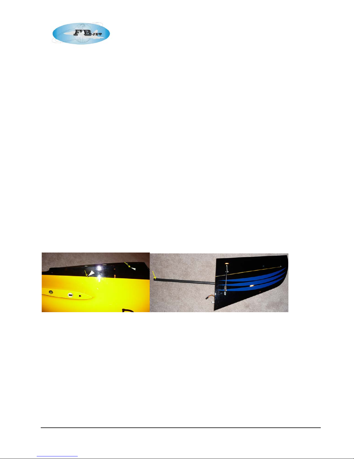
The Vertical fin is easi ly removed / installed utilizing the two internal clamping mechanisms that are
easily tightened with hex (Allen) wrenches through the access holes in rear fuselage as shown.
The right horizontal stabilizer has an integral carbon fiber spar, the left has a built in tube sock et.
Both have an ant i-rotation pin locat ed towards the leading edge. The right stabilizer is inserted into
the integral tube in the aft section of the fuselage.
through the fusel age allowing the left stabilizer to be slid onto the spar tube. The l eft stabiliz er is
then attached with one allen bolt into the CF spar, the spar bolt location is shown in photo, the
retaining bolt is i nserted from the b ottom of the left stabilizer.
Upon compl ete insertion, the spar w ill protr ude
5
Page 6
FB Jets Dolphin S
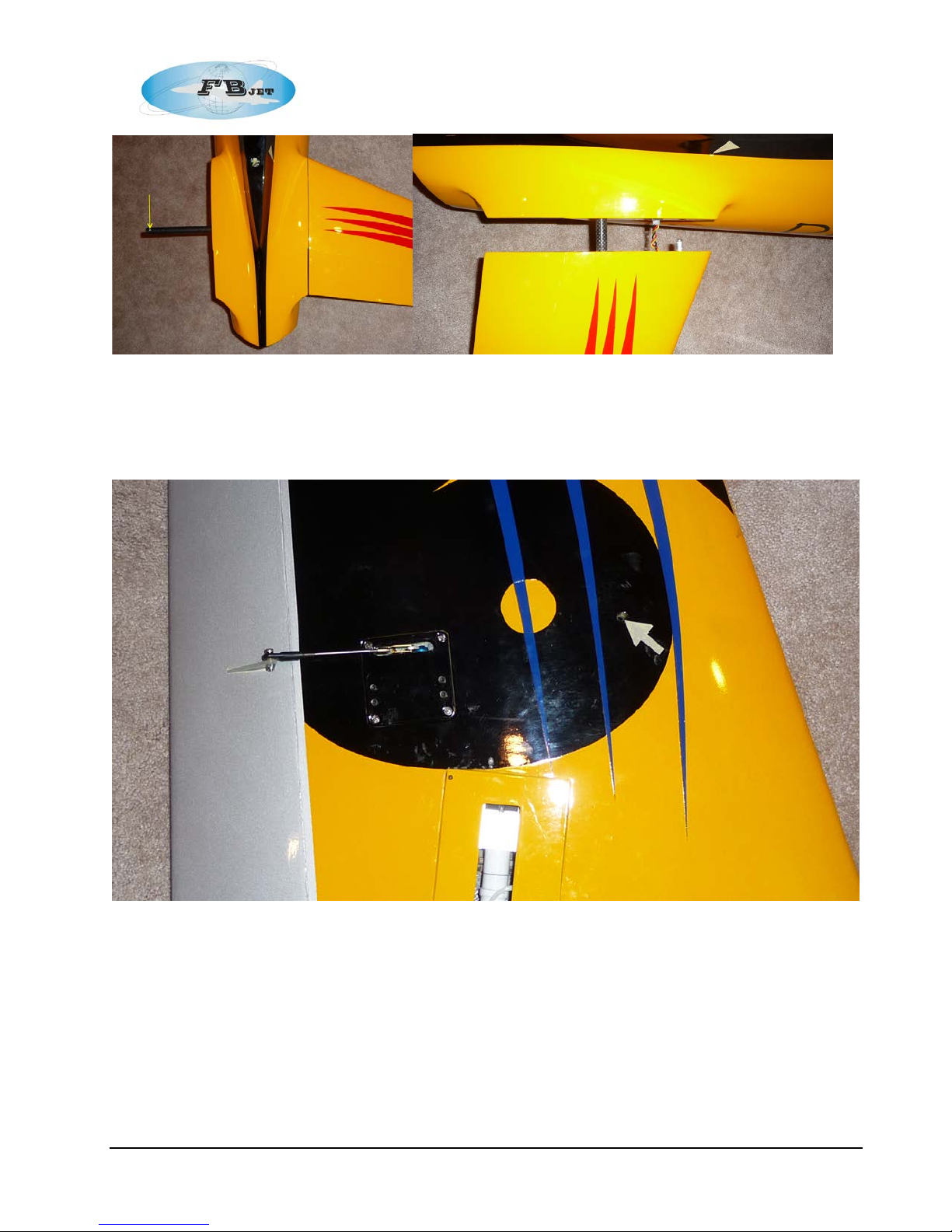
The wings utilize one carbon fiber main spar and have two anti-rotation pins, with one towards the
front and one towards the r ear of the root rib. The main spar has a 4 mm tapped hole in each
outer end, there is a hole location in of the wings that accepts a flat head 4 mm bolt to secure the
wing spar, locati on shown in photo.
When the model is completely t aken apart it will fit in a small area for transportation.
6
Page 7

FB Jets Dolphin S
Specifications
Total Length: 92 1/8” (2340 mm)
Total Wingspan: 81 5/8" (2073 mm)
C.G. Location 28% MAC: 10 1/2” (267 mm) from LE of Wing
Prototype Dry Weight with all components: 30 lbs (13.6 Kg)
Thrust Class: 22 to 36 l bs (100N to 160N) “Jet Central Cheetah use d in prototype”
Servos for Flight Sur faces & Steering (8)
Servos for pneumatic controls (2) or pneumatic valves
Fuel Capacity Right and Left Saddle Tanks: 34 oz ea (1000 ml ea)
Supplied Center Tank 68 oz (2000 ml)
Total Capacity 135 oz (4000 ml)
Component Size (Length)
Vertical Fin – 16 ¾” (425 mm)
Horiz ontal Stab (ea.) – 14 ½”” (368 mm)
Wing Panel (ea.) – 35” (890 mm)
Canopy – 39 1/2” (1003 mm)
Forward Fuselage – 62 1/8” (1578 mm)
Aft Fuselage – 30” (762 mm)
Total Pipe Length with Bell Mouth: 37 1/2” (952.5 mm)
Main Tir e Diameter 3 7/8” (98 mm)
Nose Tir e Diameter 2.9” (74 mm)
Prelim in ar y St e p s bef or e y o u be gin
Keep thi s in mind as you pro ceed
Look at EVERY assembly step you fi nish, and ask yourself:
“Could this cause a malfunction and crash my aircraft?”
A chain i s only as strong as its weakest li nk, and thi s is a high-performance aircraft that will be
intolerant of sloppy assembly t echniques. Even the smallest component is important and can
cause the loss of your airframe, so take the time to do things right, or redo them if they are wr ong.
Careful work will result in a long l asting aircraft that will give you years of pleasure, one loose
component could resulting the complete loss of the aircraft and all of t he component inside of it,
additionally someone c ould even get hurt. So please pause every once in a while when building
and double check your w orkmanship.
• Clean and i nspect all parts. Inventory them agai nst the parts list at the end of the manual and
notify the kit supplier of any missing component s as soon as possible.
• If the paint scheme you have selected is glossy, it is recommend ed that you apply a coat of
wax. Thi s will help resist dirt, stains and fingerpr ints during construction, and wi ll provide some
limited protection against errant glue.
• Vacuum out the remnants of packing materials that remain in the fuselage.
7
Page 8

FB Jets Dolphin S
Adhesives
The author prefers Loctite Hysol 9462 adhesive for all procedures. This is a very strong epoxy that is
thixotropic. “Thixotropic” means it does not run at all, but stays only where you put it. It is superior to
regular epoxy, even slow setting epoxy, because of this characteristic. Regular epoxy will run with
gravity as it dries, taking it away from where it is supposed to be. The downside of Hysol is it takes
overnight to dry properly. It is recommended that you only use a proper Hysol dispensing gun and only
the long-type mi xi ng nozz les.
Be careful if using adhesives such as “shoe goo” or Zap-a-Gap-a-Goo, as these contain solvents that
may att ac k t he f i berglass an d could ruin t h e surf a ce f i ni sh of y o ur mo del.
Standard Pneumatic LG Systems
Pneumatic retracts typically are the number one maintenance issue with most models however with
proper installation procedures and preventive maintenance this need not be the case. The Dolphin S
uses pneuma tic retract and brakes. If you follow a few tips you should have a very reliable leak free
operation. Factory installed systems should be inspected for kinked lines, proper insertion of hoses on
fittings and the hose routings should be neat and secure. Special at tention should be m ade to ensur e
that the length of tubing at “T” fitting is equal to both sides to ensure balance operation, epically in the
brake s ystem. Take special precautions to route hoses away from moving landing gear parts and hot
engine areas. It is recommended that the factory valves, cylinders and brakes be disse m bled, cleaned
and lub ed w ith a goo d O-ring lubricant t o e n sur e reli abl e op er ati o n.
If installing your own pneumatic components it is important to make all cuts in the pneumatic tubing
dead square before installing on the nipples, also make sure that the lines are pushed all of the way
onto the nipples. They should not need to be secured otherwise however you can add fine safety wire
for extra security.
Optional Electric LG Systems
FB Jets off ers opti on al electri c ret r acts f or t his model .
Parts List:
Major components
• Fuselage front Section with nose retract inst alled
• Fuselage af t section
• Canopy
• Forward and Af t Equipment trays
• Right and Left Wing panels with main retracts i nstalled
• Right and Left Horizontal Stabilizer
• Vertical Stabilizer
• Tail Pipe with Bell M outh
• Right and Left Saddle Tanks
• Center Tank
• Tank Hardware/Heavy Clunks/Aluminum Bung Fittings
• Linkages / Hardwar e kit
• Air Kit: Tanks, Lines, Valves, Fittings
8
Page 9

FB Jets Dolphin S
• 79” (200c m) Blue Air Line
• 79” (200c m) R ed Air Li ne
• 79” (200c m) White Air Line
• 79” (200c m) Yellow Air Line
• 3 Three port valves (Gear & Doors)
• 1 One Port Valve (Brakes)
• 2 Air Tanks
• 1 Fill Fitting
• 6 Three port Y’s
• 4 four port Tees
• 4 Disconnects
Optional Equipment
• Sport Scale C ockpit
• Electric Retracts Optional
Additional Equipment
While t he kit is comprehensive, there are addit ional parts required as follow s:
• Turbine – 22 to 36 lbs. (100N to 160N) “Jet Central Cheetah used in prototype” (Users
Preferen ce of Manufact urer)
• Radio Syst em (Users Preference of Manufacturer)
• Servos (Users Preference of Manufa cturer, S ee List on next page)
• Servo Extensions Various Lengths depending on equipment locations
• Servo lead b ulkhead connectors (ideal for fuselage junction and wi ng connections)
• Batteries / Regulator / Switch / Power system
• Adhesives (Thin CA, Medium CA, Hy-Sol, Loctite Red/Blue)
• 3/16” Ty gon fuel line
• 3/16”(5 mm) Brass Fuel Line (K&S P/N 1147) 5 mm (K&S P/N 3923)
• S.S. Tie wire
• Ty-Raps
• Bulkhead f ittings (Fuel Fill and Vent Fittings)
• Miscellaneous small screws
• Sullivan 4-40 Gold-N-Clevises or equivalent
• UAT (optional / but hi ghly recommend)
• Air Pressure Gauge(s)
Optional Equipment (Builders choice)
• (Optional Internal Finishing) Grey Pri mer and Paint such as RUST-OLEUM Stone T ext ur ed
Paint (G rey)
9
Page 10
FB Jets Dolphin S
Servo List:
(Hi-Tec) data based on 6V torque specifications
• Ailerons: (1) HS-5625MG or HS-7985MG
• Elevator: 2) HS-7955TG
• Flaps: (2) HS-7955TG
• Rudder: ( 1) HS-7955TG
• Nose Steering: (1) HS-645MG or HS-5645MG
• Mechanical Retract V alve: (1) HS-225 (MG) or Electronic Pneumatic Dual A ction Valve
• Mechanical Brake Valve: (1) HS-225 (MG) or Electronic Pneumatic Single Acti on Valve
(JR) data based on 6V torque specifications
• Ailerons: (2) DS8411
• Elevator: (2) DS8611A or DS8711
• Flaps (2) DS 8611A or DS8711
• Rudder: ( 1) DS8611A or DS 8711
• Nose Steering: (1) 4721
• Mechanical Retract V alve: (1) 351 or Electronic Pneumatic Dual Action Valve
• Mechanical Brake Valve: (1) 351 or Electronic Pneumatic Single Action Valve
Construction
The order of construction may be chan ged to suit your personal preference; however, due to the
size of the Dolphin S it is recommend ed to complete as much of the w ork as possible on the
individual components before the final assembly. The major ity of the assembly takes place in the
forwar d fuselage section. It is recommended installing a ser vo lead bulkhead connect or at the
fuselage junction; this will allow easy disassembly for transportat ion.
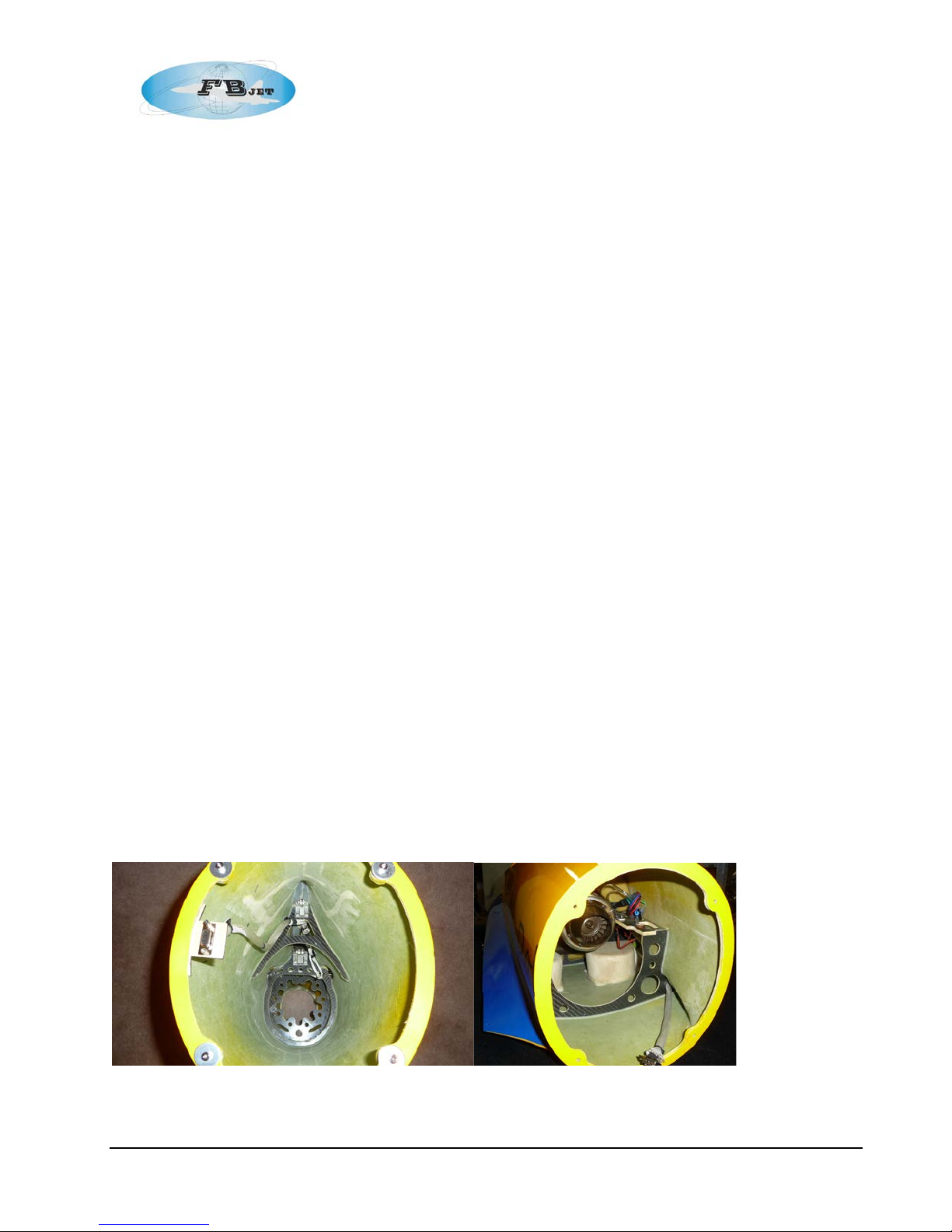
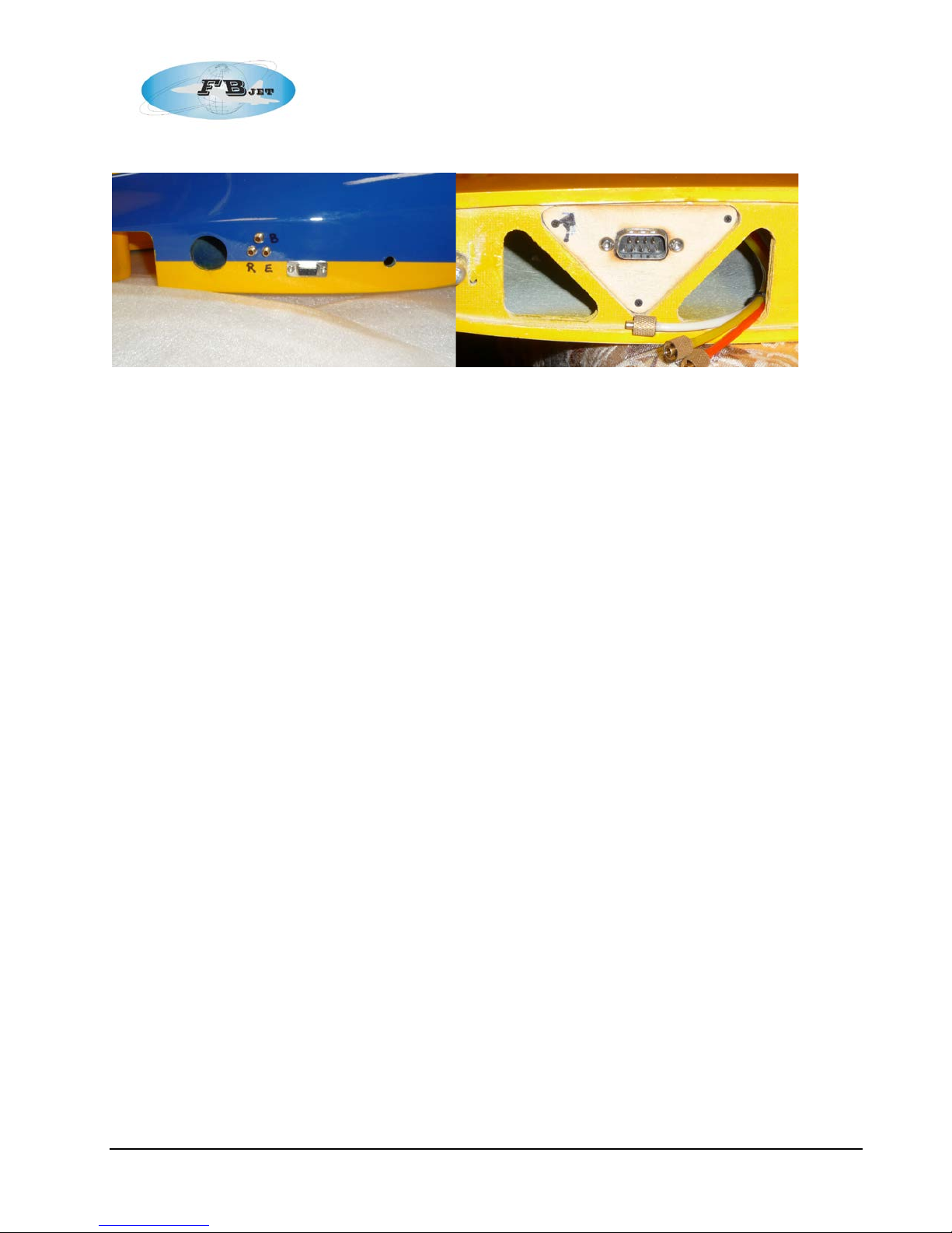
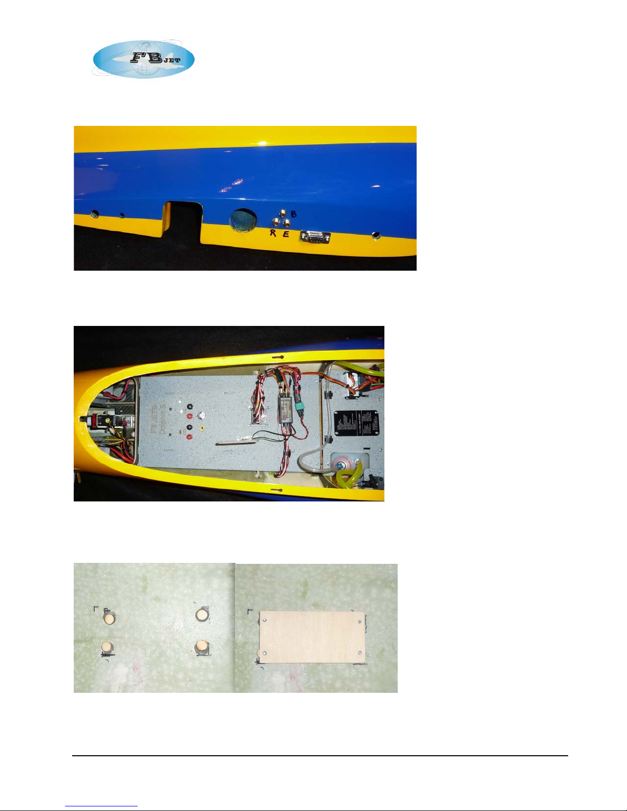
The prototype used for the cre ation of this manual uti lized a standard DB-9 “D-Type” connector
(See photo) ; however, any connector sy stem could be utilized.
Note: If using individual servo ext ensions, i t is a good idea to mark each lead with an identifier to
aid during assembly.
Aft Fuselage Front Fuselage
The proto t ype’s wing connections also utili zed DB-9 D-Type connectors for the connection of the
servos, w hen the wing i s slid onto the spar and mates with the fuselage the servo connecti ons are
made.
10
Page 11
FB Jets Dolphin S
Fuselage Ce nter Root section Wing Root sect ion
Note: any fiberglass sur faces on the inside of the airframe that requires components to be bonded
should be cleaned with mild detergent and water to make sure that any mold release agent is
removed, and then scuffed wit h medium grit sandp aper in t he area of the intended bond to
promote adhesion prior to applying the adhesive.
Pneum at ic Lan ding gear
General
The landing gear are pre-installed from the factory; it is recommended that the all retract unit s
should be r em oved and inspected for air leaks. This is easily done by submersing the retract unit
in a pan of w ater and applying pressure t o each of the cylinder inlets while maintaining pressure
see if any air bubbles are detected. If leaks are detected they sh ould be corr ected by
disasse mbling the cylinders, cleaning, and applying O-ring lube, then reasse m ble and re-test.
Check the fu nction of eac h gear wit h a hand pump or other suitable air source while they are
removed fr om the airf rame. Make sure the extension and retr action of the gear is smooth b efore
final installation. Check for free rotation of the wheels on the axels, t he wheel bushi ng will require
lubrication or even may require reaming of the I.D. of the bushings to create a better fit.
Step 1: Nose Gear
Remove nos e gear from fus elage and perform leak checks as describe above.
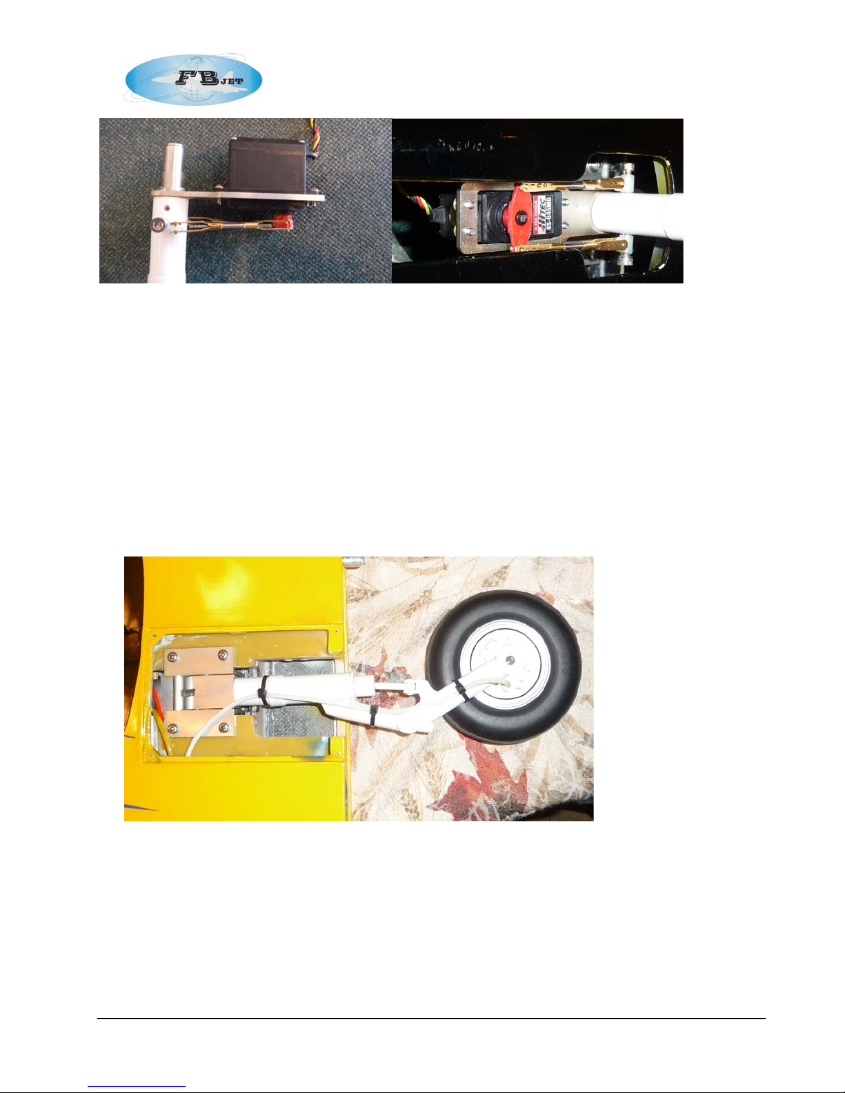
After performing the ab ove checks, a ssemble the steering servo into the nose strut steering
bracket as shown using the supplied mounting hardware. The servo is mounted from the
top side of the bracket to get better alignment with the provided holes for the strut control
horns; the servo output shaft is mounted away from the strut.
11
Page 12
FB Jets Dolphin S
Using a receiver or ser vo driver find servo neutr al and attach a suitable double sided
servo ar m perpendicul ar to the servo m aking sure t o tighten the servo arm screw .
The threade d rod supplied with the kit was 2-56 style all thread and clevises as shown
in the photos, it recom me nded to change these to 4-40 parts.
Step 2: Main Landing Gear
Remove main gear from wings and perform leak checks as describe above.
After performing the ab ove checks, reassemble the main gear back into the wings using the
supplied screws or replace with bui lder supplied optional allen head bolts and bli nd nuts.
12
Page 13

FB Jets Dolphin S
Step 3: Forward Fuselage
Once the nose gear and ser vo assembly is complet ed, install the retract unit back into the
fuselage , prior to installation pl ace a very small dab of thin CA i nto the mounti ng screw
holes first if using t he factory provided sheet metal ty pe screws.
Airline routing should be neat; it is recommended that the pneumatic valve equipment be
installed as far forward in the fuselage as possible. The pr ototype was built utili zing a Jet
Central electronic dual action valve for the retracts and a Jet Central electronic single
action valve for the brakes. Rememb er to keep equal lengths of air lines w hen creati ng the
right and left side run to the retracts and brake s to ensure even operation.
The Dolphin S is supplied with brass airline connectors, the prototype used the male end of
the fittings glued i nto the fuselage at the wing junction for easy wing connections.
The female ends were left loose with extra length of tubing protruding from the wing halves.
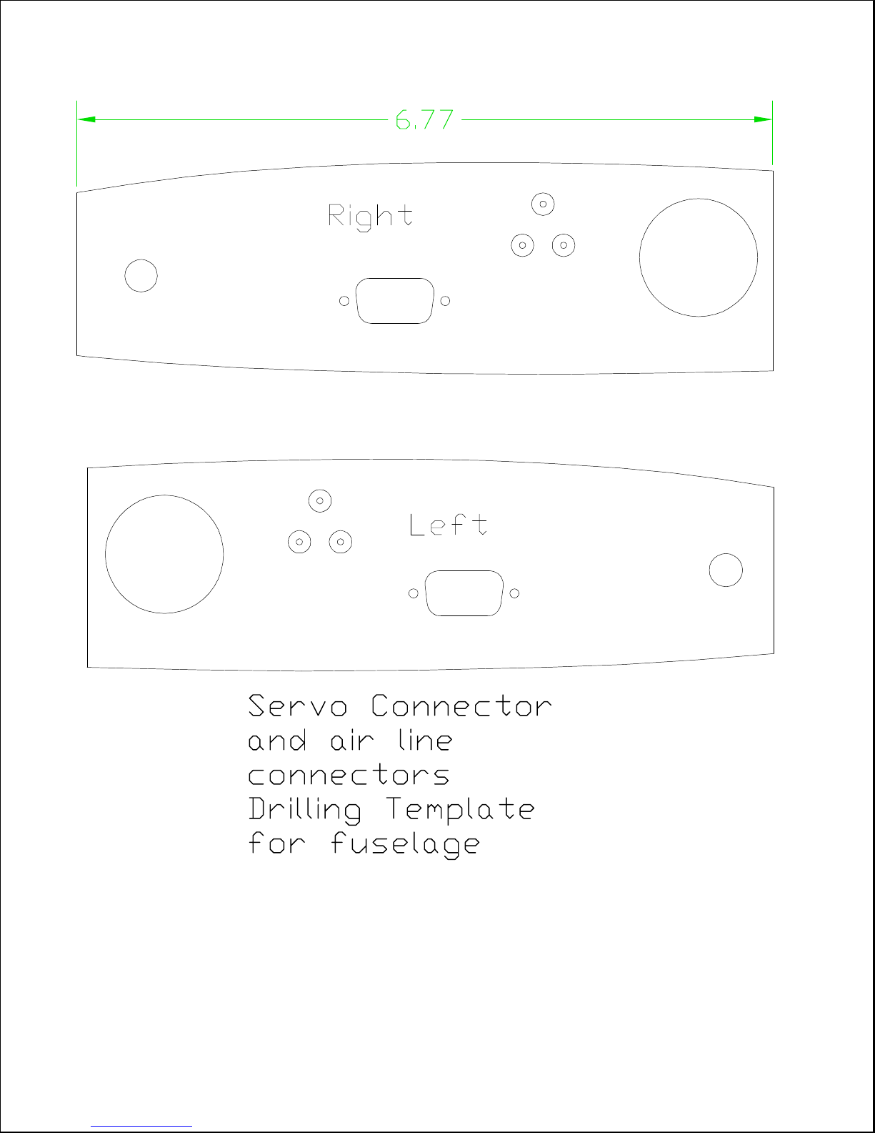
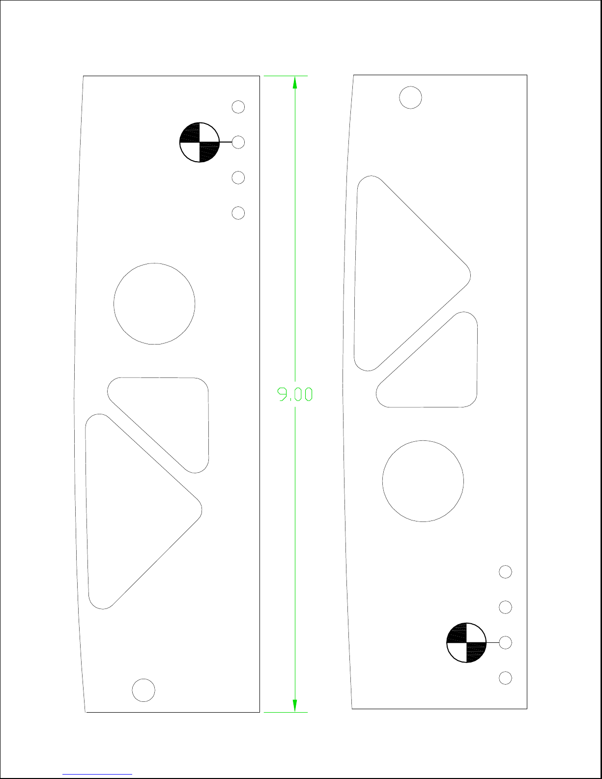
A 1:1 scal e dri lling template and C.C fixture w as created to locate the mal e connectors in
the wing root area of the fuselage and can be found in Appendix A of this manu al.
Battery Mounting
The choice of the batter y technologies to be used i s up to the builder’s discretion. The goal of the
build w as to achieve proper C.G. without the need to add dead weight. The prototy pe model
required that weight needed to be located as far forward as possible to achieve the proper C.G.
To achieve proper balance, two 5000 mAH LiPo hard case packs were used; on e for the ECU, and
one for the receiver. A voltage regulator was used to create th e required voltage level for the radio
system.
It is recommended that the batteries are mounted in a position to allow for easy removal for
charging a nd maintenance no matter what technology is used. There are many methods a vailable
to secure the batteries, a few include mounting with adhesive backed Velcro™ or using zip ties
such as ty-raps on removable mounting plates etc. It is the builder’s di scretion to provide the
proper sec urement method to ensure s afe operation, maintain proper C.G., and allow quick access
in case of battery emerge ncies.
13
Page 14
FB Jets Dolphin S
Optional Battery Box
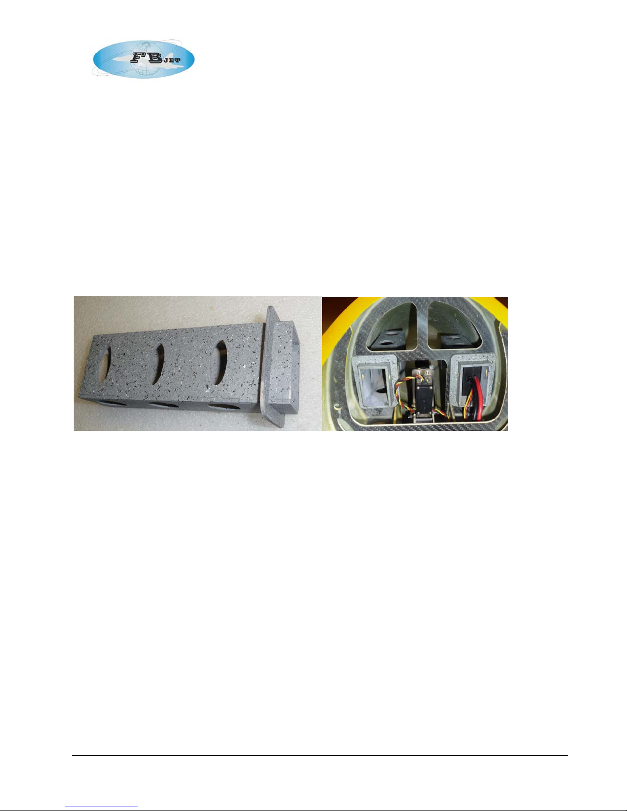
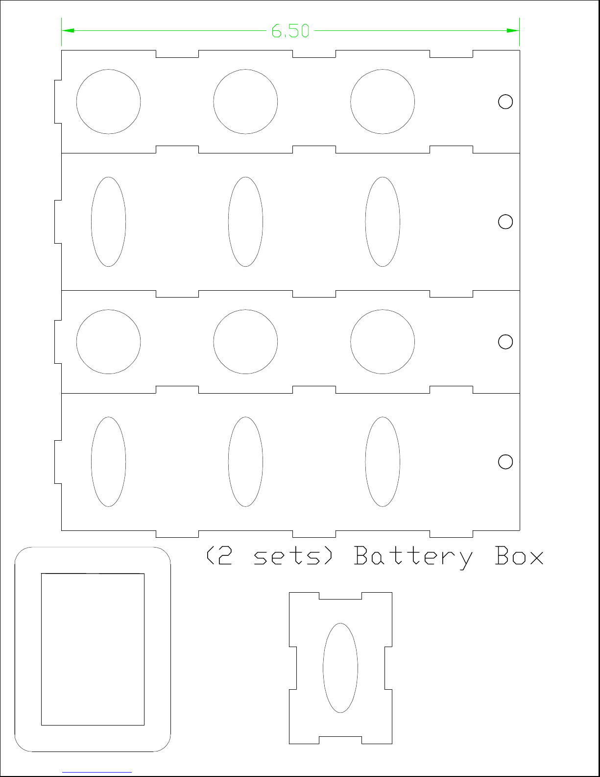
The prototype was constructed using two lite plywood batter y boxes; the se allow quick
removal of Li-Po batteries for charging and mai ntenance and provide a metho d for
achieving correct C. G. balanci ng without the need for added dead weight. The component s
can be cut from the templates in Annex A from 1/8” lite plywood. Lite-ply is very strong
when constr ucted int o shapes such as the box.
Assemble the battery boxes using CA, see photo for detail.
Trial fi t the battery box through the front former, if there i s interference open up the ar ea
using a Dre mel tool or file.
After establishing a good fit, H ysol the battery boxes in place.
The batteries are hel d in place with a ¼” wood dowel that is positioned in the f ront of the
battery box, the dowel is held in position by a small wood screw.
Step 4: Fuel Tanks
If your model is provi ded with a factory plumbed fuel tanks it is recommended that you
disasse mble and inspect the tank hardware.
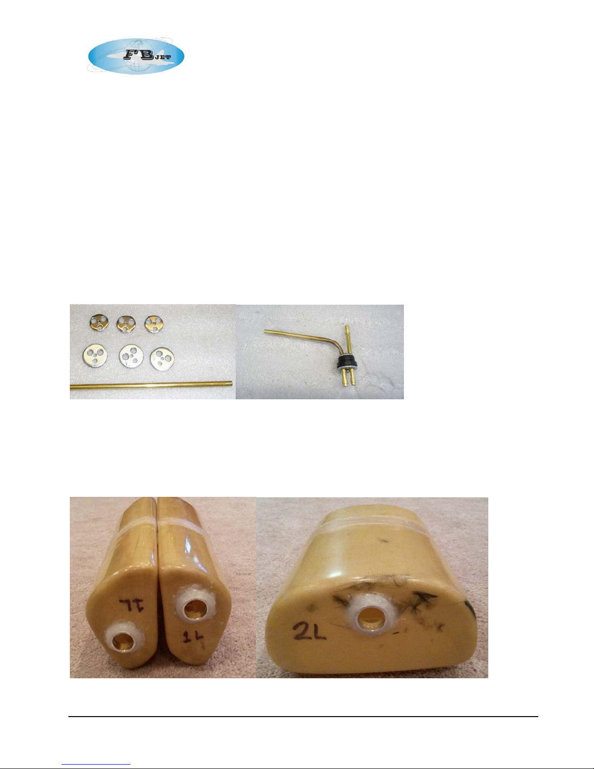
The author recommends t hat the factory supplied brass tubing should be replaced if it is not at
least 3/16” (4.76 mm) in diameter. Additionally fuel li ne barbs should be soldered t o the tubing and
this can be achieved by cutti ng ¼ ” (6mm) lengt hs using the next size of t elescoping brass tube, i.e.
7/32 (5.5 mm), this wil l prevent the fuel line from sl iding off of the brass tubing. This change will
require that the supplied metal tank fittings to be drilled to accept the larger brass tubing or can be
upgraded t o the Sullivan Aluminum stopper ki t #S478 which includes the larger 3/16” tubing. It is
also recommended to use 3/16” Tygon™ tubing or equivalent for all of the interconnect ions of the
fuel system. Finally perform a leak check on each fuel tank prior to installation; this short process
up front could save a lot of time later.
The fuel system was assembled connecting the three factory supplied tanks in ser ies, in this
configuration it is imperative th at the larger diameter tubing be used to r educe the rest riction
14
Page 15
FB Jets Dolphin S
developed in the fuel system. All fuel system lines should be pr operly inserted onto the tubing and
safety wire tied to prevent unwanted and potential ly harmful leaks.
Note: Restriction in the fuel sy stem may cause performance issue wi th your turbine such as not
allowing proper full speed RPM, abnormally high pump pulse width numbers and or excessive
stress placed on the tan ks while f ueling the model. Stress on the tank s is due to expan sion cause d
by air not venting out of the tanks fast enough during fueling. Additionally fuel restrictions or leaks
on the suction side of the fuel pump can cause cavitation, leading to air ingestion in the turbine fuel
supply , ultimately causing a flame out.
Total Fuel System Volume of the suppl ied tanks with the prot otype was 135 oz (4000 ml)
Saddle Tanks ea. : 34 oz. (1000 ml)
Main Tank: 68 oz. (2000 ml)
Larger diameter tubing and drilled out tank hardware, Fuel line barbs soldered onto the tubes
Factory supplied saddle and main tanks.
15
Page 16

FB Jets Dolphin S
Tank A ssembly
When working with brass tubing components pl ease follow the steps outlined below:
Use a small , round file or a #11 X-act o knife to remove the excess metal inside of the cut
ends of the tubes. You wil l need to inspe ct the ends of all tubes. Another good method is
to use a count ersink tool to de-burr the tubing, as you want to create an internal chamfer.
Make sure to install fuel line barbs, checking the ends of the brass tubing to m ake sure any
sharp edges are removed that could potentially cut the T ygon tubing causing leaks.
When finished, make sure to blow out any metal f ragments that may have been left behind
and clean up any sharp edges.
While t he components are apart, or re-fitting with new l arger tubing, check the fuel pickup
line for equal lengths in both saddle tanks. T hey should be l ong enough to reach t he back
of the tanks without being so long as to restri ct their ability to move to the top of the tank
when the ai rcraft is i nverted.
Make sure the bends creat ed for the vent tubes have not restricted airflow to any signi ficant
extent.
Check the Tygon for any ni cks or cuts, se cure to the tubing with safety wire to the fuel
clunks and the pick-up tube.
If the aluminum tank bung f ittings have not been fitted to t he tanks, the tanks will need to be
prepared. Make sure the entrance hole is large eno ugh for the bun g. Sand the tank in the
area where t he bung will be fitted. It is a good idea to drill a seri es of small holes around
the periphery of the aluminum bung flange to promote securement of the ad hesive. Finally
using Hysol, glue the bun gs to the tank s allow time for a complete cure before proceedi ng
with the completi on of the tanks.
Once the tanks are back together, they should be leak checked b efore installation i n the
aircraft. Connect extra lengths of f uel tubing to the fuel and vent lines and submerge the
tank in w ater. Pinch off one line and gently pressurize the tank by blowing into the other,
looking for signs of air bubbles. If the tank shows evidence of air leakage around the vent
cap, tighten the screw and check again. If the fiberglass weave is leaking; repair wi th Hysol
or epoxy or apply a lay er of glass cloth and epoxy resin.
16
Page 17
FB Jets Dolphin S
Tank Mounting
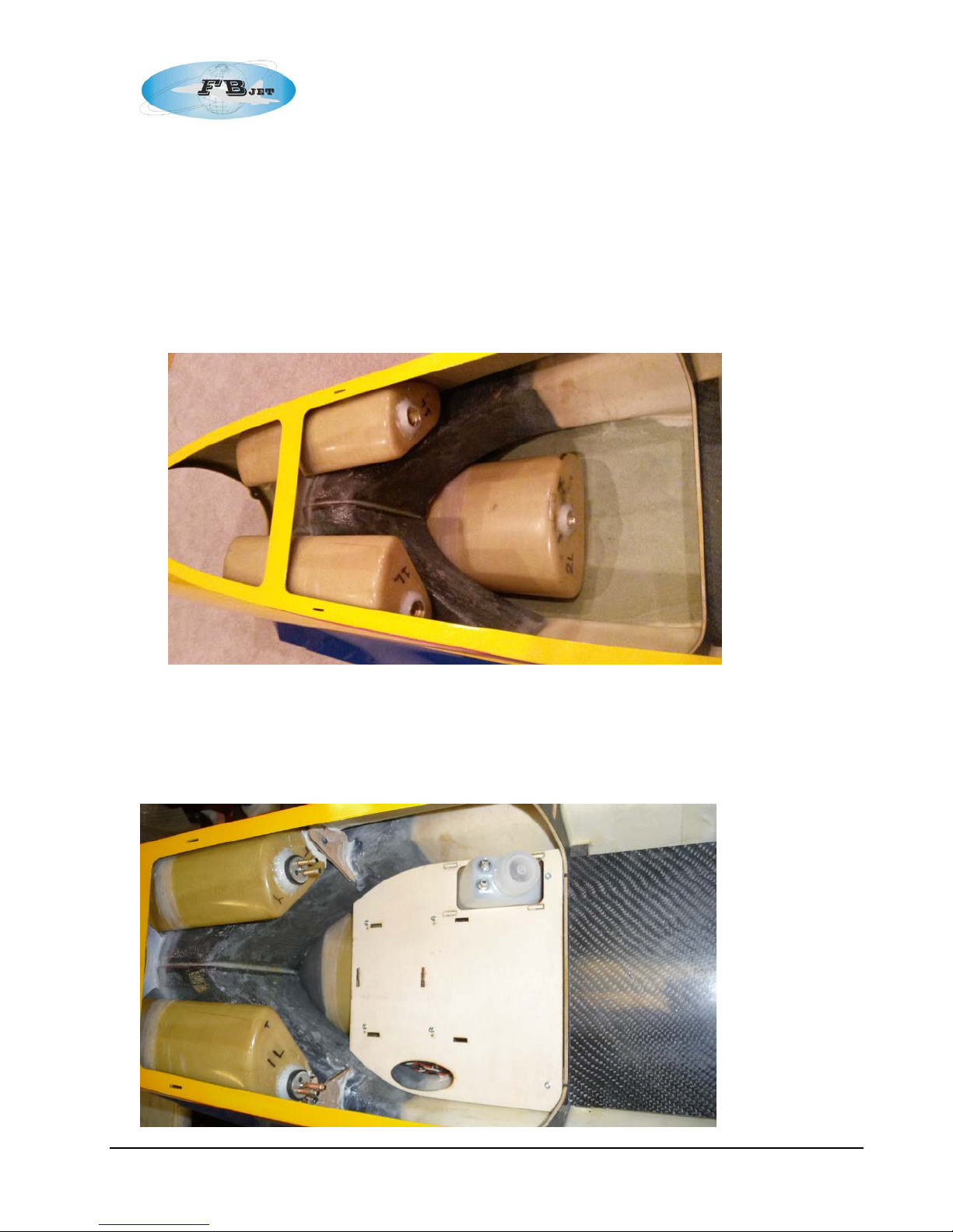
It is recommended that the fuel tanks ar e mount ed to allow f or removal for future maintenance.
There are many methods available to secure the tanks, a few include mounting with adhesive
backed Velcro™ or tack glue using a few dobs of RTV.
Saddle Tanks:
The main and saddle tanks are located as shown; it is the builder’s di scretion to provi de the
proper securement method to ensure safe operation.
Optional Mounting:
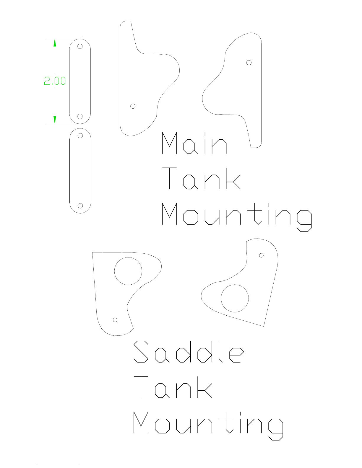
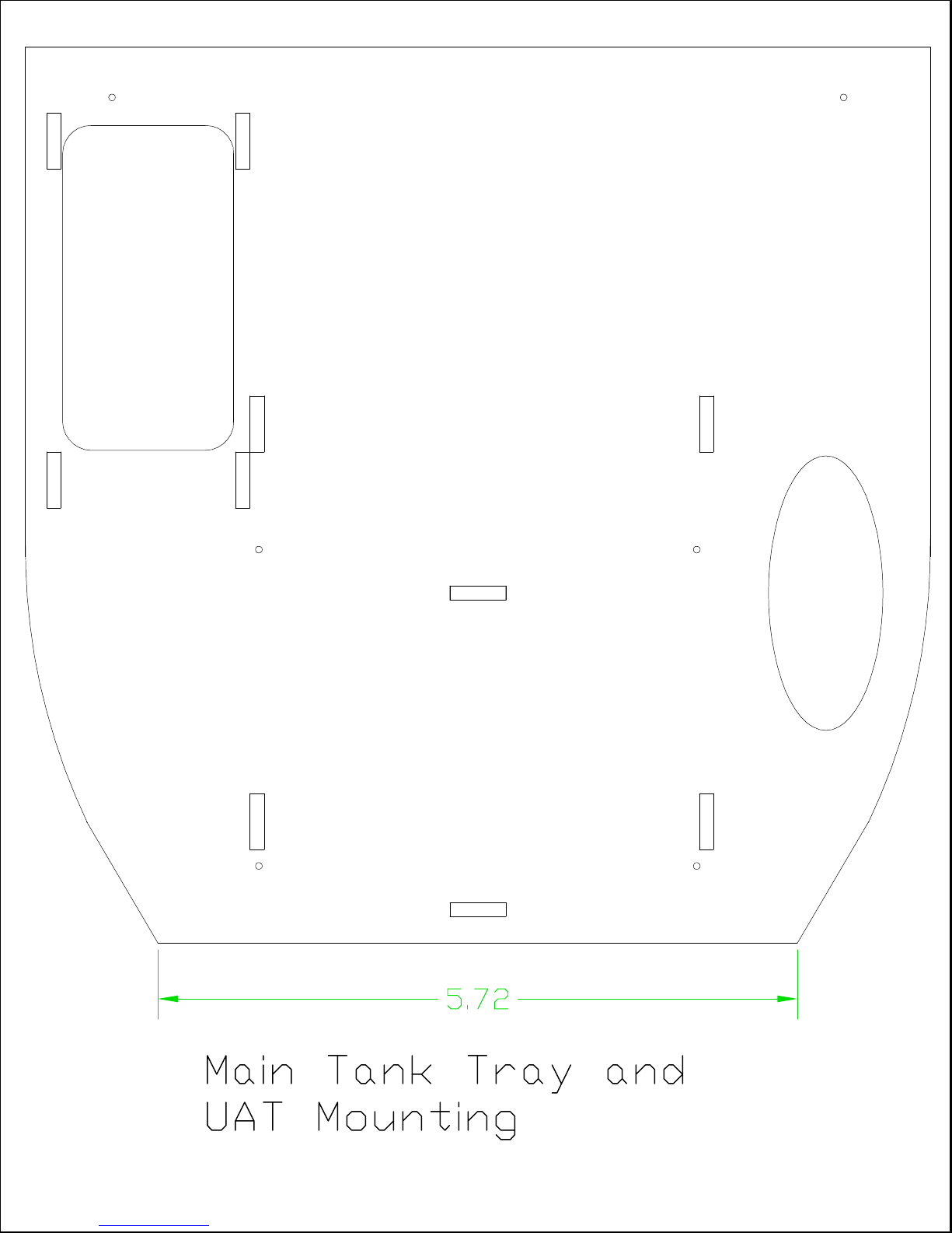
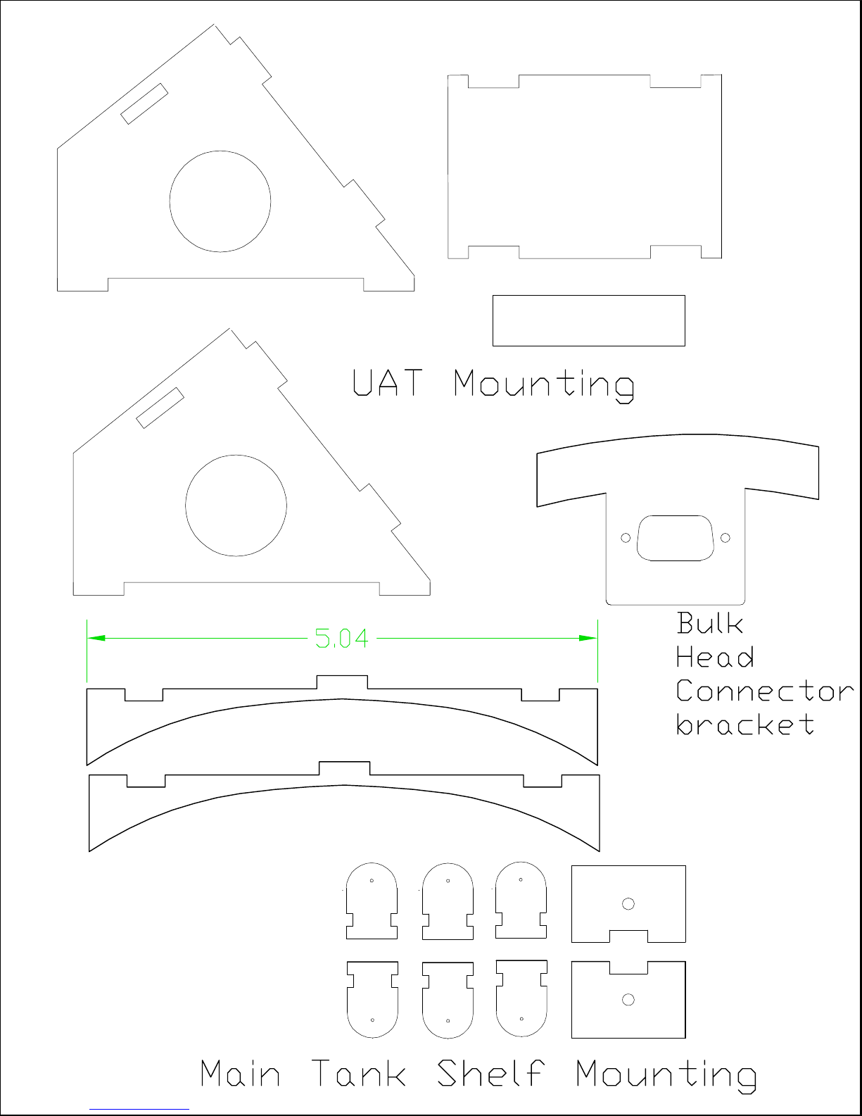
The method used for the prototype utilized ply wood mounting brackets; templates shown in
Annex A may be used to fabricate the m. If this mounting method is desi red the foll ow ing will
guide you through the steps.
17
Page 18
FB Jets Dolphin S
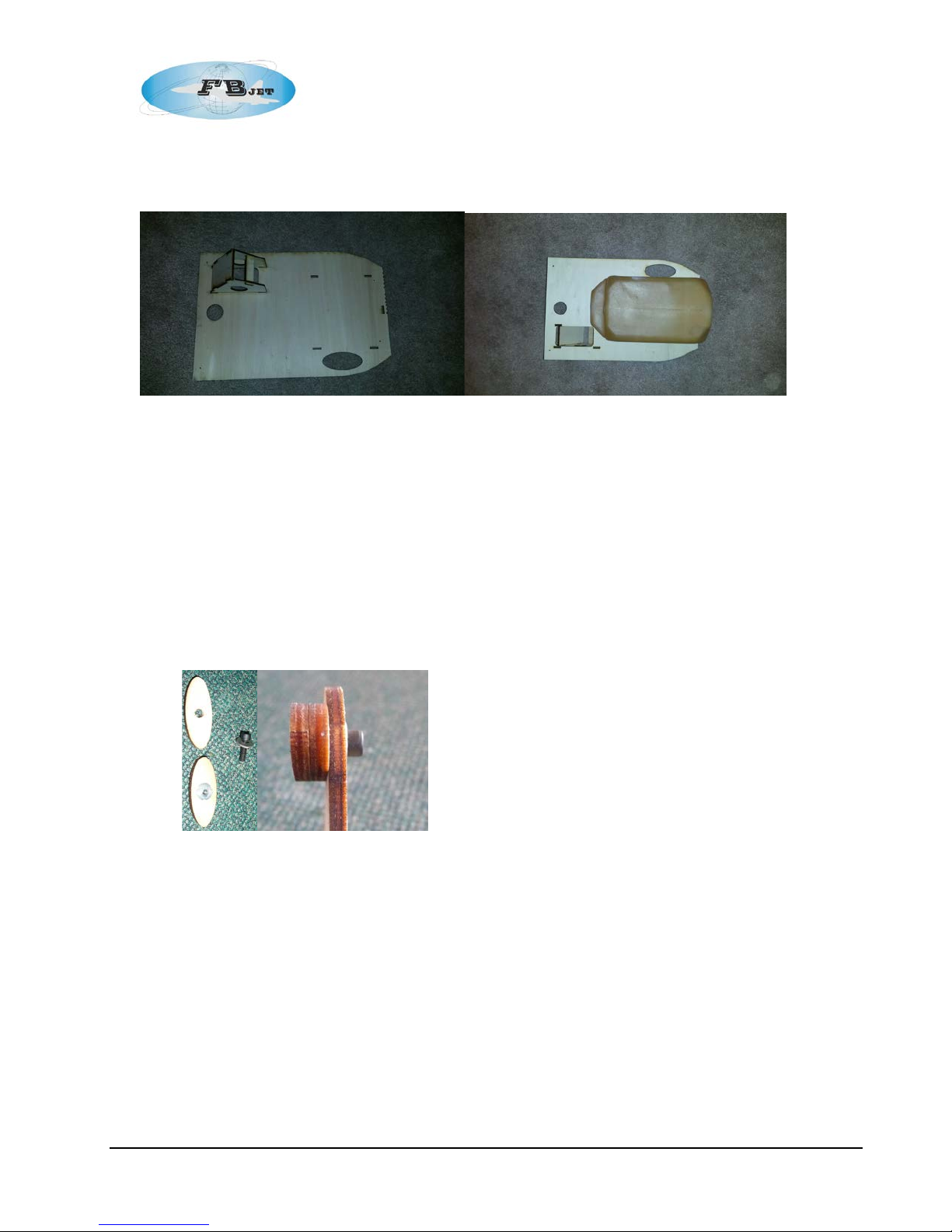
UAT / Optional Smoke Tank Tray
The tray features an integral UAT holder and provides a surface to mount an opt ional smoke
tank.
The plywood tank holders shown can be fabricated from the supplied template in Annex A
utilizing 1/8” (3mm) plywood. The saddle tanks use a mount on the f ront of the tank to
secure the m.
Trial fit the saddle tanks a s shown in the above photo sequence, mark the area on the front
of the tanks where the front plywood mount pads will be positioned, and also mark the area
on the fuselage where the f ront fuselage saddle tank mounts will be posi tioned. Sand the
areas wi th medium grit sand paper.
Install a blind nut i nto the tank mount p ad, a second tank mount pad will be used for a
spacer, glue the two pads t ogether and then bol t the tank mount pad to the main tank
fuselage mount. Make sure that the bolt does not pr otr ude past the ba ck sur f ace of the
blind nut, if so file/grind to flush as this surface will be glued to the sad dle tank.
Position the saddle tanks to thei r final place.
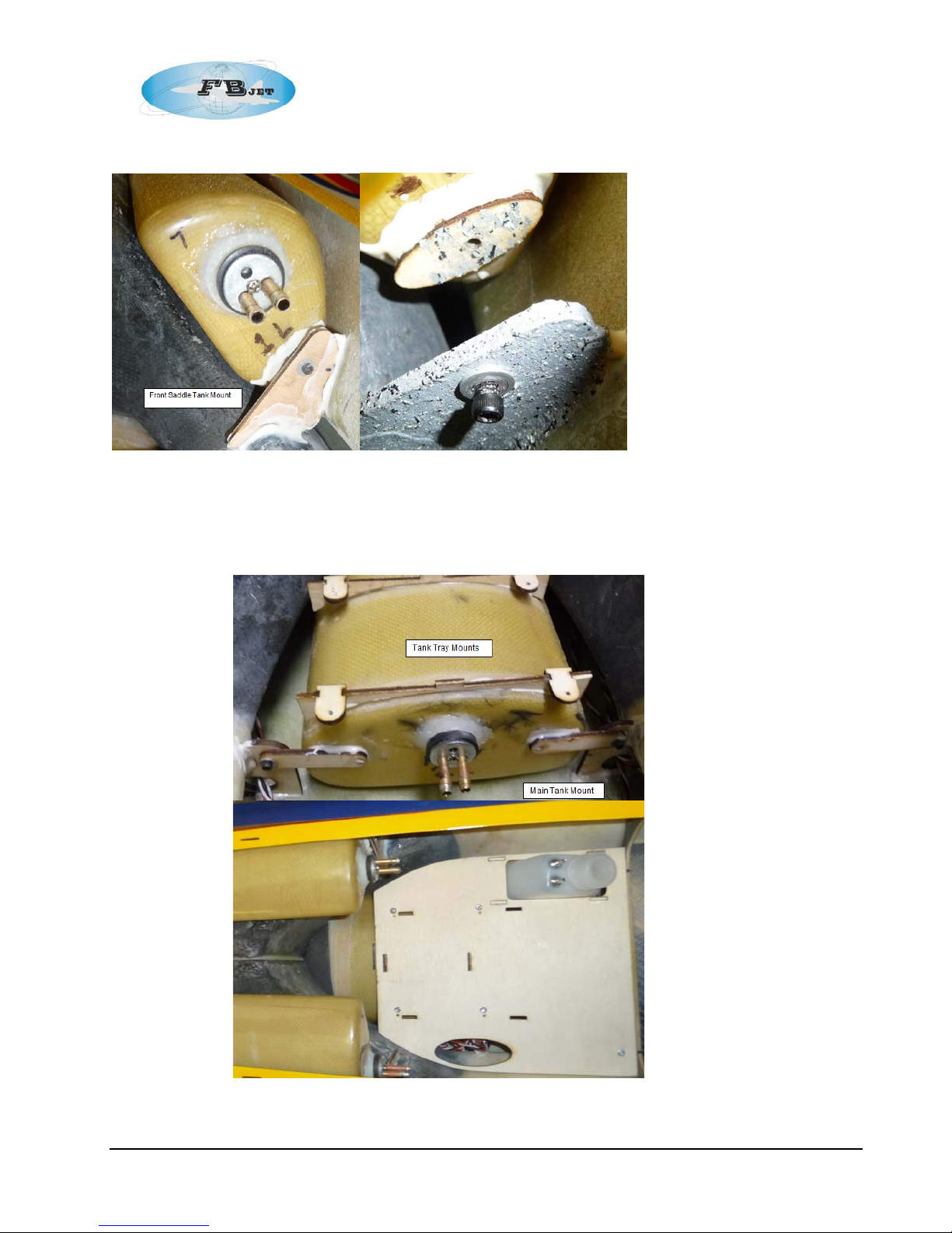
Apply Hy sol to the fusel age former tank mount and to the back side of the tank mount i ng
pad that is bolted to the fuselage mount . Position the fusel age mount int o the fuselage
making sure the pad is in contact with the front sur face of the tank, let dry, see photo.
Repeat step f or the other saddle tank, let dry.
Once the gl ue is dry the bolt can be remo ved to allow the tank to remo ved for service work,
see second photo.
18
Page 19
FB Jets Dolphin S
Front Saddle Tank Mount
Main tank brackets & UAT / (Sm oke Tank) Tray
19
Page 20
FB Jets Dolphin S
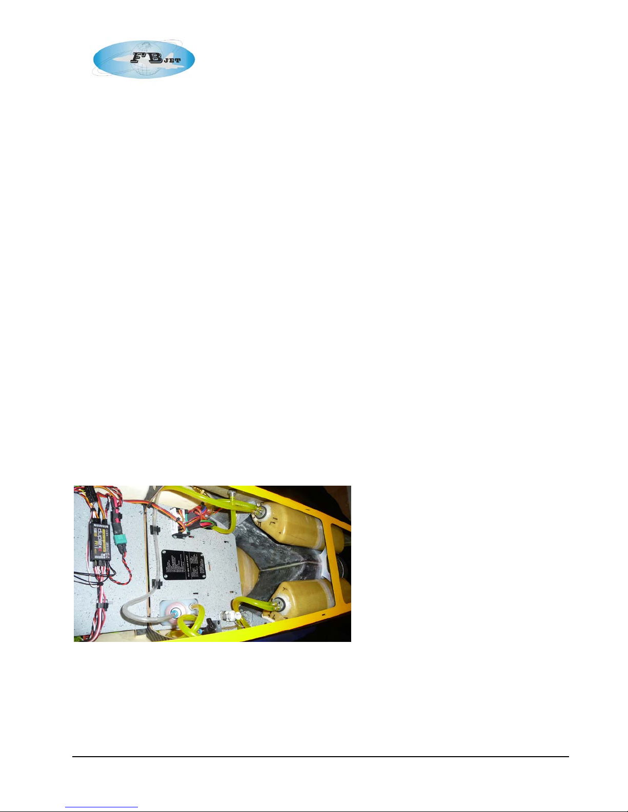
The main tank mounts and UAT tray (Smoke Tank Mounting tray) can be fabricated
from the sup plied templates in annex X utilizing 1/8” (3mm) plywood.
Trial f it the main tank as shown previously in the above photo sequence, mark the area on
the front of the main tank where the two plywood mounting straps wi ll be positioned, also
mark the are a on the fusel age where the f ront fuselage main tank mounts wil l be
positioned. Sand the are as with medium grit sand paper.
Install a blind nut i nto the back side of the main tank m ount, bolt the tank mount ing straps
to the mai n tank fuselage m ount.
Position the main tanks to its final place.
Apply Hy sol to the fusel age former main tank mount a nd to the back side of the tan k
mounting strap that is bolted to the fuselage main tank mount . Position the fusel age m ount
into the fuselage maki ng sure the tank strap is in contact with the front surface of the main
tank, let dry, see photo above.
Repeat step f or the other m ain tank mount and strap, let dry.
Once the gl ue is dry the bolt can be removed t o allow the tank to removed for ser vice work.
Step 5: Final Fuel System plumbing:
Starting with the UAT, the supply line to the UAT is connected to the clunk line of the left
saddle t ank,
The vent li ne from the left saddle tank is connect ed to the cl unk line of the main tank,
The vent li ne from the main tank is connected to t he clunk line right saddle tank,
The vent li ne from the right saddle tank is connected t o the vent fitting that exits the
fuselage.
The check valve fuel filler in connected to the other UAT fitting for system fueli ng.
The center line from UAT is connecte d to the fuel pump.
Make sure to safety wire all connections at this ti me.
If you use plastic wire ties (Ty-raps) to bind the fuel tubes t ogether for a neater i nstallation,
make sure not to over-tighten and pinch down on the flexible fuel tubing.
20
Page 21
FB Jets Dolphin S
Step 6: Air Tank Installation
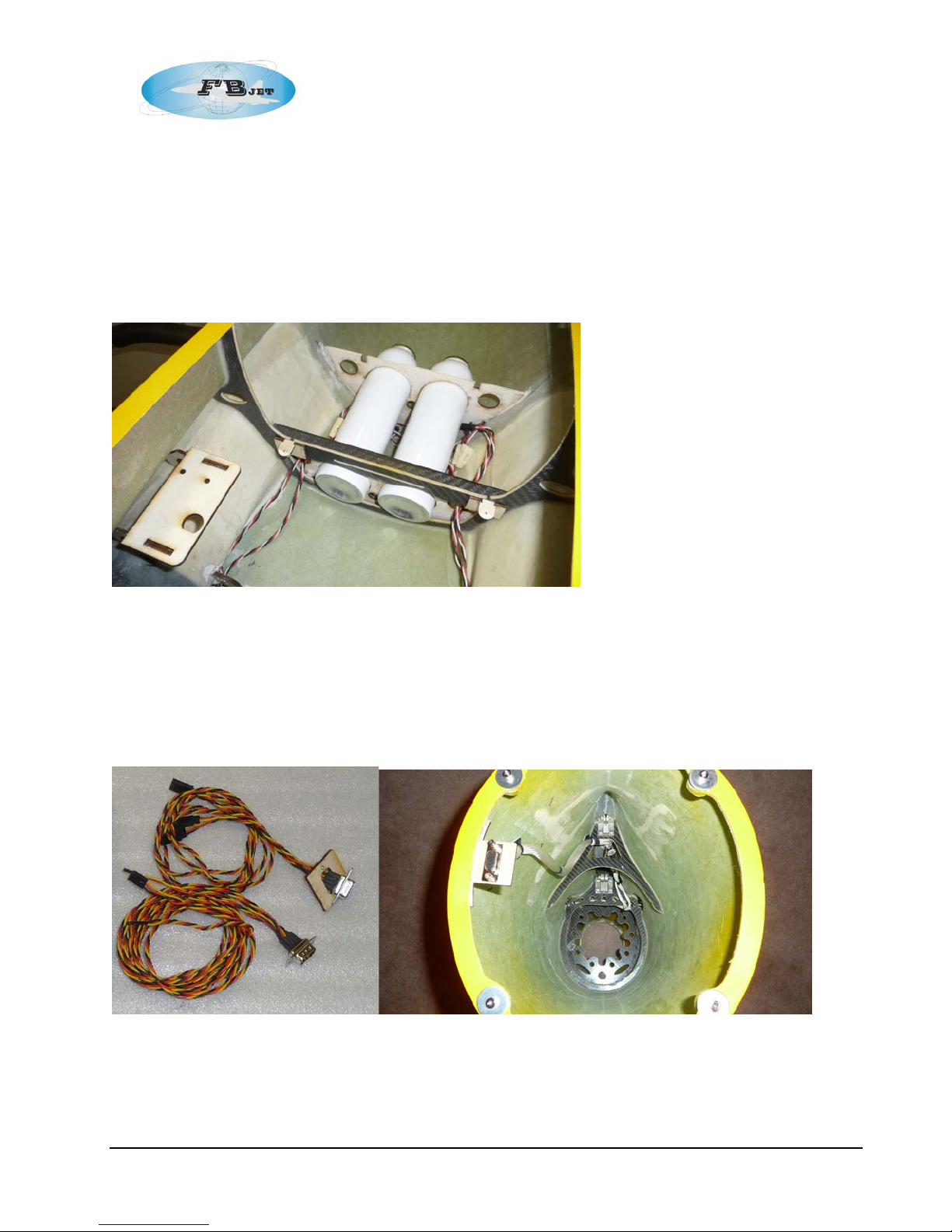
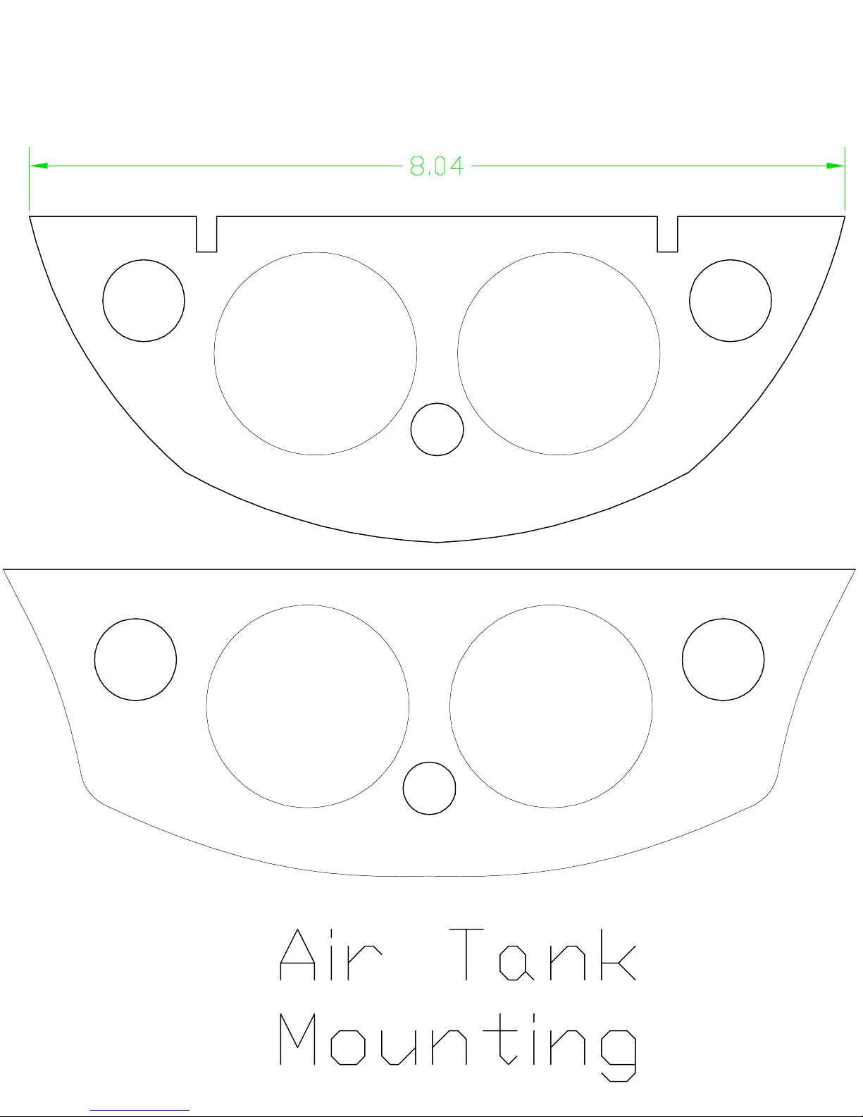
The air tanks can be installed in various locations in the airframe, the locat ion used in the prototype
was in t he area below the f ront tray using formers cut from 1/8 (3 mm) plywood) see photo. There
are many methods available to secur e the air tanks, a few include mounting with adhesive backed
Velcro™ or tack glued in place with RTV, RTV was used in the prototype and can be cut in case
the tanks ne ed to be removed for service.
Step 7: Aft Fuselage
The aft f uselage section is complete from the f actory wi th all of hardware install ed, the only item
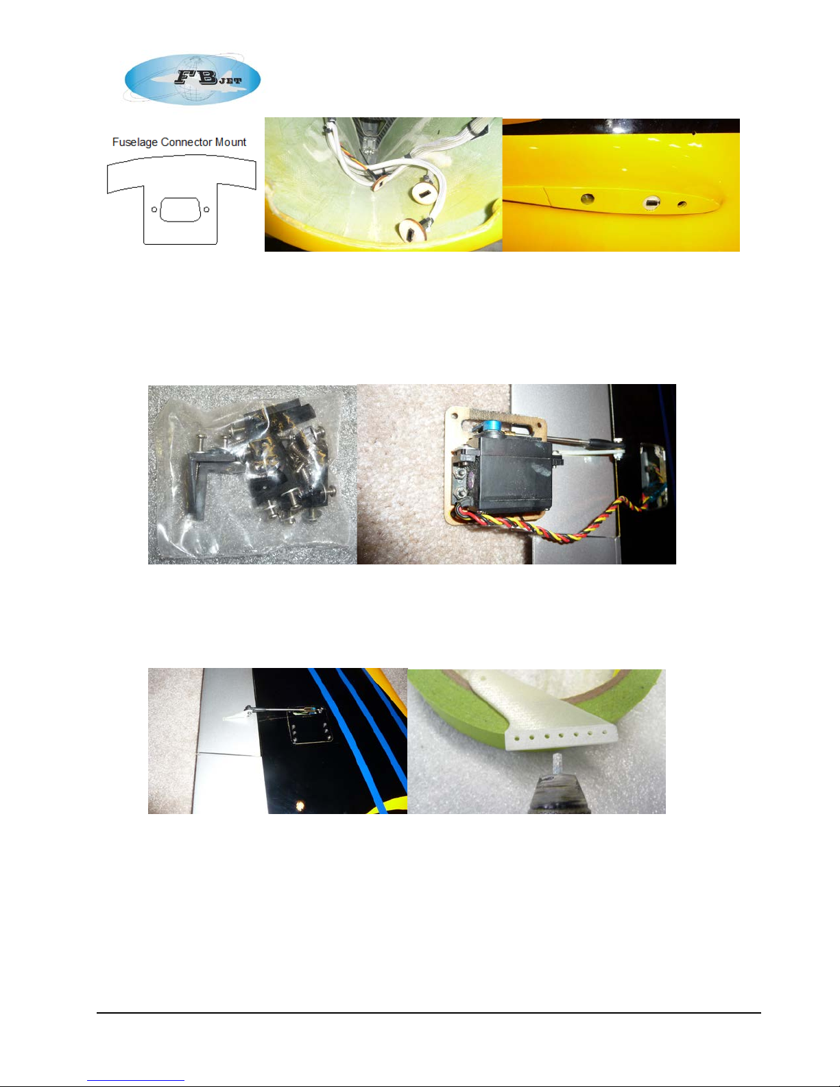
left to t he builder is the install ation of the builder supplied wiring harness and if desired an o ptional
connector bracket, see photo, the templ ate for the bracket is in Annex A.
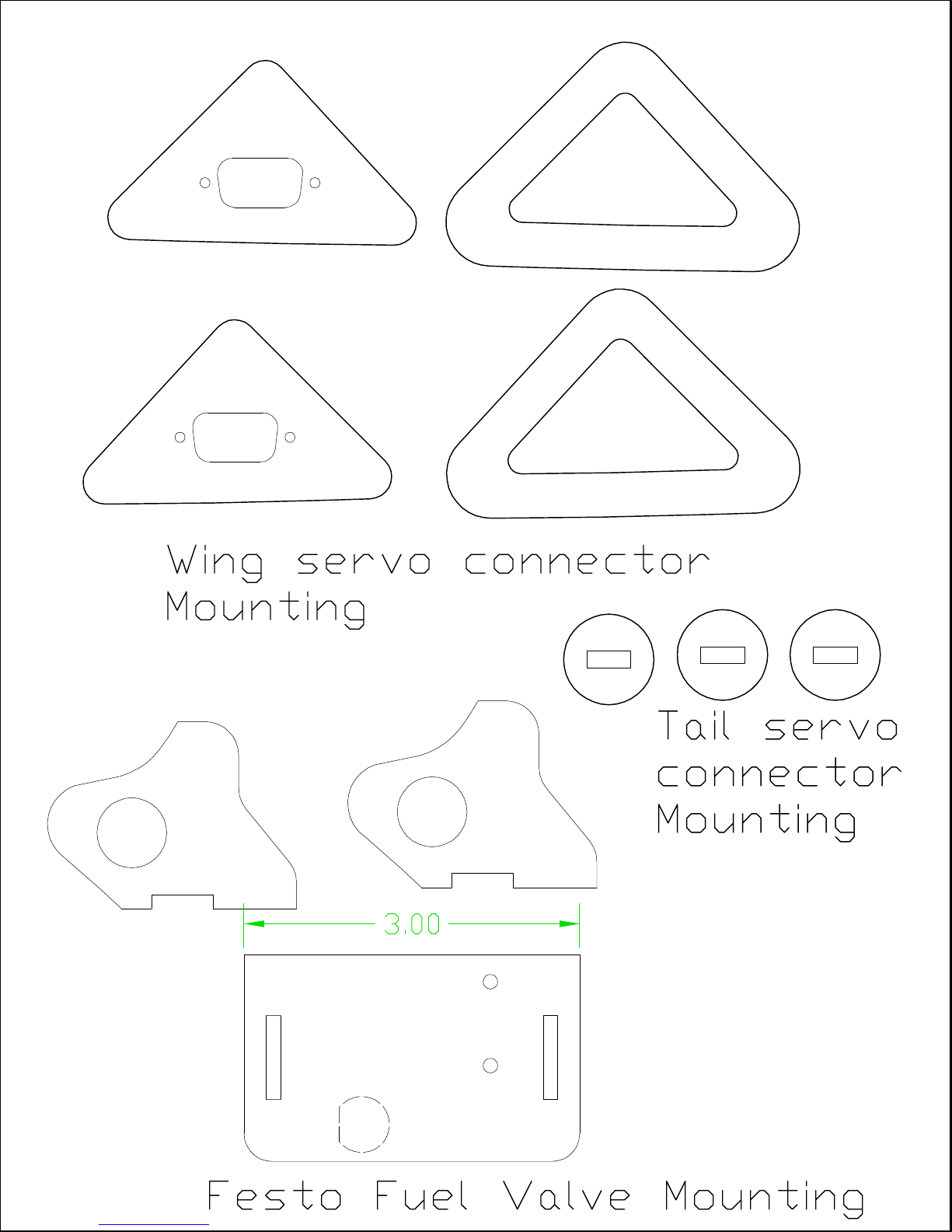
The female servo connectors were cemented into plywood disks and cem ented into the circular
cutouts in the fuselage for easy connections.
21
Page 22
FB Jets Dolphin S
Step 8: Wing – Servo Installation
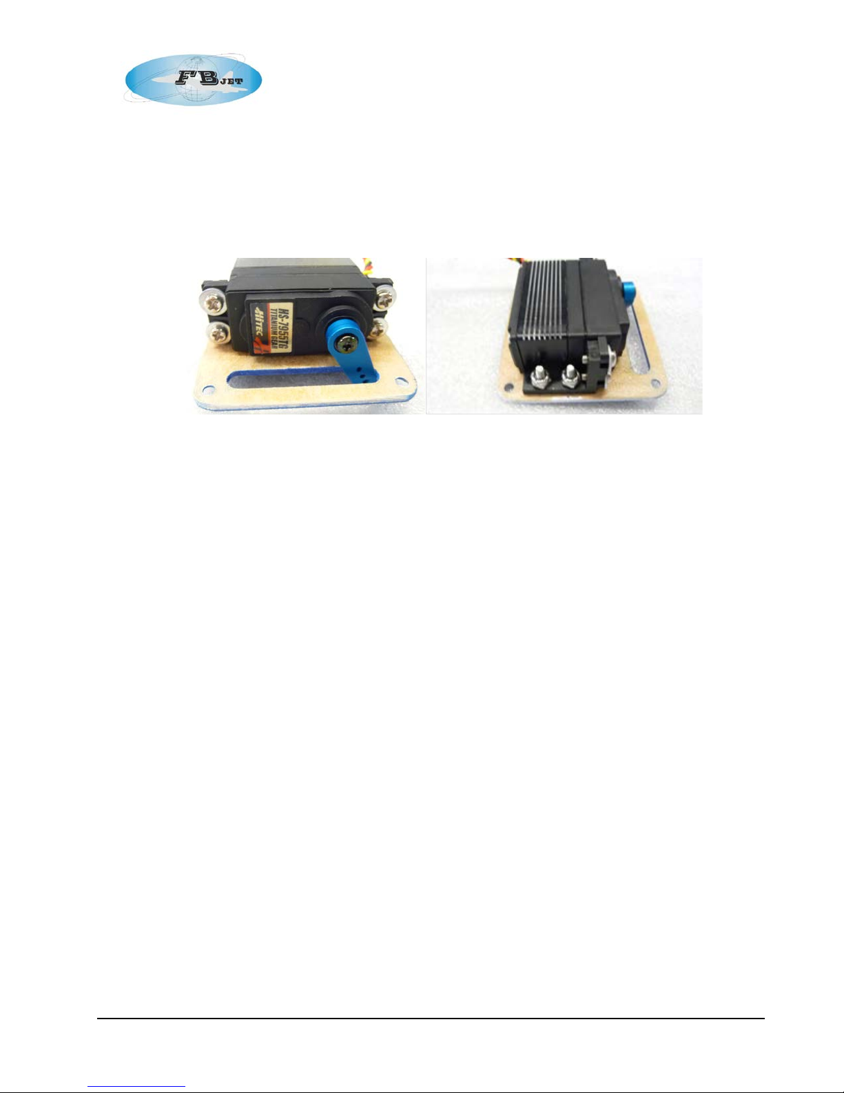
The two wing halves are supplied with two pre-slotted servo hatches, eight “L” mounting
brackets, an d mount i ng hardw are.
The Flaps and Ailerons have slots pre-cut into the surface for the fiberglass control horn.
The horn should be glued in with Hysol, before doing so m ake sure to use medi um grit
sand paper or dremel tool to roughen up the area on the horn where the adhesive will make
contact.
A uniform ad hesive fillet should be created aroun d the control horn and the control surface.
It is helpful to use masking tape around the periphery of the control horn slot. Any extra
adhesive sh ould be removed. Let the con trol horn adh esive setup u ndisturbed b efore
proceeding.
The spline of the aileron servo will face towards the wing tips and closest to the leading
edge of the wing,
The spline of the flap servo will face towards the wing tips and closest to the leadi ng edge
of the wing.
22
Page 23
FB Jets Dolphin S
It is not recommended to use the rubber g rommets supplied with the servo for the mounting
into jet airframes as vibrations typicall y asso ciated with recipr ocating power plants are not
an issue.
Using a receiver or ser vo driver, find servo neutral and attach a suitable single sided servo
arm perpendicular to the servo making sure to tighten the servo arm screw.
Attach the L brackets to the servos, an d then bolt the assembl y to the hatch using the
provided h ardware, making sure to follow the orientation described in the above steps.
Assemble the Aileron linkage; the l inkage should measure 3 3/4” (95 mm) in length from
center to center of the ball link and clevis.
For the Aileron servo, the clevis should be connect ed to the hol e in the horn that is closest
to 25/32” (20 mm) from center of the spline.
Assemble the Flap linkage, the linkage should be 3 3/4” (95mm) in length f rom cent er to
center of the clevis and the ball link.
For the Flap servo, the clevis should be connected to the hole in the horn that is closest to
.525” (13 mm) from center of the spline. Make sure to use keepers on the clevis.
Pull the servos extensions through the wing to t he roots; label the servo wires for Ailerons
and Flaps. It is recommended to use servo keeper clips when make connections to the
extensions.
Repeat proc edure for t he other wi ng.
When complet ed check the operation of the ailerons and flaps to m ake sure that there is no
binding.
23
Page 24
FB Jets Dolphin S
Step 9: Vertical fin and rudder servo installation
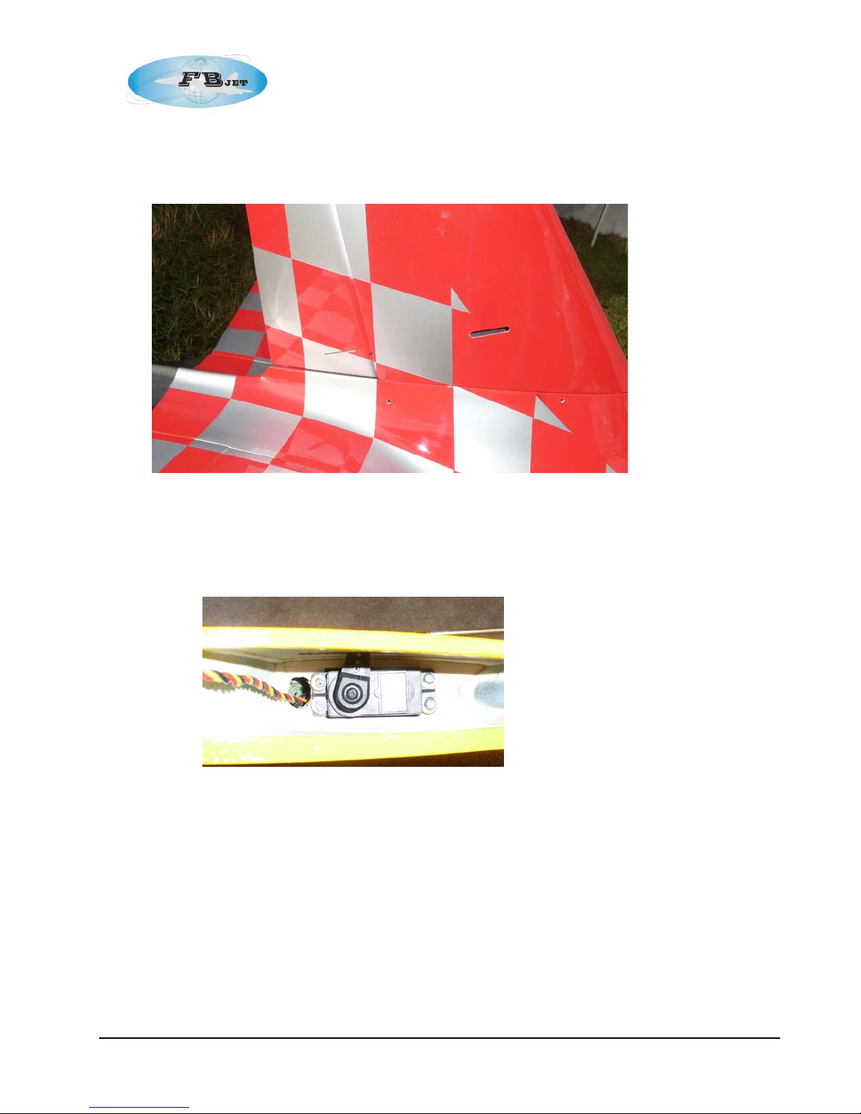
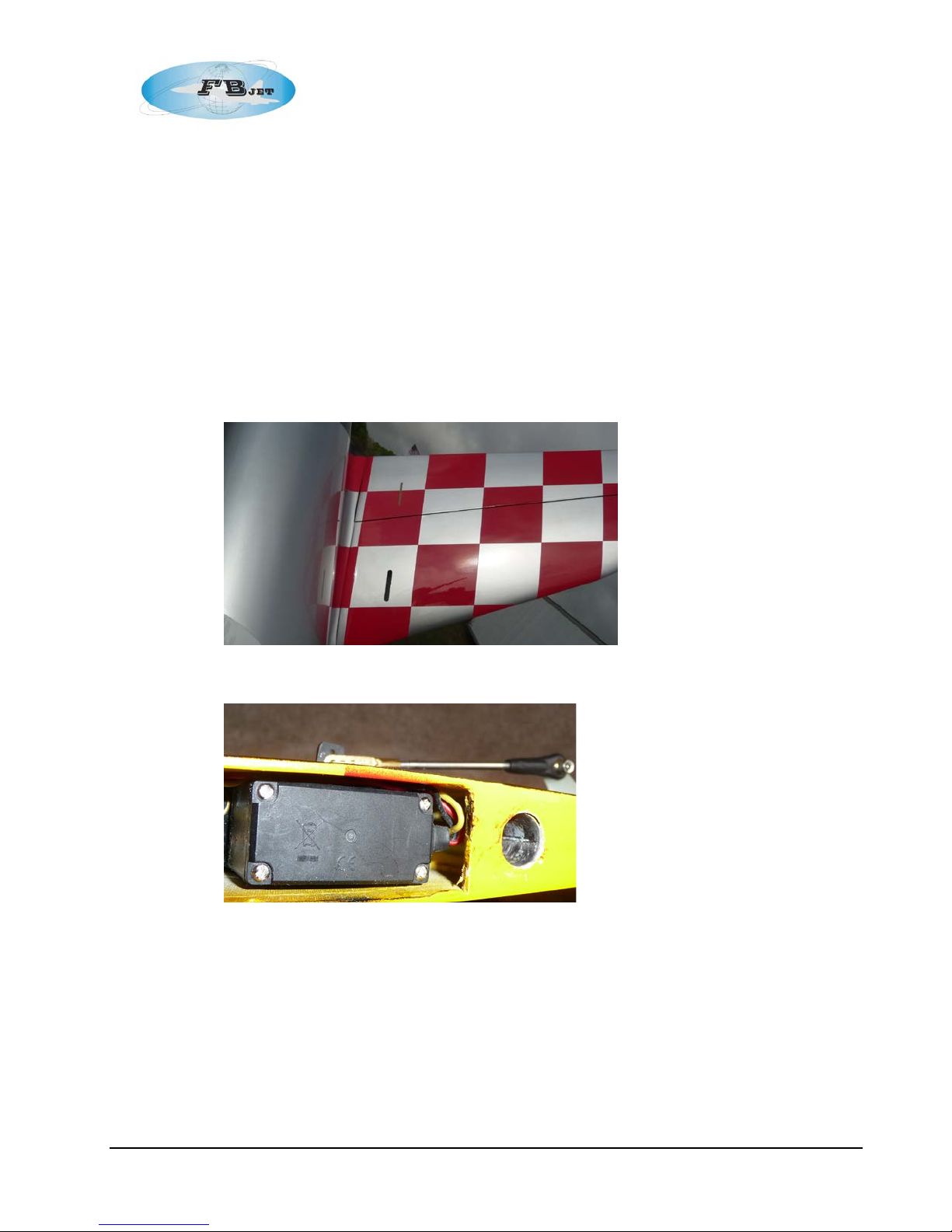
Production models have the servo slots and the cont rol horn slots precut as shown
The servo is installed in the fin with the spli ne of the rudder servo facing towards the base
of the fin and closest to the leading edge. It is not recommended to use gro m m ets for servo
mounting into jet airframes as vibrations typically associated with reciprocating power
plants are not an issue. It may be required to create a servo wire access hole in the mount,
see photo.
Use sheet metal type servo screws to mo unt the servo, after installing t he screws, remove
them and apply a drop of thin CA to each of the holes to reinforce the plywood, reinstall
screws after the CA set s up.
Prepare to glue in the control horn, the horn should be glued in with Hysol, before doing so
make sure to use medium grit sand paper or a Dremel tool to roughen up the area on the
horn where t he adhesive will make contact.
A uniform ad hesive fillet should be created aroun d the control horn and the control surf ace.
It is helpful to use masking tape arou nd the peri phery of the control horn slot. Any extra
adhesive sh ould be removed. Let the control horn adhesive setup undisturbed before
proceeding.
Using a receiver or ser vo driver, find servo neutral and attach a suitable single sided servo
arm perpendicular to the servo making su re to tighten the servo arm s crew.
24
Page 25
FB Jets Dolphin S
Assemble the rudder linkage; the linkage should measure 4.5” (114 mm) in length from
center to center of the ball link and clevis.
The clevis should be connected to the hole in the horn that is ¾” (19 mm) from ce nter of the
spline.
Make sure to use keeper s on the cl evis. If using the ball link on the control horn
end, make sure to use the ny-lok type nut on the bolt.
Note: you may need to enlarge the h ole in the control horn with a .118” (3 mm) drill for the
connecting bolt, do not oversiz e the hole as this will lead to linkage slop. Do not over
tighten this bolt as it could cause linkage binding.
Trial fi t the fin to the fuselage; secure both of the clamp bolts on the fin.
Check operat ion of the rudder to make sure that there is no binding.
Step 10: Horizontal Stabilizer and Elevator servo installation
Production models have the servo slots and the cont rol horn slots precut as shown
The servo is install ed in the horizontal stabilizer wit h the spline of the servo facing t owards
the tip of the stabili zer and closest to the trail ing edge.
Use sheet metal type servo screws to mount the servo, after installing the screws, remove
them and apply a drop of thin CA to each of the holes to reinforce them, reinstall screws
after the CA sets up.
Prepare to glue in the control horn, the horn should be glued in with Hysol, before doing so
make sure to use medium grit sand paper or a Dremel tool to roughen up the area on the
horn where t he adhesive will make contact.
A uniform ad hesive fillet should be created aroun d the control horn and the control surf ace.
It is helpful to use masking tape arou nd the peri phery of the control horn slot. Any ext ra
25
Page 26

FB Jets Dolphin S
adhesive sh ould be removed. Let the control hor n adhesive set up undistur bed before
proceeding.
Using a receiver or ser vo driver, find servo neutral and attach a suitable single sided servo
arm perpendicular to the servo making sure to tighten the servo arm screw.
Assemble the elevator linkage; the linkage sho uld measure 3.45” (88 mm) in lengt h from
center to center of the ball link and clevis.
The clevis should be connected to the hole i n the horn that is ¾” (19 mm) from center of the
spline. Make sure to use keepers on the clevis. If using the ball link on the control horn
end, make sure to use the ny -lok type nut on the bolt.
Note: you may need to enlarge the hol e in the control horn with a .118” (3 mm) drill for the
connecting bolt, do not oversize the hole as thi s will lead to linkage slop. D o not over
tighten this bolt as i t could cause linkage binding.
Trial f it the horizontal stabilizers to the fuselage; checking the f it of the sec urement bolt.
Check operat ion of the elevators to make sure that there is no binding.
Step 11: Equipment Installation
There are many possibilities f or mounting equipment into your airframe and it is up to the builder to
determi ne the best installation technique f or their application.
The pneumatic retract system in the model used to write thi s manu al was operat ed utilizing the
optional Electronic valves. The dual action valve operates th e retracts, and the single action valve
operates the brakes. The receiver is positioned on the main tray with the electronic pneumat ic
valve equipment mounted directly below the main tray on the fuselage floor.
The layout of compone nts is shown in the photo. This arr angement all ows easy access, pr ovides
good separat ion between t he turbi ne and receiver electronics and sits low enough for t he cockpit
to easily fit on top.
Addit i on com po ne nt l oc ati on s f or a nci l l ary de vic e s suc h a s th e ECU, fuel shut off valve, etc. to name
a few can be accomplished using mounting plates glued to the fuselage in positions where space
allows.
Now is a go od t i me t o co mplete in st al l at i on of al l ser vo ex te nsi o n s, airli nes and turbin e el ect r oni c s
throu gh t he f u sel a g e.
The prot ot y pe us e d ai r li ne f i t ti ng su p pl i ed w it h th e ki t m ounted in t he w i ng root ar ea of th e f us el ag e,
the airl ine con nect or s from t he w i ng w ere left l oos e i n t h e wing to al l ow con ne ction to t he r i dge d
mounte d fu s el ag e c onn e ctors.
26
Page 27
FB Jets Dolphin S
Airline conne ct or s l ocated i n fu sel a ge r o ot sect i o n al o ng w i t h builder s up pl ied D-type servo
connector.
Front eq uip ment tr ay
Locati on for ele ct ro ni c s ol en oi d valves und e r f ront tray
Plyw ood p ad s gl u ed i nto pla ce Tray secured to pads
27
Page 28
FB Jets Dolphin S
Step 12: Turbine Mounting Rails and Tail Pipe
Vacuum the fuselage th oroughly to remove any debr is before installing the turbine. If you need t o
trim anything for turbine clearance, use a vacuum while you work. This will reduce the chance of
having for eign objects finding their way into your turbine, remember to alw ays use a FOD screen.
The tail pipe was provi ded with the bell mouth and mo unting tabs preinstalled, if not
installed by the factor y, then mount the bell mouth to the pipe using at least four mount ing
bolt point positions for securement. Use ny-lok type nuts on the mounting bolts.
The mounting tabs are posi tioned just above the center line of the pipe. Insert the pipe int o
the fuselage and posit ion the aft end of the pipe flush with the fuselage exit.
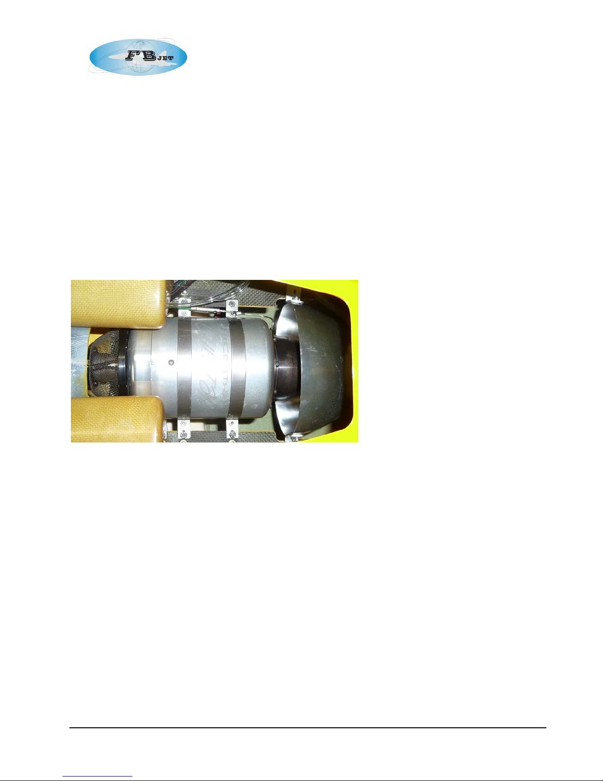
Position the Turbine on the mounting rails. Set the gap between the rear of the exhaust
cone and the mouth of the pipe to manufacturer’s specifications. This is typically around 25
mm, see photo.
When you are satisfied with the fit up, mount the turbine to the mounting rails; you can use
appropriately sized wood screws or install builder suppl ied allen bolts and blind nuts. If
using wood screws i nstall the screws into the rai ls and then remo ve, coat the thread hol es
with thin CA. This will harden the wood around the screw holes the m selves. Per m anently
reinstall the engine mounting screws. You may need to fabri cate a mounting plate adapter
depending on the wi dth of the turbi ne mo unting tabs. The installation show n used 1/16”
(1.5mm) 6061 T6 alumi num sheet stock.
Step 13: Turbine Accessory Installation
For ease of maintenance, especially for turbines that utilize separate components it is
recommended that the major turbine fuel handling components such as the pump, & solenoids,
should be mounted on a removable plywood plate. Also the ECU should be mounted for easy
access, see photos; follow the Turbine manufactures recommendations for equipment
connections.
28
Page 29
FB Jets Dolphin S
Step 14: Cockpit
The optional semi scale cockpit tub comes pre-trimmed and painted along with the preinstalled
canopy gl ass to the frame.
Check fi t of canopy frame to fuselage, adjust fitment where required, the canopy latch
should engage with li ttle effort w hen fitment is correct.
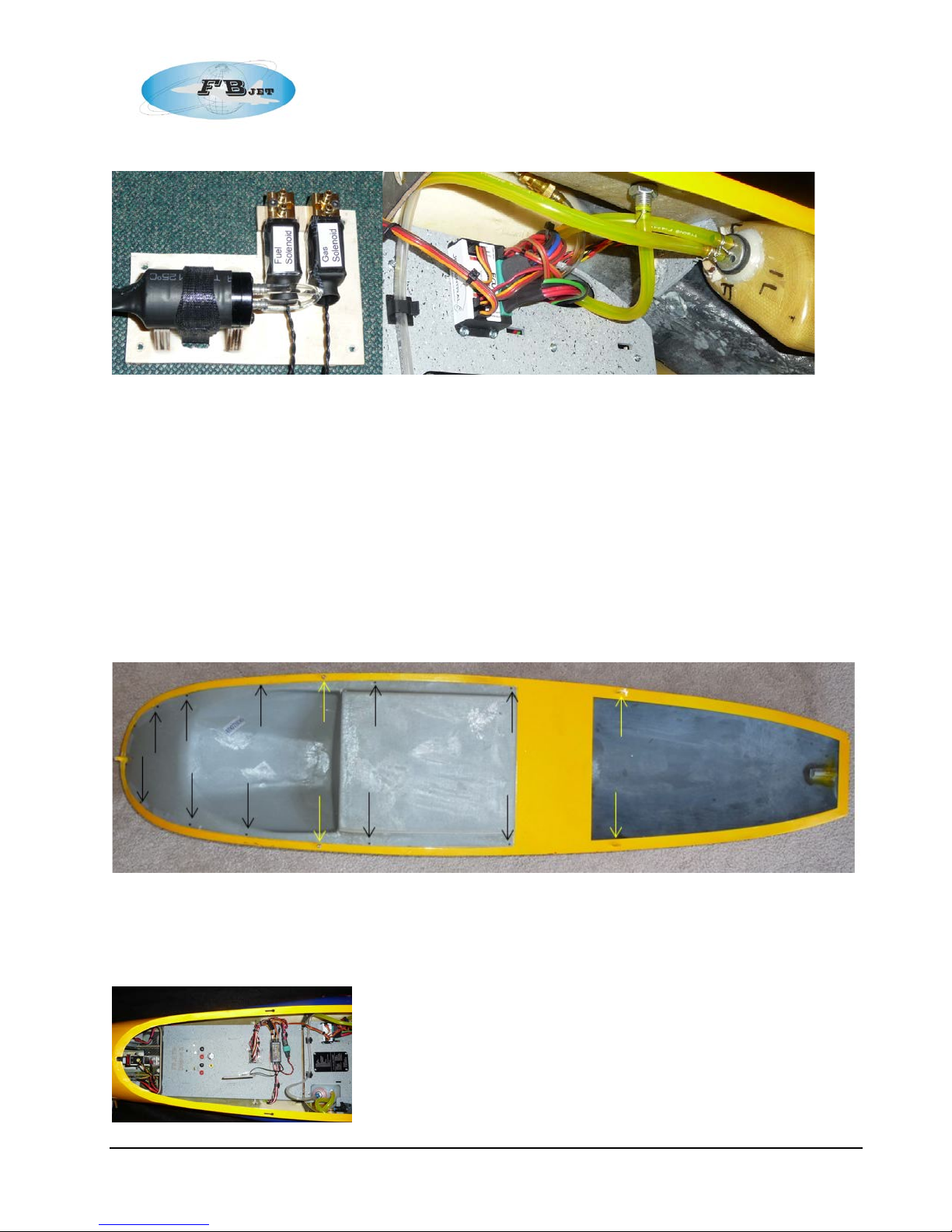
If not preinstalled, the cockpit should be screwed to the canopy frame using small screws
shown with black arrows. The Yellow Arrows in the front point to the two allen head bol ts
used to key the canopy to the fuselage slots, the y ellow arrows in the rear point to the
locating tabs that key into slots located on the fuselage. The canopy latch is preinstalled
and is located in the rear edge of the can opy.
The B olt k ey s lo ts shown in fuselage may require a bit of fitting. The front notch may also
require some fitting to make sure canopy sits flush. After fitting make sure rear latch
engages fr eely.
29
Page 30
FB Jets Dolphin S
Step 15: Radio Channel Assignment s
The prototype was set up utilizing 11 channels as follows, many radi o system and option exi st, it is
up to the builder’s discretion t o pick the equi pm ent that best fits their particular needs:
Two channels for Elevators
Two channels for Ailerons
Two channels for Flaps
One channel for Throttle
One channel for Rudder
One channel for Nose wheel steeri ng also Mix ed w ith Retract channel; enabled with Retract Down
only, low rate active with flap depl oyment
One channel for Retracts
One channel for Brakes mixed with Retract channel to be enabled with down Retract only
Step 16: C.G.
Set the Cent er of Gravi ty @ 28% of MAC which is 10.14” (257 mm) from of the leading edge of the
wing panel at the root. The C.G. should be determi ned with the UAT filled with fuel and with the
gear in the extended position. Battery positioning should be enough to achieve the correct C.G.
location without adding dead weight.
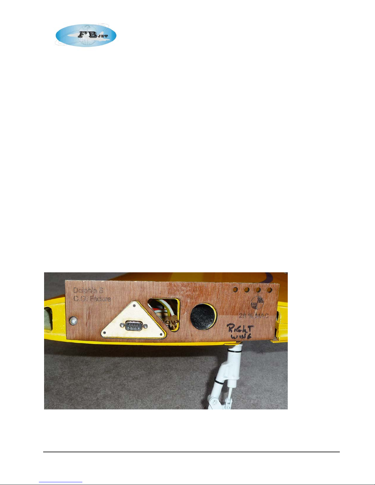
Note: To simplify the process of determining the C.G. the author created two plywood fixtures that
can be inserted between the wing panels and the fuselage, see photo. The Airframe then c an be
lifted wi th a strap on the C.G. point to al low easy adjustments.
30
Page 31
FB Jets Dolphin S
D/R Throws
High Rate
Low Rate
Elevator @ Outer Tip
0.7" (18)
0.5" (13)
Aileron @ Outer Tip
0.5" (13)
0. 3" (8)
Rudder @ Outer Tip
0.7" (18)
-
Throws
Flight
Take Off
Landing
Flap @ Root
0
0.6" (15)
1.45" (37)
Crow (Up Air) @ Tip
0
0
0.15" (3.8)
Measurements in braces ( ) are millimeters
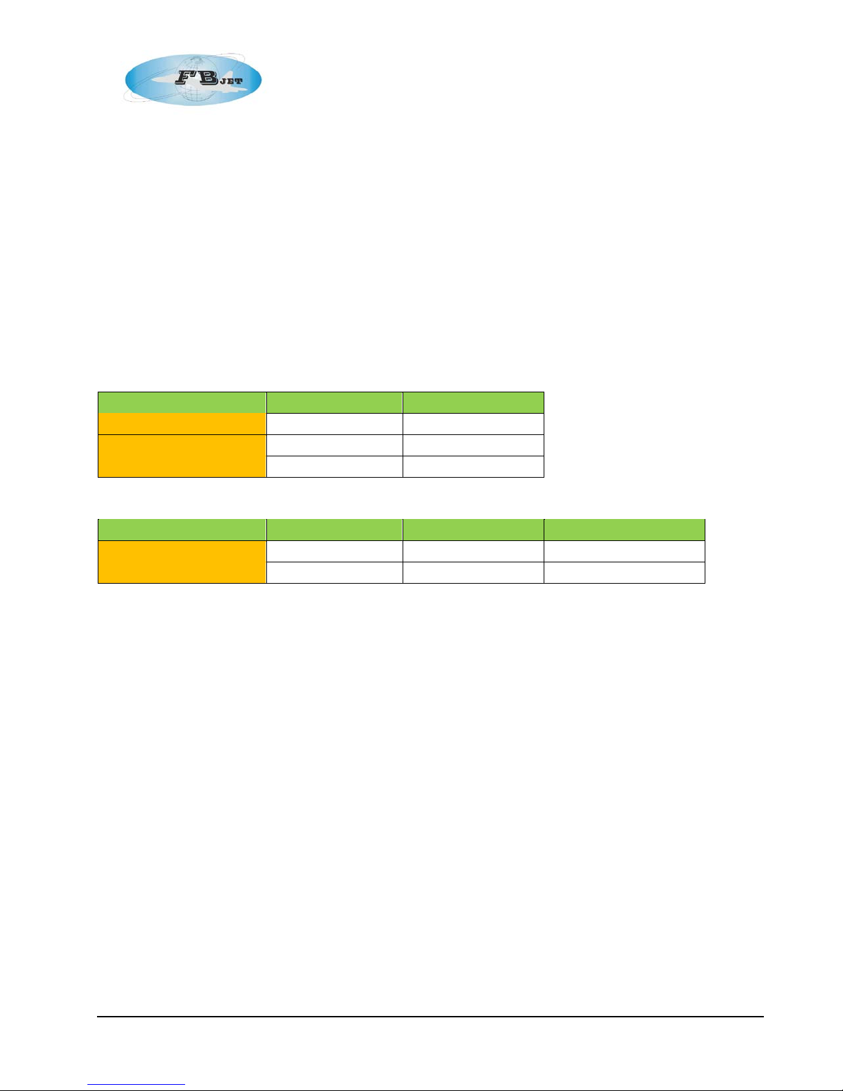
Step 17: Setting of throws
Elevator should be set values shown in table as measured from the center line of the
outboard edge (Tip).
Aileron should be set values shown in table as measured from the center line of the
outboard edge (Tip).
Flap throw set values shown in t able as measured from the center line of the inboard edge
(Root).
Rudder thr ow set values s hown in table as measured f rom the center line of the inboard
edge (Tip).
Nose Steering should be setup with dual rates to t he minimal movement to avoid over steer
during takeoff and landings, t he prototype was set wit h low rate with the deployment of
flaps.
Maintenance Tips:
When invert ing the ai rcraft, put a short piece of fuel tube wi th a plug on the drain fitting.
Cycle t he gears before ea ch flying session, checking for binding and proper operation.
Check the st ruts for play, indicating the clamping set screw needs to be ti ghtened, verify
toe in on main wheels for reliabl e tracking.
Check all hinged surfac es; i.e. pull on them before each flying session
Check for proper radi o operation, slowly cycle all surf aces with the transmitt er making sure
they are moving in the cor rect direction and proper deflection(Note: it is easy to lose a
model due to a simple mistake of selecting the wrong m odel memory in the transmitter)
Check all linkages, use keepers on the quick links
Check wing mounting nuts for tightness
Check Vertical fin clamp bol ts for tightness
Check Horizontal fin mounting bolts for tightness
Check Fuel system for leaks
Check all batteri es before each flight, setup a rout ine maint ained schedule on your
batteries making sure that they cycle properl y for capacity.
Note do not ch arge LiPo batt eries whi le install ed in the airframe, the battery boxes pro vide
easy removal of batter ies for charging.
Congratulations, you have completed construction of your Fei Bao Dolphin S
31
Page 32
Annex A Drawings
FB Jets Dolphin S
32
Page 33
Annex A Drawings
FB Jets Dolphin S
33
Page 34
Annex A Drawings
FB Jets Dolphin S
34
Page 35
Annex A Drawings
FB Jets Dolphin S
35
Page 36
Annex A Drawings
FB Jets Dolphin S
36
Page 37
Annex A Drawings
FB Jets Dolphin S
37
Page 38
Annex A Drawings
FB Jets Dolphin S
38
Page 39
28 % MAC
Annex A Drawings
FB Jets Dolphin S
39
Front
Left Side
Dolphin S
C.G. Fixture
Right Side
Front
Dolphin S
C.G. Fixture
28 % MAC
 Loading...