

FBII MX-500 Installation Instructions Manual
MX-500 Dual Technology Motion Sensor Installation Instructions
TT
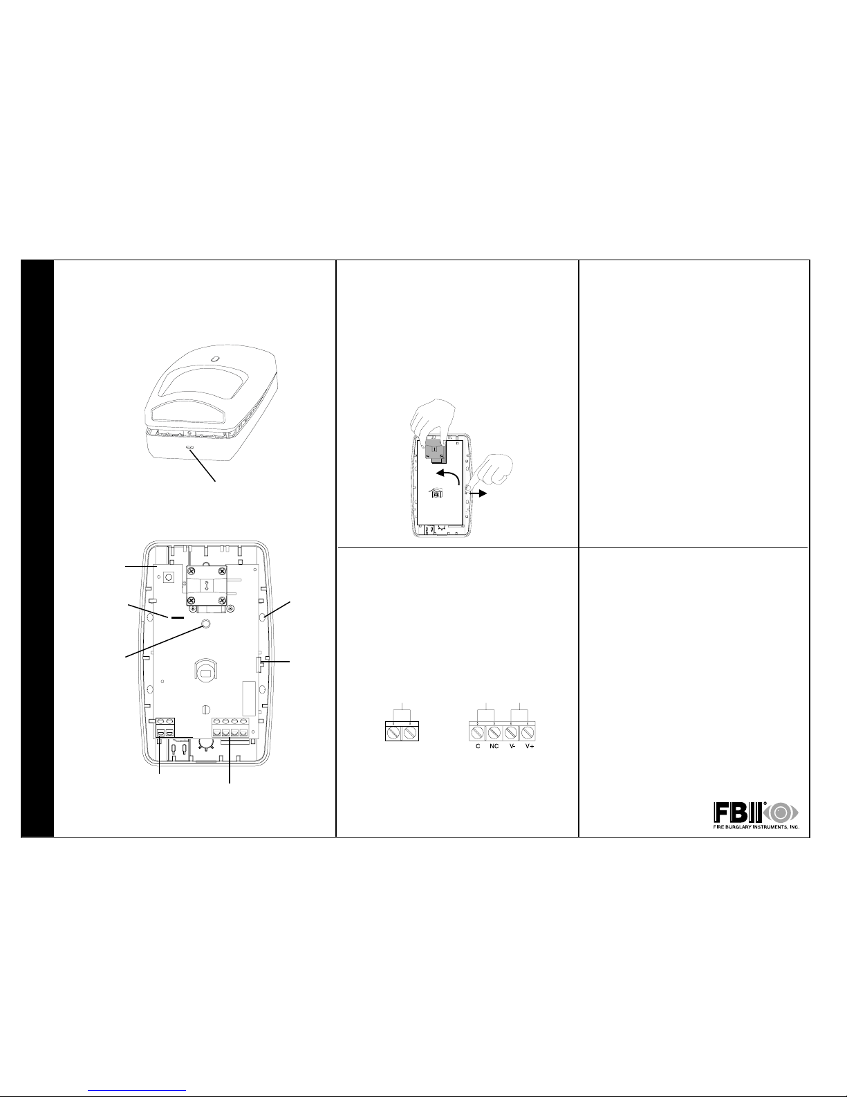
Step 1
Separate the sensor housings and remove
Printed Circuit Board (PCB).
Use a small screwdriver to unfasten the housing latch and separate the sensor housings.
Push outward on the PCB latch to lift the PCB
out of the housing.
Step 3
Wire the sensor.
Observing the proper polarity, wire the unit as
shown in the illustration below, use 1.02 to 0.64 mm
(18 to 22 AWG) wire.
Step 2
Mount the sensor.
Break out the mounting/wiring knockouts and
mount the sensor in an appropriate location.
An ideal location meets the following objectives:
• Allows a clear line-of-sight to all areas to
protect.
• Does not directly face windows.
• Avoids close proximity to moving machinery,
fluorescent lights, and heating/cooling
sources.
NOTE: maximum range is obtained at a
mounting height of 2.3 m (76).
Knockout
Housing
latch
PCB latch
FRONT HOUSING
REAR HOUSING AND PCB
Terminal Block
TB1
PCB
LED
(DS1)
LED Enable
(Cut LED enable
jumper J1 to
disable LED)*
Step 4
Walk-test the sensor.
After returning the PCB to the rear housing,
reassemble the sensor housing. Apply
power to the sensor and begin walk-test
when the red LED is off.
Walk across the detection area at the ranges
to be covered. The red LED should indicate
an alarm condition after 2 to 4 normal steps.
When there is no motion in the detection
area the LED should be off.
Terminal Block
TB2
Alarm
500 mA
30 VDC
Power
25 mA
7.5-16 VDC
(UL: 8.9-14.5 VDC)
TB1
Tamper
50 mA
24 VDC
TB2
* R
MX-500 Dual Technology Motion Sensor Supplemental Information
MICROWAVE SUPERVISION
If the microwave technology stops sending or
receiving signals, the sensor locks into an alarm
condition. The LED at the sensor, however, does
not light.
If the microwave regains its signal, the sensor
(and LED) returns to normal operation.
NOTE: The MX-500 sensor should be tested at
least once each year to ensure proper operation.
PRODUCT SPECIFICATIONS
Range:
11 m x 11 m (36' x 36')
Alarm relay:
Energized Form A
500 mA, 30 VDC
Tamper Switch:
(NC) 50 mA, 24 VDC
Power requirements:
7.5 - 16 VDC (UL: 8.9-14.5 VDC)
25 mA
AC Ripple: 3V peak-to-peak at nominal 12 VDC
Frequencies:
24.125 GHz
PIR white light immunity:
8,000 Lux
RFI immunity:
30 V/m,10 MHz - 1000 MHz
Operating temperature:
-25
o
to +65o C (-13o to +149o F)
5 - 95% relative humidity (non-condensing)
PIR fields of view:
11 m (35) Lens
44 long range edges
12 intermediate edges
6 lower edges
4 down edges
Dimensions:
11.9 cm H x 7.1 cm W x 4.2 cm D
(4.685" H x 2.795" W x 1.654" D)
Sensitivity:
2 - 4 steps within field of view
CE Notice:
Hereby, Fire Burglary Instruments, Inc. declares that this MX-500 is in compliance
with the essential requirements and other relevant provisions of Directive 1999/5/
EC.
The Declaration of Conformity for this product can be found on the Internet at:
www.fbii.com/fbiiinternational/
FCC Notice: This equipment has been tested and found to comply with the limits
for a field disturbance sensor pursuant to Part 15 of the FCC Rules. The user is
cautioned that changes or modifications not expressly approved by Fire Burglary
Instruments, Inc. could void the users authority to operate this equipment.
This equipment has been tested and found to comply with the limits for a Class B
digital device, pursuant to Part 15 of the FCC Rules. These limits are designed to
provide reasonable protection against harmful interference in a residential installation. This equipment generates, uses and can radiate radio frequency energy
and, if not installed and used in accordance with the instructions, may cause
harmful interference to radio communications. However, there is no guarantee
that interference will not occur in a particular installation. If this equipment does
cause harmful interference to radio or television reception, which can be determined by turning the equipment off and on, the user is encouraged to try to
correct the interference by one or more of the following measures:
Reorient or relocate the receiving antenna.
Increase the separation between the equipment and receiver.
Connect the equipment into an outlet on a circuit different from that to which the
receiver is connected.
Consult the dealer or an experienced radio/TV technician for help.
IC Notice: Operation is subject to the following two conditions: (1) this device may
not cause interference, and (2) this device must accept any interference, including
interference that may cause undesired operation of the device.
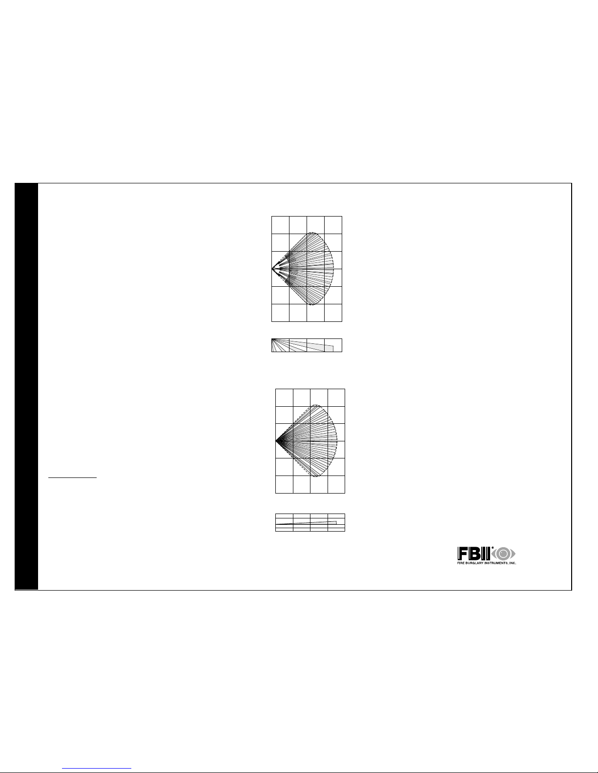
DETECTION PATTERNS
Wide Angle Lens
9m
6m
3m
0
3m
6m
9m
30’
20’
10’
0
10’
20’
30’
3m
10’
12 m
40’
9m
30’
6m
20’
2.3 m (7.5’)
0
Pet Alley Lens
30’
20’
10’
0
10’
20’
30’
9m
6m
3m
0
3m
6m
9m
3m
10’
12 m
40’
9m
30’
6m
20’
0
3m(10’)
1.2m(4’)
0
A SUBSIDIARY OF PITTWAY CORPORATION
149 Eileen Way Syosset, New York 11791
Copyright © 2000 PIT TWAY CORPORATION
PN 5-051-637-00 Rev B
LIMITED WARRANTY
Fire Burglary Instruments Inc., a Subsidiary of Pittway Corporation, and Pittway Corporation,
its divisions, subsidiaries, and affiliates (Seller) 149 Eileen Way, Syosset, New York 11791,
warrants its products to be in conformance with its own plans and specifications and to be
free from defects in materials and workmanship under normal use and service for five years
from the date stamp control on the product, or for products not having a date stamp, for
twelve months from the date of original purchase unless the installation instructions or
catalog sets forth a shorter period, in which case the shorter period shall apply. Sellers
obligation shall be limited to repairing or replacing, at its option, free of charge for materials
or labor, any part that is proved not in compliance with Sellers specifications or proves
defective in materials or workmanship under normal use and service. Seller shall have no
obligation under this Limited Warranty or otherwise if the product is altered or improperly
repaired or serviced by anyone other than Seller. For warranty service, return, transportation
prepaid, to Factory Service, 165 Eileen Way, Syosset, New York 11791.
THERE ARE NO WARRANTIES, EXPRESSED OR IMPLIED, OF MERCHANTABILITY, OR FITNESS FOR A PARTICULAR PURPOSE OR OTHERWISE, THAT EXTEND BEYOND THE DESCRIPTION ON THE FACE HEREOF. IN NO CASE SHALL SELLER BE LIABLE TO ANYONE FOR ANY
CONSEQUENTIAL OR INCIDENTAL DAMAGES FOR BREACH OF THIS OR ANY OTHER WARRANTY, EXPRESS OR IMPLIED, OR UPON ANY OTHER BASIS OF LIABILITY WHATSOEVER,
EVEN IF THE LOSS OR DAMAGE IS CAUSED BY ITS OWN NEGLIGENCE OR FAULT.
Seller does not represent that the products it sells may not be compromised or circumvented; that the products will prevent any personal injury or property loss by burglary,
robbery, fire or otherwise; or that the products will in all cases provide adequate warning
or protection. Customer understands that a properly installed and maintained alarm system may only reduce the risk of a burglary, robbery, or fire without warning, but it is not
insurance or a guarantee that such will not occur or that there will be no personal injury or
property loss as a result. CONSEQUENTLY, SELLER SHALL HAVE NO LIABILITY FOR ANY
PERSONAL INJURY, PROPERTY DAMAGE, OR OTHER LOSS BASED ON A CLAIM THE PRODUCT FAILED TO GIVE ANY WARNING. HOWEVER, IF SELLER IS HELD LIABLE, WHETHER
DIRECTLY OR INDIRECTLY, FOR ANY LOSS OR DAMAGE ARISING UNDER THIS LIMITED
WARRANTY OR OTHERWISE, REGARDLESS OF CAUSE OR ORIGIN, SELLERS MAXIMUM
LIABILITY SHALL NOT IN ANY CASE EXCEED THE PURCHASE PRICE OF THE PRODUCT,
WHICH SHALL BE THE COMPLETE AND EXCLUSIVE REMEDY AGAINST SELLER.
This warranty replaces any previous warranties and is the only warranty made by Seller on
this product. No increase or alteration, written or verbal, of the obligations of this Limited
Warranty is authorized.
 Loading...