


faytech
Industrial
Motherboard
Series
Industrial Motherboard

First Edition
June 2013
Copyright Notice
This document is copyrighted, 2013. All rights are reserved. The original
manufacturer reserves the right to make improvements to the products described
in this manual at any time without notice.
No part of this manual may be reproduced, copied, translated, or transmitted
in any form or by any means without the prior written permission of the original
manufacturer. Information provided in this manual is intended to be accurate and
reliable. However, the original manufacturer assumes no responsibility for its use,
or for any infringements upon the rights of third parties that may result from its use.
The material in this document is for product information only and is subject to
change without notice. While reasonable efforts have been made in the preparation
of this document to assure its accuracy, the original manufacturer assumes no
liabilities resulting from errors or omissions in this document, or from the use of the
information contained herein.
faytech reserves the right to make changes in the product design without notice to
its users.
Acknowledgments
All other products’ name or trademarks are properties of their respective owners.
•
•
•
•
•
AMI is a trademark of American Megatrends Inc.
Intel®, Core™ are trademarks of Intel®Corporation.
Microsoft Windows®is a registered trademark of Microsoft Corp.
ITE is a trademark of Integrated Technology Express, Inc.
IBM, PC/AT, PS/2, and VGA are trademarks of International Business
Machines Corporation.
faytech reserves the right to make changes in the product design without notice to
its users.
All other product names or trademarks are properties of their respective owners.
ii

BIOS setup
3.4
Advanced menu ............................................................................ 3-6
3.4.1
3.4.2
3.4.3
3.4.4
3.4.5
3.4.6
3.4.7
3.4.8
CPU Configuration ......................................................... 3-6
IDE Configuration ........................................................... 3-7
USB Configuration .......................................................... 3-7
APM ................................................................................ 3-7
Panel Controller (AMD®GPU only) ................................. 3-8
North Bridge LVDS Config Select (AMD®GPU only) ....... 3-8
Onboard Devices Configuration ...................................... 3-8
DIO Function ................................................................... 3-8
iii
Central Processing Unit (CPU) ..................................................... 2-6
System memory ............................................................................ 2-6
Jumpers ........................................................................................ 2-8
Connectors ................................................................................... 2-12
2.7.1
2.7.2
Rear panel connectors .................................................. 2-12
Internal connectors ........................................................ 2-13
Chapter 3:
3.1
3.2
3.3
BIOS setup program ..................................................................... 3-1
BIOS menu screen ....................................................................... 3-2
Main menu .................................................................................... 3-4
3.3.1
3.3.2
3.3.3
3.3.4
System Language [English] ........................................... 3-4
System Date [Day xx/xx/xxxx] ........................................ 3-4
System Time [xx:xx:xx] ................................................... 3-4
Security .......................................................................... 3-4
Contents
Chapter 1:
1.1
1.2
Package contents ......................................................................... 1-1
Specifications ................................................................................ 1-2
Before you proceed ....................................................................... 2-1
Motherboard layout ....................................................................... 2-2
Screw size ..................................................................................... 2-4
2.3.1
2.3.2
Component side ............................................................. 2-4
Solder side ..................................................................... 2-5
Features ........................................................................................ 1-1
Product overview
1.3
2.1
Chapter 2:
2.2
2.3
Motherboard information
2.4
2.5
2.6
2.7

Contents
3.5
Monitor menu ................................................................................. 3-9
3.5.1
3.5.2
3.5.3
3.6
3.5.4
3.6.1
3.6.2
3.6.3
3.6.4
3.7
3.8
3.6.5
CPU Temperature / MB Temperature [xxxºC/xxxºF] ....... 3-9
Chassis Fan Speed [xxxx RPM] or [N/A] ........................ 3-9
Chassis Q-Fan Control [Enabled] ................................... 3-10
CPU Voltage, 3.3V Voltage, 5V Voltage, 12V Voltage .... 3-10
Bootup NumLock State [On] ........................................... 3-10
Full Screen Logo [Disabled] ............................................ 3-11
Wait for ‘F1’ If Error [Enabled] ......................................... 3-11
Boot Option Priorities ...................................................... 3-11
Boot Override .................................................................. 3-11
Boot menu ...................................................................................... 3-10
Tools menu ..................................................................................... 3-11
Exit menu ....................................................................................... 3-12
Appendix
Notices ........................................................................................................ A-1
iv

Product overview
1.1
Package contents
Motherboard heatink/ cooler optional
Cable Kit
DVD-ROM for manual (in PDF format) and drivers
NOTE: If any of the above items are damaged or missing, contact your
distributor or sales representative immediately.
Check your industrial motherboard package for the following items.
1.2
•
•
•
•
•
•
•
•
•
•
Features
Integrated Intel®Atom™ processor N2600 / N2800 (optional)
Realtek®ALC887, Audio Amplifier EUA 2012A
Dual Ethernet LAN: Realtek®8111F x 2
SATA 3Gb/s x 2, USB2.0 x 6, COM x 4
One Single Channel DDR3 800 / 1066MHz SO-DIMM Up To 2GB
Multi Display: LVDS+HDMI, VGA+LVDS, VGA+HDMI
2 x Mini Card slots with PCIe and USB interface (1 x Full Height with SIM card
interface, 1 x Half Height, 1 x PCIe 1 x slot)
EuP/ErP Compliance
AMD®HD7410M (optional)
PCIx1 Straddle
Chapter 1: General information
1-1
Chapter 1

1.3
CPU
Memory
Chipset
I/O Chipset
LAN
Audio
Specifications
SYSTEM
Integrated Intel Atom™ processor N2600 / N2800 (optional)
®
1 x SO-DIMM, max. 2GB, DDR3 800 / 1066MHz, non-ECC, un-buffered
Memory (max. 4GB for N2800)
Single channel memory architecture
Intel®NM10
Fintek 81866D-I
2 x Realtek®8111F PCIe Gigabit LAN controllers
1 x Audio Amplifier EUA 2012A
1 x Realtek®ALC887 8-channel high definition audio CODEC
2 x Mini Card slots with PCIe and USB interface (1 x Full Height with SIM
card interface, 1 x Half Height), 1 x PCIe 1 x slot
Expansion slot
BIOS
H/W Status Monitor
Watchdog Timer
Smart Fan Control
Wake On LAN / PXE
Power States
Graphics Chipset
Graphics Multi Display
Resolution
LVDS Inverter Control
Battery
Power requirement
Power compliance
Operating
temperature
Operating humidity
Form factor
EMI
64Mb Flash ROM, UEFI AMI BIOS, PnP, DMI 2.0, Wfm 2.0, SM BIOS, ACPI
3.06
Monitors CPU/system temperature
Monitors chassis fan speed
Yes
Yes ( WOL, PXE)
S3, S4, S5
®
Monitors Vcore, 3.3V/5V/12V voltages
1~255 steps by software program
AMD HD7410M with 512M memory (optional)
LVDS+HDMI, VGA+LVDS, VGA+HDMI
VGA: Up to 1920 x 1200 @60Hz (optional)
HDMI: Up to 1920 x 1200 @60Hz
LVDS: Up to 2048 x 1536 @60Hz, 24 bit dual channel
Graphics
Environment, Power, and ME
Lithium battery
1 x DC connector on rear I/O
Compliant with Eup/ErP
14oF~131oF (-10oC~55oC)
0%~90% relative humidity, non-condensing
EPIC form factor: 4.53 in. x 6.5 in. (11.5 cm x 16.5 cm)
CE, FCC
1 x onboard 2-pin power connector
(continued on the next page)
1-2
faytech Motherboard
Voltage / PWM, 1 x DC 5V/12V for LCD backlight inverter board

Storage
USB
Display I/O
Audio I/O
LAN I/O
Serial port
PS/2 port
DIO
Fan
RTC
I/O
2 x SATA 3Gb/s ports
6 x USB 2.0 ports (2 ports at mid-board, 4 ports on rear I/O)
1 x LVDS connector, 1 x VGA connector, 1 x HDMI port
Mic-In, Line-Out, S/PDIF onboard headers
Amplifier onboard header
HDMI support audio
2 x RJ-45 ports on rear I/O
1 x 5V/12V RS232/RS485 port on rear I/O (COM1)
1 x PS/2 keyboard / mouse connector
8-bit Digital I/O interface (4-in/4-out)
1 x Chassis fan connector (4-pin)
Internal RTC
3 x RS232 onboard headers (COM2, COM3, COM4)
Back panel I/O ports 1 x HDMI port
I/O Placement
1 x COM port (RS232/485)
2 x LAN (RJ-45) port
4 x USB 2.0 ports
Internal I/O
connectors
1 x Lockable DC power port (12V)
1 x VGA pin header
1 x 12V DC power connector (2-pin)
2 x SATA 3Gb/s connectors
1 x 4-pin SATA power connector
1 x PS/2 keyboard/mouse connector (6-pin)
3 x RS232 COM connectors
1 x LVDS connector
1 x USB 2.0 header supports additional 2 USB 2.0 ports
1 x 5-pin LCD power connector
1 x Full Height Mini Card slot
1 x SIM card connector
1 x Half Height Mini Card slot
1 x 4-pin audio amplifier connector
1 x S/PDIF output pin header
1 x DIO connector
1 x PCIeX1 Straddle
1 x Line-Out / Mic-In audio pin header (AAFP)
(continued on the next page)
Chapter 1: General information
1-3

Others
Supported OS
Windows®XP 32-bit
Windows®7 32-bit
Windows®8 32-bit
Linux Fedora
Windows®XP 64-bit (only with AMD graphics)
Windows®7 64-bit (only with AMD graphics)
Windows®8 64-bit (only with AMD graphics)
Accessories
1 x SATA 3Gb/s cable
1 x SATA power cable
1 x Support DVD (Drivers, Manual)
NOTE: Specifications are subject to change without notice.
1-4
faytech Motherboard

Chapter 2
2.1
Motherboard information
Before you proceed
Take note of the following precautions before you install motherboard components
or change any motherboard settings.
CAUTION!
•
•
Unplug the power cord from the wall socket before touching any
component.
Before handling components, use a grounded wrist strap or touch a safely
grounded object or a metal object, such as the power supply case, to avoid
damaging them due to static electricity.
Hold components by the edges to avoid touching the ICs on them.
Whenever you uninstall any component, place it on a grounded antistatic
pad or in the bag that came with the component.
Before you install or remove any component, ensure that the power supply
is switched off or the power cord is detached from the power supply. Failure
to do so may cause severe damage to the motherboard, peripherals, or
components.
•
•
•
Chapter 2: Motherboard information
2-1

11
12
13
14
9
SATA_PWR1
DDR3 DIMM_A1
DC_PWR
EATX_PWR1
CHA_FAN1
Place this side towards
the rear of the chassis
191817 16
COM3
COM4
J1
15
2-2
faytech Motherboard
2.2
Motherboard layout
NOTE: Place five screws into the holes indicated by circles to secure the
motherboard to the chassis.
CAUTION! Do not overtighten the screws! Doing so can damage the
motherboard.
1
2
PCIeX1
3
11.5cm(4.53in)
AAFP1
4
5
AMP_CON1
SPEAKER
SPDIF_OUT1
HDMI1
ALC
887
MINI_CARD1
SPI1
SIM1
ICS
9VRS4339AL
SATA3G_2
SATA3G_1
ISD72
D9MGG
6
7
AMD
®
HD7410M
LAN1
RTL
8111F
AMD
®
GPU (optional)
PEX8605
ISD72
D9MGG
MINI_CARD2
PLX
LAN2
USB2
RTL
8111F
Intel
®
NM10
R560
010S LVDS1
16.5cm(6.5i
n)
DIO1
COM2
COM1
J2
N2600
BATTERY
LVDS_VDD_SEL1CLRTC
1
242322
21
20
Super
I/O
Intel
®
F_PANEL1
INV1
KBMS1
LCD_POWER_SEL1L_B
RIGHTNESS1
25
USB3
USB1
26
VGA
8
10

Connectors/Jumpers/Slots
1. Digital audio connector (4-1 pin SPDIF_OUT1)
2. Line-Out / Mic-In audio connector (10-1 pin AAFP1)
3. SPI programming connector (8-pin SPI1)
4. Audio amplifier connector (4-pin AMP_CON1)
5. Serial ATA 3Gb/s connectors (7-pin SATA3G_1/2)
6. Internal speaker connector (4-pin SPEAKER)
7. LVDS connector (30-pin LVDS1)
8. VGA connector (16-pin VGA)
9. LCD inverter power setting jumper (3-pin LCD_POWER_SEL1)
10. LVDS backlight brightness control jumper (3-pin L_BRIGHTNESS1)
11. Backlight inverter power connector (5-pin INV1)
12. System panel connector (10-1 pin F_PANEL1)
13. Digital I/O connector (10-pin DIO1)
14. Serial port connectors (9-pin COM2/3/4)
15. Chassis fan connector (4-pin CHA_FAN1)
16. Clear RTC RAM (3-pin CLRTC1)
17. LVDS panel VDD setting jumper (3-pin LVDS_VDD_SEL1)
18. PCIeX1 Straddle
19. EATX power connector (2-pin EATX_PWR1) 12V, DC-IN (1: + 2: GND)
20. Lockable DC power port (DC_PWR) 12V, DC-IN
21. SATA power connector (4-pin SATA_PWR1)
22. COM1 Ring and voltage selection (6-pin J1)
23. Battery connector (2-pin BATTERY)
24. AT Mode selection (2-pin J2)
25. PS/2 keyboard/mouse connector (6-pin KBMS1)
26. USB 2.0 connector (10-pin USB1)
Page
2-13
2-13
2-18
2-20
2-17
2-15
2-21
2-20
2-11
2-10
2-19
2-16
2-22
2-14
2-15
2-8
2-10
2-6
2-14
2-12
2-17
2-9
2-21
2-9
2-19
2-18
NOTES:
•
•
If your motherboard has an onboard AMD®GPU, you should install the
display driver.
If your motherboard does not have an onboard AMD®GPU, you should
install the VGA driver.
Chapter 2: Motherboard information
2-3

2.3
2.3.1
Screw size
Component side
2-4
faytech Motherboard

2.3.2
Solder side
Chapter 2: Motherboard information
2-5

2.4
Central Processing Unit (CPU)
The motherboard comes with an integrated Intel®Atom™ processor N2600 /
N2800 (optional).
Integrated Intel
®
Atom™ processor
faytech Industrial Motherboard Series Integrated Intel®Atom™ processor
2.5
System memory
This motherboard comes with one Double Data Rate 3 (DDR3) Small Outline Dual
Inline Memory Modules (SO-DIMM) socket. The figure illustrates the location of the
DDR3 DIMM socket:
DIMM_A1
faytech Industrial Motherboard Series DDR3 DIMM socket
faytech Industrial Motherboard Series
PCIxe1 Straddle
3
2-6
faytech Motherboard
faytech Industrial Motherboard Series Integrated Intel®Atom™ processor

To install a DIMM
To remove a DIMM
3
Chapter 2: Motherboard information
2-7
2.6
1.
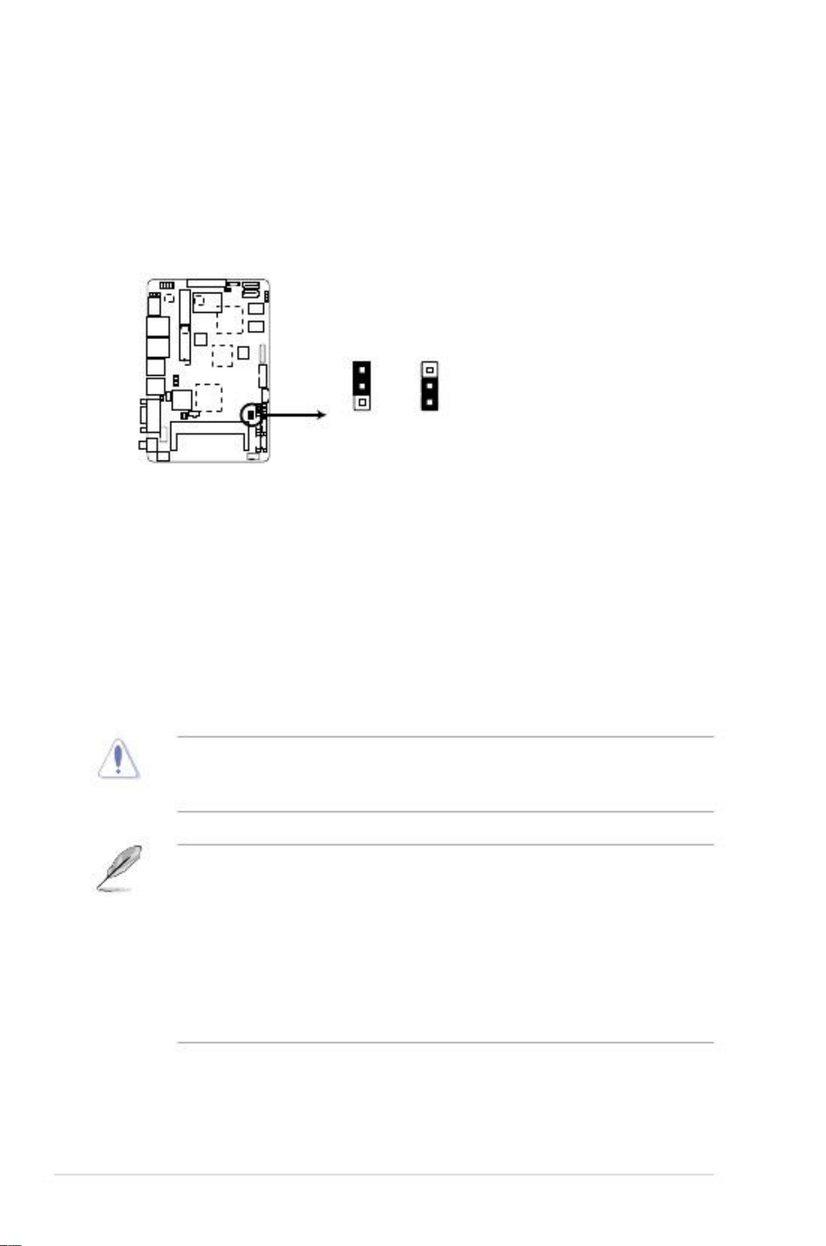
This jumper allows you to clear the Real Time Clock (RTC) RAM in
CMOS. You can clear the CMOS memory of date, time, and system setup
parameters by erasing the CMOS RTC RAM data. The onboard button
cell battery powers the RAM data in CMOS, which include system setup
information such as system passwords.
Clear RTC RAM (3-pin CLRTC1)
Jumpers
CLRTC1
2
1
2
Normal
(Default)
Clear
faytech Industrial Motherboard Series Clear CMOS RAM
To erase the RTC RAM:
1.
2.
3.
4.
Turn OFF the computer and unplug the power cord.
Move the jumper cap from pins 1-2 (default) to pins 2-3. Keep the cap on
pins 2-3 for about 5~10 seconds, then move the cap back to pins 1-2.
Plug the power cord and turn ON the computer.
Hold down the <Del> key during the boot process and enter BIOS setup
to reenter data.
CAUTION! Except when clearing the RTC RAM, never remove the cap on
CLRTC jumper default position. Removing the cap will cause system boot
failure!
NOTES:
•
If the steps above do not help, remove the onboard battery and move the
jumper again to clear the CMOS RTC RAM data. After clearing the CMOS,
reinstall the battery.
You do not need to clear the RTC when the system hangs due to
overclocking. For system failure due to overclocking, use the CPU
Parameter Recall (C.P.R) feature. Shut down and reboot the system so the
BIOS can automatically reset parameter settings to default values.
•
3
2-8
faytech Motherboard
2.
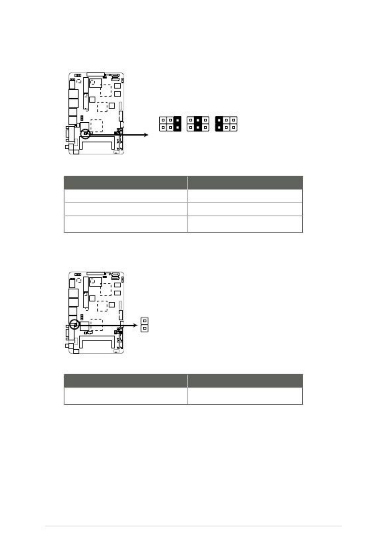
COM1 Ring and voltage selection (6-pin J1)
J1
12345
6
+12V
+5V
Ring
(Default)
faytech Industrial Motherboard Series COM1 Ring and voltage selection
Pins
1-2
3-4
5-6
+12V
+5V
Ring (Default)
3.
AT Mode selection (2-pin J2)
J2
PIN1
AT MODE
faytech Industrial Motherboard Series AT Mode selection
Pins
1-2
AT Mode
Chapter 2: Motherboard information
2-9

4.
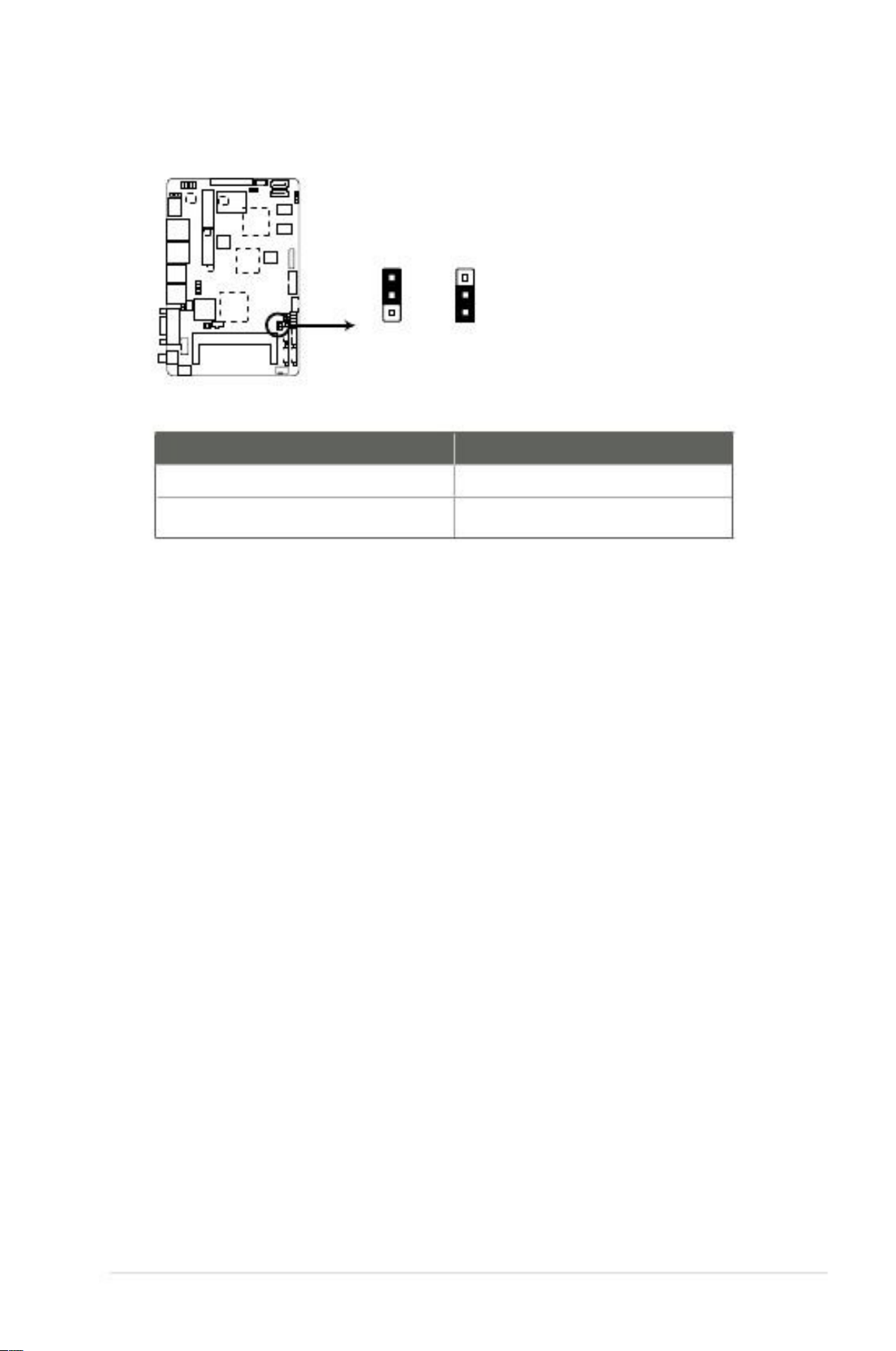
LVDS backlight brightness control jumper (3-pin L_BRIGHTNESS1)
L_BRIGHTNESS1
2
1
DC MODE
(Default)
PWM MODE
faytech Industrial Motherboard Series LVDS backlight brightness control jumper
Pins
1-2
2-3
DC Mode (Default)
PWM Mode
5.
LVDS panel VDD setting jumper (3-pin LVDS_VDD_SEL1)
LVDS_VDD_SEL1
2
1
2
+3V
+5V
(Default)
faytech Industrial Motherboard Series LVDS panel VDD setting jumper
Pins
1-2
2-3
+3V
+5V (Default)
3
2-10
faytech Motherboard
6.
LCD inverter power setting jumper (3-pin LCD_POWER_SEL1)
LCD_POWER_SEL1
2
1
2
+12V
(Default)
+5V
faytech Industrial Motherboard Series LCD inverter power setting jumper
Pins
1-2
2-3
+12V (Default)
+5V
Chapter 2: Motherboard information
3
2-11
2.7
2.7.1
Connectors
Rear panel connectors
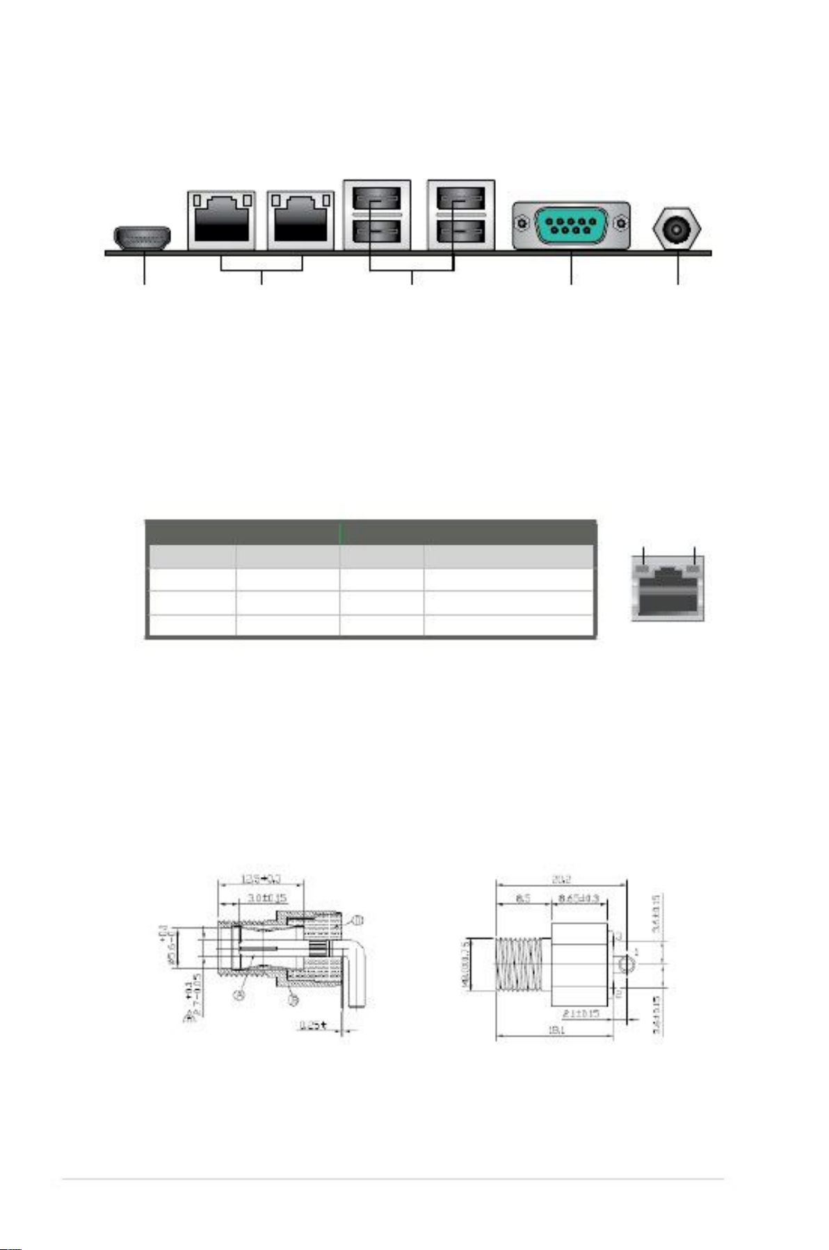
1
1.
2.
234
5
LAN (RJ-45) ports. These ports allow Gigabit connection to a Local Area
Network (LAN) through a network hub. Refer to the table below for the LAN
port LED indications.
LAN port LED indications
ACT/LINK LED StatusDescription
OFFNo link
ORANGE Linked
BLINKING Data activity
SPEED LED StatusDescription
OFF10 Mbps connection
ORANGE 100 Mbps connection
GREEN1 Gbps connection
Activity
Link LED
Speed
LED
HDMI port. This port is for a High-Definition Multimedia Interface (HDMI)
connector, and is HDCP compliant allowing playback of HD DVD, Blu-Ray,
and other protected content.
LAN port
3.
4.
5.
COM port. This 9-pin COM1 port is for pointing devices or other serial
devices.
USB 2.0 ports. These two 12-pin Universal Serial Bus (USB) ports are
available for connecting USB 2.0/1.1 devices.
Lockable DC power port (+12V). This port connects to a DC power adapter.
To select the correct power adapter, refer to the inner and outer dimensions
of this power port.
2-12
faytech Motherboard
2.7.2
1.
Internal connectors
This connector is for Line-Out / Mic-In audio connection.
AAFP1
LINE1-JD
GNDNCMIC1-JD
PIN 1
Line-Out / Mic-In audio connector (10-1 pin AAFP1)
faytech Industrial Motherboard Series Line-Out / Mic-In audio connector
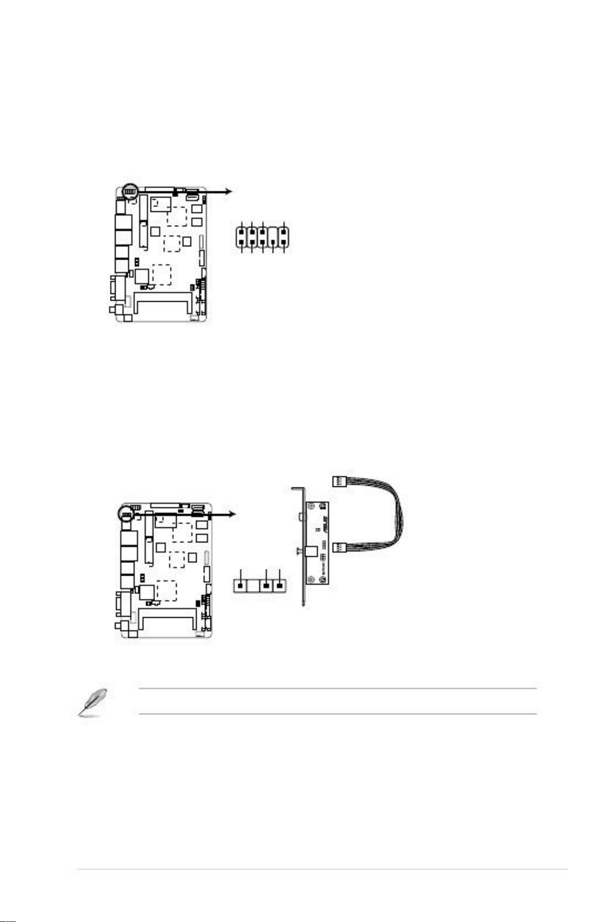
2.
Digital audio connector (4-1 pin SPDIF_OUT1)
This connector is for an additional Sony/Philips Digital Interface (S/PDIF)
port. Connect the S/PDIF Out module cable to this connector, then install the
module to a slot opening at the back of the system chassis.
PIN 1
SPDIF_OUT1
faytech Industrial Motherboard Series Digital audio connector
NOTE: The S/PDIF module is purchased separately.
Chapter 2: Motherboard information
A_SPDIF_OUTGN
D
+5V
A_MIC1_LA_MIC1_RLINE-RA
_JD_FRONTLINE-L
2-13
3.
This connector is for EATX power supply plug. The power supply plug
Is designed to fit this connector in only one orientation. Find the proper
Orientation and push down firmly until the connector completely fit.
EATX power connector (2-pin EATX_PWR1)
EATX_PWR1
+ -
faytech Industrial Motherboard Series EATX power connector
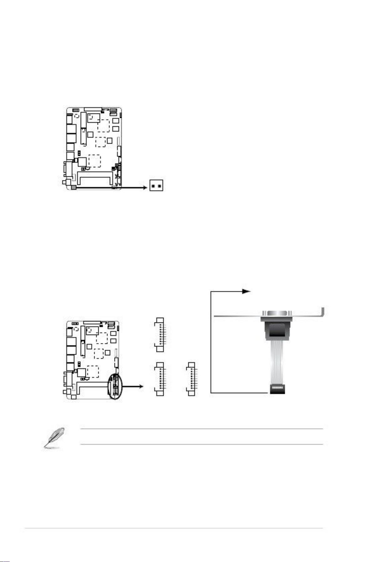
4.
Serial port connectors [WtoB CON 9P, 1.25mm, S/T, SMT / ACES / 5027300971-001] (9-pin COM2/3/4)
These connectors are for serial (COM) ports. Connect the serial port module
cable to this connector, then install the module to a slot opening at the back
of the system chassis.
COM4
GND
RI
DTR
CTS
TXD
RTS
RXD
DSR
DCD
PIN 1
COM3
GND
RI
DTR
CTS
TXD
RTS
RXD
DSR
DCD
PIN 1
COM2
GND
RI
DTR
CTS
TXD
RTS
RXD
DSR
DCD
PIN 1
faytech Industrial Motherboard Series Serial port connectors
NOTE: The COM module is purchased separately.
2-14
faytech Motherboard

5.
Connect the fan cable to the fan connector on the motherboard, ensuring that
the black wire of the cable matches the ground pin of the connector.
Chassis fan connector (4-pin CHA_FAN1)
CHA_FAN1
PWMSENSEVCCGND
faytech Industrial Motherboard Series Chassis fan connector
CAUTION: Do not forget to connect the fan cable to the fan connector.
Insufficient air flow inside the system may damage the motherboard
components. This is not a jumper! Do not place jumper caps on the fan
connector!
6.
The 4-pin connector is for the chassis-mounted system warning speaker. The
speaker allows you to hear system beeps and warnings.
SPEAKER
PIN 1
Internal speaker connector (4-pin SPEAKER)
+5V
GND
GND
SPKO
faytech Industrial Motherboard Series Internal speaker connector
Chapter 2: Motherboard information
2-15
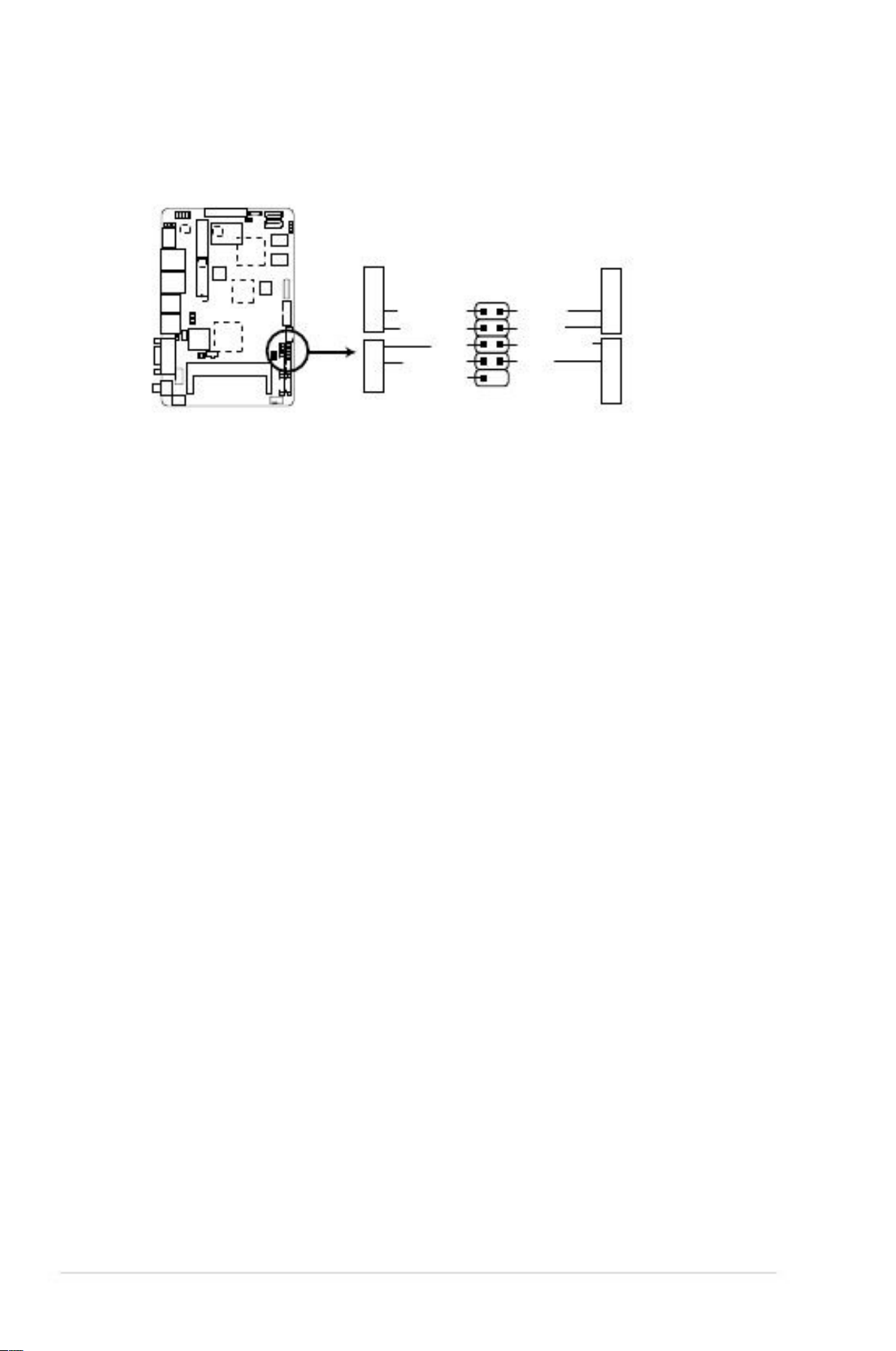
7.
This connector supports several chassis-mounted functions.
System panel connector (10-1 pin F_PANEL1)
F_PANEL1
+HD_LED
PIN 1
HD_LED+
HD_LED-
GND
HWRST#
(NC)
faytech Industrial Motherboard Series System panel connector
•
This 2-pin connector is for the system power LED. Connect the chassis
power LED cable to this connector. The system power LED lights up when
you turn on the system power, and blinks when the system is in sleep mode.
Hard disk drive activity LED (2-pin +HD_LED)
This 2-pin connector is for the HDD Activity LED. Connect the HDD Activity
LED cable to this connector. The IDE LED lights up or flashes when data is
read from or written to the HDD.
ATX power button/soft-off button (2-pin PWR BTN)
This 2-pin connector is for the system power button.
Reset button (2-pin RESET)
System power LED (2-pin PWR LED)
•
•
•
This 2-pin connector is for the chassis-mounted reset button for system
reboot without turning off the system power.
RESET
PLED+
PLEDPANSWH#
GND
PWR BTN PWR
LED
2-16
faytech Motherboard
8.
These connectors connect to Serial ATA 3Gb/s hard disk drives and optical
drives via Serial ATA 3Gb/s signal cables.
SATA3G_2
Serial ATA 3Gb/s connectors (7-pin SATA3G_1/2])
faytech Industrial Motherboard Series SATA 3.0Gb/s connectors
NOTES:
•
•
•
These connectors are set to [IDE] by default. In IDE mode, you can connect
Serial ATA boot/data hard disk drives to these connectors.
You must install Windows® XP Service Pack 3 or later version before using
Serial ATA hard disk drives.
When using hot-plug and NCQ, set the Configure SATA as item in the
BIOS to [AHCI]. See section 3.4.2 IDE Configuration for details.
9.
This connector is for the SATA power cable. The power cable plug is
Designed to fit this connector inonly one orientation. Find the proper
Orientation and push down firmly until the connector completely fit.
SATA power connector (4-pin SATA_PWR1)
SATA_PWR1
+5V
GND
GND
+12V
faytech Industrial Motherboard Series SATA power connector
Chapter 2: Motherboard information
GNDRSATA_RXP1RSATA_RXN1GNDRSATA_TXN
1RSATA_TXP1GND
GNDRSATA_TXP2RSATA_TXN2GNDRSATA_RXN
2RSATA_RXP2GND
SATA3G_1
2-17

10. USB 2.0 connector (10-pin USB1)
This connector is for USB 2.0 ports. Connect the USB module cable to
this connector, then install the module to a slot opening at the back of the
system chassis. This USB connector complies with USB 2.0 specification that
supports up to 480 Mbps connection speed.
USB1
PIN 1
+5V
USB4-_R
USB4+_R
GND
GND
GND
GND
USB5+_R
USB5-_R
+5V
faytech Industrial Motherboard Series USB 2.0 connector
CAUTION! Never connect a 1394 cable to the USB connector. Doing so will
damage the motherboard!
NOTE: The USB module cable is purchased separately.
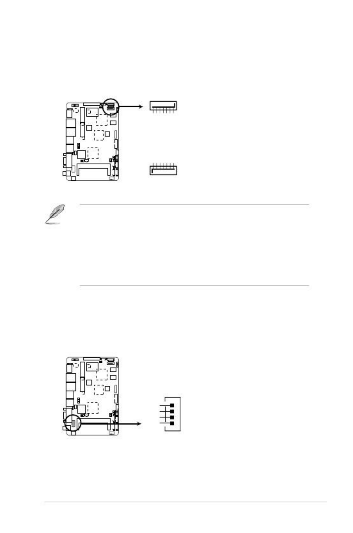
11.
Use this connector to flash BIOS SPI ROM.
GNDSPI_CLKSPI_MO
SI(NC)
SPI programming connector (8-pin SPI1)
SPI1
+V3.3SPISPI_CS#SPI_
MISO(NC)
PIN 1
faytech Industrial Motherboard Series SPI programming connector
2-18
faytech Motherboard

12. PS/2 keyboard/mouse connector (6-pin KBMS1)
This connector is for an IBM PS/2-compatible keyboard or mouse.
KBMS1
MS_DATA
GND
KB_DATA
PIN 1
MS_CLK
+5V
KB_CLK
faytech Industrial Motherboard Series PS/2 keyboard/mouse connector
13
Backlight inverter power connector [WAFER HD 5P S/T 2.0mm WHITE /
PINREX / 721-81-05TW00] (5-pin INV1)
Connect the backlight inverter power cable to this connector.
INV1
+VCC_LVDS1_BKLT
L_BRIGHTNESS1
GND
GND
BKLT_EN
faytech Industrial Motherboard Series Backlight inverter power connector
NOTE: The backlight inverter power cable is purchased separately.
Chapter 2: Motherboard information
2-19

14. VGA connector [BOX HEADER 2X8P S/T 2.0mm SMT // PINREX / 52M-90-
16GBE0] (16-pin VGA)
This 16-pin connector is for a VGA monitor or other VGA-compatible devices.
VGA
PIN 1
DAC_R
DAC_G
DAC_B
NC
GND
NC
GND
GND
+5V
GND
NC
RDDCA_DATA_R
R_HSYNC
R_VSYNC
RDDCA_CLK_R
GND
faytech Industrial Motherboard Series VGA connector
15. Audio amplifier connector [WtoB CON4P, 1.25mm, S/T, SMT // ACES / A
85025-04701] (4-pin AMP_CON1)
This connector is for an external audio amplifier.
AMP_CON1
LOUTPLOUTNROUTNROU
TP
PIN 1
faytech Industrial Motherboard Series Speaker out connector
2-20
faytech Motherboard

16. LVDS connector [WtoB CON 2P, 1.25mm, R/A, SMT // ACES / 8520402001] (30-pin LVDS1)
This connector is for an LCD monitor that supports Low-voltage differential
signaling (LVDS) interface.
LVDS1
PIN 1
BKLT_EN
LVDS_DN0
LVDS_DP0
+VDD_LVDS1
LVDS_DN1
LVDS_DP1
+VDD_LVDS1
LVDS_DN2
LVDS_DP2
LDDC_DATA
LVDS_DN3
LVDS_DP3
+VDD_LVDS1
LVDS_CLKN
L_BRIGHTNESS1
LVDSB_L0N_GPU
LVDSB_L0P_GPU
GND
LVDSB_L1N_GPU
LVDSB_L1P_GPU
GND
LVDSB_L2N_GPU
LVDSB_L2P_GPU
LDDC_CLK
LVDSB_L3N_GPU
LVDSB_L3P_GPU
GND
LVDSB_LCLKN_GPU
faytech Industrial Motherboard Series LVDS connector
17. Battery connector (2-pin BATTERY)
This connector is for the lithium CMOS battery.
BATTERY
GND
BATT1
PIN 1
faytech Industrial Motherboard Series Battery connector
Chapter 2: Motherboard information
2-21

18. Digital I/O connector (10-pin DIO1)
This connector includes 8 I/O lines. All of the Digital I/O lines are
programmable and each I/O pin can be individually programmed to support
various devices.
DIO1
PIN 1
DIO_P#1 (GPIO80)
DIO_P#3 (GPIO82)
DIO_P#5 (GPIO84)
DIO_P#7 (GPIO86)
+5V
DIO_P#2 (GPIO81)
DIO_P#4 (GPIO83)
DIO_P#6 (GPIO85)
DIO_P#8 (GPIO87)
GND
faytech Industrial Motherboard Series Digital I/O connector
NOTE: To configure the I/O pins in BIOS, go to the Advanced tab > DIO
Function > GPIO 1~8. See section 3.4.6 DIO Function for details.
2-22
faytech Motherboard

Chapter 3
BIOS setup
3.1
BIOS setup program
Use the BIOS Setup program to update the BIOS or configure its parameters. The
BIOS screens include navigation keys and brief online help to guide you in using
the BIOS Setup program.
Entering BIOS Setup at startup
•
To enter BIOS Setup at startup:
Press <Delete> during the Power-On Self Test (POST). If you do not press
<Delete>, POST continues with its routines.
Entering BIOS Setup after POST
•
•
•
To enter BIOS Setup after POST:
Press <Ctrl>+<Alt>+<Del> simultaneously.
Press the reset button on the system chassis.
Press the power button to turn the system off then back on. Do this option only
If you failed to enter BIOS Setup using the first two options.
NOTE: Using the power button, reset button, or the <Ctrl>+<Alt>+<Del> keys
to force reset from a running operating system can cause damage to your data
or system. We recommend to always shut down the system properly from the
operating system.
IMPORTANT:
•
The default BIOS settings for this motherboard apply for most conditions
to ensure optimum performance. If the system becomes unstable after
changing any BIOS settings, load the default settings to ensure system
compatibility and stability. Select the Load Optimized Defaults item under
the Exit menu. See section 3.8 Exit Menu for details.
Ensure that a USB mouse is connected to your motherboard if you want to
use the mouse to control the BIOS setup program.
The BIOS setup screens shown in this section are for reference purposes
only, and may not exactly match what you see on your screen.
If the system fails to boot after changing any BIOS setting, try to clear the
CMOS and reset the motherboard to the default value. See section 2.6
Jumpers for information on how to erase the RTC RAM.
3-1
•
•
•
Chapter 3: BIOS setup
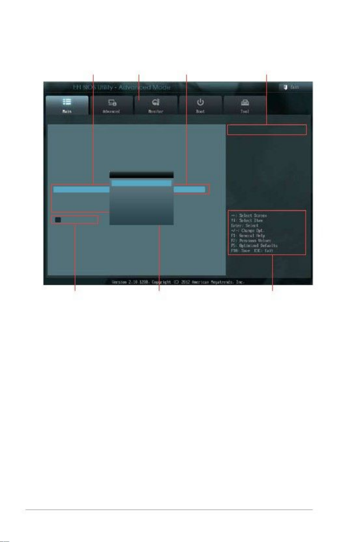
3.2
BIOS menu screen
Menu items
Menu bar
Configuration fields
General help
BIOS Information
BIOS Version
Build Date
CPU Information
Intel(R) Atom(TM) CPU 600 @ 1.60GHz
Speed
Memory Information
Total Memory
System Language
System Date
System Time
Access Level
> Security
System Language
English
Français
Español
Deutsch
Русский
0202 x64
11/30/2012
Choose the system default language
1600 MHz
2048 MB
English
[Saturday 01/03/2009]
[16:46:15]
Administrator
Submenu items
Pop-up window
Navigation keys
Menu bar
The menu bar on top of the screen has the following main items:
Main
Advanced
Monitor
Boot
Tool
Exit
For changing the basic system configuration.
For changing the advanced system settings.
For displaying the system temperature, power status, and
changing the fan settings
For changing the system boot configuration.
For configuring options for special functions.
For selecting the exit options and loading default settings.
3-2
faytech Motherboard

Chapter 3: BIOS setup
3-3
Menu items
Thehighlighted item on the menu bar displays the specific items for that menu. For
example, selecting Main shows the Main menu items.
The other items (Ai Tweaker, Advanced, Monitor, Boot, Tool, and Exit) on the menu
bar have their respective menu items.
Back button
This button appears when entering a submenu. Press <Esc> or use the USB
mouse to click this button to return to the previous menu screen.
Submenu items
A greater than sign (>) before each item on any menu screen means that the item
has a submenu. To display the submenu, select the item and press <Enter>.
Pop-up window
Select a menu item and press <Enter> to display a pop-up window with the
Configuration options for that item.
Navigation keys
At the bottom right corner of the menu screen are the navigation keys for the BIOS
setup program. Use the navigation keys to select items in the menu and change
the settings.
General help
At the top right corner of the menu screen is a brief description of the selected
item.
Configuration fields
These fields show the values for the menu items. If an item is user-configurable,
you can change the value of thefield opposite the item. You cannot select an item
that is not user-configurable.
A configurable field is highlighted when selected. To change the value of a field,
select it and press <Enter> to display a list of options.
Chapter 3: BIOS setup
3-3
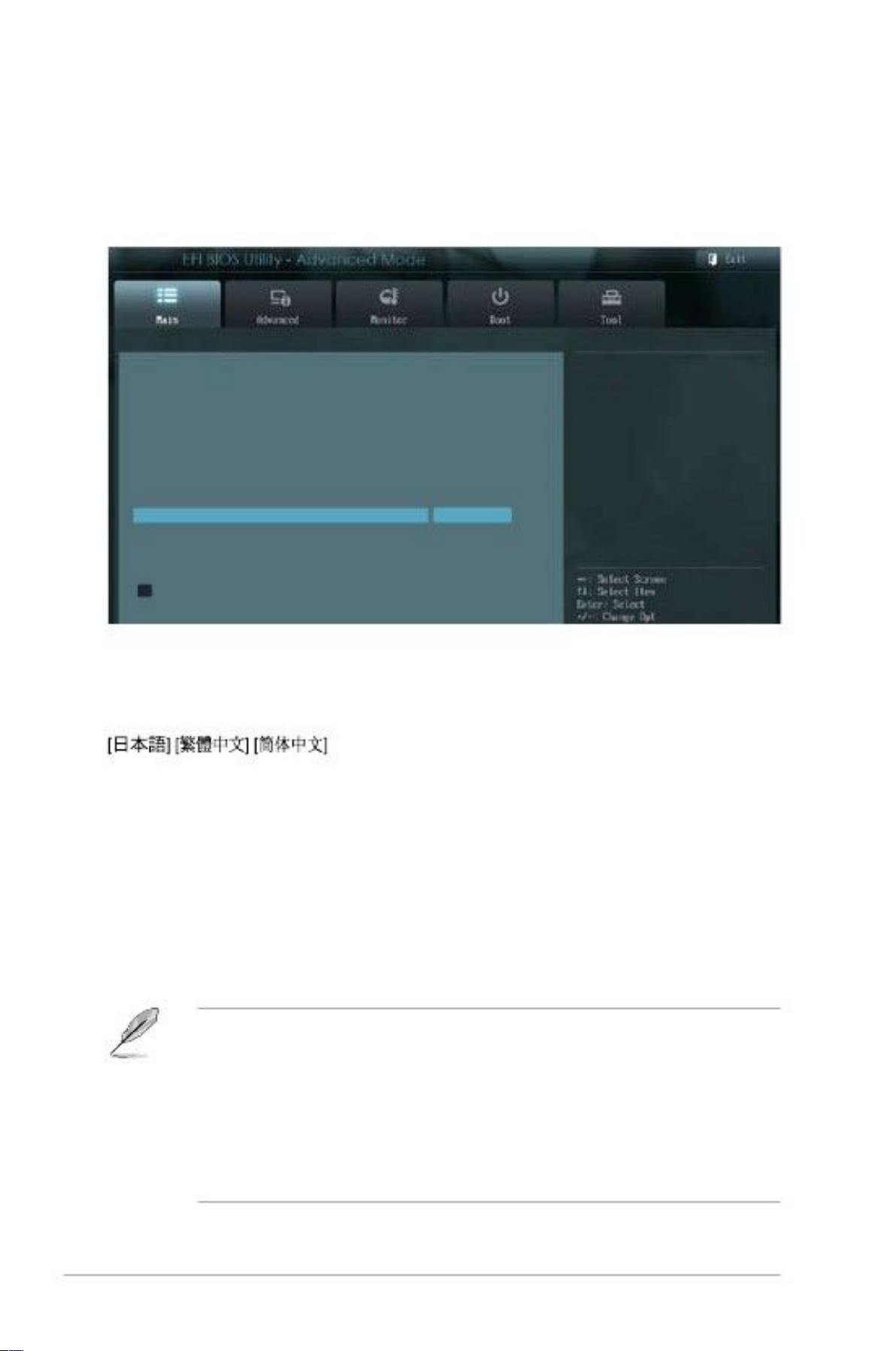
3.3
Main menu
The Main menu screen appears when you enter the Advanced Mode of the BIOS
Setup program. The Main menu provides you an overview of the basic system
information, and allows you to set the system date, time, language, and security
settings.
BIOS Information
BIOS Version
Build Date
CPU Information
Intel(R) Atom(TM) CPU 600 @ 1.60GHz
Speed
Memory Information
Total Memory
System Language
System Date
System Time
Access Level
> Security
0202 x64
11/30/2012
Choose the system default language
1600 MHz
2048 MB
English
[Saturday 01/03/2009]
[16:46:15]
Administrator
3.3.1
Allows you to choose the BIOS language version from the options.
Configuration options: [English] [Français] [Español] [Deutsch] [Русский]
System Language [English]
3.3.2
3.3.3
3.3.4
Allows you to set the system date.
Allows you to set the system time.
System Date [Day xx/xx/xxxx]
System Time [xx:xx:xx]
Security
The Security menu items allow you to change the system security settings.
NOTES:
•
If you have forgotten your BIOS password, erase the CMOS Real Time
Clock (RTC) RAM to clear the BIOS password. See section 2.6 Jumpers
for information on how to erase the RTC RAM.
The Administrator or User Password items on top of the screen show
the default Not Installed. After you set a password, these items show
Installed.
•
3-4
faytech Motherboard

C
Administrator Password
If you have set an administrator password, we recommend that you enter the
administrator password for accessing the system. Otherwise, you might be able to
see or change only selected fields in the BIOS setup program.
To set an administrator password:
1.
2.
3.1.2.
3.
4.
Select the Administrator Password item and press <Enter>.
From the Create New Password box, key in a password, then press
<Enter>.
Confirm the password when prompted.
Select the Administrator Password item and press <Enter>.
To change an administrator password:
From the Create New Password box, key in a new password, then press
<Enter>.
Confirm thepassword when prompted.
From the Enter Current Password box, key in the current password, then
press <Enter>.
To clear the administrator password, follow the same steps as in changing an
Administrator password, but press <Enter> when prompted to create/confirm the
password. After you clear the password, the Administrator Password item on top
of the screen shows Not Installed.
User Password
If you have set a user password, you must enter the user password for accessing
the system. The User Password item on top of the screen shows the default Not
Installed. After you set a password, this item shows Installed.
To set a user password:
1.
2.
Select the User Password item and press <Enter>.
From the Create New Password box, key in a password, then press
<Enter>.
3.1.2.
3.
4.
Confirm thepassword when prompted.
Select the User Password item and press <Enter>.
To change a user password:
From the Create New Password box, key in a new password, then press
<Enter>.
Confirm thepassword when prompted.
From the Enter Current Password box, key in the current password, then
press <Enter>.
To clear the user password, follow the same steps as in changing a user password,
but press <Enter> when prompted to create/confirm the password. After you clear
the password, the User Password item on top of the screen shows Not Installed.
Chapter 3: BIOS setup
3-5
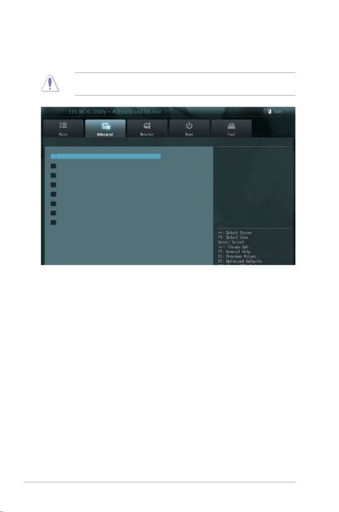
3.4
Advanced menu
The Advanced menu items allow you to change the settings for the CPU and other
system devices.
CAUTION: Be cautious when changing the settings of the Advanced menu
Items. Incorrect field values can cause the system to malfunction.
> CPU Configuration
> IDE
Configuration
> USB Configuration
> APM
> Panel Controller
> DIO Function
> North Bridge LVDS Config
Select
> Onboard Devices
Configuration
CPU Configuration Parameters
3.4.1
The items in this menu show the CPU-related information that the BIOS
automatically detects.
Hyper-threading [Enabled]
The Intel Hyper-Threading Technology allows a hyper-threading processor to
appear as two logical processors to the operating system, allowing the operating
system to schedule two threads or processes simultaneously.
[Enabled]
[Disabled]
[Enabled]
Two threads per activated core are enabled.
Only one thread per activated core is enabled.
Allows legacy operating systems to boot even without support for
CPUs with extended CPUID functions.
Disables this function.
CPU Configuration
Limit CPUID Maximum [Disabled]
[Disabled]
3-6
faytech Motherboard

3.4.2
While entering Setup, the BIOS automatically detects the presence of SATA devices.
The SATA Port items show Not Present if no SATA device is installed to the
corresponding SATA port.
SATA Controller(s) [Enabled]
[Disabled]
[Enabled]
Disables the onboard SATA controllers.
Enables the onboard SATA controllers.
IDE Configuration
Configure SATA as [IDE]
[IDE]
Allows you to set the SATA configuration.
[AHCI]
Set to [IDE] when you want to use the Serial ATA hard disk drives as
Parallel ATA physical storage devices.
Set to [AHCI] when you want the SATA hard disk drives to use the AHCI
(Advanced Host Controller Interface). The AHCI allows the onboard
storage driver to enable advanced Serial ATA features that increases
storage performance on random workloads by allowing the drive to
internally optimize the order of commands.
3.4.3
The items in this menu allow you to change the USB-related features.
NOTE: The USB Devices item shows the auto-detected values. If no USB device is
detected, the item shows None.
USB Configuration
EHCI Hand-off [Disabled]
[Enabled]
[Disabled]
Enables the support for operating systems without an EHCI hand-off
feature.
Disables the function.
3.4.4
[Power On]
[Power Off]
APM
The system goes into on state after an AC power loss.
The system goes into off state after an AC power loss.
The system goes into either off or on state, whatever the system state
was before the AC power loss.
Disables the PCIE devices to generate a wake event.
Enables the PCIE devices to generate a wake event.
Restore AC Power Loss [Power Off]
[Last State]
Power On By PCIE [Disabled]
[Disabled]
[Enabled]
Chapter 3: BIOS setup
3-7

Power On By Ring [Disabled]
[Disabled]
[Enabled]
Disables Ring to generate a wake event.
Enables Ring to generate a wake event.
3.4.5
Panel Controller (AMD®GPU only)
Backlight Brightness Setting [75]
Allows you to set the backlight brightness. Select a larger number for a brighter
backlight. Configuration options: [0][25][50][75][100]
3.4.6
DIO Function
GPIO 1~8 [Input]
Allows you to configure the digital signal of the GPIO (General Purpose Input/
Output) pins 1~8. Configuration options: [Input] [Output High] [Output Low]
3.4.7
North BridgeLVDS Config Select (AMD®GPU only)
LVDS Panel Config Select [1024x768]
Allows you to configurethe resolution for the LVDS panel. Configuration options:
[800x600 18bit] [800x480 18bit] [1024x768 24bit] [1280x800 18bit] [1280x1024
48bit] [1440x900 48bit] [1680x1050 48bit] [1920x1080 48bit]
EDID Panel Option [Enabled]
Enables or disables the EDID panel. Configuration options: [Enabled] [Disabled]
3.4.8
Onboard Devices Configuration
Onboard WLAN [Enabled]
[Enabled]
[Disabled]
[Enabled]
Enables the onboard wireless LAN / WiMAX.
Disables the onboard wireless LAN / WiMAX.
Enables the onboard audio controller.
Disables the controller.
Onboard Audio [Enabled]
[Disabled]
RS Mode [RS232]
Allows you to configure the serial communications standard of serial port (COM)
1. Configuration options: [RS232] [RS422] [RS485]
Onboard LAN [Enabled]
[Enabled]
[Disabled]
Enables the Realtek LAN controller.
Disables the controller.
3-8
faytech Motherboard
Onboard LAN Boot ROM [Disabled]
This item appears only when you set the Onboard LAN item to [Enabled] and
allows you to enable or disable the Boot ROM of the onboard LAN controller.
Configuration options: [Enabled] [Disabled]
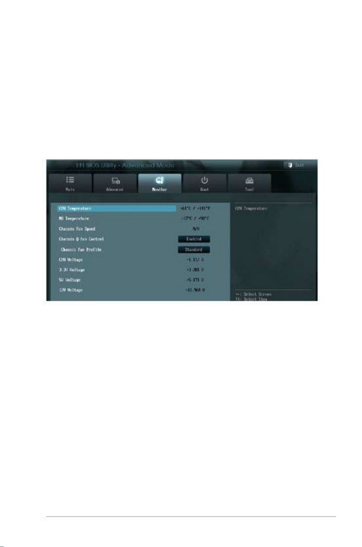
3.5
Monitor menu
The Monitor menu displays the system temperature/power status, and allows you
to change the fan settings.
3.5.1
The onboard hardware monitor automatically detects and displays the CPU
and motherboard temperatures. Select Ignore if you do not wish to display the
detected temperatures.
CPU Temperature / MB Temperature [xxxºC/xxxºF]
3.5.2
The onboard hardware monitor automatically detects and displays the chassis
fan speed in rotations per minute (RPM). If the fan is not connected to the
motherboard, the field shows N/A.
Chassis Fan Speed [xxxx RPM] or [N/A]
Chapter 3: BIOS setup
3-9
3.5.3
[Disabled]
[Enabled]
Chassis Q-Fan Control [Enabled]
Disables the Chassis Q-Fan control feature.
Enables the Chassis Q-Fan control feature.
Chassis FanProfile [Standard]
This item appears only when you enable the Chassis Q-Fan Control feature and
allows you to set the appropriate performance level of the chassis fan.
[Standard]
[Silent]
[Turbo]
Sets to [Standard] to make the chassis fan automatically adjust
depending on the chassis temperature.
Sets to [Silent] to minimize the fan speed for quiet chassis fan
operation.
Sets to [Turbo] to achieve maximum chassis fan speed.
3.5.4
The onboard hardware monitor automatically detects the voltage output through
the onboard voltage regulators. Select Ignore if you do not want to detect this item.
CPU Voltage, 3.3V Voltage, 5V Voltage, 12V Voltage
3.6
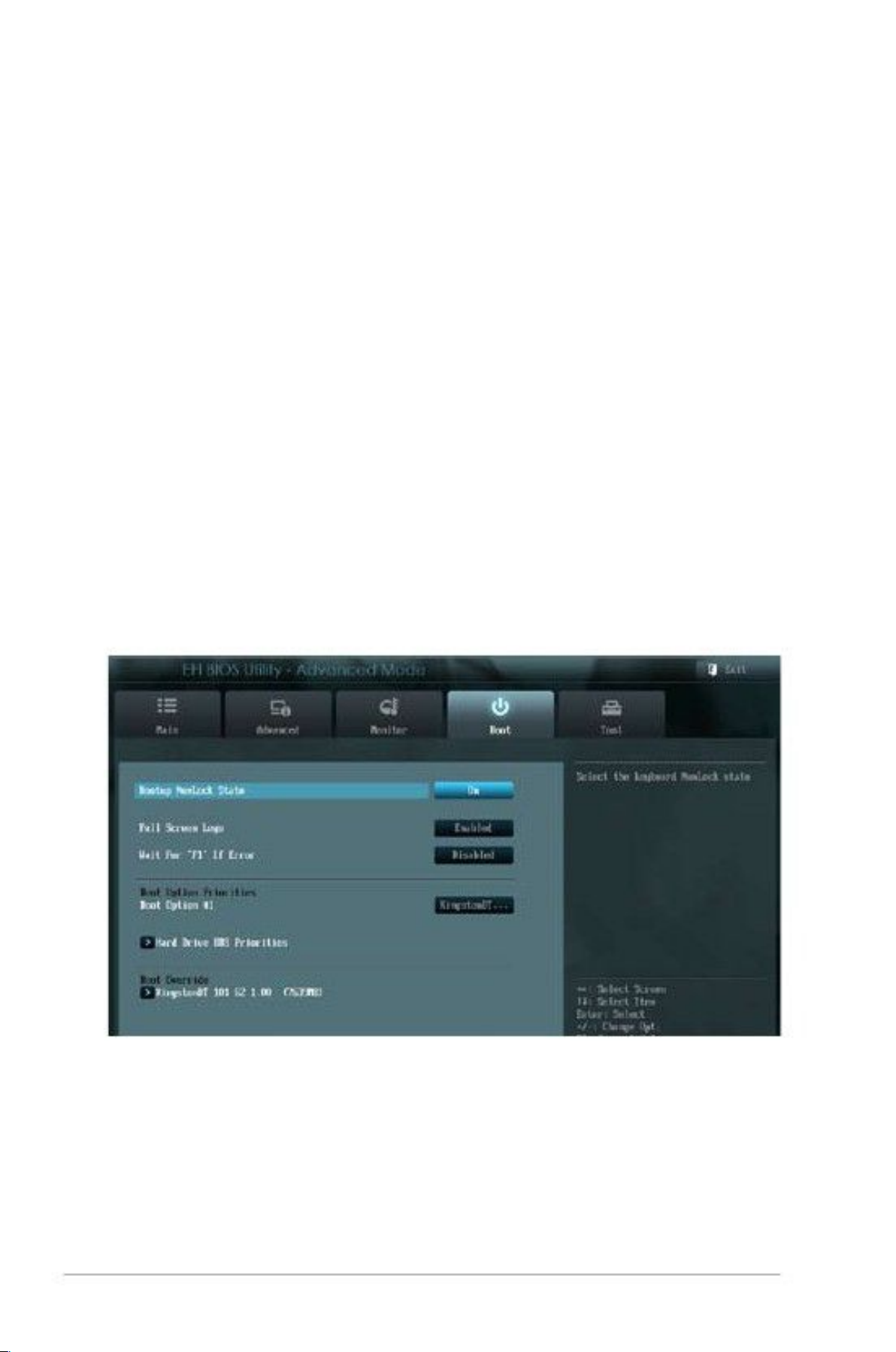
Boot menu
The Boot menu items allow you to change the system boot options.
3.6.1
[On]
[Off]
Bootup NumLock State [On]
Sets the power-on state of the NumLock to [On].
Sets the power-on state of the NumLock to [Off].
3-10
faytech Motherboard

3.6.2
3.6.3
3.6.4
[Enabled]
Full Screen Logo [Disabled]
[Disabled]
Enables the full screen logo display feature.
Disables the full screen logo display feature.
When this item is set to [Enabled], the system waits for the F1 key to be pressed
When error occurs. Configuration options: [Disabled] [Enabled]
These items specify the boot device priority sequence from the available devices.
The number of device items that appears on the screen depends on the number of
devices installed in the system.
NOTES:
•
•
To selectthe boot device during system startup, press <F8> after the first
screen appears.
To access Windows OS in Safe Mode, press <F8> after POST.
Wait for ‘F1’ If Error [Enabled]
Boot Option Priorities
3.6.5
These items displays the available devices. The number of device items that
appears on the screen depends on the number of devices installed in the system.
Click an item to start booting from the selected device.
Boot Override
3.7
Tools menu
The Tools menu items allow you to configure options for special functions. Select
an item then press <Enter> to display the submenu.
EZ Flash 2 Utility
Allows you to run EZ Flash 2. Press [Enter] to launch the EZ Flash 2 screen.
Chapter 3: BIOS setup
3-11

3.8
Exit menu
The Exit menu items allow you to load the optimal default values for the BIOS
items, and save or discard your changes to the BIOS items. You can access the
EZ Mode from the Exit menu.
Load Optimized Defaults
This option allows you to load the default values for each of the parameters on the
Setup menus. When you select thisoption or if you press <F5>, a confirmation
window appears. Select Yes to load the default values.
Save Changes & Reset
Once you are finished making your selections, choose this option from the Exit
menu to ensure the values you selected are saved. When you select this option or
If you press <F10>, a confirmation window appears. Select Yes to save changes
and exit.
Discard Changes & Exit
This option allows you to exit the Setup program without saving your changes.
When you select this option or if you press <Esc>, a confirmation window appears.
Select Yes to discard changes and exit.
3-12
faytech Motherboard

Appendix
Notices
Federal Communications Commission Statement
This device complies with Part 15 of the FCC Rules. Operation is subject to the
following two conditions:
• This device may not cause harmful interference.
•
This equipment has been tested and found to comply with the limits for a Class
A digital device, pursuant to Part 15 of the FCC Rules. These limits are designed
to provide reasonable protection against harmful interference in a residential
installation. This equipment generates, uses and can radiate radio frequency
energy and, if not installed and used in accordance with manufacturer’s
instructions, may cause harmful interference to radio communications. However,
there is no guarantee that interference will not occur in a particular installation. If
this equipment does cause harmful interference to radio or television reception,
which can be determined by turning the equipment off and on, the user is
encouraged to try to correct the interference by one or more of the following
measures:
• Reorient or relocate the receiving antenna.
•
•
•
Increase the separation between the equipment and receiver.
This device must accept any interference received including interference that
may cause undesired operation.
Connect the equipment to an outlet on a circuit different from that to which the
receiver is connected.
Consult the dealer or an experienced radio/TV technician for help.
WARNING! The use of shielded cables for connection of the monitor to the
graphics card is required to assure compliance with FCC regulations. Changes
Or modifications to this unit not expressly approved by the party responsible for
compliance could void the user’s authority to operate this equipment.
DO NOT throw the motherboard in municipal waste. This product has been designed to
enable proper reuse of parts and recycling. This symbol of the crossed out wheeled bin
indicates that the product (electrical and electronic equipment) should not be placed in
municipal waste. Check local regulations for disposal of electronic products.
DO NOT throw the mercury-containing button cell battery in municipal waste. This symbol
of the crossed out wheeled bin indicates that the battery should not be placed in municipal
waste.
Appendix
A-1

KONTAKT / CONTACT
Kontaktdaten, RMA-Bearbeitung
Support-Nummer: +49 211 9954 8956
Global-Support: +86 755 89580612
Support-E-Mail: support@faytech.de
Hersteller-Internetseite: www.faytech.com
Europäisches Support- und Versandlager: faytech Service
Hans-Böckler Str. 10a, 37079 Göttingen
RMA-Bearbeitung
Wenden Sie sich bei einem mutmaßlichen Defekt bitte immer zunächst an uns. Unsere
ausgebildeten Fachkräfte helfen Ihnen gerne weiter. Liegt tatsächlich ein Defekt vor erhalten Sie
über support@faytech.de eine RMA-Nr. (Return Merchandise Authorization). Senden Sie das defekte Teil
mit deutlicher Anbringung der RMA-Nr. an obige Adresse ein. Zubehörteile wie Kabel, Adapter oder
Netzteile tauschen wir in der Regel unkompliziert vorab aus.
Bitte senden Sie die Ware immer frei an uns. Unfreie Ware (Kosten zahlt der Empfänger) nehmen wir
nicht an. In den ersten 30 Tagen nach Erstkauf übernehmen wir sämtliche Transportkosten für Sie.
Dafür senden wir ihnen per E-Mail mit der RMA- Nr. Einen Rücksendeschein zu. In der
restlichen Garantiezeit tragen wir die Rücksendegebühren.
Contact, RMA service (in English):
Support Number: +1 720 251 4158
Global Support: +86 755 89580612
Support E-Mail: support@faytech.com
Homepage: www.faytech.com
U.S.A. Warehouse: 121 Varick Street, 3rdFloor, New York, NY 10013
RMA-service:
If you think your faytech product has a defect please always contact us directly. Our trained after
sales service specialists can help you resolve your problems. Please check the manual and our
frequently asked questions before contacting us – you will usually find an answer to your question.
If there is a defect you can request an RMA number (Return Merchandise Authorization) at
support@faytech.com or via fax at +86-755- 89580613 (Chinese fax-number). Please attach in the
contact e-mail/fax your invoice and what problems you are experiencing. In reply, you will receive
an e-mail/fax with your RMA number and additional information. For accessories like cables,
adaptors or power supplies which are not working, we can usually send you a replacement before
receiving the damaged goods. For a defective product, we try to check and solve the problem within
3 days after receipt. Make sure that shipping has been paid before sending goods back to us. We do
not accept postage due packages at our service centers. Anything received with postage due will be
returned to you without any testing or resolution. Within the first 30 days after you buy a new faytech
product, we will refund your shipping costs for returned products. For the rest of the warranty period,
we will pay the shipping costs for any repaired or replaced items that we ship back to you.
 Loading...