

Page 1
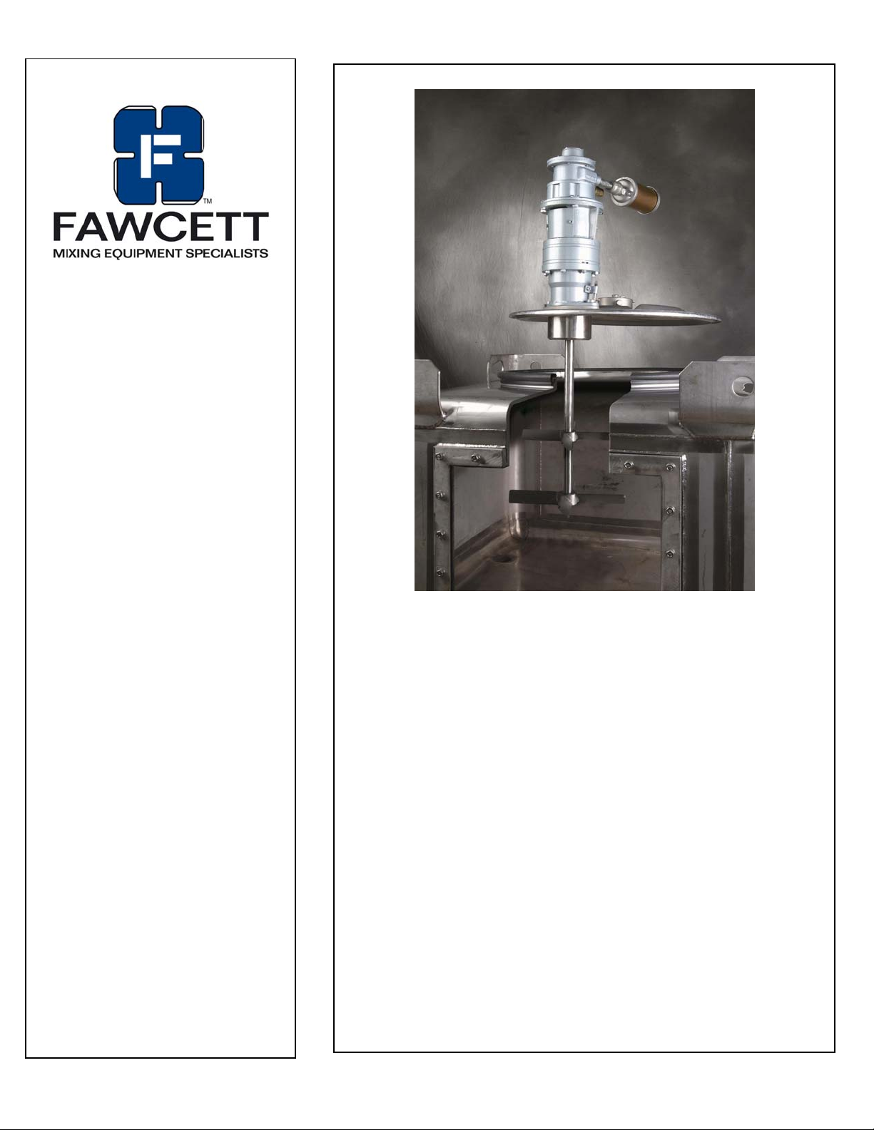
TRANS-MIX
TOTE MIXER
OWNERS
MANUAL
Warranty:
Our products are guaranteed against defective
materials and workmanship. We will repair or
replace such items as may prove defective at our
option. Warranty period is one year on items
manufactured by FAWCETT. On items not
manufactured by FAWCETT, the manufactures
warranty applies. All component parts of our
products are covered by this warranty, except for
normal wear items such as impellers. We cannot
be responsible fordamage or abuse to equipment
caused by improper installation or operation.
Warranties can also be voided by unauthorized
disassembly of equipment. For warranty repairs,
equipment is returned to FAWCETT at the
customer's expense; we will repair and return to
customerat our expense.Under no circumstances
will we allow labor charges or other expense to
repair defective merchandise. This warranty is
exclusive and is in lieu of all other warranties,
whether express or implied. FAWCETT shall not be
liable for any other damages, whether
consequential, indi rect, or incidental, arising from
the sale or use of its products.
TRANS-MIX SERIES
Contents: Page:
Model – Accessory Data 2
Safety, General & Receiving 3
Installation 4
Motor Operation / Maintenance 5/6
General Arrangement Drawing
Parts Lists
Detail Drawings
Reducer Maintenance
Order Form
Survey
FAWCETT Co., Inc.
3863 Congress Pkwy.
Richfield, OH
phone: 330.659.4187
fax: 330.659.6991
44286
web: www.fawcettco.com
Page 2

TRANS-MIX Series Tote Mixers
Model: 15-TM-3 Upper Assembly
15-TM-4 Lower Assembly
Upper P/N: 2156D3A-3.0
Lower P/N: 2156D4-62.5
Date: 10/2006
Order No.:
Motor:
Part No.: 104 NEMA
H.P.: 3.0 max
RPM: 500
Repair Kit #: K208
Accessories:
________________
________________
________________
Shaft(:
Part #’ : ZZ 106-62.5
________________
Turbine Blades:
Part #’s : MF-140T
MF-160T
________________
________________
FAWCETT, Inc. TRANS-MIXS Manual 03/06
Page 3

Safety
Please follow the below safety precautions. If there are
any questions, please call FAWCETT at 330 659-4187.
Please read this complete manual before trying to operate
your mixer. Failure to follow these instructions could result
in serious bodily injury or death.
• Do not touch moving parts while mixer is operating.
Do not wear loose-fitting clothes or jewelry around an
operating mixer. Keep all hands, feet, clothes, neckties,
necklaces and other objects clear of moving parts.
• Never move the unit with the motor running.
• Have a qualified individual bring air to your unit.
• Never run the unit in open air.
• Never adjust the speed without the unit running.
Air Motor Safety:
The air motor is designed to be driven by compressed air
and under no circumstances be driven with any other
gases. Fluids, particles, solids or any substance mixed
with air, particularly combustible substances likely to
cause explosions, must not drive air motor.
• Air motor is designed for air only. Do not allow corrosive
gases or particulate material to enter motor. Water vapor,
oil-based contaminants, or other liquids must be filtered
out.
• Do not use a hammer or force coupling onto shaft when
installing drive onto air motor. This causes end thrust that
could damage air motor.
• Ambient temperature should not exceed 200°F.
• Beware of any exposed and/or movable parts to prevent
personal and/or property damage.
• Solid or liquid material exiting unit can cause eye or skin
damage. Keep away from air stream.
• Always disconnect air supply before servicing.
• Do not allow air motor to “run free” at high speeds with
no loads. Excessive internal heat build-up, loss of
internal clearances and rapid motor damage will result.
• Some models may exceed 85dB (A) sound level.
Hearing protection should be worn when in close
proximity to these models.
Receiving
Before removing any packing, visually inspect the exterior
of the shipment for any sign of damage. Should there be
any damage, bring it to the attention of the delivering UPS
or truck line and note the same on the receiving ticket.
Should there be damage you must place a claim with the
truck line. They are the only ones who will pay for the
damage done and you are the only one who can place
that claim.
FAWCETT, Inc. LS manual 4/18/2007 page 3 of 7
Page 4
Installation
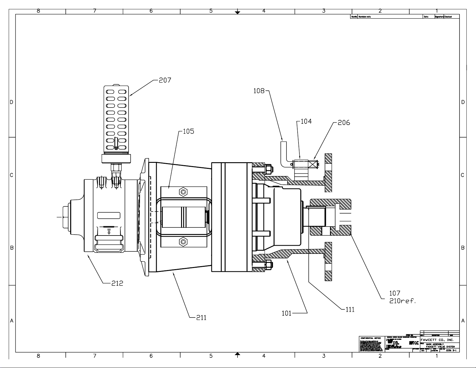
Your new mixer is supplied partially assembled. For
more information, see the parts list pages for general
arrangement drawings.
Turbine blades:
To install the turbine blade, back off the set screw as
far as possible without removing them. Insert mixing
shaft into the bore and tighten the set screw firmly to
secure the turbine blade to the shaft.
Turbine blade Placement:
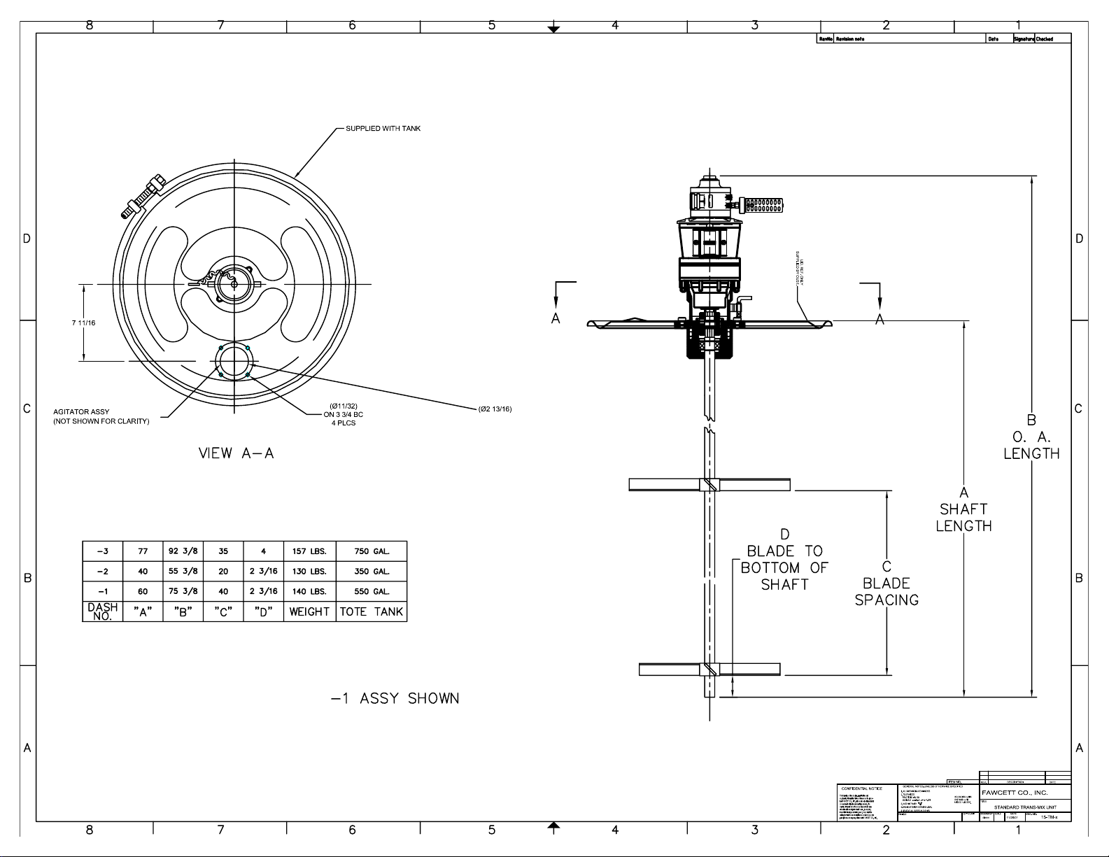
See the General arrangement drawing included with
this manual.
The drawing guideline is a “rule of thumb” and may not
be the best for your situation. Experimenting with
turbine blade placement may provide your best results.
Assembly:
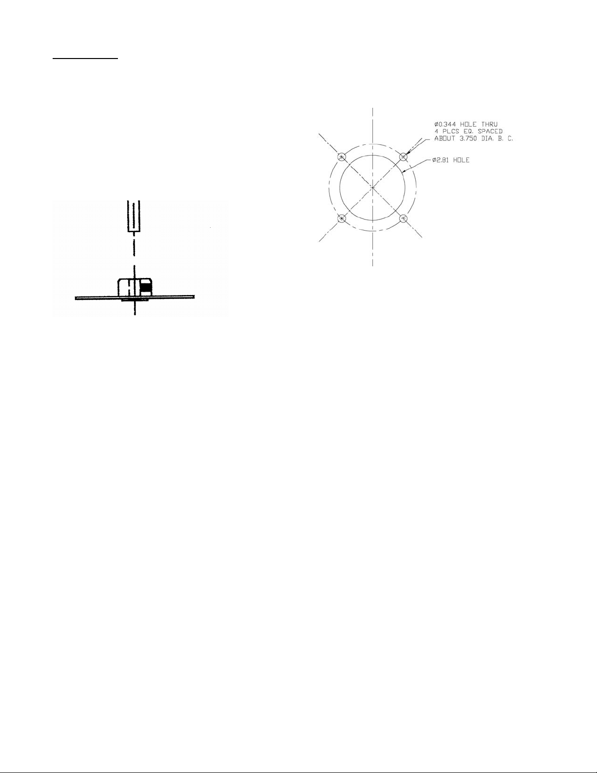
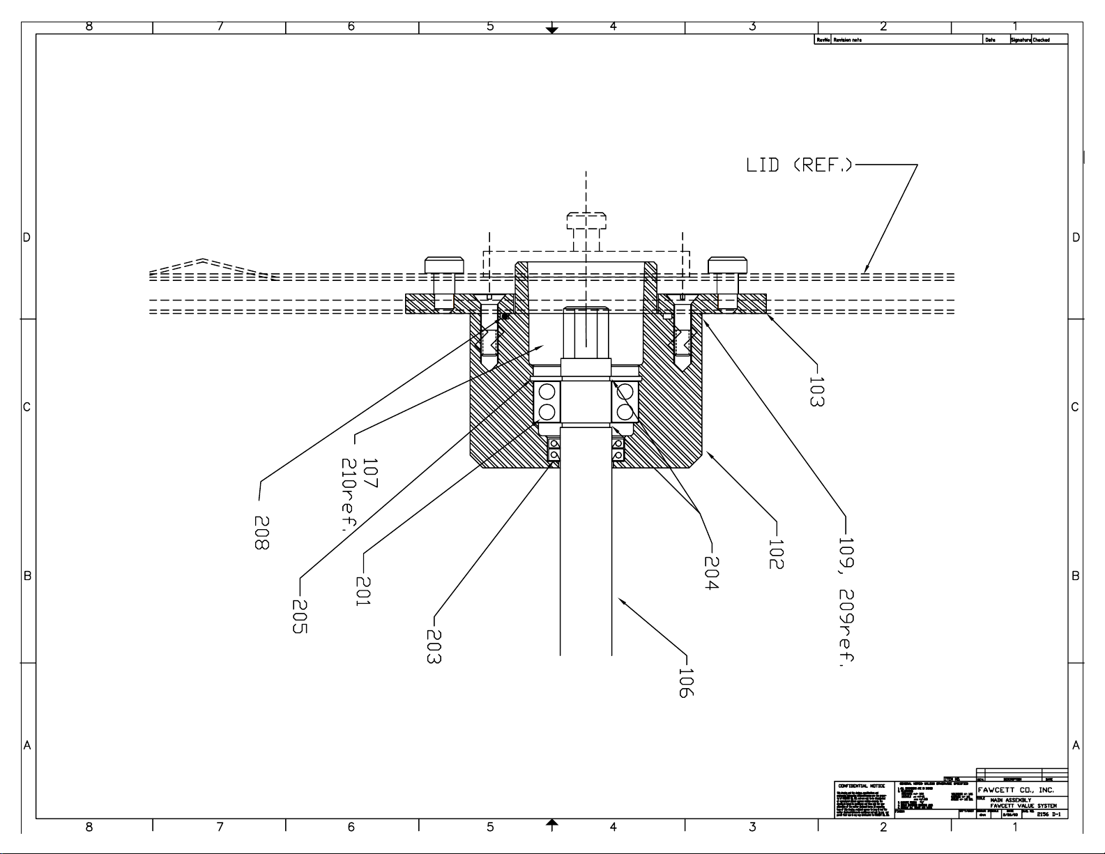
1.) Alter container lid to accept lower bearing
housing per drawing below.
2.) Place Teflon gasket on lower housing and
insert through opening in lid.
3.) Place tabbed bracket over lower housing and
fasten with )4) 5/16-18 flat head screws
4.) Replace lid on tank.
5.) Place upper drive unit onto hex portion of drive
shaft, turn to locate against pins.
6.) Lift lock pin and drop into loacing position
7.) Assemble air hose to inlet port of the motor.
8.) Make sure air control valve is closed.
Mixer is now ready to operate.
FAWCETT Co, Inc. LS manual 03/06 page 4 of 7
Page 5

FAWCETT Co, Inc. LS manual 03/06 page 4 of 7
Page 6

LUBRICATED AIR MOTORS
OPERATION & MAINTENANCE
IMPORTANT: PLEASE READ THIS MANUAL AND
SAVE FOR FUTURE REFERENCE.
Thank you for purchasing this Fawcett product. It is
manufactured to the highest standards using quality materials.
Please follow all recommended maintenance, operational and
safety instructions and you will receive years of trouble free
service.
Product Use Criteria:
• Operate at temperature up to 250ºF (121ºC).
• Protect unit from dirt and moisture.
• Use ONLY compressed air to drive motor.
• Air lines connected to motor should be the same size or the
next size larger than the intake port for efficient output and
speed control.
• Protect all surrounding items from exhaust air.
• Bearings are grease packed.
• Use #AD220 or a detergent SAE#10 automotive engine oil
for lubricating.
General information
• Clearances: Model Total End Clearance (in/mm) Top
Clearance (in/mm)
LS101 0.0020/0.0508 0.0015/0.0381
LS102 0.0025/0.0635 0.0015/0.0381
LS103 0.0035/0.0889 0.0015/0.0381
LS104 0.0035/0.0889 0.0015/0.0381
LS105 0.0048/0.1219 0.0015/0.0381
• Vane Life: Depends upon speed, operating pressure and
motor maintenance.
• Operating Pressure: 100 psi or below (7 bar)
Correct installation is your responsibility. Make sure you
have the proper installation conditions and that the specified
installation clearances are available.
INSTALLATION
Connection
Check the direction of the motor airflow. A single rotation motor
will operate properly only in one direction. Install a filter in the
air line before the connection to the motor. Connect lines to
motor in the proper direction. A reversible motor will work
equally well in both directions. Connecting a 4-way valve with
piping to both air ports of the motor will make reversing
possible.
Do not add any thrust to the end or side of the shaft when
making connections. Do not use a hammer on the shaft or
connections.
Mounting
This product can be installed in any orientation. Mount the
motor to a solid base plate that is mounted to a stable, rigid
operating surface. Install a pressure regulator or simple shutoff valve to control motor.
Consult your Fawcett Co. representative for additional filter
recommendations. Install a moisture trap and filter in the air
line ahead of the motor. For the most efficient output and
control of speed, use air lines that are the same size or the
next pipe size larger than the motor intake port. An
automatic air line lubricator should be installed 18” or as
close as possible in the air line just ahead of the motor.
Adjust the lubricator to feed one drop of oil for every 50-75
CFM of air moving through the motor. Air consumption at
various speeds and pressures are available from your local
Fawcett representative.
It is your responsibility to operate this product at
recommended speeds, loads and room ambient
temperatures. Do not run the motor at high speeds with
no load. This will result in excessive internal heat that
may cause motor damage.
The starting torque is less than the running torque. The
starting torque will vary depending upon the position of the
vanes when stopped in relation to the air intake port. Use a
pressure regulator and/or simple shut-off valve to regulate
the motor’s speed and torque. This will provide the required
power and will conserve air.
OPERATION
Injury Hazard
Air stream from product may contain solid or liquid
material that can result in eye or skin damage. Do Not
use combustible gases to drive this motor. Wear hearing
protection. Sound level from motor may exceed 85db(A).
Failure to follow these instructions can result in burns,
eye injury or other serious injury.
Air Power:
Check to ensure the air valve is in the closed position, then
connect air supply. Check rotation to be sure the mixer shaft
is rotating in a clockwise direction, looking downward into the
container.
Once the mixer is in the container, it is now safe to operate.
CAUTION:
• Never run mixer without an Impeller.
• Never run the impeller in open air.
• Never run impeller outside a container.
1FAWCETT, Inc. LS manual 03/06 Page 5 of 7
Page 7

MAINTENANCE
Injury Hazard
Disconnect air supply and vent all airlines. Wear eye
protection when flushing this product. Air stream from
product may contain solid or liquid material that can result
in eye or skin damage. Flush this product in a wellventilated area. Do Not use kerosene or other combustible
solvents to flush this product. Failure to follow these
instructions can result in burns, eye injury or other
serious injury.
It is your responsibility to regularly inspect and make
necessary repairs to this product in order to maintain
proper operation.
Check intake and exhaust filters after first 500 hours of
operation. Clean filters and determine how frequently filters
should be checked during future operation. This one procedure
will help assure the product’s performance and service life.
Flushing
Flushing this product to remove excessive dirt, foreign
particles, moisture or oil that occurs in the operating
environment will help to maintain proper vane performance.
Flush the motor if it is operating slowly or inefficiently.
Use only #AH255B Flushing Solvent. DO NOT use
kerosene or ANY other combustible solvents to flush this
product.
Lubrication
Use only #AD220 or a detergent SAE #10 automotive engine
oil for lubricating. Lubricating is necessary to prevent rust on all
moving parts. Excessive moisture in the air line may cause rust
or ice to form in the muffler when air expands as it passes
through the motor. Install a moisture separator in the air line
and an after cooler between compressor and air receiver to
help prevent moisture problems.
Manual Lubrication
Shut the air motor down and oil after every 8 hours of
operation. Add 10-20 drops of oil to the air motor intake port.
Automatic Lubrication
Adjust inline oiler to feed 1 drop of oil per minute for high
speed or continuous duty usage. Do Not overfeed oil or
exhaust air may become contaminated.
1. Disconnect air line and muffler.
2. Add flushing solvent directly into motor. If using liquid
solvent, pour several tablespoons directly into the intake port. If
using #AH255B, spray solvent for 5-10 seconds into intake
port.
3. Rotate the shaft by hand in both directions for a few
minutes.
4. You must wear eye protection for this step. Cover
exhaust with a cloth and reconnect the air line. Slowly apply
pressure until there is no trace of solvent in the exhaust air.
5. Listen for changes in the sound of the motor. If motor
sounds smooth, you are finished. If motor does not sound like
it is running smoothly, installing a service kit will be required.
(See “Service Kit Installation”).
Check that all external accessories such as relief valves or
gauges are attached and are not damaged before
operating product.
Shutdown
It is your responsibility to follow proper shutdown
procedures to prevent product damage.
1. Turn off air intake supply.
2. Disconnect plumbing.
3. Remove air motor from connected machinery.
4. Wear eye protection. Keep away from air stream. Use
clean, dry air to remove condensation.
5. Lubricate motor with a small amount of oil in chamber.
Rotate shaft by hand several times.
6. Plug or cap each port.
7. Coat output shaft with oil or grease.
8. Store motor in a dry environment.
www.fawcettco.com
1FAWCETT, Inc. LS manual 03/06 Page 6 of 7
Page 8
78
6
RevNoRevision not
2345
e
1
Dat
Checked
e
Signature
SUPPLIED WITH TANK
D
7 11/16
C
AGITATOR ASSY
(NOT SHOWN FOR CLARITY)
B
-
-
-
DAS
NO
D
C
(∅11/32
ON 3 3/4 BC
4 PLC
S
S
U
PP
L
L
I
D
I
E
,
D
R
E
BY
F
.
CU
O
N
S
L
T
Y
.
A
)
(∅2 13/16
)
A
B
O. A.
VIEW A-
A
LENGT
H
A
SHAFT
D
77
3
2
1
H
.
92
40
55 3/8
60
75
"B""A" "C" "D"
3/
3/
8
8
35 4
20
2
3/16
40
3/16
2
157 LBS.
130 LBS.
140 LBS.
WEIGH
750 GAL
350 GAL
550 GAL
T
TOTE TANK
.
.
.
LADE T
B
BOTTOM O
SHAFT
O
B
C
LAD
F
SPACING
LENGT
E
H
B
-1 ASSY SHOW
A
78
6
N
A
CONFIDENTIAL NOTICE
This drawing and the designs, specifications
and
engineering information disclosed hereon are the proper-
ty of FAWCETT CO
., INC.
and are no
t to be disseminat
or reproduced wit
hout express written consen
t. The
drawing is l
oaned in confi
dence and then only for con-
sideration of the matter disclosed heron
. In accepting
l
oan of this drawing, recipient agrees to keep it and the
matter disclosed hereon in confi
dence and no
t to use nor
permit their use in any way detrimental to FAWCETT CO., INC.
REV.
FAWCETT CO
8
TITLE
.
DRAWN
T
d
mm
BY
DESCRIPTION
STANDARD TRANS-MIX UNI
SCALE
11/26/01
ITEM NO
.
xxx =+/-.005
ESS OTHERWISE
ES
010R.
SPECIFIED
.
WELDMENTS +/- 1/16
CASTINGS +/- 1/
ANGLES +/- 1/2 DEG
QT'Y/UNI
GENERAL NOTES: UNL
1. ALL DIMENSIONS ARE IN INCH
. TOLERANCES
2
FRACTIONS =+/- 1/
64
DECIMALS
.xx =+/-.
3. MACHINE FINISH
4. BREAK EXTERIOR CORNERS .
5. REMOVE ALL BURRS AND CHIPS
FINIS
H
01
125
ed
2345
DAT
E
., INC.
DAT
T
E
DWG. NO.
15-TM-
x
1
Page 9
FAWCETT CO.
CUSTOMER:
B/M No: 2156 D1
BY: DMM
SHEET: 1
DATE: 1/23/2003
DESCRIPTION: TRANSMIX SYSTEM Manufactured Parts
ITEM No.
No. REQ'D PART NO. NAME DESCRIPTION
101 1 2156 C4 MOTOR MOUNT WLDMNT
102 1 2156 C1 BEARING HOUSING
103 1 2156 C2 CLAMP PLATE
104 1 2156 C3 LOCK BRKT WELDMENT
105 2 2156 A2 SHOULDERED PIN
106 1 2156 B2 IMPELLER SHAFT
107 1 2156A1-1 COUPLING RED SPOT USES 2156 A1-2 (MAKE -2 & CUT DOWN)
108 1 2156 A9 LOCK PIN
109 2 2156 A4 GASKET
110 A/R 2156 B1 REDDY SYSTEM ADAPTER
111 A/R 2156 C6 12" TURBINE BLADE
112 A/R 2156 C7 14" TURBINE BLADE
113 A/R 2156 C8 16" TURBINE BLADE
114 1 2156A10 KEY
115 2 2156A11 MOTOR MOUNT COVER
116 1 2156A12 HYD. ADAPTER PLATE
rev.#1,
Page 10
FAWCETT CO.
CUSTOMER:
B/M No: 2156 D1
BY: DMM
SHEET: 1
DATE: 1/23/2003
DESCRIPTION: TRANSMIX SYSTEM COMMERCIAL PARTS
ITEM No.
No. REQ'D PART NO. NAME DESCRIPTION
201 1 BEARING ZZAPP 5205-2RS1
202
203 2 SEAL ZZACA MSE1000-250-25-01
204 2 H.D. EXT. RET. RING ZZAPP SHR-98-STPA
205 1 INT. RET. RING ZZAPP HO-218-STPAS
206 1 S.S. COMPR. SPRING ZZMCM 9435K99
207
208 1 VITON "O" - RING ZZMCM 9464234
209 1 GASKET *** SEE ITEM 109 ***
210 REF COUPLING *** SEE ITEM 107 ***
211 1 GEAR BOX ZZSUM CNFJ 4100Y 6:1
212 REF AIR MOTOR LS-130NEMA, LS-104NEMA or LS-105NEMA
212 REF HYDRAULIC MOTOR LAMINA# A25 FMO
212 REF ELECTRIC MOTOR ZZBAL VM3558 or ZZBAL VM6561
rev.#1,
Page 11
FAWCETT CO.
CUSTOMER:
B/M No: 2156 D1
BY: DMM
SHEET: 2
DATE: 1/23/2003
DESCRIPTION: TRANSMIX SYSTEM COMMERCIAL PARTS
ITEM No.
No. REQ'D PART NO. NAME DESCRIPTION
213 REF LATCH ASSEMBLY See 2156C3 & 2156A9
214 REF MOUNT See 2156C4
215 REF TOP PLATE See 2156C2
216
217 REF TOP MOUNT ASS'Y See 2156C2
218 REF REDDY ADPT RING See 2156B1
rev.#1,
Page 12
78
6
RevNoRevision not
2
0
7
2345
e
1
Dat
Checked
e
Signature
108
D
1
0
4
206
D
105
C
B
C
B
212
107
10ref
2
11
A
78
6
2
101
111
CONFIDENTIAL NOTICE
Th
i
s drawing and the designs, specifications and
eng
i
neering information disclosed hereon are the proper-
ty of FAWCETT CO., INC.
and are not to be disseminated
i
thout express written consent. The
or reproduced w
drawing is loaned in confidence and then only for cons
i
deration of the matter disclosed heron. In accepting
l
oan of this drawing, recipient agrees to keep it and the
matter disclosed hereon in confidence and not to use nor
perm
i
t their use in any way detrimental to FAWCETT CO., INC.
2345
.
ALL DIMENSIONS ARE IN INCHES
1
.
2
FRACT
DEC
3. MACHINE FINISH
.
4
.
5
FINISH
GENERAL NOTES: UNLESS OTHERWI
TOLERANCES
I
ONS =+/- 1/64
I
MALS .xx =+/-.0
.
xxx =+/-.00
1
25
BREAK EXTERIOR CORNERS .010R.
REMOVE ALL BURRS AND CHIPS
.
A
I
TEM NO
.
SE SPECIFIED
W
ELDMENTS +/- 1/16
1
CASTINGS +/- 1/8
5
ANGLES +/- 1/2 DEG
QT'Y/UNIT
DESCRIPTION
V
.
RE
FAWCETT CO., INC.
TITLE
.
MAIN ASSEMBLY
FAWCETT VALUE SYSTEM
SCALE
DRAWN BY
DATE
DWG. NO
2/26/03
dmm
1
.
2156 D-
DATE
1
Page 13
78
6
RevNoRevision not
2345
e
1
Dat
Checked
e
Signature
LID (REF.)
D
1
0
3
C
1
2
0
1
7
0
ref
D
C
2
0
8
B
2
0
5
.
2
0
1
2
0
3
1
0
6
2
0
4
1
0
2
1
0
9
,
2
0
9ref
.
B
.
2156 D-
A
DATE
1
A
I
TEM NO
.
SE SPECIFIED
W
ELDMENTS +/- 1/16
1
CASTINGS +/- 1/8
5
ANGLES +/- 1/2 DEG
1
25
QT'Y/UNIT
FINISH
2345
GENERAL NOTES: UNLESS OTHERWI
1
.
ALL DIMENSIONS ARE IN INCHES
.
TOLERANCES
2
I
ONS =+/- 1/64
FRACT
I
MALS .xx =+/-.0
DEC
.
xxx =+/-.00
3. MACHINE FINISH
4
.
BREAK EXTERIOR CORNERS .010R.
.
REMOVE ALL BURRS AND CHIPS
5
CONFIDENTIAL NOTICE
Th
i
s drawing and the designs, specifications and
i
neering information disclosed hereon are the proper-
eng
ty of FAWCETT CO., INC.
and are not to be disseminated
or reproduced w
i
thout express written consent. The
drawing is loaned in confidence and then only for cons
i
deration of the matter disclosed heron. In accepting
l
oan of this drawing, recipient agrees to keep it and the
matter disclosed hereon in confidence and not to use nor
perm
i
t their use in any way detrimental to FAWCETT CO., INC.
78
6
DESCRIPTION
RE
V
.
FAWCETT CO., INC.
TITLE
.
MAIN ASSEMBLY
FAWCETT VALUE SYSTEM
SCALE
DRAWN BY
DATE
DWG. NO
2/26/03
dmm
1
Page 14
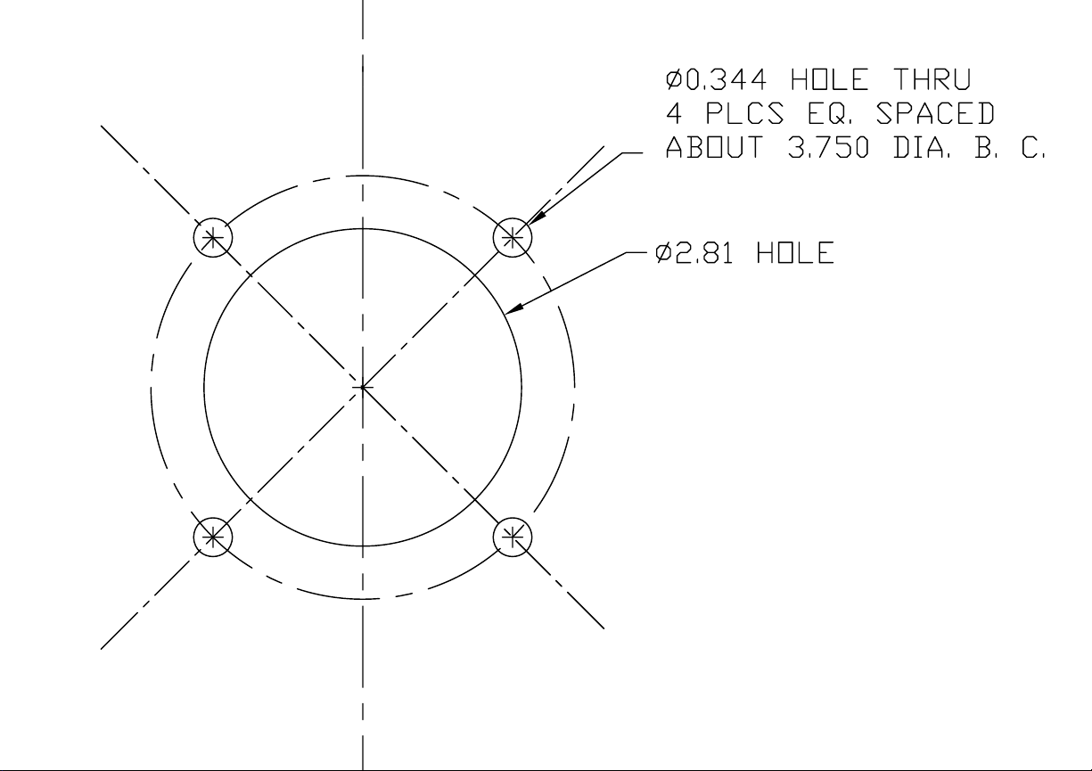
0.344 HOLE THRU
∅
.
4 PLCS EQ
ABOUT 3
∅2.81 HOLE
SPACED
.
750 DIA. B. C
.
Page 15
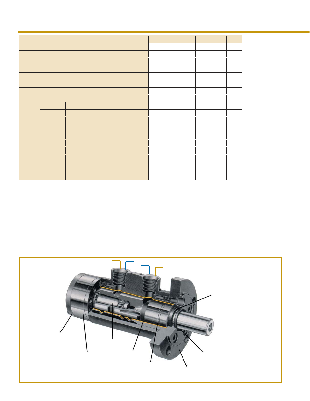
GEROTOR MOTOR
DISPLACEMENT
(cubic inches per revolution)
A25 A37 A50 A62 A100 A125
0.82 1.16 1.53 1.88 3.11 3.73
GEROTOR SIZE (Inches) 0.250 0.375 0.500 0.625 1.000 1.250
CAPACITY (Maximum GPM) 8 8 8 8 8 8
SPEED (Maximum RPM) 2255 1592 1206 982 595 495
TORQUE (Maximum Inch-pounds) 149 222 284 363 570 656
MAXIMUM SIDE LOAD (pounds-force) 300 300 300 300 300 300
MAXIMUM PUSH FORCE (pounds-force) 500 500 500 500 500 500
MAXIMUM PULL FORCE (pounds-force) 300 300 300 300 300 300
F Standard Flange - Short Shaft 3.55 3.55 3.55 3.60 3.80 3.90
FMO Standard Flange - Long Shaft 3.65 3.65 3.65 3.70 3.90 4.00
FM Foot Mount - Long Shaft 6.15 6.15 6.15 6.20 6.40 6.50
F-T Turned Down Flange - Short Shaft 3.10 3.10 3.10 3.15 3.35 3.45
Sample
Motor
Weights
(pounds)
FMO-T Turned Down Flange - Long Shaft 3.20 3.20 3.20 3.25 3.45 3.55
FA-A Aluminum Body & Flange - Short Shaft 2.45 2.45 2.45 2.50 2.70 2.80
FMOA-A Aluminum Body & Flange - Long Shaft 2.55 2.55 2.55 2.60 2.80 2.90
FA-TA
FMOA-TA
Aluminum Body & Turned Down
Flange - Short Shaft
Aluminum Body & Turned Down
Flange - Long Shaft
2.30 2.30 2.30 2.35 2.55 2.65
2.40 2.40 2.40 2.45 2.65 2.75
Please note:
The capacity (GPM),
speed (RPM), and
output torque (IN-LBS)
provided in the table
are maximum quantities for
speci? c gerotor
sizes.
For motor operating
characteristics under
various application
requirements - see
"Selection Guide"
tables on pages 4
and 5.
The rotor gear of these low-weight motors rolls through four complete "CYCLES" for each revolution of the output shaft. Thus,
four times greater torque at one-fourth of the conventional speed
is obtained without the use of gear reducers. In other words, with
hydraulic motors the same amount of torque is assured as you
would get from a much larger ordinary motor that is considerably
more expensive.
Of considerable importance to application design engineers is the
smooth rotation and long life of these unique motors. Because the
motors have five fluid chambers, the inherent four-to-one ratio
provides twenty fluid power cycles for each revolution of the
output shaft. This feature assures a distinct addition, these
motors have only three moving parts (motor shaft, spline drive,
gerotor star) - this greatly extends the service life.
Within the broad range of each gerotor, any torque or speed can
be readily secured. Also the various sizes of gerotors available
provide a torque range from 0 to 656 inch-lbs. and R.P.M.
ranging from 0 to 2255. High selectivity to exactly meet
requirements is inherent in these motors.
We recommend parallel circuits versus series circuits, because
the back pressure generated cannot exceed 300 psi.
Recommended Oil: Mobil
® DTE 13 (ISO-32 Hydraulic Oil).
Arrows show how
the shaft will sping
depending on fluid
flow through the
motor.
Lip Seal
Positive
Metal-to-Metal
Sealing
Matched
Gerotor
Positive
Splined Drive
Lamina-
Bronze
Bearing
Surface
Needle
Bearing
Sealed Against
Contamination
Six Styles of Mounts
(see page 2)
6
Page 16

ORDER MOTOR BY
SIZE WITH SUFFIX:
"F" Flange Mount
Short Shaft
"FM" Pedestal Foot
Mount
"FMO" Flange Mount
Long Shaft
Hydraulic Motors
have a "letter-numberletter" designation that
indicates the type of
motor, size of gerotor,
and mounting method
required. For example: a
motor having a 1/2 inch
gerotor and requiring
flange mounting short
shaft, would be idicated
as A50F.
Order motor with optional
features according to the
following suffixes:
Turned down flange
"-T"
"-2-BOLT"
"-4-BOLT"
"-A"
"-TA"
"-1"
"-2"
"-DT"
"-K"
"V"
Refer to example on
bottom of page 2.
When selecting your
motor for a specific application, you must remember that the peak
motor torque and RPM
must be sufficient to
meet the most severe
demands of the application.
4
Oval Flange
Square Flange
Aluminum round flange
Aluminum turned
down flange
One flat on shaft
Two flats on shaft
Shaft end tapped
Longer Key
with Viton seal
TORQUE (Inch-pounds)
G
RPM
P
and
TORQUE
M
1
2
3
4
5
6
7
8
RPM
TORQUE
RPM
TORQUE
RPM
TORQUE
RPM
TORQUE
RPM
TORQUE
RPM
TORQUE
RPM
TORQUE
RPM
TORQUE
100 200 300 400 500 600 700 800 900 1000 1100 1200 1300 1400 1500
298172822726537249472335821668200781848816898151
314
6
580145632454734531445155449865482754668545095433
596
3
862118452182931813417975178062764727488273292715
114481127
142641409151393251377351361451344561328661312761295861279961263
1691121675221659321642421626521610631594731577831561931545
197391957191941291924391908491892601876701859801843901827
225552239162223262206362190462174572158672141772125872109972093
TORQUE (Inch-pounds)
G
RPM
P
and
TORQUE
M
1
2
3
4
5
6
7
8
RPM
TORQUE
RPM
TORQUE
RPM
TORQUE
RPM
TORQUE
RPM
TORQUE
RPM
TORQUE
RPM
TORQUE
RPM
TORQUE
100 200 300 400 500 600 700 800 900 1000 1100 1200 1300 1400 1500
2012919244183591737416488155
210
14
40124392393835337368 3648335598346
410
9
6104601185923358348573635647855593546
801137922878343773587647375587746
992239833897452964679558294697937
1192181183321174
1392121383271374421364571355721346871337
159271583221574371564521555661546811537961528
TORQUE (Inch-pounds)
G
RPM
P
and
TORQUE
M
1
2
3
4
5
6
7
8
RPM
TORQUE
RPM
TORQUE
RPM
TORQUE
RPM
TORQUE
RPM
TORQUE
RPM
TORQUE
RPM
TORQUE
RPM
TORQUE
100 200 300 400 500 600 700 800 900 1000 1100 1200 1300 1400 1500
15337150561467514394140
156
18
30234299522967129290289
306
15
4561045329450484466744386439
608
6052460143598
5
7521975038747577457674395741
902
90131900508986989588892
12
1057
1053241050431048621047811046
5
1206161205351204541203741202931200
18
A25 MOTOR
PSI
1095381079481062591046691030791014
1111
28
A37 MOTOR
PSI
146
103
118
113
108
102
1155771146921137
1164
47
62
A50 MOTOR
PSI
136
133
132
285
128
436
124
588
119
114
107
100
151
282
147
432
143
584
138
737
133
890
127
1044
120
112
62
113
109
105
59581591
100
136
133
337
128
537
122
737
117
112
107
101
129
170
278
166
429
162
580
157
733
152
888
146
1042
139
1198
131
89
127
148
327
143
527
137
727
132
927
127
1127
122
1327
116
111
126
189
275
185
425
181
577
177
730
171
884
165
1040
158
1196
150
109
106
102
99799 981
118
163
318
157
518
152
718
147
918
142
1109
1118
136
1318
1309
131
1518
1509
126
122
208
271
205
421
200
573
196
726
190
880
184
1036
1032
177
1189
1193
169
135
119
129
119
401
417
126
116
699
683
123
113
965
120
110
1247
107
117
1529
104
114
1811
100
111
108
109
100
178
1929020781222
309
300
172
187
509
500
167
182
709
700
162
177
909
900
157
171
1100
151
166
1300
146
161
1500
141
156
118
115
227
246
267
264
224
243
418
414
220
239
569
566
215
234
722
718
209
228
877
873
203
222
1028
196
215
1186
188
208
103
13986149
385
136
667
133
948
130
1230
1214
127
1512
1496
124
1794
1778
121
2076
2060
118
290
202
490
197
690
192
891
186
1091
1081
181
1291
1281
176
1491
1481
170
111
265
260
262
410
258
562
253
714
247
869
242
1024
1020
235
1182
1178
227
368
146
650
143
932
140
137
134
131
128
281
217
481
212
681
206
881
201
196
191
185
107
284
256
281
406
277
558
272
710
267
865
261
254
246
Page 17
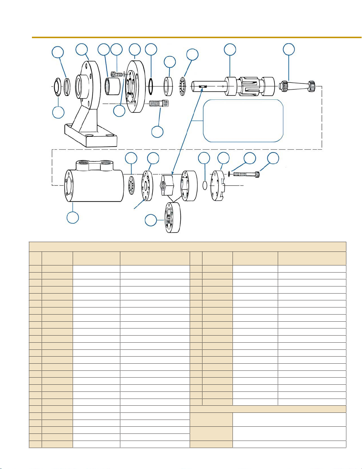
5
2
3
4
79
11
12
13
10
1
Small tapered holes
14
toward gerotor
HYDRAULIC MOTOR COMPONENT PARTS
Item
No.
10
11
12
12
12
12
12
12
12
12
12
PART
NUMBER
1
BSS-1
2
48CF
3
60CFM
4
52CFM
5
6
7
7
7
7
7
7
8
9
9
62B
50C
10CF
10CF-2-BOLT Oval Flange
10CF-4-BOLT Square Flange
10CF-T
10CF-ALUM
10CF-T-ALUM Turned Down Flange Aluminum
46CA
31C
31C-VITON
64CF
17CF
15CF
15CFM
15CF-1
15CFM-1
15CF-2
15CFM-2
15CFT
15CFMT
15CFMK
PART DESCRIPTION
Blood Slinger Shield
Dirt Seal All motors 13
Foot Mount FM style motors only 14
Shaft Bearing FM style motors only 14
Screw (10-32x1/2) All motors - 5 required 15
Copper Washer Seal All motors - 10 required 15
Round Flange Standard Flange 15
Turned Down Flange Ordering suffix x "-T" 17
Round Flange Aluminum 17
Screw (5/16-18x3/4) FM style motors only 19
Shaft Seal - Te? on
Shaft Seal - Viton Optional Seal 20
Thrust Race All motors 20
Thrust Bearing All motors - 2 required 20
Motor Shaft - Short F style motors only 20
Motor Shaft - Long FM & FMO style motors only 20
Motor Shaft - 1 Flat F style motors onlly 20
Motor Shaft - 1 Flat FM & FMO style motors only
Motor Shaft - 2 Flats F style motors onlly
Motor Shaft - 2 Flats FM & FMO style motors only
Motor Shaft - Tapped F style motors only
Motor Shaft - Tapped FM & FMO style motors only
Motor Shaft with Key FM&FMO only-3/16 x 1-1/4 Key
6
8
11
19
20
NOTE
Optional Seal - order separately
Ordering suffix "-2-BOLT"
Ordering suffix x "-4-BOLT"
Standard Seal 19
TIMING INSTRUCTIONS
Keyway & Lobe (with punch mark)
must be in line, only one of the four
lobes will give precise alignment.
Care and caution must be taken at
assembly.
15
It
e
No.
m
13
16
17
19
VITON-ASK-1
16
PART
NUMBER
13CA-1/4
13C
11CF
11CF-ALUM Motor Body
27CA-.125
27CD-.500
27CB-.745
14CF
39CF
39B-A
39CF-A
12C-.406
12C-.281
12C-.156
18C-1/4
18C-3/8
18C-1/2
18C-5/8
18C-1
18C-1-1/4
ASK-1
6
PART DESCRIPTION
Spline Drive
Spline Drive
Motor Body All motors except Aluminum
Gerotor Spacer A62 motors only
Gerotor Spacer A100 motors only
Gerotor Spacer A125 motors only
Gerotor cover All motors
Screw (10-32x1-1/4) A25, A37, A50 & A62 - 5 req.
Screw (10-32x1-3/4) A100 motors only - 5 required
Screw (10-32x2) A125 motors only - 5 required
Separator Plate A25 motors only
Separator Plate A37 motors ony
Separator Plate
Gerotor Assembly
Gerotor Assembly A37 motors only
Gerotor Assembly A50 motors only
Gerotor Assembly A62 motors only
Gerotor Assembly A100 motors only
Gerotor Assembly A125 motors only
Seal Kit includes (1) 31C, (1) 48CF, (10) 50C & (2)
17CF
Seal Kit includes (1) 31C-VITON, (1) 48CF, (10) 50C
& (2) 17CF
17
NOTE
A25 motors only
A37, A50, A62, A100, A125 only
Aluminum
A50, A62, A100, A125 motors only
A25 motors only
SEAL KITS
7
Page 18

FAX FEEDBACK SHEET
Our objective is to provide you the best products possible.
You may help us by providing feedback to us.
Please complete this survey and fax it back to us within 10 days.
Shipment No.:__________________
Shipment Date: _________________
Please circle your responses and FAX to (330) 659-6991
If you are RECEIVING or PURCHASING personnel, please answer the following:
Was this shipment received within the timeframe established by your company? YES NO
Did this shipment contain the correct items and quantity? YES NO
Was the box damage free? YES NO
Does the level of product quality meet your requirements and expectations? YES NO
Are you aware of our website?
If you are TECHNICAL personnel, please answer the following:
Did you need to contact our Technical Support staff? YES NO
If you did contact us, was our staff helpful and professional? YES NO
Did you use the installation, programming and/or hookup instructions? YES NO
Were the installation, programming and/or hookup instruction clear for you? YES NO
Completed By: ______________________________ Your Function: _____________________________
Company: _________________________________________
City, State, Zip: _________________________________
Phone: _________________________
Email: _________________________________
Thank you for helping us continually improve the products and services we provide you. For more detailed feedback, feel free to
contact our Customer Service Personnel at (330) 659-4187 ext.2300 or via email at
www.fawcettco.com YES NO
Fawcett Co., Inc. The Home of Mixed Flow Impellers
* Manufactured in the USA *
Page 19
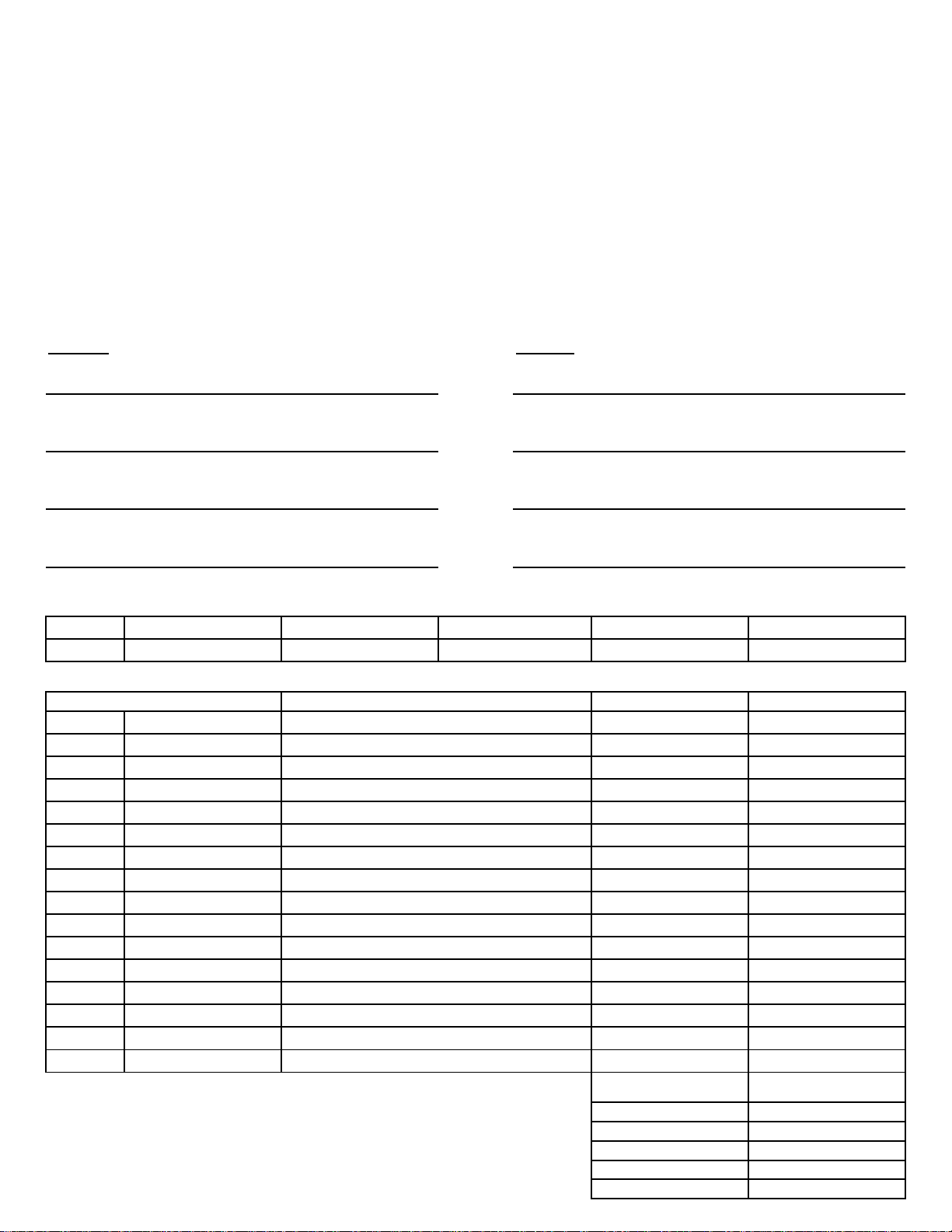
FAWCETT CO., INC.
PHONE: 330.659.4187
3863 Congress Pkwy. FAX: 330.659.6991
Richfield OH 44286 E-MAIL: [email protected]
ORDER FORM
Person Placing Order : ____________________________________ P.O. # : ______________________
Phone # : ________________________ FAX # : __________________________
SHIP TO:
Attention Attention
Location Location
Street Address Street Address
BILL TO:
City State Zip City State Zip
Req. Date
Quantity
Requesitioner
Ship Via
Buyer
F.O.B.
Richfield, OH
Item Description Unit Price Total
NET 30 Days
Terms
Sales tax will be added to deliveries in the state of Ohio
unless a tax exempt certificate is on file.
All orders are F.O.B. shipping point. Shipping charges
will be added to invoice.
Subtotal
Tax
Shipping
Miscellaneous
Balance Due
 Loading...