

Page 1
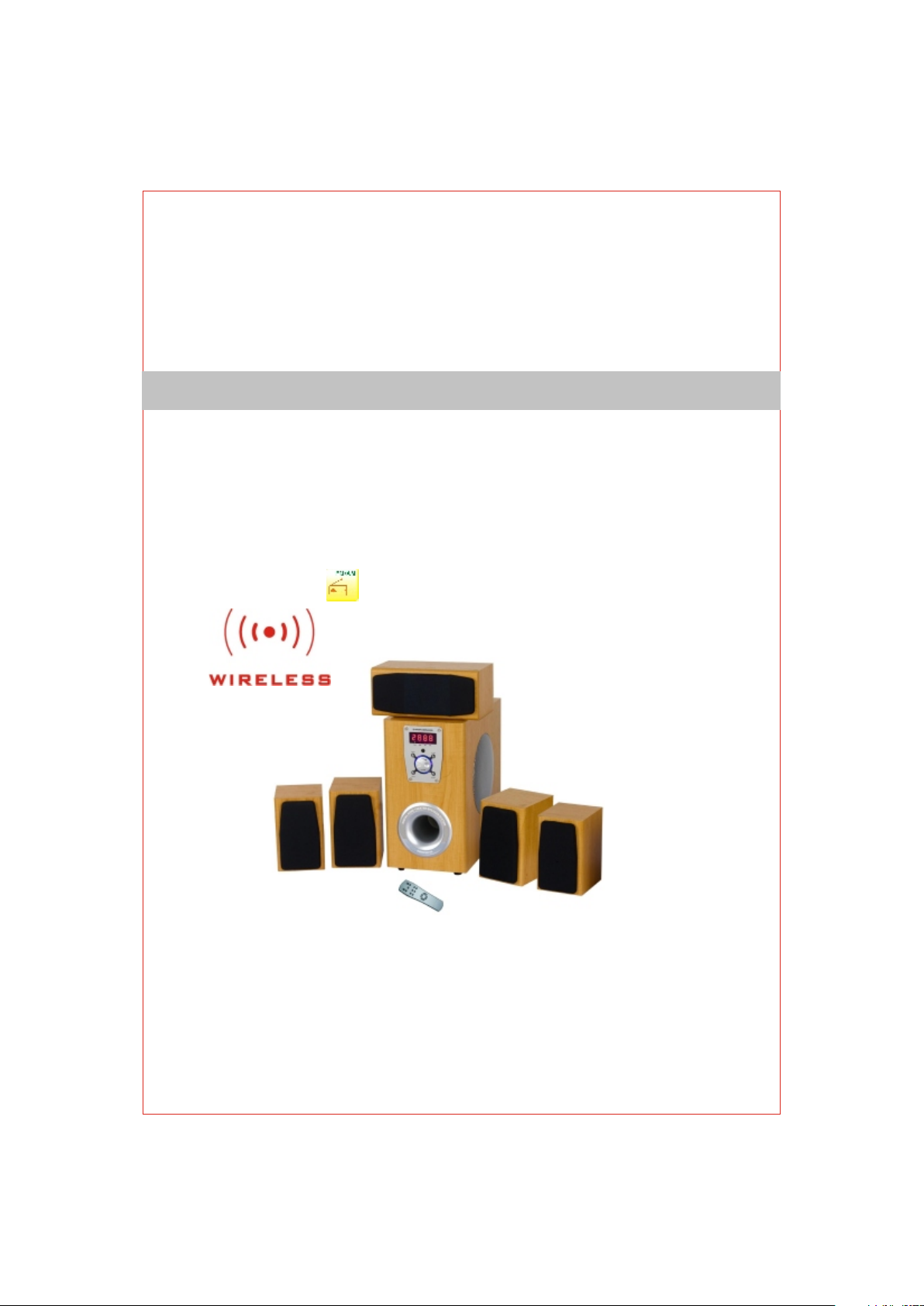
5 . 1 C H A C T I V E S U R R O U N D S P E A K E R5 . 1 C H A C T I V E S U R R O U N D S P E A K E R
AR5701WTAR5701WT
USER'S MANUALUSER'S MANUAL
Page 2
SAFTY INSTRUTIONS
CA UT IO N
To prevent el ectric shock do not use th is (polarized) plug wi th an extension cord,
receptacl e or other outlet unless t he blades can be fully ins erted to prevent blade
exposure.
WA RN IN G
TO REDUCE THE R ISK OF FIRE O R ELECTRIC SH OCK, DO NOT EXPOSE
THIS APPLIA NCE TO RAIN OR MOISTURE.
IMPORTANT SAFEGUARDS
1-READ INST RUCTIONS --- All the saf ety and operating inst ructions should be
read before t he appliance is operat ed.
2-RETAIN IN STRUCTIONS --- The ope rating instruction s should be retained for
future refe rence.
3- HEED WARNI NG --- All warnings on the a ppliance and in the oper ating
instructi ons should be adhered to .
4- FOLLOW INS TRUCTIONS --- All oper ating and use instruct ions should be
followed.
5- WATER AND MO ISTURE -- - The applian ce should not be used near w ater - for
example, ne ar a bathtub, washbowl , kitchen sink, laundr y tub, in a wet basement, or
near a swimmi ng pool, etc.
6- OUTDOOR US E --- Warni ng: To reduce t he risk of fire or electri c shock, do not
expose this a ppliance to rain or mois ture.
7- LOCATION : The appliance should b e installed in a stable lo cation.
8- VENTILAT ION --- The appliance sh ould be situated so that i ts location or positio n
does not inte rfere with its proper ve ntilation. For examp le, the appliance shou ld not
be situated o n a bed, sofa, rug, or simil ar surface that may bloc k the ventilation
openings; o r placed in a built-in ins tallation, such as a clo sed bookcase or cabine t
that may impe de the flow o f air through t he ventilation openi ngs.
9- HEAT --- The a ppliance should be sit uated away from heat sou rces such as
radiators , heat registers, stov es, or other appliance s (including amplifi ers) that
produce hea t.
10- POWER SOU RCES --- Th e appliance s hould be connected to a po wer supply
only of the typ e described in the opera ting instructions or a s marked on the
appliance .
1
Page 3

Page 4
2- Cleaning t he unit
Disconnec t the mains plug from the ou tlet before attempti ng to clean the unit.
Don not use har sh abrasives or chemic als to clean it, as it will da mage the surface
finish.
Use only a soft a nd damp cloth.
3- Accessor ies
Please use th e accessories enclos ed in the unit. Damage cau sed by using
non-recom mended or non-provid ed accessories would n ot be warrant ed.
4 - Placement :
Do not use this u nit near water.
Do not allow an ything to drop into the su bwoofer case through i ts ventilator, as it
could resul t in fatal electric shoc k or file.
Place the uni t far enough from other eq uipments from good hea t dissipation.
Place the uni t on a stable surface and ou t of reach of children to av oid damage to
the unit or the r isk of injury to people.
5- Maintena nce
To avoid shoc k hazard or damage to the un it, do not attempt to remo ve the cover
or the real pan el. All servicing shou ld be referred to qualif ied service personne l.
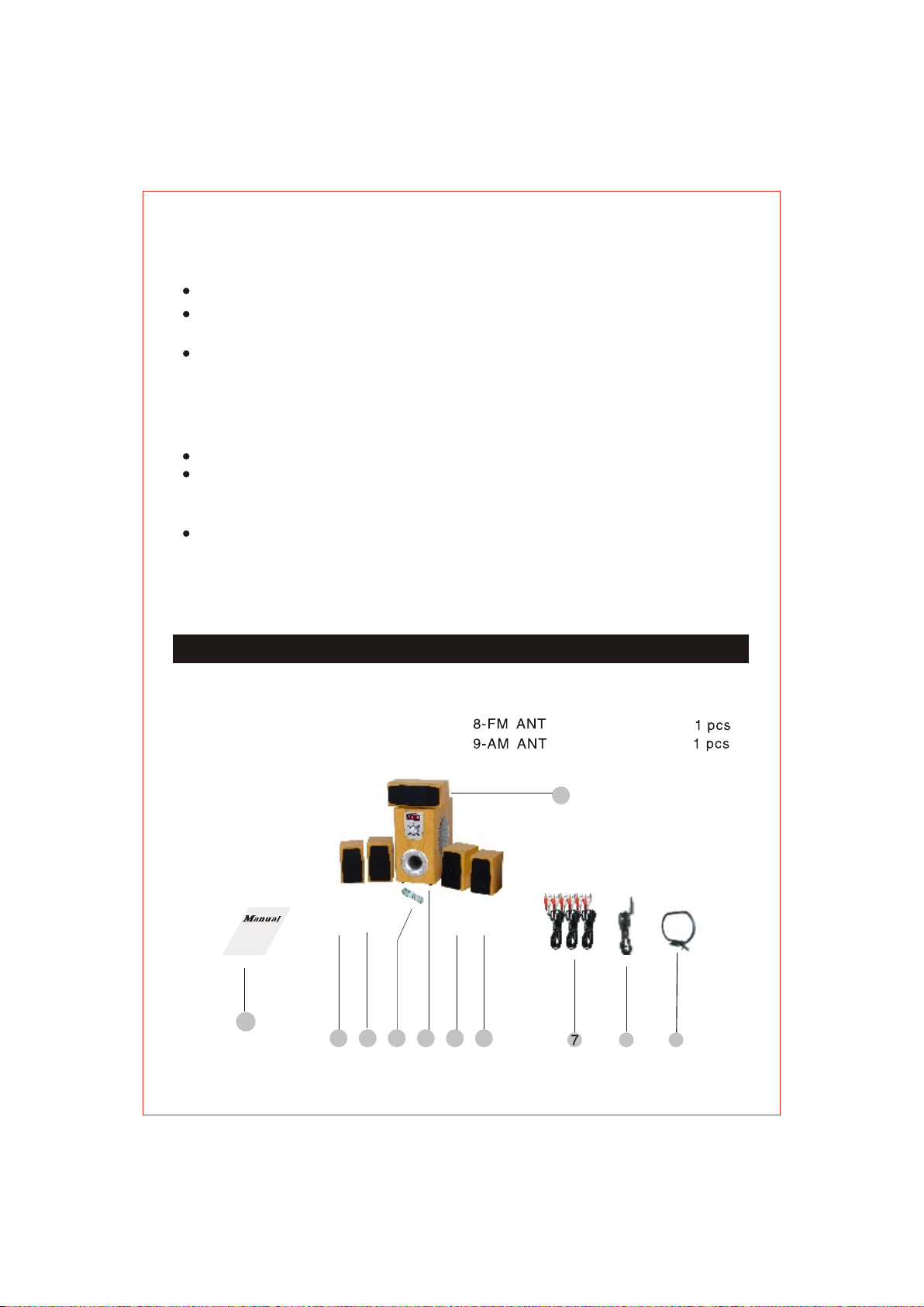
PACKING LIST
1-User's Ma nual 1 pcs
2-Remote Co ntrol 1 p cs
3-Subwoof er Speaker 1 pcs
4-Center Sp eaker 1 pcs
5- Front Spea ker 2 pcs
1
2
6- Surround S peaker 2 pcs
7 CABLE RCA 3 pcs-
55
36 6
3
4
8 9
Page 5
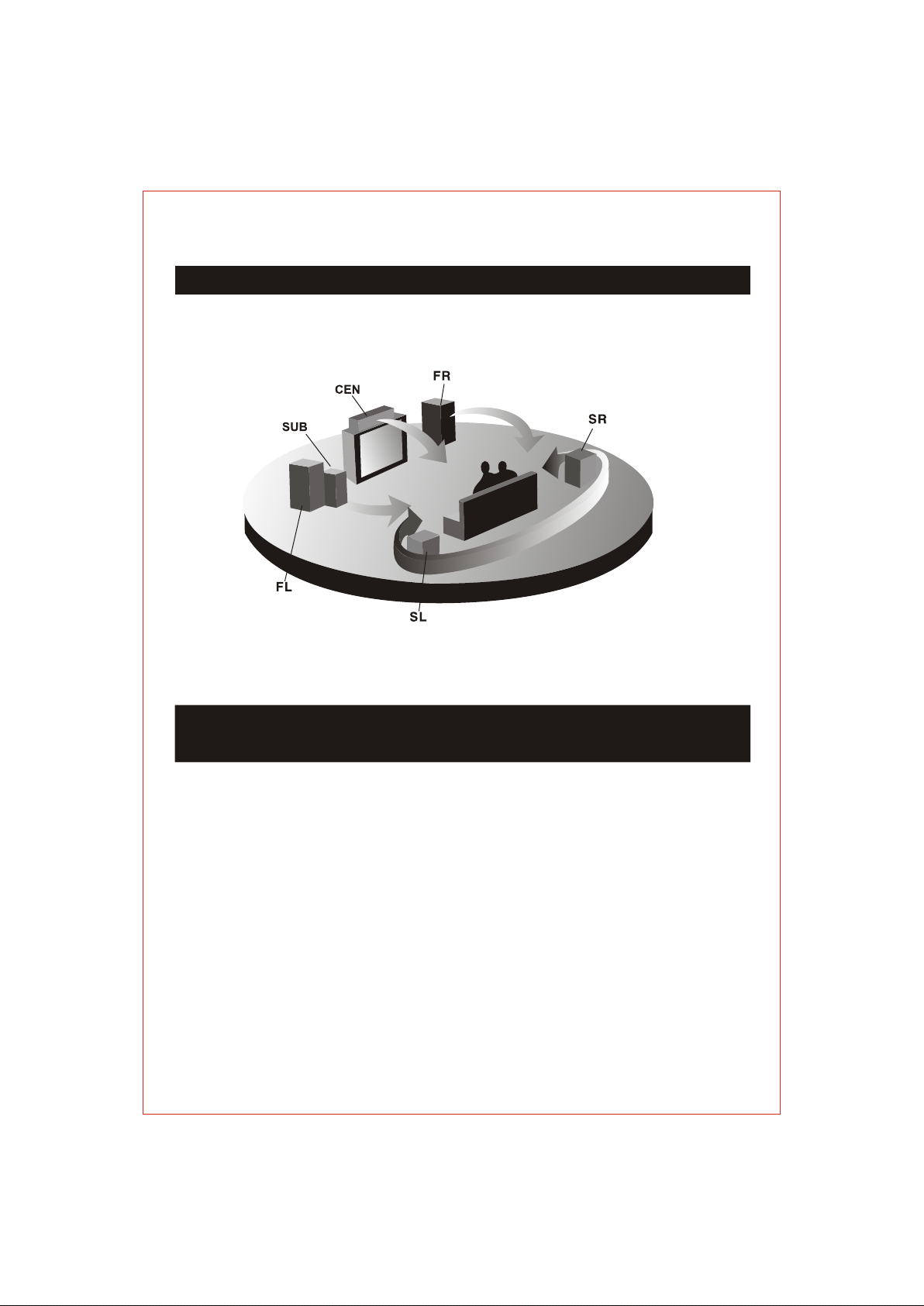
PLACEMENT OF THE SPEAKERS
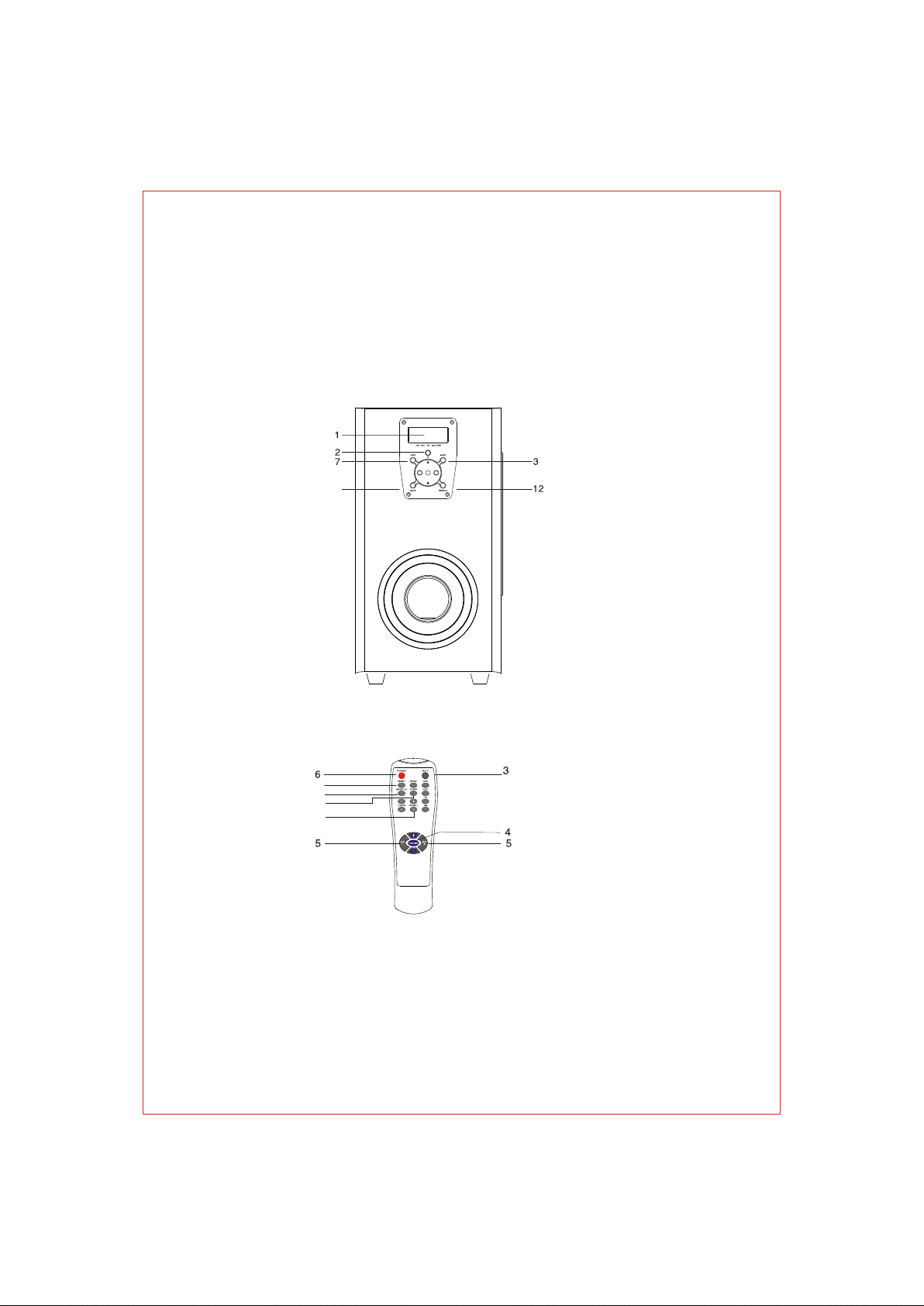
DESCRIPTION OF THE FRONT PANEL OF SUBWOOFER
AND REMOTE CONTROL
1- LED
2- IR:Wirel ess accept
3- MUTE: Cont rols the stand by of the sys tem
4- VOL + / VOL-: To i ncrease / decrease the m aster volume of the spea ker
5- SUB + / SUB -: To in crease / decrease the vo lume of the subwoofer
6- STANDBY:Controls the standby or play state of the system
7- INPUT SELECT:To switch the input mode DVD,AUX,FM,AM of the speak
System
8- SCAN :To scan the tuner by manually or automatically
9- RESET:To set the volume of all channels into initialization
+
4
system
Page 6
10
- PRESET+/PRESET-:Read out the saved datas of tuner
11
- ST/MO:To switch the output mode of tuner between FM stereo and
12
- SAVE/CLEAR:To save/clear the datas of the tuner
8
single track
9
12
11
10
5
Page 7
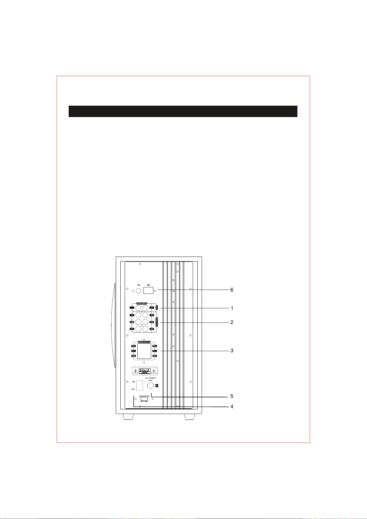
DESCRIPTION OF THE REAL PANEL OF THE SUBWOOFER
1-AUS ( L / R)
To rece ive the s ignal from PC, CD,M P3, Tap e Player, et c.
2-INP UT (5.1 CH)
(1)FL / F R: Fron t Left / Right channe l input c onnector s of the sy stem.
(2)CE N: Cent er channel input co nnect or.
(3)SU B: Subw oofer Channel inp ut conn ector.
(4)SL / S R: Surr ound Left / Right cha nnel in put connec tors of t he system.
3-OUT PUT (5. 1CH)
(1)FL / F R: Fron t Left / Right channe l outpu t connecto rs of the s ystem
(2)CE N: Cent er channel output c onnec tors.
4-POW ER ON/O FF
Switc h for tur n on/off the power
5-AC IN : AC powe r cord.
6-THE WIRELESS INPUT OF FM/AM
6
Page 8
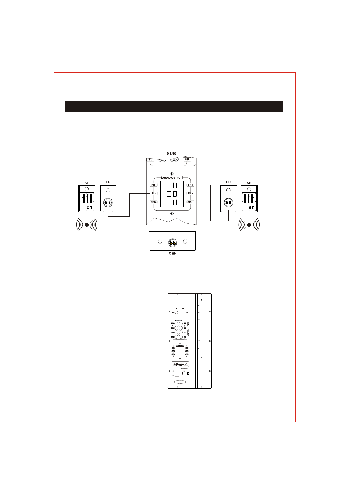
CONNECTIONS ILLUSTRATION:
To preven t malfu nction and/or da mage to s peakers or other d evices, always t urn
down the vo lume, a nd turn off the powe r on all de vices before mak ing any
connect ions.
< Connect ions of t he Subwoofer, th e Cente r, the Front Speak ers >
< Connections of the sub woofer an d the audio source >
1. To PC, CD, MP3 ,Tape Play er or any aud io device offering a LIN E-OUT aud io
connection.
2. To DVD
To PC, CD, M P3, T ape Playe r ,et c.
To DVD(5 .1C H)
7
Page 9
OPERATION
1-Press dow n the tip of the PO WER rocker sw itch with a whi te "I"on the back of the
subwoofer t o turn on the sys tem. The syst em is then turn ed on and the
indicator l ight on the Dig ital Volume D isplay of the f ront panel wi ll turn red.
2-Press the M UTE button on t he remote con trol or the fro nt panel of the subwoofer
once, and the s ystem will be s witched to MU TE mode.
3-Press the f ollowing bu ttons on the fr ont panel of th e subwoofer o r remote control
to a suitable l istening le vel.
(1) MAST + (VOL + ) / MAST- (VOL -) : to adjust the v olume level o f the system
(2) Press the S UB+ and VOL+ to a djust or SUB- a nd VOL- to incr ease or
decrease th e volume leve l of the subwoo fer.
4-Press the M UTE button on t he remote con trol once to tu rn off the volume of the
system, and t he mute indic ator light on t he front pane l of the subwoofer will turn
off. Press th e MUTE button a gain and the mu te indicato r light will tu rn on.
* It is recomme nded that the P OWER rocker s witch on the ba ck of the subwoofer
be turned off a nd that the AC po wer cord be unp lugged from t he supply whe n the
system is lef t unused for a lo ng period of ti me.
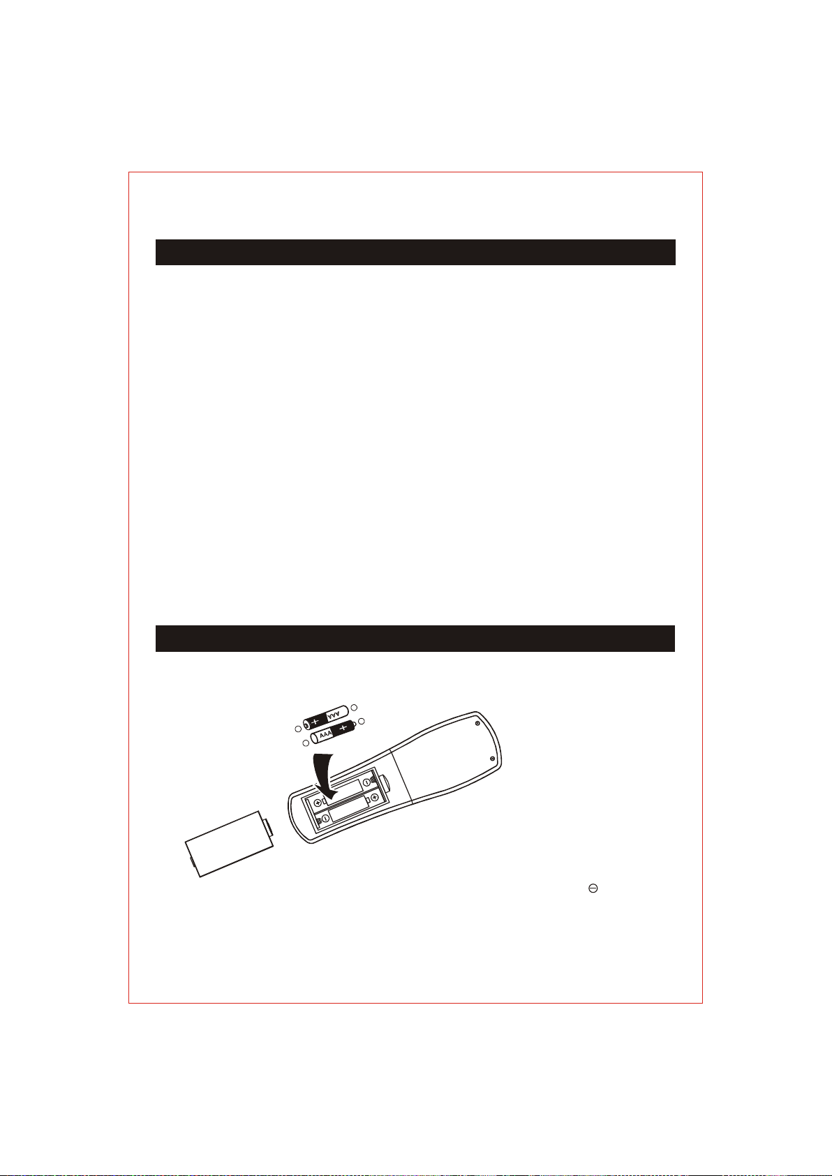
BATTERY INSTALLATION:
_
+
_
+
Remember:The spring touches the" "
side of each battery.
8
Page 10

IMPORTANT NOTES
< AC POWER >
* Make sure tha t the power supply is corr ect and never handle the p ower cord or its
plug with wet h ands when plugging int o, or unplugging from, a nd outlet.
* Ensure that t he main power switch is in t he OFF position before c onnecting the AC
power cord to t he power supply to avoid d amage to the system.
* A damaged pow er cord can easily cause a n electric shock or fire h azard. Never use
a power cord af ter it has been damaged.
SPECIFICATIONS
POWER INPUT ................... AC 127 /220V 60H z
TOTAL SYSTEM POWER .....200 Watts ( 50W + 30Wx 5 )
FREQUENCY RESPONSE ...35 Hz~2 0 KHz
S / N RATIO ........................ > = 70dB
DISTORTION ..................... 0.1% @ 1W
DRIVER UNIT .....................S UB: 6.5" 8 Ohms; SAT 3" 4 Ohms
SEPARATION ..................... >= 40dB (1KH z)
FUNCTION ..........................MUTE, M ODE, SUB+ /-, VOL+/-, REMOTE CONTROL
&WIRELESS & AM/FM TUNER
DIMENSION (MM) ...............SUB: 175W x332H x 3 30D CEN:3 00W x128H x 110D
SAT: 105W x 173H x 147D
Note:Subject specifications to modifications without previous warning.
REAR: 120W x 198H x 110D
9
Page 11

CONTENTS
SAFETY INSTRUTIONS ..... ..... ..... ..... ..... ..... ..... ..... ..... ..... ..... ..... ..... ..... ..... ..... ..... ..... ....1
IMPORTANT SAFEGUARDS ... ..... ..... ..... ..... ..... ..... ..... ..... ..... ..... ..... ..... ..... ..... ..... ..... ..... 1
IMPORTANT SAFETY INSTRUC TIONS . ..... ..... ..... ..... ..... ..... ..... ..... ..... ..... ..... ..... ..... ..... ..2
PACKING LIST ........... ..... ..... ..... ..... ..... ..... ..... ..... ..... ..... ..... ..... ..... ..... ..... ..... ..... ..... ..... ..3
PLACEMENT OF THE SPEAKERS .. ..... ..... ..... ..... ..... ..... ..... ..... ..... ..... ..... ..... ..... ..... ..... ....4
DESCRIPTION OF THE FRONT PAN EL OF SUBWOO FER & REM OTE CON TROL .. ..........4
DESCRIPTION OF THE REAL PANEL OF THE SUBW OOFER . ..... ..... ..... ..... ..... ..... ..... ..... .6
CONNECTIONS ILLUSTRATI ON .... ..... ..... ..... ..... ..... ..... ..... ..... ..... ..... ..... ..... ..... ..... ..... ....7
OPERATION ................. ..... ..... ..... ..... ..... ..... ..... ..... ..... ..... ..... ..... ..... ..... ..... ..... ..... ..... ..... 8
BATTERY INSTALLATION ... ..... ..... ..... ..... ..... ..... ..... ..... ..... ..... ..... ..... ..... ..... ..... ..... ..... ....8
IMPORTANT NOTES ............. ..... ..... ..... ..... ..... ..... ..... ..... ..... ..... ..... ..... ..... ..... ..... ..... ..... ..9
SPECIFICATIONS ....... ..... ..... ..... ..... ..... ..... ..... ..... ..... ..... ..... ..... ..... ..... ..... ..... ..... ..... ..... ..9
10
 Loading...