

Page 1

User’s Manual v1.0.0.0
F740
A/2013
www.favite.com
Copyright○C2013, Favite, Inc
Page 2

[鍵入文字]
Federal Communication Commission Interference Statement
This device complies with Part 15 of the FCC Rules. Operation is subject to
the following two conditions:
(1) This device may not cause harmful interference, and (2) this device must accept
any interference received,including interference that may cause undesired operation.
This equipment has been tested and found to comply with the limits for a Class A
digital device, pursuant to Part 15 of the FCC Rules. These limits are designed to
provide reasonable protection against harmful interference in a residential installation.
This equipment generates, uses and can radiate radiofrequency energy and, if not
installed and used in accordance with the instructions, may cause harmful interference
to radio communications. However, there is no guarantee that interference will not
occur in a particular installation. If this equipment does cause harmful interference to
radio or television reception, which can be determined by turning the equipment off
and on, the user is encouraged to try to correct the interference by one of the
following measures:
- Reorient or relocate the receiving antenna.
- Increase the separation between the equipment and receiver.
- Connect the equipment into an outlet on a circuit different from that
to which the receiver is connected.
- Consult the dealer or an experienced radio/TV technician for help.
FCC Caution: Any changes or modifications not expressly approved by the party
responsible for compliance could void the user's authority to operate this
equipment.This transmitter must not be co-located or operating in conjunction with
anyother antenna or transmitter.
Radiation Exposure Statement:
This equipment complies with FCC radiation exposure limits set forth for an
uncontrolled environment. This equipment should be installed and operated
with minimum distance 22cm between the radiator & your body.
Professional installation instruction
1. Installation personal
This product is designed for specific application and needs to be installed by a
qualified personal who has RF and related rule knowledge. The general user shall
not attempt to install or change thesetting.
2. Installation location
2
v2.2.1.0, Copyright○C2013, Favite, Inc
Page 3

[鍵入文字]
The product shall be installed at a location where the radiating antenna can be kept
22cm from nearby person in normal operation condition to meet regulatory RF
exposure requirement.
3. External antenna
Use only the antennas which have been approved by the applicant. The
non-approved antenna(s) may produce unwanted spurious or excessive RF
transmitting power which may lead to the violation of FCC limit and is prohibited.
4. Installation procedure
Please refer to user’s manual for the detail.
5. Warning
Please carefully select the installation position and make sure that the final output
power does not exceed the limit set force in relevant rules.
The violation of the rule could lead to serious federal penalty.
3
v2.2.1.0, Copyright○C2013, Favite, Inc
Page 4

F740 User Guide
Table of Contents
1. Introduction ........................................................................................................... 1
1.1 Overview .......................................................................................................... 1
1.2 Requirement...................................................................................................... 1
1.3 Reference Documents ....................................................................................... 2
1.4 Specifications.................................................................................................... 3
2. Reader Hardware Installation and Operation ........................................................ 8
2.1 Receiving the RFID Reader .............................................................................. 8
2.2 Diagnostic LEDs............................................................................................. 10
2.3 Antenna Panel ................................................................................................. 12
2.4 Demonstration Software Guide ...................................................................... 12
Figures
Figure 1: F740 Reader Physical Size
Figure 2: F740 Reader I/O Terminal
Figure 3:
Antenna Port Terminal Interface
Figure 4: F740 GPIO Pin definition and I/O description
Figure 5: F740 (1)
Figure 6: F740 (2)
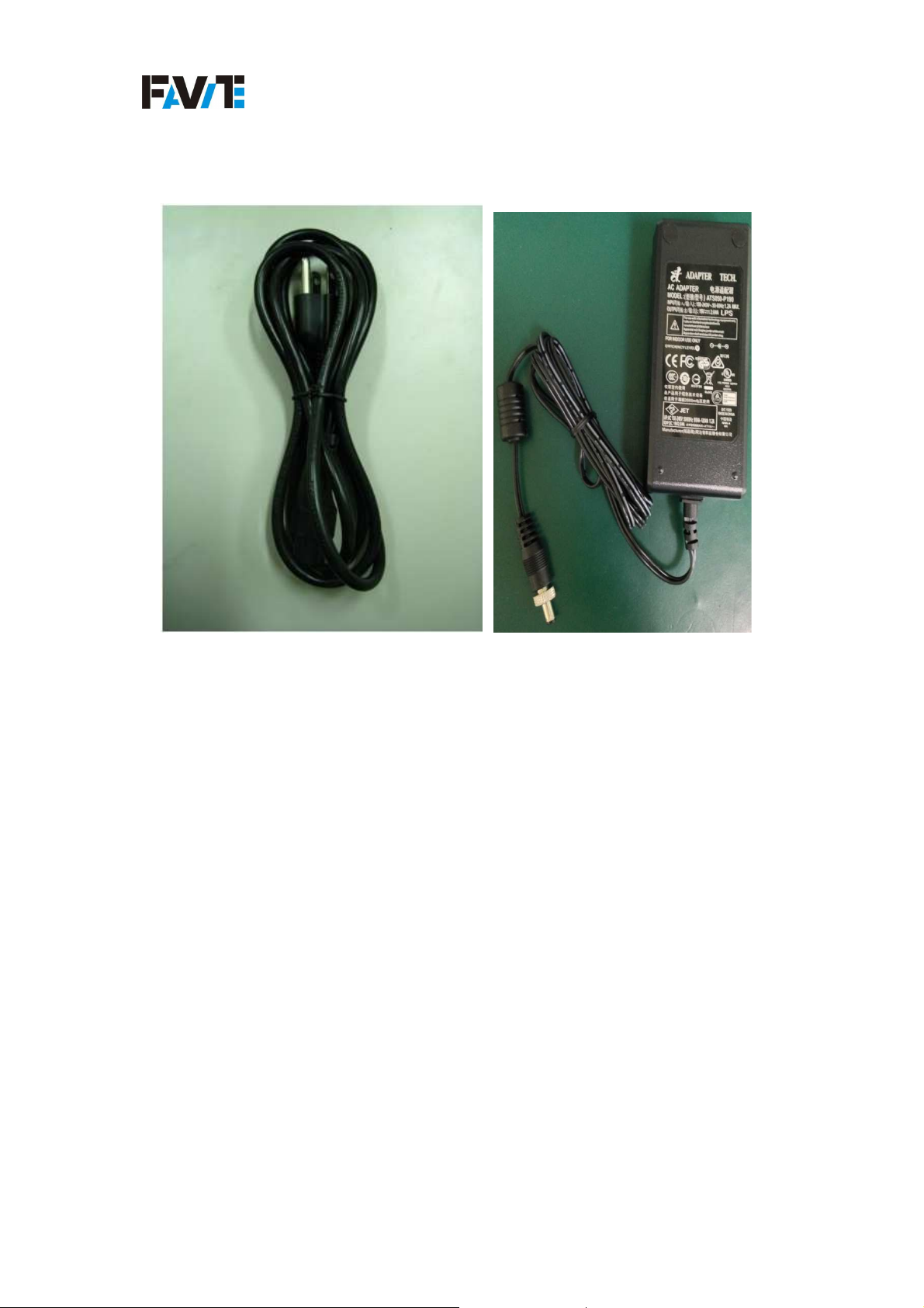
Figure 7: F740 Power Supply and Adapter cable
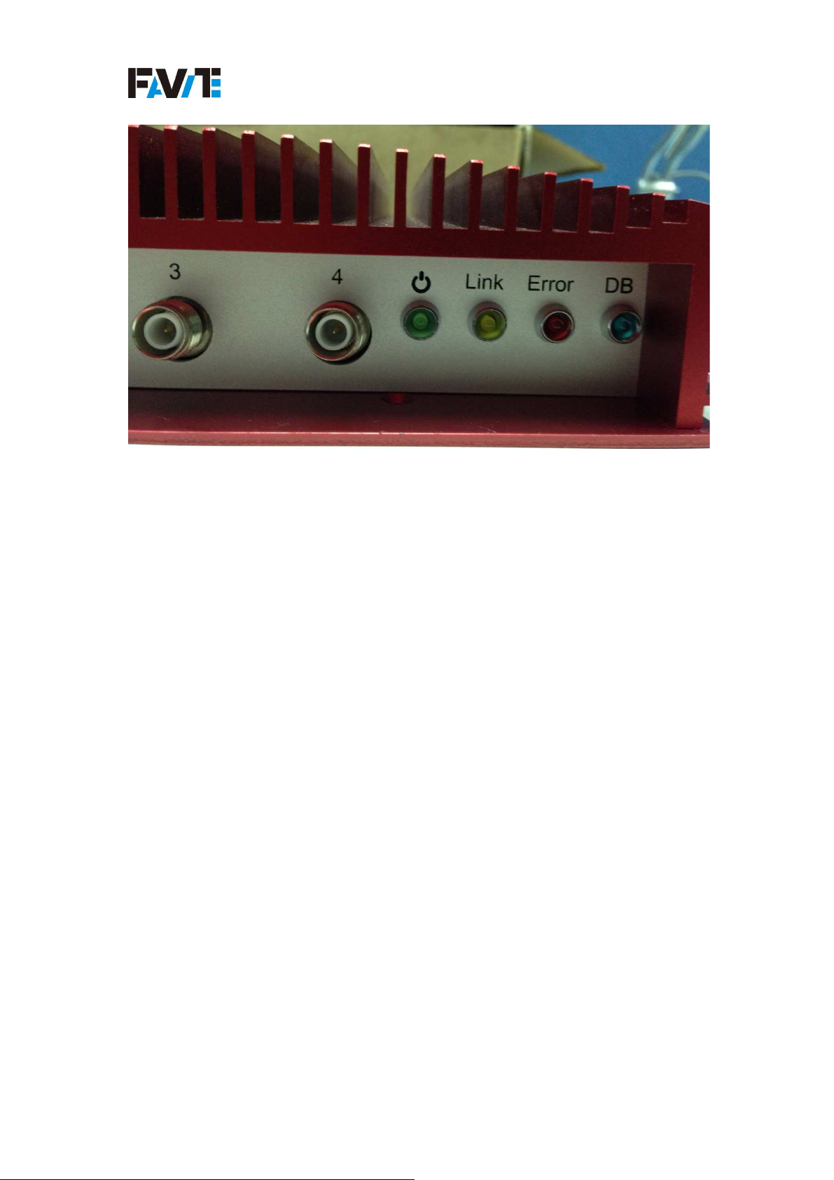
Figure 8: F740 Reader Diagnostic LEDs
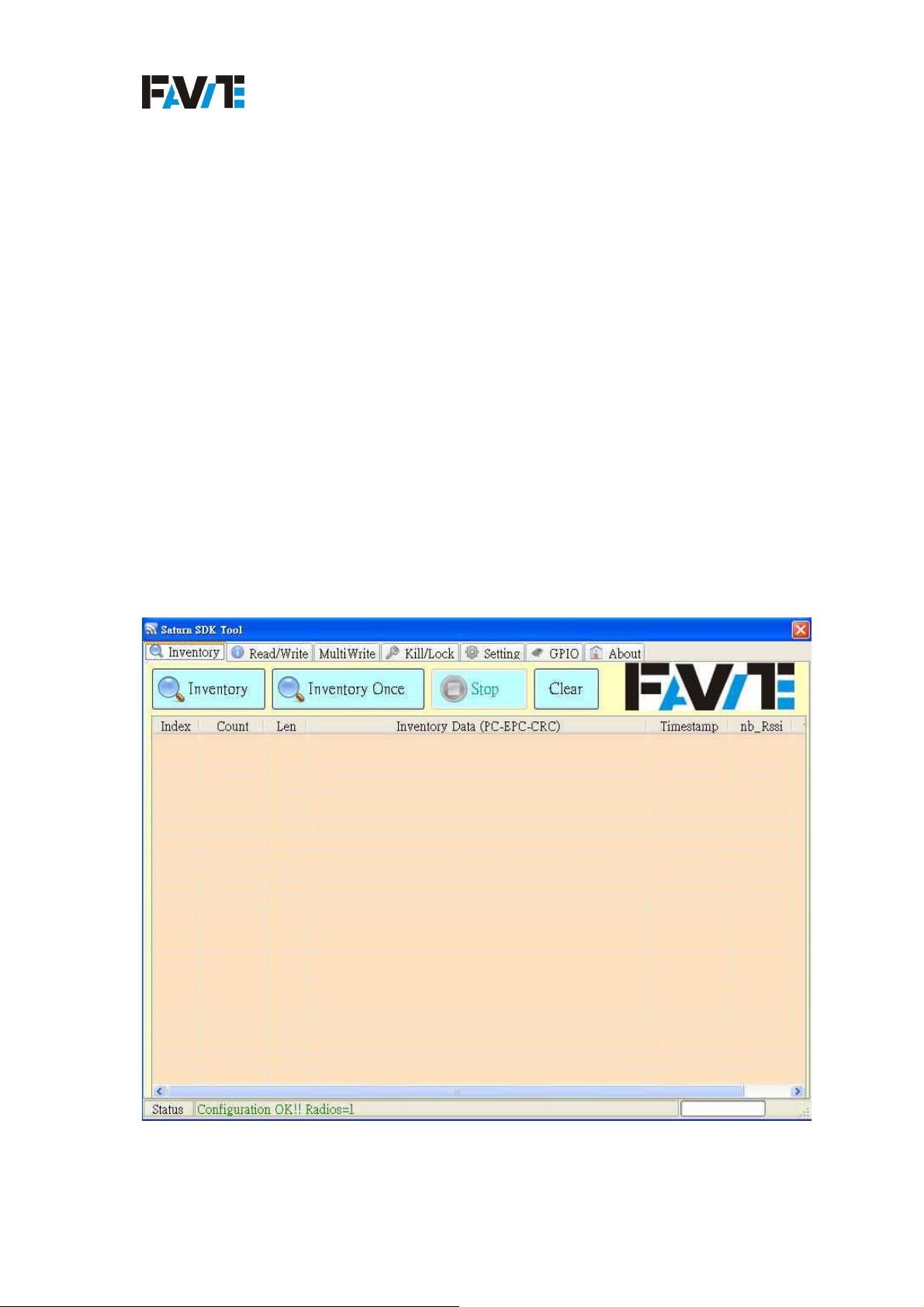
Figure 9: Demo Program
i
v2.2.1.0, Copyright○C2013, Favite, Inc
Page 5

F740 User Guide
Tables
Table 1: Reference Documents ...................................................................................... 2
Table 2: Specification of the F740 ................................................................................. 3
ii
v2.2.1.0, Copyright○C2013, Favite, Inc
Page 6

F740 User Guide
1. Introduction
This user’s manual guide is providing instruction for installing and operating the F740
RFID reader.
This document is designed for use by RFID system integrators and software developer
who develops relatively program and extended systems that take full advantage of the
RFID Reader's capabilities.
1.1 Overview
F740, one of FAVITE RFID reader family, is an Intel ATOM CPU based smart
reader. The F740 is embedded with Impinj R2000 chip and following EPC Class1
Gen2 Dense Reader mode (DRM) / ISO 18000-6C. The F740 is equipped with 4 TNC
RF antenna ports which could support 4 mono-static antennas that could support to
the richest enterprise applications. With the powerful combination of TI ARM9 and
1GB memory, the F740 is the smartest RFID reader available and capable of running
complex RFID applications.
The RFID Reader is delivered with the following components and accessories:
One (1) RFID Reader.
One (1) power supply and cord.
Operation system:
A. Linux embedded operation system with SCO server.
1.2 Requirement
The list following is the requirements of environment of the FS-GF801:
Standard DC 19V +/ - 0.5V
2.6A Power supply
Favite demo software/ the software developed based on Favite Software
Development Kit
1
v2.2.1.0, Copyright○C2013, Favite, Inc
Page 7
F740 User Guide
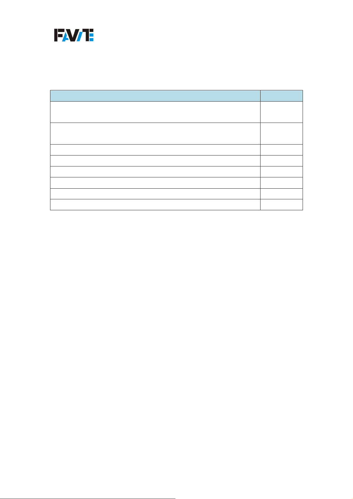
1.3 Reference Documents
Table 1: Reference Documents
Reference Document Version
EPC Class-1 Gen-2 UHF RFID Protocol for communications at
850-960MHz
FAVITE FS-GF801 GPIO Programming Guide DotNet CSharp
2.0.0.0
(optional)
FAVITE SDK Getting Started Guide CSharp WinCE (optional) 2.0.1.0
FAVITE Saturn 7 AP User Guide (optional) 2.2.0.0
FAVITE FS-GF801Recover Guide (optional) 1.0.0.1
FAVITE SCO Protocol User Guide 1.1.1.0
FAVITE Scorpio Tool User Guide 1.1.1.0
FAVITE SCO Recovery User Guide 1.1.1.0
2
v2.2.1.0, Copyright○C2013, Favite, Inc
Page 8
F740 User Guide
NCC
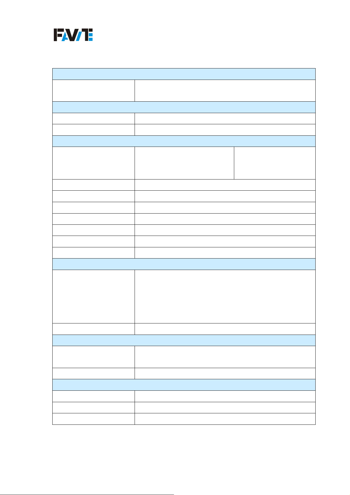
1.4 Specifications
Table 2: Specification of the F740System
Chipset
PHY: Impinj R2000
MAC: ATMEL AT91SAM7S-256
Protocol
RFID Protocol Support EPC Gen 2 , ISO 18000-6C
Support EPC DRM Yes (with DRM Filter) Switchable
RF
Frequency
US: 902 ~ 928MHz(FHSS)
EU: 865 ~ 868MHz
SRRC: 920~925MHz
JP:952~954MHz
: 922-928MHz
Demodulation ASK or PSK
Modulation Depth 90% nominal
Data Encoding FM0 or Miller code
Bit Rate Supports uplink data rates of up to 640 Kbps (DRM)
TX Output power 5 ~ 32dBm in 0.1dB step
Antenna Type 4Port Mono-static
Antenna connector 4 Reverse Polarity TNC connectors
Regulatory and Environmental Compliance
FCC 47 CFG Ch.1 Part 15 (US)
ETSI EN 302 208-1 (V1.1.1) (EU)
EMC certification
NCC CAAI10LP0970(TW)
SRRC SRTC2010-A070-0016 (China)
DSP RJ9905 10C02 (JP)
Safety Certification CE/FCC Class A, UL, CCC
Environment
Temperature Range
Operating: 0 ~ 55 degree C @ 80%RH
Storage: -20 ~ 85 degree C @ 90%RH
Humidity 10% ~ 85% Non-condensing
System Architecture
Processor TI ARM9
System Memory 1GB DDR2 SDRAM
Internal Storage 1GB Flash
3
v2.2.1.0, Copyright○C2013, Favite, Inc
Page 9
F740 User Guide
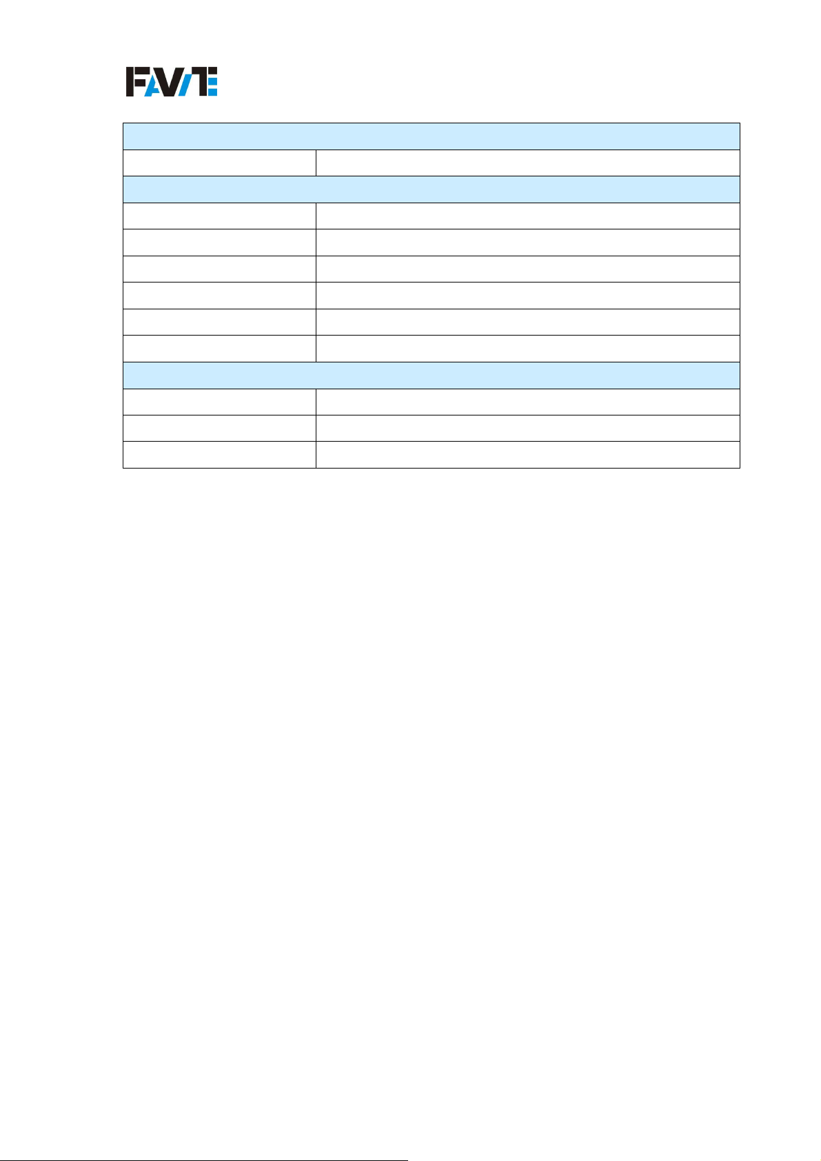
Software
Operation System Linux with SCO server
General Characteristics
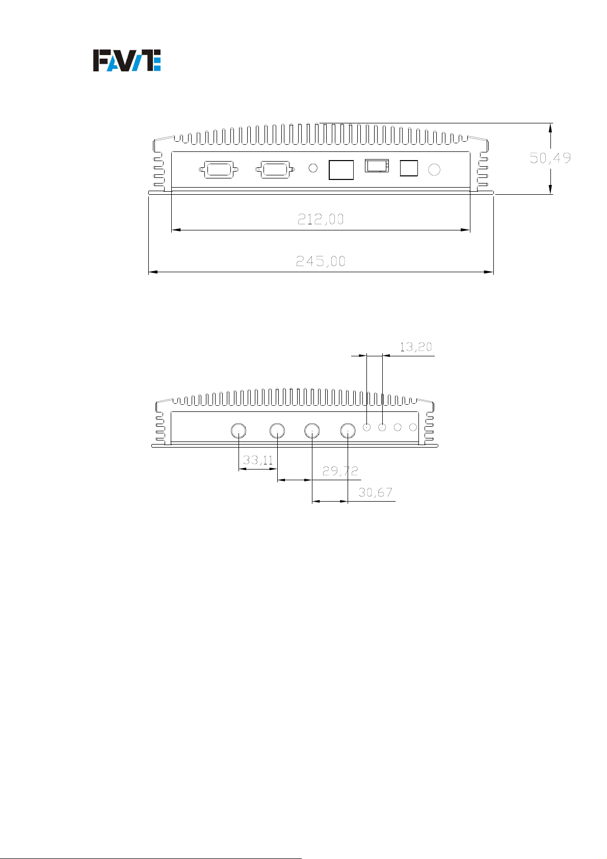
Dimension 500mm x 245 mm x 50.49mm
Weight 2.5 Kg
Base Material Die-cast aluminum
Mounting Wall mounting, vertical placement
Power Input DC 19V +- 0.5V / 1.5A @ 33dBm
Power Consumption 28.5 W (Typical)
Communication
USB USB2.0
Ethernet 10/100 Base-T (RJ-45)
GPIO 4 digital input, 4 digital output
4
v2.2.1.0, Copyright○C2013, Favite, Inc
Page 10
F740 User Guide
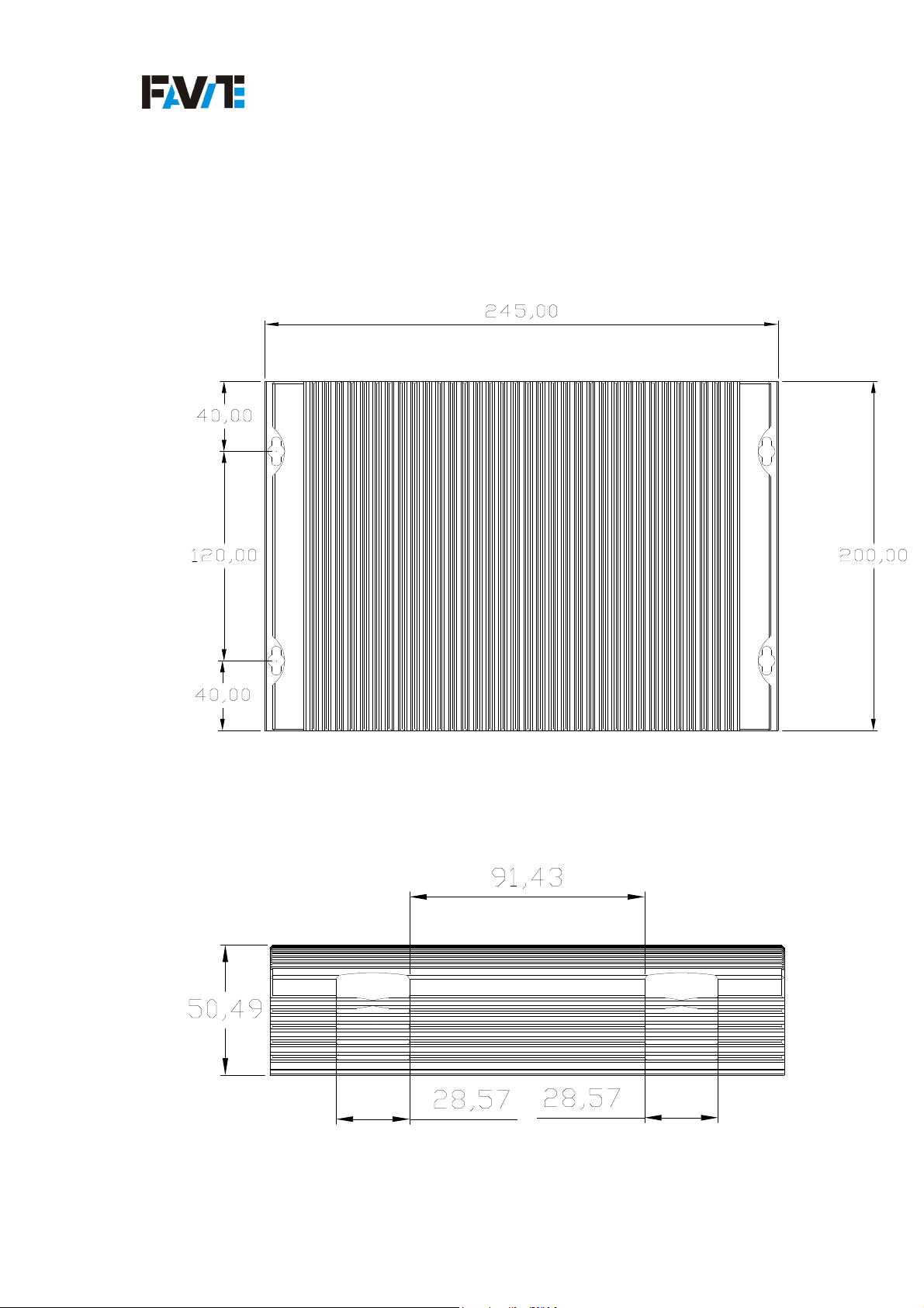
MMMMechanical: Reader Physical Size
echanical: Reader Physical Size
echanical: Reader Physical Sizeechanical: Reader Physical Size
Figure 1: F740 Reader Physical Size
5
v2.2.1.0, Copyright○C2013, Favite, Inc
Page 11
F740 User Guide
6
v2.2.1.0, Copyright○C2013, Favite, Inc
Page 12
F740 User Guide
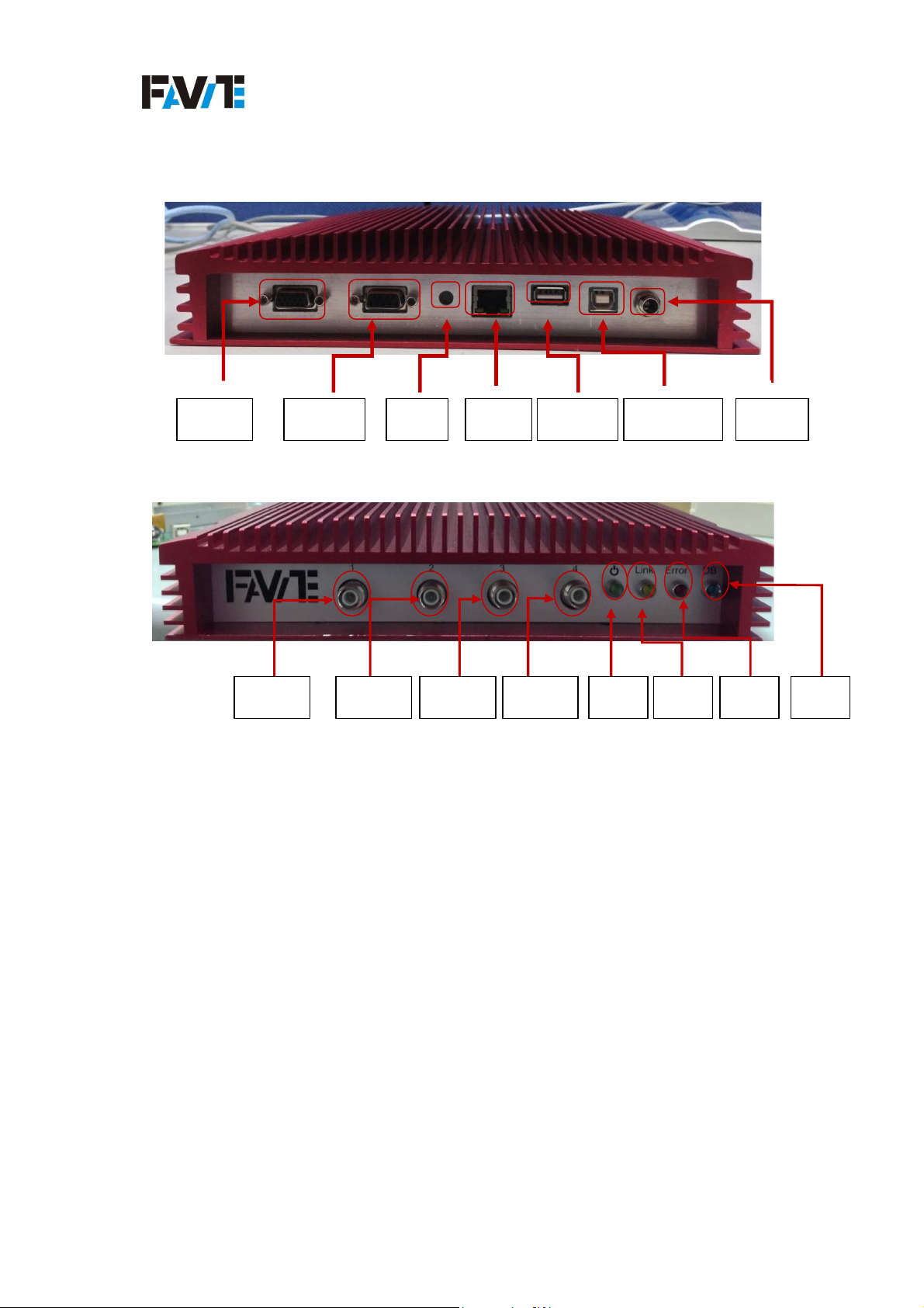
Figure 2: F740 Reader I/O Terminal
GPIO RS232 reset RJ45
Figure 3:
Antenna1 Antenna2 Antenna3 Antenna4 power link error debug
Antenna Port Terminal Interface
USB2.0
FTDI com port
power
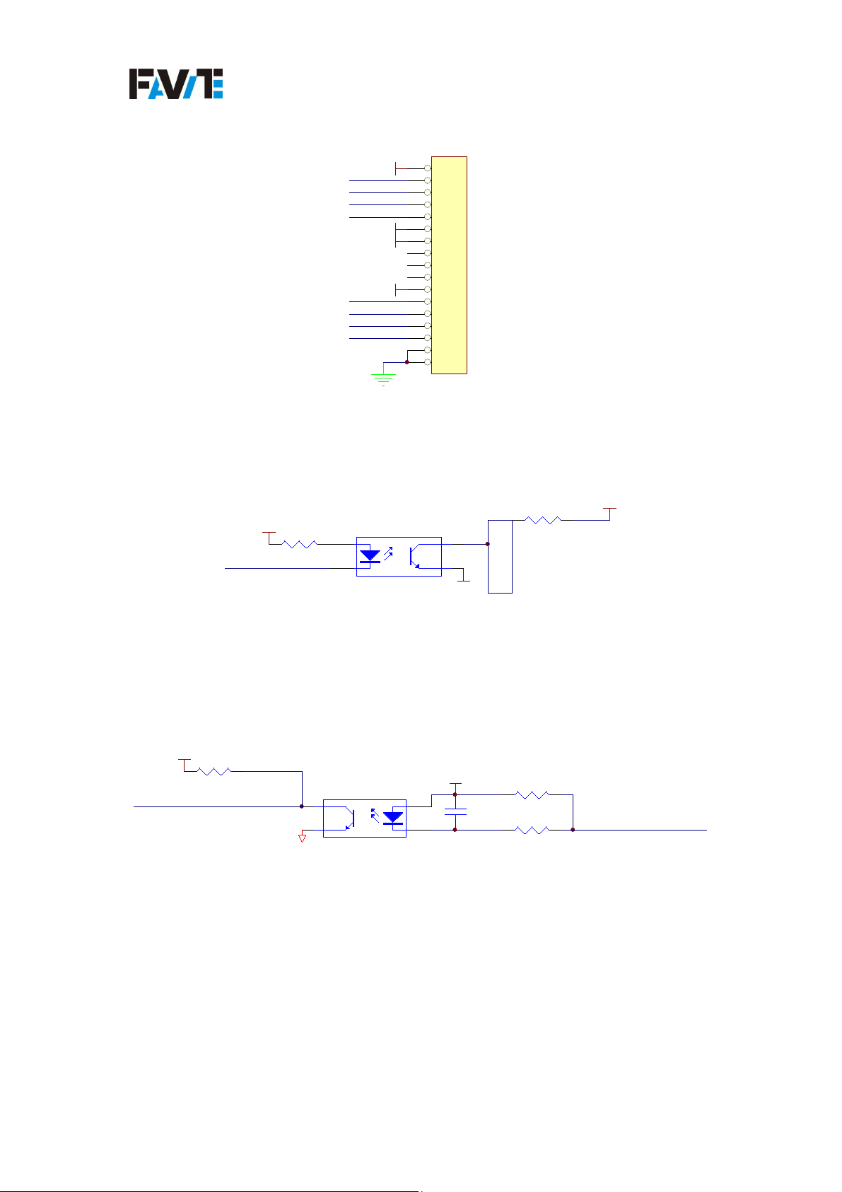
Figure 4: F740 GPIO Pin definition and I/O description.
Pin definition
Pin definition
Pin definitionPin definition
7
v2.2.1.0, Copyright○C2013, Favite, Inc
Page 13
F740 User Guide
D-SUB 15pin
V1 1
GPIO_O1
GPIO_O2
GPIO_I1
GPIO_I2
GND-1
GND-2
GPIO_O3
GPIO_O4
GPIO_I3
GPIO_I4
V2
2
3
4
5
6
7
8
9
10
11
12
13
14
15
16
17
GPIO
GPIO-OUT Circuit diagram (add figure#)
VDD3.3VGP
Note:
R96
4K7/4
GPIO_IN4
VDD3.3VGP
R94
4K7/4
GPIO_OUT4
R95
U13
1
2
UPC817
4
3
GND-2
47K/6
GPIO-IN Circuit diagram(add figure#)
GND
4
3
U14
UPC817
V2
1
2
C68
0.1uF/4
R98
47K/6
R99
10K/6
GPIO_O4
V2
GPIO_I4
Please add the 4k7 electric resistances. The limitation of voltage is from 12V to 24V.
The limitation of Watt is above 5W.
If FS-GF801 is going to transmit signal to other device, please connect to the device
which is below 48V and 10mA.
8
v2.2.1.0, Copyright○C2013, Favite, Inc
Page 14

F740 User Guide
If user wants F740 to receive data from other device through GPIO, please connect
24V power source to PIN19 or PIN20 and connect the device output line to Pin 1~
Pin8.
The development of programming of receiving data from GPIO could reference the
document “FAVITE F740 GPIO Programming Guide_DotNet CSharp” for read data
from GPIO with application method.
If user wants F740 to transmit data to other device though GPIO, please connect to
Pin 9~ Pin 16.
The programming of transmitting data to other device (like light stack) could
reference the document “FAVITE F740 GPIO Programming Guide_DotNet CSharp”
for write data from GPIO with application method. The device should connect to
independent power source.
2. Reader Hardware Installation and Operation
2.1 Receiving the RFID Reader
Your RFID Reader Kit is shipped with the items listed below. Please verify the
contents of your received shipment before assembling.
• RFID reader.
• Power supply and cables (two sections: one attached, one detached).
• CD-ROM containing demonstration software, user guides and documentation.
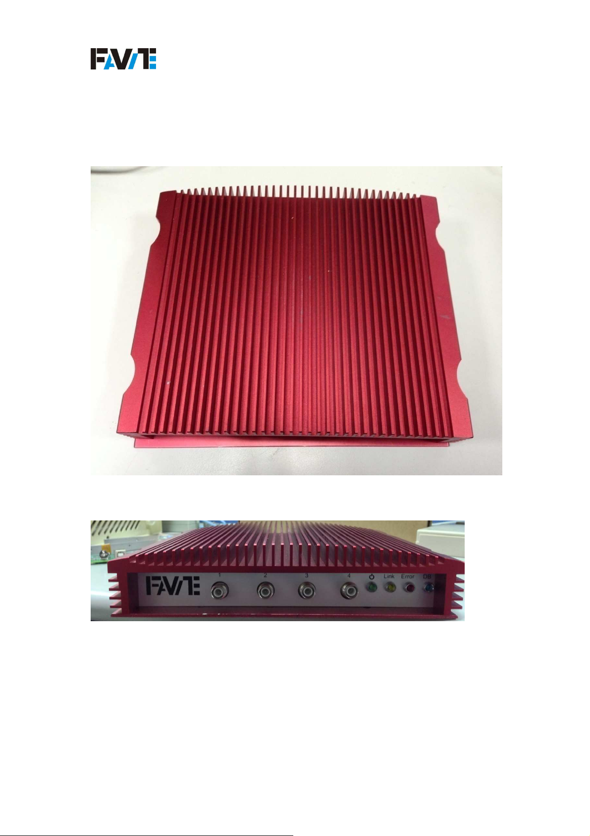
Figure 5: F740 (1)
9
v2.2.1.0, Copyright○C2013, Favite, Inc
Page 15
F740 User Guide
Figure 6: F740 (2)
Figure 7: FS-GF740 Power Supply and Adapter cable
10
v2.2.1.0, Copyright○C2013, Favite, Inc
Page 16
F740 User Guide
2.2 Diagnostic LEDs
The F740 is including diagnostic LEDs on the face of the reader to provide easy and
convenient external indication for various operating conditions:
POWER (green) – indicates that power is applied to the reader.
Read (yellow) – indicates that the reader is receiving data from a tag.
Fault (red) – indicates that a fault condition like CRC check error.
debug (blue) – indicates that the F740 is into debug mode
11
v2.2.1.0, Copyright○C2013, Favite, Inc
Page 17
F740 User Guide
Figure 8: FS-GF801 Reader Diagnostic LEDs
12
v2.2.1.0, Copyright○C2013, Favite, Inc
Page 18
F740 User Guide
Antenna Panel
The antenna panel is containing four coax antenna connector ports, which
isTNCconnector, as shown below. These are TNC connectors.
CAUTION: Reader antennas should be positioned so that personnel in the area for
prolonged periods may safely remain at least 23 cm (9 in) in an uncontrolled
environment from the antenna’s surface. See FCC OET Bulletin 56 “Hazards of radio
frequency and electromagnetic fields” and Bulletin 65 “Human exposure to radio
frequency electromagnetic fields.”
2.3 Demonstration Software Guide
Please refer to the document “FAVITE API Programming Guide_DotNet CSharp”,
“FAVITE SDK Getting Started Guide CSharp”, “FAVITE Saturn Demo API User
Guide” and “F740 GPIO Programming Guide_DotNet CSharp”.
13
v2.2.1.0, Copyright○C2013, Favite, Inc
 Loading...