

Page 1

INSTRUCTIONS FOR INSTALLATION AND USE
MONTAGE- UND GEBRAUCHSANWEISUNG
INSTRUCTIONS POUR L'INSTALLATION ET L’UTILISATION
ISTRUZIONI PER L'INSTALLAZIONE E L’USO
INSTRUCCIONES PARA INSTALACIÓN Y USO
INSTRUÇÕES DE INSTALAÇÃO Y UTILIZAÇÃO
AANWIJZING VOOR GEBRUIK EN INSTALLATIE
Page 2
ENGLISH
DESCRIPTION
The hood may be installed in the filtering or the ducting version.
Filtering version (Fig. 1): The hood aspirates the kitchen air saturated with fumes and odours, purifies it
through the grease filters and charcoal filters and returns clean air into the room. For constant efficiency, the
charcoal filters must be replaced periodically.
Ducting version (Fig. 2): The hood aspirates the kitchen air saturated with fumes and odours, passes it through
the grease filters and expels it to the outside through an outlet pipe. With this version the charcoal filters are
not required.
Decide from the outset on the type of installation (filtering or ducting). For greater efficiency, we recommend
you install the hood in the ducting version (if possible).
INSTALLATION
Before beginning installation, to better handle the hood, we advise removing the metal grid or the metal filter/s
(depending on the model purchased by you).
To remove the metal grid (Fig. 3), push the two stops towards the inside of the hood and turn the grid until this
can be removed.
To remove the metal filter/s (Fig. 4A or 4B), in line with the handle, push the stop inwards and pull the filter down.
INSTALLATION IN DUCTING VERSION:
Before fixing, the outlet pipe for air evacuation to the outside must be installed. Use an outlet pipe with:
- minimum indispensable length; - Minimum possible bends (maximum angle of bend:90°); - certified material
(according to the State); - an as smooth as possible inside. It is also advisable to avoid any drastic changes
in pipe cross-section (recommended diameter: 125 mm). For air evacuation to the outside, follow all the instructions
given on the “Warnings” sheet.
Decide on the position of the hole for the air outlet: The hole may be in the wall or the ceiling, according
to your requirements, but must be in vertical line with your hob. Bear in mind that the hood can expel air through
the rear opening A (Fig. 5) or through the top opening B.
Select the type of configuration most suited to your needs and proceed by mounting the flange C (Fig. 6)
on the opening selected for air evacuation (A or B): make the 3 flange clips and the catch D coincide with the
slots on the hood; slightly turn the flange clockwise until it locks. Close the other opening by mounting the “cap”
(E) in the same way: Make the 3 cap clips and the catch F coincide with the slots on the hood; slightly turn
the cap clockwise until it locks.
Drill the hole in the wall for the air outlet (133 mm diameter) referring to Fig. 7 where the measurements for
the various possibilities are indicated.
Prepare a suitable power supply. For the electrical connection, follow all the other instructions on the “Warnings”
sheet.
Proceed with fixing the hood: Based on your requirements, you can fit the hood on the wall or on a wall
unit of your kitchen. IMPORTANT: Respect the distance between the hob and lower part of the hood which must
be at least 650 cm.
Fixing to the wall: If you use the top opening B for the air outlet through the wall unit, before fixing the
hood to the wall, drill a hole of 133 mm diameter in the wall unit (Fig. 8). In any case, check the position of
the power outlet and consider where the power cable will run, since a hole might have to be made in the wall
unit to accommodate it. Draw a line on the wall in vertical line with your hob. Mark the 4 holes to be drilled
in the wall, respecting the distances indicated in Fig. 9; Make the 4 holes and fit the 4 screw anchors provided.
Take 2 of the screws provided (Fig. 10G) and insert them in the topmost screw anchors without however screwing
them down completely. Hang the hood on the 2 screws; Working from inside the hood, tighten the 2 screws
completely. Now proceed with final fixing by fitting the other 2 screws H (Fig. 11). Connect a flexible tube to the
hood flange, using a metal hose clamp. Tube and hose clamps are not provided. Make the electrical connection.
Fitting under wall unit: If you use the top opening B for the air outlet through the wall unit, before fixing
the hood to the unit, drill a hole of 133 mm diameter in the wall unit (Fig. 8). In any case, check the position
of the power outlet and consider where the power cable will run, since a hole might have to be made in the wall
unit to accommodate it. Drill 4 holes in the wall unit, respecting the distances indicated in Fig. 12. Push the hood
up against the wall unit and insert the 4 screws operating from inside the wall unit (the 4 screws are not provided).
Connect a flexible tube to the hood flange, using a metal hose clamp. Tube and hose clamps are not provided.
Make the electrical connection.
Installation is now complete. We recommend you:
• CHECK THAT THE DUCTING-FILTERING LEVER IS IN THE RIGHT POSITION: The lever is found on the motor
unit and must be positioned on the symbol (P) in the case of installation in ducting version (Fig. 13).
• also remember that the use of charcoal filter/s is not necessary with the ducting version; if these are fitted,
remove them and proceed as following according to the model type purchased:
Page 3
- if the hood features round charcoal filters (Fig. 14R), remove the charcoal filter by turning it clockwise.
- if the hood features a panel type charcoal filter (Fig. 15A or 16A or 17A), remove the charcoal filter by first
of all removing the two filter retainers M.
INSTALLATION IN FILTERING VERSION:
Prepare a suitable power supply. For the electrical connection, follow all the other instructions on the “Warnings”
sheet.
The 2 openings (A and B) on the hood (Fig. 5) must not be closed, since the air is recirculated into the
room through the front vents.
Proceed with fixing the hood: Based on your requirements, you can fit the hood on the wall or on a wall
unit of your kitchen. IMPORTANT: Respect the distance between the hob and lower part of the hood which must
be at least 650 cm.
Fixing to the wall: Before fixing the hood to the wall, check the position of the power outlet and consider
where the power cable will run, since a hole might have to be made in the wall unit to accommodate it. Draw
a line on the wall in vertical line with your hob. Mark the 4 holes to be drilled in the wall, respecting the distances
indicated in Fig.9; Make the 4 holes and fit the 4 screw anchors provided. Take 2 of the screws provided (Fig.
10G) and insert them in the topmost screw anchors without however screwing them down completely. Hang the
hood on the 2 screws; Working from inside the hood, tighten the 2 screws completely. Now proceed with final
fixing by fitting the other 2 screws H (Fig. 11). Make the electrical connection.
Fitting under wall unit: Before fixing the hood to the wall unit, check the position of the power outlet and
consider where the power cable will run, since a hole might have to be made in the wall unit to accommodate
it. Drill 4 holes in the wall unit, respecting the distances indicated in Fig. 12. Push the hood up against the wall
unit and insert the 4 screws operating from inside the wall unit (the 4 screws are not provided). Make the electrical
connection.
Installation is now complete. We recommend you:
• CHECK THAT THE DUCTING-FILTERING LEVER IS IN THE RIGHT POSITION: The lever is found on the motor
unit and must be positioned on the symbol (Q) in the case of installation in filtering version (Fig. 13).
• also remember that charcoal filter/s must be used in the case of the filtering version; check to see whether
such filters are already fitted; if necessary, proceed to fit as follows, depending on the model type purchased:
- if the hood features round charcoal filters (Fig. 18R), fit the charcoal filter by turning anti-clockwise.
- if the hood features a panel type charcoal filter/s (Fig. 15A or 17A), position the charcoal filter inside and fit
the two filter retainers to secure the charcoal filter.
OPERATION
Depending on the model, the unit is equipped with the following controls:
Controls as in Fig. 19: A = Light switch. B = Motor ON/OFF switch - speed I C = switch - speed II D
= switch - speed III E = Motor on light.
Controls as in Fig. 20: A = Light switch; position 0: light off; position 1: light on. B = Motor switch; position
0: motor off; position 1-2-3: Motor on at speed I, II and II. C = Motor on light.
Grease filter/s: Depending on the version, the hood features different types of grease filters:
Modular metal filter/s (of the type shown in Fig. 21 or 22): these are metal filters and must be periodically cleaned,
depending on extent of operation (at least every two months). Wash the filters with neutral detergent. To remove
the filters, in line with the handle, push the stop inwards and pull the filter down (Fig. 4A or 4B).
Panel type metal filter (as shown in Fig. 23N): this is a metal filter and is positioned inside the metal grid; the
filter must be periodically cleaned, depending on extent of operation (at least every two months). Wash the filter
with neutral detergent. To remove the filter, first of all remove the metal grid by pushing the two stops towards
the inside of the hood (Fig. 3); subsequently remove the two filter retainers inside the metal grid and remove the
panel type metal filter.
Panel type synthetic filter (as shown in Fig. 24P): this filter is made of white synthetic fibres and is located
inside the metal grid; it cannot be cleaned, but must be replaced from time to time according to use (at least
every two months). To remove the filter, first of all remove the metal grid, push the two stops towards the inside
of the hood (Fig. 3); next, remove the two filter retainers inside the metal grid and remove the panel type synthetic
filter.
Charcoal filter/s: the charcoal filters must be periodically replaced depending on extent of operation - on
average every 6 months. To remove the charcoal filters, proceed as follows, depending on the model purchased:
- if the hood features round charcoal filters (Fig. 14R), remove the charcoal filter by turning clockwise.
- if the hood features a panel type charcoal filter (Fig. 16A or 17A), remove the charcoal filter by first of all removing
the two filter retainers M.
Lighting:
To access the incandescent lamps, remove the metal grid or metal filter/s (depending on the model you have
purchased): to remove the metal grid (Fig. 3), push the two stops towards the inside of the hood and turn the
grid until this can be removed. To remove the metal filter/s (Fig. 4A or 4B), in line with the handle, push the stop
inwards and pull the filter down. Replace with lamps of the same kind (Fig. 25).
Warning: If you have a hood in the version with 2 motors, to take out the bulbs remove the glass light fitting
Page 4

proceeding as follows: prise the catches of the light fitting at point A and simultaneously move the glass of the
light fitting upwards (Fig. 26). If the round charcoal filters are mounted on your appliance, remove them first.
DEUTSCH
BESCHREIBUNG
Die Haube kann als Umluftversion oder als Abluftversion installiert werden.
Umluftversion (Abb. 1): die Haube saugt die mit Rauch und Gerüchen gesättigte Luft an und reinigt sie durch
die Fett- und die Kohlefilter. Danach wird die saubere Luft wieder in den Raum geleitet. Um die gleichmäßige
Wirksamkeit der Kohlefilter zu erhalten, müssen sie regelmäßig ausgetauscht werden.
Abluftversion (Abb. 2): die Haube saugt die mit Rauch und Gerüchen gesättigte Luft an, leitet sie durch
die Fettfilter und gibt sie über ein Abführungsrohr nach außen ab. Diese Version benötigt keine Kohlefilter.
Entscheiden Sie sich von Anfang an für einen Installationstyp (Umluft oder Abluft). Um eine größere Wirkung
zu erzielen, empfehlen wir die Installation einer Haube in Abluftversion (falls möglich).
INSTALLATION
Vor Beginn des Einbaus sollten zur leichteren Handhabung der Haube das Metallgitter oder die/der Metallfilter (je
nach dem von Ihnen erworbenen Modell) entfernt werden.
Zum Entfernen des Metallgitters (Abb. 3), die 2 Festhalter ins Innere der Haube drücken und das Gitter drehen,
bis es sich abnehmen läßt.
Zum Entfernen die/der Metallfilter (Abb. 4A oder 4B), den Festhalter in der Nähe des Griffs nach innen drücken
und den Filter nach unten ziehen.
INSTALLATION DER ABLUFTVERSION:
Vor der Befestigung muss das Rohr zur Abführung der Luft nach außen angebracht werden. Ein Abführungsrohr
verwenden, das folgende Eigenschaften besitzt: - erforderliche Mindestlänge; - so wenig Kurven wie möglich
(maximale Kurvenkrümmung:90°); - zulässiges Material (Landesnormen); - Innenseite so glatt wie möglich. Es wird
außerdem empfohlen, starke Wechsel des Rohrdurchmessers zu vermeiden (empfohlener Durchmesser: 125 mm).
Für die Luftabführung nach außen alle weiteren Angaben im Blatt “Hinweis” befolgen.
Wählen Sie die Position der Öffnung für die Luftabführung: Die Öffnung kann sich je nach Ihren Bedürfnissen
an der Wand oder der Decke befinden, und muss sich in jedem Fall in senkrechter Linie zu Ihrem Kochfeld befinden.
Beachten Sie, dass die Haube die Luft über die hintere Öffnung A (Abb. 5) ableiten kann oder über die obere
Öffnung B.
Wählen Sie die für Sie am besten geeignete Lösung und fahren Sie mit der Montage des Flansches C (Abb.
6) auf der zur Luftableitung gewählten Öffnung fort (A oder B)die 3 Laschen des Deckels und den Feststeller D
auf die Schlitze auf der Haube ausrichten; den Flansch leicht im Uhrzeigersinn drehen, bis er sperrt. Die andere
Öffnung schließen, dazu den “Deckel” (E) in der gleichen Weise darauf montieren: die 3 Laschen des Deckels
und den Feststeller F auf die Schlitze auf der Haube ausrichten; den Deckel leicht im Uhrzeigersinn drehen, bis
er sperrt.
Das Bohrloch in der Wand zur Ableitung der Luft ausführen (Durchmesser 133 mm), hierbei die Abb. 7 beachten,
in der die Maße für die verschiedenen Möglichkeiten angegeben sind.
Für eine angemessene Stromversorgung sorgen. Für den Elektroanschluss beachten Sie alle Angaben im Blatt
“Hinweis”.
Fahren Sie mit der Befestigung des Gerätes fort: je nach Ihren Bedürfnissen können Sie die Haube an der
Wand oder am Oberschrank Ihrer Küche befestigen. WICHTIG: der Abstand zwischen der Haube und dem Kochfeld
muss mindestens 650 cm betragen.
Wandmontage: Wenn Sie die obere Öffnung B für die Luftableitung durch den Oberschrank benutzen, muss
vor Befestigung der Haube an der Wand im Oberschrank ein Loch mit einem Durchmesser von 133 mm angebracht
werden (Abb. 8). In jedem Fall muss die Position der Steckdose festgestellt und der eventuelle Verlauf des
Speisekabels berücksichtigt werden (für das Speisekabel könnte eine spezielle Öffnung im Oberschrank erforderlich
werden). Zeichnen Sie eine Linie auf die Wand, vertikal zu Ihrem Kochfeld. Markieren Sie die 4 anzubringenden
Löcher auf der Wand, dabei sind die in Abb. 9 angegebenen Maße zu beachten; die 4 Bohrungen ausführen und
die 4 (mitgelieferten) Dübel einstecken.Nehmen Sie 2 der mitgelieferten Schrauben (Abb. 10G) und fügen Sie sie
in die weiter oben befindlichen Dübel, ohne sie jedoch vollständig anzuschrauben. Bringen Sie die Haube zur Wand
und hängen Sie sie an den 2 Schrauben auf; Von der Innenseite der Haube aus müssen die beiden Schrauben
gut angezogen werden. Nehmen Sie die endgültige Befestigung vor, dazu die beiden Schrauben H einfügen (Abb.
11). Schließen Sie einen Schlauch an den Flansch des Gerätes an, dazu eine Metallschelle verwenden. Schlauch
und Schellen werden nicht mitgeliefert. Den elektrischen Anschluss herstellen.
Befestigung an der Unterseite des Hängeschranks: Wenn Sie die obere Öffnung B für den Luftaustritt durch
den Oberschrank benutzen, ist der Oberschrank vor Befestigung der Haube am Schrank mit einem Loch mit dem
Durchmesser 133 mm zu versehen (Abb. 8). In jedem Fall muss die Position der Steckdose festgestellt und der
Page 5
eventuelle Verlauf des Speisekabels berücksichtigt werden (für das Speisekabel könnte eine spezielle Öffnung im
Oberschrank erforderlich werden). 4 Löcher in den Oberschrank bohren, dabei die in Abb. 12 angegebenen Maße
einhalten. Die Haube neben den Oberschrank bringen und 4 Schrauben einfügen, dabei vom Innern des Oberschranks
aus vorgehen (die 4 Schrauben werden nicht mitgeliefert). Schließen Sie einen Schlauch an den Flansch des Gerätes
an, dazu eine Metallschelle verwenden. Schlauch und Schellen werden nicht mitgeliefert. Den elektrischen Anschluss
herstellen.
Nun ist der Einbau beendet ; wir empfehlen folgendes:
• ÜBERPRÜFEN, DASS SICH DER HEBEL ANSAUGEN-FILTERN IN DER KORREKTEN POSITION BEFINDET : der
Hebel befindet sich auf dem Motoraggregat und muss auf dem Symbol positioniert sein (P) wenn die Abluftversion
installiert ist (Abb. 13).
• Beachten Sie, dass für die Abluftversion keine Kohlefilter benötigt werden; sollten diese bereits montiert sein,
entfernen Sie sie unter Befolgung der nachstehenden Anweisungen entsprechend dem von Ihnen erworbenen Modell:
- wenn die Haube mit runden Kohlefiltern ausgestattet ist (Abb. 14R), entfernen Sie die Kohlefilter durch Drehen
derselben im Uhrzeigersinn.
- wenn die Haube mit einem Kohlefilterpaneel ausgestattet ist (Fig. 15A oder 16A oder 17A), entfernen Sie den
Kohlefilter durch vorheriges Abnehmen der beiden Filterhalter M.
INSTALLATION UMLUFTVERSION:
Für eine angemessene Stromversorgung sorgen. Für den Elektroanschluss beachten Sie alle Angaben im Blatt
“Hinweis”.
Die beiden Öffnungen (A und B) auf dem Gerät (Abb. 5) dürfen nicht geschlossen sein, da die Luft durch
die vorderen Schlitze wieder in den Raum geleitet wird.
Fahren Sie mit der Befestigung des Gerätes fort: je nach Ihren Bedürfnissen können Sie die Haube an der
Wand oder am Oberschrank Ihrer Küche befestigen. WICHTIG: der Abstand zwischen der Haube und dem Kochfeld
muss mindestens 650 cm betragen.
Wandmontage: Vor Befestigung des Gerätes an der Wand die Position der Steckdose überprüfen und den
eventuellen Verlauf des Speisekabels berücksichtigen (für das Speisekabel könnte eine spezielle Öffnung am
Oberschrank erforderlich werden). Zeichnen Sie eine Linie auf die Wand, vertikal zu Ihrem Kochfeld. Markieren Sie
die 4 anzubringenden Löcher auf der Wand, dabei sind die in Abb. 9 angegebenen Maße zu beachten; die 4
Bohrungen ausführen und die 4 (mitgelieferten) Dübel einstecken. Nehmen Sie 2 der mitgelieferten Schrauben
(Abb.10G) und fügen Sie sie in die weiter oben befindlichen Dübel, ohne sie jedoch vollständig anzuschrauben.
Bringen Sie die Haube zur Wand und hängen Sie sie an den 2 Schrauben auf; von der Innenseite der Haube aus
müssen die beiden Schrauben gut angezogen werden. Nehmen Sie die endgültige Befestigung vor, dazu die beiden
Schrauben H einfügen (Abb. 11). Den elektrischen Anschluss herstellen.
Befestigung an der Unterseite des Hängeschranks: Vor Befestigung des Gerätes am Oberschrank die Position
der Steckdose überprüfen und den eventuellen Verlauf des Speisekabels berücksichtigen (für das Speisekabel
könnte eine spezielle Öffnung am Oberschrank erforderlich werden). 4 Löcher in den Oberschrank bohren, dabei
die in Abb.12 angegebenen Maße einhalten. Die Haube neben den Oberschrank bringen und 4 Schrauben einfügen,
dabei vom Innern des Oberschranks aus vorgehen (die 4 Schrauben werden nicht mitgeliefert). Den elektrischen
Anschluss herstellen.
Nun ist der Einbau beendet ; wir empfehlen folgendes:
• ÜBERPRÜFEN, DASS SICH DER HEBEL ANSAUGEN-FILTERN IN DER KORREKTEN POSITION BEFINDET: der
Hebel befindet sich auf dem Motoraggregat und muss auf dem Symbol (Q) positioniert sein, wenn die Umluftversion
installiert ist (Abb. 13).
• Beachten Sie, dass bei der Umluftversion der Gebrauch von Kohlefilter (n) erforderlich ist; uberprüfen Sie, ob
die Filter bereits installiert sind; falls erforderlich, montieren Sie diese wie nachstehend beschrieben ist, entsprechend
dem von Ihnen erworbenen Modell:
- wenn die Haube mit runden Kohlefiltern ausgestattet ist (Abb. 18R), hängen Sie den Kohlefilter durch Drehen
desselben im Gegenuhrzeigersinn ein.
- wenn die Haube mit einem Kohlefilterpaneel ausgestattet ist (Abb. 15A oder 16A oder 17A), legen Sie das(die)
Kohlefilterpaneel(e) auf die innere Seite der Fettfilterkassette und setzen Sie die zwei Halter wieder ein, um das
Kohlefilterpaneel zu befestigen.
FUNKTIONSWEISE
Je nach Version ist das Gerät mit folgenden Bedienungsarten ausgestattet:
Bedienung in Abb. 19:
A = Lichtschalter. B = Motorschalter ON/OFF bei der I. Geschwindigkeit. C = Schalter II. Geschwindigkeit.
D = Schalter III. Geschwindigkeit. E = Motorfunktionsanzeige.
Bedienung in Abb. 20:
A = Lichtschalter; Position 0: Licht aus; Position 1: Licht an. B = Motorschalter;Position 0: Motor ausgeschaltet;
Position 1-2-3: Motor eingeschaltet mit erster, zweiter und dritter Geschwindigkeit. C: Motorfunktionsanzeige.
Fettfilter:
Je nach Version wird die Haube mit verschiedenen Fettfiltern geliefert:
Metallfilterkassette (wie in Abb. 21 oder 22 gezeigt): diese Filter bestehen aus Metall und sind je nach Benutzung
Page 6

periodisch zu reinigen (wenigstens alle zwei Monate). Den Filter mit neutralem Reinigungsmittel abwaschen. Zum
Entfernen der Filter (Abb. 3), den Festhalter in der Nähe des Griffs nach innen drücken und den Filter nach unten
ziehen (Abb. 4A oder 4B).
Metallfilterpaneele (wie in Abb. 23N gezeigt): dieser aus Metall bestehende Filter befindet sich im Innern des
Metallgitters und ist je nach Benutzung periodisch (wenigstens alle zwei Monate) zu reinigen. Den Filter mit neutralem
Reinigungsmittel abwaschen. Zum Entfernen der Metallfilter, das Metallgitter abnehmen, dazu die beiden Feststeller
nach dem Haubeninnern schieben (Abb. 3); anschließend die 2 im Innern des Metallgitters befindlichen Filterhalter
entfernen und Metallfilterpaneel abnehmen.
Synthetikfilterpaneel (wie in Abb. 24P gezeigt): dieser aus weißer Synthetikfaser bestehende Filter befindet sich
im Innern des Metallgitters und ist je nach Benutzung periodisch (wenigstens alle zwei Monate) zu ersetzen. Zum
Entfernen der Kohlefilter, das Metallgitter abnehmen, dazu die beiden Feststeller nach dem Haubeninnern schieben
(Abb. 3); anschließend die 2 im Innern des Metallgitters befindlichen Filterhalter entfernen und Synthetikfilterpaneel
herausnehmen.
Kohlefilter: Der(die) Kohlefilter je nach Benutzung ersetzen; in der Regel alle 6 Monate. Zum Entfernen der
Kohlefilter, wie folgt vorgehen, je nach dem von Ihnen erworbenen Modell:
- wenn die Haube mit runden Kohlefiltern ausgestattet ist (Abb. 14R), entfernen Sie den Kohlefilter durch Drehen
derselben im Uhrzeigersinn.
- wenn die Haube mit einem Kohlefilterpaneel (Abb. 15A oder 16A oder 17A) ausgestattet ist, ist der Kohlefilter
durch vorheriges Entfernen der 2 Filterhalter M herauszunehmen.
Beleuchtung:
Um an die Glühlampen zu gelangen, muß je nach dem von Ihnen erworbenen Modell das Metallgitter oder die
Metallfilterkassette(n) abgenommen werden: Zum Entfernen des Metallgitters (Abb. 3), die 2 Festhalter ins Innere
der Haube drücken und das Gitter drehen, bis es sich abnehmen läßt. Zum Entfernen des(der) Metallfilter (Abb.
4A oder 4B), den Festhalter in der Nähe des Griffs nach innen drücken und den Filter nach unten ziehen. Die
Lampen durch neue des gleichen Typs ersetzen (Abb. 25).
Achtung: Wenn Sie die Dunstabzugshaube in der 2-Motoren-Version besitzen, muss zum Wechsel der Lampen die
Glasblende wie folgt entfernt werden: in Punkt A auf die Halterungen der Blende drücken und gleichzeitig das Glas
der Blende nach oben schieben (Abb. 26); sind an Ihrem Gerät die runden Kohlefilter montiert, so müssen diese
zuvor entfernt werden.
FRANCAIS
DESCRIPTION
Cette hotte peut être installée en version recyclage ou en version aspirante.
Version Recyclage (Fig. 1) : votre hotte aspire l’air de la cuisine imprégné de fumée et d’odeurs, en l’épurant
à travers les filtres à graisse ainsi qu’à travers les filtres à charbon pour le renvoyer dans la pièce, propre. Afin
que votre hotte soit efficace d’une façon constante, il est nécessaire de remplacer les filtres à charbon
périodiquement.
Version aspirante (Fig. 2) : votre hotte aspire l’air de la cuisine imprégnée de fumée et d’odeurs, en le faisant
passer à travers les filtres à graisse, puis en expulsant à l’extérieur à travers un tuyau d’évacuation. Dans cette
version l’emploi de filtres à charbon n’est pas nécessaire.
Vous devez décider dès le début quel type d’installation vous souhaitez (recyclage ou aspirante). Afin d’avoir
une hotte au rendement optimal, nous vous conseillsons d’installer une hotte version aspirante (si cela est possible).
INSTALLATION
Avant de commencer l’installation, pour mieux manipuler la hotte, il est conseillé d’enlever la grille métallique ou
le/les filtre/s métalliques (en fonction du modèle en votre possession).
Pour enlever la grille métallique (Fig. 3), poussez les deux fixations vers l’intérieur de la hotte et tournez la grille
jusqu’à son extraction.
Pour enlever le/les filtre/s métalliques (Fig. 4A ou 4B), en face de la poignée, poussez la fixation vers l’intérieur
puis tirez le filtre vers le bas.
INSTALLATION VERSION ASPIRANTE :
Avant de l’assembler, il est nécessaire de prévoir le tuyau pour l’évacuation de l’air à l’extérieur. Employez
un tuyau d’évacuation qui a : - la longueur minimum indispensable ; - le moins de courbes possible (angle maximum
des courbes : 90°) ; - qui soit fait d’une matière autorisée par les normes en vigueur; - la surface intérieure la
plus lisse possible. Nous vous conseillons aussi d’éviter les changements brusques de section du tuyau (diamètre
conseillé : 125 mm). Pour l’évacuation de l’air à l’extérieur, suivez toutes les autres indications données par le
feuille “Attention”.
Etudiez la position du trou pour l’évacuation de l’air : ce trou peut être fait dans le mur ou dans le plafond,
suivant vos exigences, il doit en tout cas être fait verticalement par rapport à votre plan de cuisson. Tenez compte
Page 7

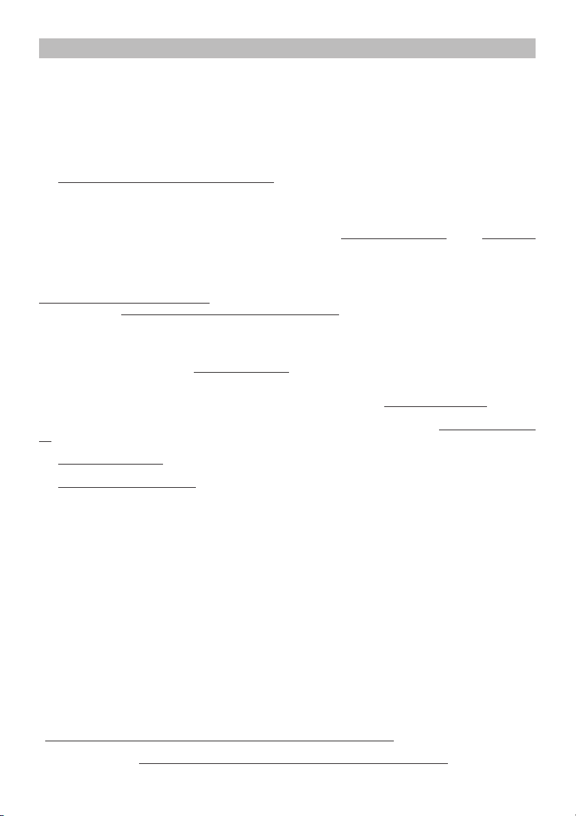
Wiring Diagram (1 MOTOR) - Elektrischer Schaltplan (1 MOTOR) Schéma Électrique (1 MOTEUR) - Schema Elettrico (1 MOTORE) -
Esquema Eléctrico (1 MOTOR) - Esquema Eléctrico (1 MOTOR) -
Elektrisch Schema (1 MOTOR)
HOOD WITH SLIDE CONTROLS - GERÄT MIT SCHIEBEKNOPF-BEDIENUNG HOTTE AVEC COMMANDES A CHARIOT - CAPPA CON COMANDI A SLITTA CAMPANA CON MANDOS DESLIZANTES - EXAUSTOR COM COMANDOS DESLIZANTES AFZUIGKAP MET SCHUIFKNOPBEDIENING
HOOD WITH BUTTON CONTROLS - GERÄT MIT TASTENBEDIENUNG
HOTTE AVEC COMMANDES A BOUTONS - CAPPA CON COMANDI A PULSANTI
CAMPANA CON PULSANTES - EXAUSTOR COM COMANDOS DE BOTÕES
AFZUIGKAP MET DRUKKNOPBEDIENING
Page 8

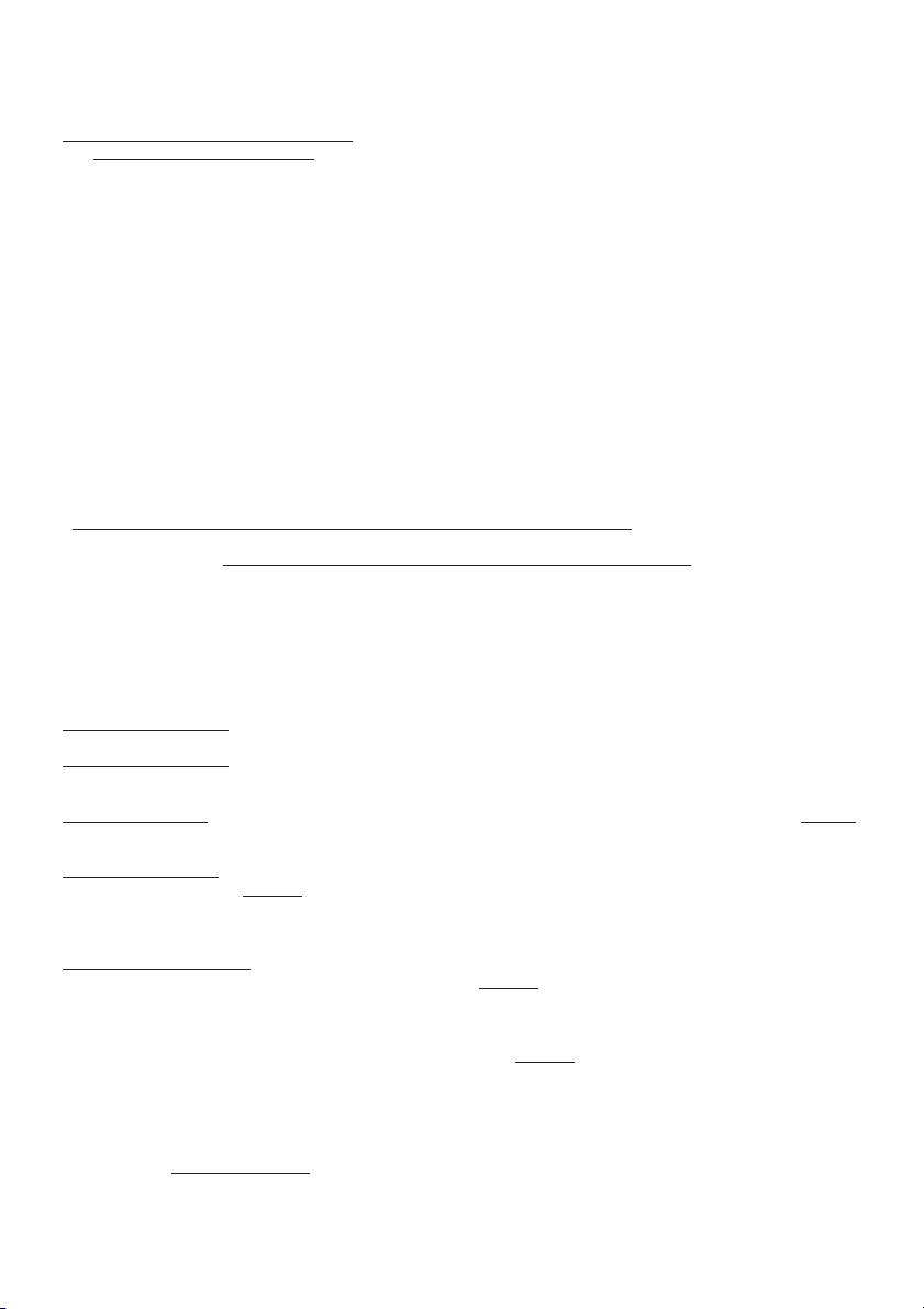
Wiring Diagram (2 MOTORS) - Elektrischer Schaltplan (2 MOTOREN) -
Schéma Électrique (2 MOTEURS) - Schema Elettrico (2 MOTORI) -
Esquema Eléctrico (2 MOTORES) - Esquema Eléctrico (2 MOTORES) -
Elektrisch Schema (2 MOTOREN)
HOOD WITH SLIDE CONTROLS - GERÄT MIT SCHIEBEKNOPF-BEDIENUNG HOTTE AVEC COMMANDES A CHARIOT - CAPPA CON COMANDI A SLITTA CAMPANA CON MANDOS DESLIZANTES - EXAUSTOR COM COMANDOS DESLIZANTES AFZUIGKAP MET SCHUIFKNOPBEDIENING
HOOD WITH BUTTON CONTROLS - GERÄT MIT TASTENBEDIENUNG
HOTTE AVEC COMMANDES A BOUTONS - CAPPA CON COMANDI A PULSANTI
CAMPANA CON PULSANTES - EXAUSTOR COM COMANDOS DE BOTÕES
AFZUIGKAP MET DRUKKNOPBEDIENING
Page 9

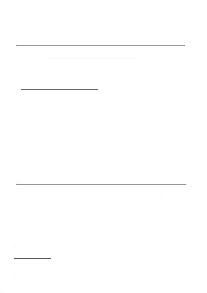
1
2
3
5
B
A
C
4A
4B
D
F
6
E
Page 10

7
Ø133
8
85
9
Ø 8mm
min650
min650
min
940
Ø 133
85
720
10
G
G
A
=
=
44
732
MODELS A
50cm 44cm
55cm 49cm
60cm 54cm
70cm 64cm
80cm 74cm
90cm 84cm
11
H
Page 11

12
Ø 6mm
MODELS X
50cm 41cm
55cm 46cm
60cm 51cm
70cm 61cm
80cm 71cm
90cm 81cm
256
34
X
=
=
13
15
17
P
M
M
R
14
Q
M
A
16
18
A
A
R
Page 12

19
A
B
C
D
E
C
A
B
20
21
23
24
22
N
P
26
25
04306555/3 - SP2000 sen.nor.
Page 13

WARNING - HINWEIS - ATTENTION - AVVERTENZE - ADVERTENCIA
ADVERTENCIAS - OPGELET
ENGLISH
WARNING
The distance between the supporting surface for the cooking
vessels on the hob and the lower part of the hood must be at
least 65 cm. If the instructions for installation for the hob
specify a greater distance, this has to be taken into account.
The air collected must not be conveyed into a duct used to
blow off smokes from appliances fed with an energy other
than electricity (central heating systems, thermosiphons,
water-heaters, etc.).
Comply with the official instructions provided by the competent
authorities in merit when installing the disposal duct. In
addition, exhaust air should not be discharged into a wall
cavity, unless the cavity is designed for that purpose.
The room must be well aerated in case a hood and some
other heat equipment fed with an energy other than electricity
(gas, oil, coal heaters, etc) operate at the same time.
In fact the intake hood, disposing of air, could create a
vacuum in the room. The vacuum should not exceed 0,04mbar.
This prevents the gas exhausted by the heat source from
being intaken again. It is therefore advisable to ensure the
room contains air taps able to ensure a steady flow of fresh
air.
Check the data label inside the appliance; if the symbol
( ) is printed, read the following: this appliance has
such technical particulars that it belongs to class II
insulation, therefore it must not be earthed.
The following warning is valid in the United Kingdom only: in
case your cable is not furnished with a plug, read the following
instructions; as the colours of the wires in the mains lead of
this appliance may not correspond with the coloured markings
identifying the terminals in your plug, proceed as follows: –
the wire which is coloured blue must be connected to the
terminal which is marked with the letter N or coloured black;
– the wire which is coloured brown must be connected to the
terminal which is marked with the letter L or coloured red. –
terminal of a three-pin plug.
Check the data label inside the appliance; if the symbol
) is NOT printed, read the following: ATTENTION:
(
This appliance must be earthed. When making the electrical
connections, check that the current socket has a ground
connection.
The following warning is valid in the United Kingdom only: in
case your cable is not furnished with a plug, read the following
instructions; as the colours of the wires in the mains lead of
this appliance may not correspond with the coloured markings
identifying the terminals in your plug, proceed as follows:
– the wire which is coloured green and yellow must be
connected to the terminal in the plug which is marked with the
letter E or by the earth symbol [
green and yellow; – the wire which is coloured blue must be
connected to the terminal which is marked with the letter N or
coloured black; – the wire which is coloured brown must be
connected to the terminal which is marked with the letter L or
coloured red.
When making the electrical connections, check that the
voltage values correspond to those indicated on the data
plate inside the appliance itself. In case your appliance is not
furnished with a non separating flexible cable and has no
plug, or has not got any other device ensuring omnipolar
disconnection from the electricity main, with a contact opening
distance of at least 3 mm, such separating device ensuring
disconnection from the main must be included in the fixed
installation. If your unit features a power lead and plug,
position this so the plug is accessible.
Always switch off the electricity supply before carrying out
any cleaning or servicing operations on the appliance.
], or coloured green or
USE
Avoid using materials which could cause spurts of flame
(flambées) near the appliance.
When frying, take particular care to prevent oil and grease
from catching fire. Already used oil is especially dangerous in
this respect. Do not use uncovered electric grates.
To avoid possible risks of fire always comply with the indicated
instructions when cleaning anti-grease filters and when
removing grease deposits from the appliance.
MAINTENANCE
Thorough servicing guarantees correct and long-lasting
operation.
Any fat deposits should be removed from the appliance
periodically depending on amount of use (at least every 2
months). Avoid using abrasive or corrosive products. To
clean painted appliances on the outside, use a cloth dipped
in lukewarm water and neutral detergent. To clean steel,
copper or brass appliances on the outside, it is always best
to use specific products, following the instructions on the
products themselves. To clean the inside of the appliance,
use a cloth (or brush) dipped in denatured ethyl alcohol.
DEUTSCH
HINWEIS
Der Mindestabstand zwischen der Topf-Trägerfläche auf der
Kochmulde und dem unteren Teil der Abzughaube muss 65
cm betragen. Geben die Installationsanleitungen der
Kochmulde einen höheren Abstand an, so ist dieser
einzuhalten.
Ein Anschluss der Abluftleitungen an Verbrennungsabgaskamine (zum Beispiel Zentralheizung, Heizgeräte,
Badezimmeröfen usw.) ist nicht gestattet.
In jedem Fall sind bei der Ableitung der Abluft die behördlichen
Vorschriften zu beachten. Desweiteren darf die Abluft nur
dann durch ein Loch in der Wand geleitet werden, wenn
dieses für diesen Zweck bestimmt ist.
Achtung! Bei gleichzeitigem Betrieb einer AbluftDunstabzugshaube und einer raumluftabhängigen
Feuerstätte (wie z. B. gas-, öl- oder kohlebetriebene
Heizgeräte, Durchlauferhitzer, Warmwasserbereiter) ist
Vorsicht geboten, da beim Absaugen der Luft durch die
Dunstabzugshaube dem Aufstellraum die Luft entnommen
wird, die die Feuerstätte zur Verbrennung benötigt. Ein
gefahrloser Betrieb ist möglich, wenn bei gleichzeitigem
Betrieb von Haube und raumluftabhängiger Feuerstätte im
Aufstellraum der Feuerstätte ein Unterdruck von höchstens
0,04 mbar erreicht wird und damit ein Rücksaugen der
Feuerstättenabgase vermieden wird. Daher den Raum mit
Lüftungsanschlüssen versehen, die einen konstanten Zustrom
von Frischluft gewährleisten.
Das Typenschild im Innern des Geräts kontrollieren: Den
folgenden Anweisungen folgen, falls das Symbol ( )
erscheint; dieses Gerät weist konstruktive technische
Details auf, die unter die Isolierungsklasse II fallen und
deshalb muss es nicht geerdet werden.
Das Typenschild im Innern des Geräts kontrollieren: den
folgenden Anweisungen folgen, falls das Symbol ( )
NICHT erscheint; ACHTUNG: dieses Gerät muss geerdet
werden. Beim elektrischen Anschluss sicherstellen, dass die
Steckdose eine Erdung aufweist.
Beim elektrischen Anschluss muss überprüft werden, ob die
Spannungswerte des Stromnetzes mit den Werten auf dem
im Innern des Gerätes angebrachten Typenschilds
übereinstimmen. Falls Ihr Gerät nicht mit einem fest
angeschlossenem Kabel mit Stecker oder einer sonstigen
Page 14

Vorrichtung, die eine allpolige Unterbrechung mit einer
Kontaktöffnung von mindestens 3 mm versehen ist, so müssen
die entsprechenden Trennvorrichtungen bei der festen
Installation vorgesehen werden. Das Gerät so aufstellen,
dass der Stecker zugänglich ist, falls Ihr Gerät mit einem
Netzkabel mit Stecker ausgestattet ist.
Vor jeder Reinigungs- oder Wartungsarbeit muss das Gerät
vom Stromnetz getrennt werden.
GEBRAUCH
In der unmittelbaren Nähe des Geräts die Benutzung von
flammenerzeugenden Materialien (Flambieren) vermeiden.
Beim Frittieren besonders auf die Brandgefahr achten, die
durch Öl und Fette verursacht wird. Besonders gefährlich ist
die Entflammbarkeit von bereits benutztem Öl. Keine offenen
Elektrogrills verwenden.
Zur Vermeidung einer möglichen Brandgefahr die
Anweisungen zur Reinigung der Fettfilter und zur Entfernung
eventueller Fettablagerungen auf dem Gerät beachten.
WARTUNG
Nur eine sorgfältige Pflege garantiert auf Dauer eine gute
Leistung und Funktion des Geräts.
Die Entfernung eventueller Fettablagerungen vom Gerät
erfolgt in regelmäßigen Abständen in Abhängigkeit von der
Benutzung (zumindest alle zwei Monate). Die Verwendung
von scheuernden oder korrosiven Produkten vermeiden. Für
die äußere Reinigung von lackierten Geräten ein mit
lauwarmen Wasser und Neutralreiniger angefeuchtetes Tuch
verwenden; für die äußere Reinigung der Geräte aus Stahl,
Kupfer und Messing wird die Verwendung von Spezial-
produkten empfohlen, wobei die auf dem Produkte
angegebenen Anweisungen zu beachten sind; für die innere
Reinigung der Geräte einen in denaturalisierten Äthylalkohol
eingetauchten Lappen (oder Pinsel) verwenden.
FRANCAIS
ATTENTION
La distance minimum entre la surface de support des
casseroles sur le plan de cuisson et la partie inférieure de la
hotte doit être de 65 cm. Si les consignes, pour l’installation
du plan de cuisson, indiquent une plus grande distance, il faut
en tenir compte.
L'air aspiré ne doit pas être canalisé dans un conduit qui est
utilisé pour évacuer les fumées produites par des appareils
alimentés par des sources d'énergies autres que l'énergie
électrique (installations de chauffage central, radiateurs,
chauffe-eau, etc.).
Pour évacuer l'air qui doit être éliminé respectez les
prescriptions des autorités compétentes. De plus l'air qui doit
être évacué ne doit pas être déchargé dans une cavité du
mur, à moins que cette cavité soit prévue pour ce but.
Prévoyez une aération de la pièce adéquate quand une hotte
et des appareils alimentés par une énergie autre que l'énergie
électrique (poêle à gaz, à huile, à charbon etc.) sont utilisés
en même temps. En effet, en évacuant l'air, la hotte pourrait
créer une dépression dans la pièce. La pression négative de
la pièce ne doit pas dépasser 0,04mbar, évitant ainsi que la
source de chaleur provoque un appel des gaz qui doivent être
évacués. Il est donc nécessaire d'équiper la pièce de prises
d'air alimentant un flux d'air frais constant.
Contrôler la plaque des caractéristiques techniques se
trouvant à l’intérieur de l’appareil; si le symbole ( )
figure sur la plaque suivre les instructions suivantes: cet
appareil est construit pour appartenir à la classe
d’isolation II ; il ne doit donc pas être relié à la terre.
Contrôler la plaque des caractéristiques techniques se
trouvant à l’intérieur de l’appareil; si le symbole ( ) NE
figure pas sur la plaque suivre les instructions suivantes:
ATTENTION: cet appareil doit être relié à la terre. Lors du
raccordement électrique s’assurer que la prise de courant est
équipée d’une connexion de mise à la terre.
Lors du raccordement électrique assurez-vous que les valeurs
de tension correspondent à celles qui sont indiquées sur la
plaque des caractéristiques de l’appareil, qui se trouve à
l'intérieur de celui-ci. Si votre appareil, n'a pas de câble
flexible qui ne peut pas être séparé ni de prise, ou bien d'autre
dispositif qui garantisse le débranchement de tous les pôles
du réseau, avec une distance d'ouverture entre les contacts
d'au moins 3 mm, ces dispositifs de séparation du réseau
doivent alors être prévus dans l'installation fixe. Si votre
appareil est muni d’un câble d’alimentation, positionner
l’appareil de manière à ce que la fiche soit accessible.
Avant de procéder à une opération d’entretien ou de nettoyage
quelconque, débranchez l’appareil.
UTILISATION
Evitez d'utiliser des matériaux qui provoquent des flammes à
proximité de l'appareil.
Dans le cas de fritures, faites tout particulièrement attention
au danger d’incendie que représentent les huiles et les corps
gras. A cause de son inflammabilité l’huile usagée est
particulièrement dangereuse. N'utilisez pas de grils électriques
découverts.
Pour éviter des risques d'incendie possibles suivez les
instructions données concernant le nettoyage des filtres à
graisse et sur la façon d'enlever des dépôts éventuels de
graisse sur l'appareil.
ENTRETIEN
Un entretien soigné est une garantie de bon fonctionnement
et de bon rendement de votre appareil dans le temps.
L’élimination, d’éventuels dépôts de graisse sur l’appareil,
doit être effectuée en fonction de l’utilisation de ce dernier (au
moins tous les 2 mois). Il faut éviter d’utiliser des produits
contenant des abrasifs ou des corrosifs. Pour le nettoyage
extérieur des appareils peints, utiliser un chiffon mouillé avec
de l’eau tiède et un détersif neutre. Pour le nettoyage extérieur
des appareils en acier, en cuivre et en laiton il est conseillé
d’utiliser des produits spécifiques et de suivre les instructions
fournies sur le produit. Pour le nettoyage de l’intérieur de
l’appareil, utiliser un chiffon (ou un pinceau) imbibé d’alcool
dénaturé.
ITALIANO
AVVERTENZE
La distanza minima tra la superficie di supporto delle pentole
sul piano di cottura e la parte inferiore della cappa deve
essere 65 cm. Se le istruzioni per l’installazione del piano di
cottura specificano una distanza maggiore, questa deve
essere tenuta in considerazione.
L'aria raccolta non deve essere convogliata in un condotto
usato per lo scarico di fumi di apparecchi alimentati con
energia diversa da quella elettrica (impianti di riscaldamento
centralizzati, termosifoni, scaldabagni ecc.).
Per lo scarico dell'aria da evacuare rispettare le prescrizioni
delle autorità competenti. Inoltre l'aria da scaricare non deve
essere eliminata attraverso una cavità del muro a meno che
tale cavità non sia destinata a questo scopo.
Prevedere un'adeguata areazione del locale quando una
cappa e apparecchi alimentati con energia diversa da quella
elettrica (stufe a gas, ad olio, a carbone ecc), vengono usati
contemporaneamente. Infatti la cappa aspirante evacuando
l'aria potrebbe creare una pressione negativa nella stanza.
La pressione negativa del locale non deve superare i 0,04
mbar, evitando così il risucchio dei gas di scarico della fonte
di calore. Pertanto attrezzare il locale con delle prese d’aria
che alimentino un flusso costante di aria fresca.
Controllare la targa caratteristiche tecniche posta all'interno dell'apparecchio; se sulla targa compare il simbo-
) seguire le seguenti istruzioni: questo apparec-
lo (
chio presenta accorgimenti tecnici costruttivi tali da
essere annoverato nella classe di isolamento II e pertanto non deve essere collegato a terra.
Controllare la targa caratteristiche tecniche posta all'interno dell'apparecchio; se sulla targa NON compare il
Page 15

simbolo ( ) seguire le seguenti istruzioni: ATTENZIO-
NE: questo apparecchio deve essere collegato a terra.
Nell’operazione di collegamento elettrico assicurarsi che la
presa di corrente sia munita di collegamento di terra.
Nell’operazione di collegamento elettrico verificare che i
valori di tensione corrispondano con quelli indicati nella targa
inserita all’interno dell’apparecchio. Se il Vostro apparecchio
non è provvisto di cavo flessibile non separabile e di spina, o
di altro dispositivo che assicuri la onnipolare disinserzione
dalla rete, con una distanza di apertura dei contatti di almeno
3 mm, allora tali dispositivi di separazione dalla rete devono
essere previsti nell'installazione fissa. Se il Vostro apparec-
chio è provvisto di cavo alimentazione e di spina, porre
l'apparecchio in modo che la spina sia accessibile.
Prima di procedere a qualsiasi operazione di pulizia o manu-
tenzione è necessario togliere tensione.
USO
Evitare l’uso di materiali che causano fiammate (flambè) nelle
immediate vicinanze dell’apparecchio.
Nel caso di fritture fare particolarmente attenzione al pericolo
di incendio che costituiscono olio e grassi. Particolarmente
pericoloso per la sua infiammabilità è l’olio già usato. Non
usare griglie elettriche scoperte.
Per evitare un possibile rischio di incendio attenersi alle
istruzioni indicate per la pulizia dei filtri antigrasso e la
rimozione di eventuali depositi di grasso sull’apparecchio.
MANUTENZIONE
Un'accurata manutenzione garantisce un buon funzionamento
ed un buon rendimento nel tempo.
La rimozione di eventuali depositi di grasso dall'apparecchio
va effettuata periodicamente in rapporto all'uso (almeno ogni
2 mesi). Evitare l'uso di prodotti contenenti abrasivi o corro-
sivi. Per la pulizia esterna di apparecchi verniciati adoperare
un panno inumidito con acqua tiepida e detersivo neutro; per
la pulizia esterna di apparecchi in acciaio, rame od ottone è
consigliato l'uso di prodotti specifici, seguendo le istruzioni
indicate sul prodotto; per la pulizia interna dell'apparecchio
usare un panno/pennello imbevuto di alcool etilico denaturato.
ESPAÑOL
ADVERTENCIA
La distancia mínima entre la superficie de soporte de las ollas
sobre la placa de cocción y la parte inferior de la campana
debe ser de 65 cm. Si las instrucciones de instalación de la
placa de cocción indican una distancia mayor, la misma
deberá ser tenida en consideración.
El aire viciado no debe ser absorbido por un tubo o conducto
que sirva al mismo tiempo para la absorción del humo
descargado por otros aparatos que no funcionan con energía
eléctrica (instalaciones de calefacción central, radiadores,
calentadores, etc...).
La descarga del aire viciado debe hacerse según las
prescripciones de las autoridades competentes. Además el
aire de descarga no tiene que ser eliminado a través de una
cavidad de la pared a menos que dicha cavidad esté destinada
a tal fin.
Proveer una adecuada aireación del local si la campana se
usa simultáneamente con otros aparatos que no funcionan
con energía eléctrica (estufas a gas, carbón, queroseno,
etc...). En tal caso la campana extractora, al evacuar el aire,
podría crear una presión negativa en la habitación. La
presión negativa del local no debe superar los 0,04 mbar,
para evitar la reabsorción de los gases de la fuente de calor.
Por lo tanto es necesario proveer el local de tomas de aire
que aseguren un flujo constante de aire puro.
Controlar la placa de características técnicas situada
dentro del aparato; si en la misma se encuentra el
símbolo (
aparato presenta características de construcción tales
que lo incluyen en la classe de aislamiento II y por lo
tanto no debe tener la descarga a tierra.
) proceder de la siguiente manera: Este
Controlar la placa de características técnicas situada
dentro del aparato; si en la misma NO se encuentra el
símbolo (
ATENCIÓN: este aparato debe contar con una descarga
a tierra. En la operación de conexión eléctrica asegurarse
que la toma de corriente tenga un contacto de tierra.
En la operación de conexión eléctrica verificar que los
valores de tensión correspondan con los indicados en la
placa colocada en el interior del aparato. Si vuestro aparato
no está provisto de cable flexible no separable y de enchufe
u otro dispositivo, que asegure la desconección omnipolar de
la instalación eléctrica con una distancia de apertura de los
contactos de al menos 3mm., dicho dispositivo de
desconección deberá preveerse en la instalación fija. Si su
aparato está provisto de cable de alimentación y enchufe,
deberá ser dispuesto de manera que el enchufe quede
accesible.
Antes de proceder a cualquier operación de limpieza o de
mantenimiento es necesario desconectar el aparato.
) proceder de la siguiente manera:
USO
Evitar el uso de materiales o sustancias inflamables cerca del
aparato.
En el caso de freír tener suma atención al peligro de incendio
que constituyen el aceite y las grasas. Particularmente
peligroso por su inflamabilidad es el aceite ya usado. No usar
parrillas eléctricas descubiertas.
Para evitar un posible riesgo de incendio, atenerse a las
instrucciones indicadas respecto a la limpieza de los filtros
antigrasa y a la eliminación de eventuales depósitos de grasa
sobre el aparato.
MANTENIMIENTO
Un cuidadoso mantenimiento garantiza un buen funcionamiento y un buen rendimiento en el tiempo.
La eliminación de los eventuales depósitos de grasa en el
aparato debe ser efectuada periódicamente en base a la
frecuencia de uso (al menos cada 2 meses). Evitar el empleo
de productos abrasivos o corrosivos. Para la limpieza externa
de los aparatos pintados, servirse de un paño humedecido
con agua tibia y detergente neutro; para la de los aparatos de
acero, cobre o latón se aconseja el uso de productos
específicos, siguiendo las instrucciones indicadas en los
mismos. Para la limpieza interna del aparato, usar un paño
o pincel embebido en alcohol etílico de quemar.
PORTOGUÊS
ADVERTENCIAS
A distância mínima entre a superfície de suporte das panelas
na placa do fogão e a parte inferior do exaustor deve ser 65
cm. Se as instruções de instalação da placa do fogão
estabelecerem uma distância superior aos 65 mm indicados,
será essa que deverá ser tida em consideração.
O ar recolhido não deve ser canalizado em um conduto usado
para a descarga de fumaça de aparelhos alimentados com
energia diferente daquela elétrica (instalação de aquecimento
centralizado, radiadores, aquecedores elétricos, etc.).
Para a descarga do ar que deve ser evacuado, respeitar as
prescrições das autoridades competentes. Alem disso o ar
que tem de ser descarregado não deve ser expulsado pela
cavidade no muro a menos que tal cavidade não seja
predisposta com esse fim.
Prever uma adequada areação do local quando uma coifa e
aparelhos alimentados com energia diferente daquela elétrica
(aquecedor a gás. a óleo, a carvão, etc...), forem usados
contemporaneamente. Isso porque a coifa aspirante, evacuando o ar, pode criar uma pressão negativa no local. A
pressão negativa do local não deve superar os 0,04mbar,
evitando assim o redemoinho dos gases de descarga da
fonte de calor. É necessário, portanto, equipar o local com
presas de ar que alimentem um fluxo constante de ar fresco.
Controlar a chapa das características técnicas no interior
do aparelho; se o símbolo ( ) estiver impresso na
Page 16

chapa, seguir as instruções seguintes: Attenção: este
aparelho apresenta características técnicas construtivas
que o inclui na classe de isolamento II e portanto não
deve ser colegado à terra.
Controlar a chapa das características técnicas no interior
do aparelho; se o símbolo (
chapa, seguir as instruções seguintes: ATENÇÃO: Este
aparelho deve ser ligado à terra. Na operação de ligação
eléctrica é necessário assegurar-se de que a tomada de
corrente possui ligação à terra.
Na operação di ligação eléctrica é necessário verificar que os
valores de tensão correspondam aos indicados na placa
colocada no interior do aparelho. Se o seu aparelho não é
equipado com cabos flexíveis não separáveis e com tomada
ou com outro dispositivo que garanta o desligamento de
todos os polos de rede, com uma distância de abertura dos
contatos de pelo menos 3mm, tais dispositivos de separação
da rede devem ser previstos na instalação fixa. Se o seu
aparelho possuir cabo de alimentação e ficha, colocá-lo de
modo a fazer com que a ficha fique acessível.
Antes de proceder a qualquer operação de limpeza ou
manutenção é necessário desligar o aparelho da corrente
eléctrica.
) NÃO estiver impresso na
USO
Evitar o uso de materiais que causam chamas (flambè) nas
imediatas proximidades do aparelho.
No caso de frituras prestar especial atenção ao perigo de
incendio constituídos por óleos o gorduras. Especialmente
perigoso pela sua inflamabilidade é o óleo já usado. Não usar
grelhas elétricas descobertas.
Para evitar um possível risco de incêndio, seguir as instruções
indicadas para a limpeza dos filtros anti-gorduras e a remoção
de eventuais depósitos de gordura do aparelho.
MANUTENÇÃO
Una cuidadosa manutenção garante um bom funcionamento
e um bom rendimento no tempo.
A remoção dos depósitos de gordura do aparelho deve ser
efectuada periodicamente, em função do uso (pelo menos de
2 em 2 meses). Evitar a utilização de produtos que contenham
abrasivos ou corrosivos. Para a limpeza externa dos aparelhos
pintados, utilizar um pano humedecido em água morna e
detergente neutro; para a limpeza do exterior dos aparelhos
de aço, cobre ou latão, é aconselhado usar produtos
específicos, seguindo as instruções indicados nos próprios
produtos; para limpar o aparelho por dentro utilizar um pano
(ou um pincel) embebido em álcool etílico desnaturado.
NEDERLANDS
OPGELET
De afstand tussen het draagvlak van de pannen op de
kookplaat en de onderkant van de wasemkap moet minstens
65 cm zijn. Als de instructies voor de installatie van de
kookplaat een grotere afstand specificeren, moet deze in
aanmerking genomen worden.
De luchtafvoer van dit apparaat niet aansluiten op een buis
(pijp) die reeds gebruikt wordt voor de luchtafvoer van niet
elektrische apparatuur (centrale verwarmingsinstallaties,
radiatoren, geiser, enz.).
Voor de lozing van de af te voeren lucht de voorschriften van
de bevoegde autoriteit in acht nemen. Verder moet de af te
voeren lucht niet via een holte in de muur verwijderd worden,
tenminste wanneer deze holte niet voor dit doel bestemd is.
Voorzie de ruimte van een goede ventilatie indien de kap
gelijktijdig wordt gebruikt met andere, niet elektrische
apparaten (gas-, olie, kolenkachels, enz.). De afzuigkap kan
nl. een onderdruk in de ruimte creëren. De onderdruk in de
ruimte mag niet groter worden dan 0,04 mbar., om te
voorkomen dat de afvoergassen van de warmtebron worden
aangezogen. De ruimte moet daarom voorzien zijn van een
rechtstreekse luchttoevoer, die voor een konstante verse
luchtaanvoer zorgt.
Controleer het plaatje met technische gegevens in het
apparaat; als op het plaatje het symbool ( ) afgebeeld
staat, moeten de volgende instructies worden opgevolgd:
dit apparaat vertoont opbouwende technische
omzichtigheden zodat het gerekend kan worden in de
isolatie-klas ll en dus daarom niet geaard gehoeft te
worden.
Controleer het plaatje met technische gegevens in het
apparaat; als op het plaatje NIET het symbool ( )
afgebeeld staat, moeten de volgende instructies worden
opgevolgd: LET OP: Dit apparaat moet geaard worden.
Bij het tot stand brengen van de elektrische aansluiting moet
men zich ervan vergewissen dat het stopcontact geaard is.
Bij het tot stand brengen van de elektrische aansluiting moet
worden gecontroleerd of de spanningswaarden overeenstemmen met de waarden die vermeld staan op het plaatje in het
apparaat. Indien Uw apparaat niet voorzien is van niet
splitsbaar flexibel snoer en stekker, of van een ander
mechanisme dat de eenpoligheid uitschakeling verzekert
van de netspanning, met een openingswijdte tussen de
kontakten van tenminste 3mm., dan moet het apparaat dus
worden voorzien van een soortgelijk netspanningscheidingsmechanisme bij vaste installatie van het apparaat.
Als uw apparaat is voorzien van een snoer en stekker, dient
het apparaat zo te worden geplaatst dat u bij de stekker kunt
komen.
Schakel altijd de spanning over het apparaat uit alvorens met
een schoonmaak- of onderhoudsbeurt te beginnen.
HET GEBRUIK
Vermijd het gebruik van materiaal dat steekvlammen kan
veroorzaken in de nabijheid van het apparaat.
Bij het frituren moet men vooral letten op het brandgevaar dat
bestaat bij het gebruik van olie en vetten. Met name reeds
gebruikte olie is gevaarlijk vanwege hun ontvlambaarheid.
Gebruik geen open elektrische gril.
Ter vermijding van mogelijk brandgevaar, houdt men zich
aan de voorschriften voor het schoonmaken van de antivetfilters en de verwijdering van eventuele vet-aanslag op het
apparaat.
ONDERHOUD
Een nauwkeurig onderhoud garandeert een goede werking
en een lange levensduur.
Eventuele vetafzettingen dienen regelmatig, naar gelang het
gebruik (minstens eenmaal per 2 maanden) van het apparaat
te worden verwijderd. Gebruik geen schurende of corrosieve
middelen. Voor reiniging aan de buitenkant van gelakte
apparaten dient een doek te worden gebruikt die vochtig
gemaakt is in lauw water en een neutraal reinigingsmiddel;
voor reiniging aan de buitenkant van apparaten van staal,
koper of messing wordt het gebruik van specifieke producten
aangeraden, volgens de instructies op het product zelf; voor
de reiniging van de binnenkant van het apparaat moet een
doek (of kwast) worden gebruikt die is ondergedompeld in
gedenatureerde ethylalcohol.
04306466/2- Vol. nor. Cl. I/II
 Loading...