

Page 1

2008 200MM FAT TIRE KIT
INSTALLATION MANUAL
FAT BAGGERS, INC.
138 EAST LINCOLN
CHARITON, IOWA
50049
641-774-7499
641-774-7505 (FAX)
Page 2
2008 200MM FAT TIRE KIT INSTALLATION MANUAL FOR 2008
HARLEY-DAVIDSON FL’S
WARRANTY
Fat Baggers, Inc.™ warrants to the original purchaser that the parts of this 200mm kit to be
free of manufacturing in materials and workmanship for a period of 1 year from the date of
purchase. In the event warranty service is required, you must call Fat Baggers, Inc.™
immediately with description of the problem. If it is deemed necessary for Fat Baggers, Inc.™
to make an evaluation to determine whether the part is defective, a return authorization
number will be given by Fat Baggers, Inc.™ The parts must be packaged properly so as to not
cause further damage and returned prepaid to Fat Baggers, Inc.™ with a copy of the original
invoice of purchase and a detailed letter outlining the nature of the problem. If after the
evaluation by Fat Baggers, Inc.™ the part was found to be defective it will be repaired of
replaced at not cost to you. If we replace it, we may replace it, with a reconditioned one of
the same design. Fat Baggers shall not be held liable for any consequential or incidental
damages resulting from the failure of a Fat Bagger’s Inc.™ part. Fat Bagger’s shall have no
obligation if a part be comes defective as a result of improper installation or abuse.
IMPORTANT NOTICE
Before installing this kit, read through these instructions completely; this will familiarize you
with the way in which parts fit together and the tools needed to complete the Fat Tire Kit.
Fat Baggers, Inc.™ 200mm tire kit involves significant alterations of your motorcycle and may
void your factory warranty. Fat Baggers, Inc.™ STRONGLY recommends this conversion be
done by an experienced motorcycle mechanic. Before performing any installation steps,
disconnect the motorcycle’s battery to eliminate any possibility of damage to the electrical
system or injury to yourself due to short circuit.
DISCLAIMER
These Fat Bagger parts are designed for high performance motorcycle applications and are
intended for the very experienced rider only. The installation of these Fat Bagger, Inc.™
parts may adversely effect or void your factory warranty.
FAT BAGGERS, INC.
138 EAST LINCOLN
CHARITON, IOWA
50049
641-774-7499
641-774-7505 (FAX)
Page 3
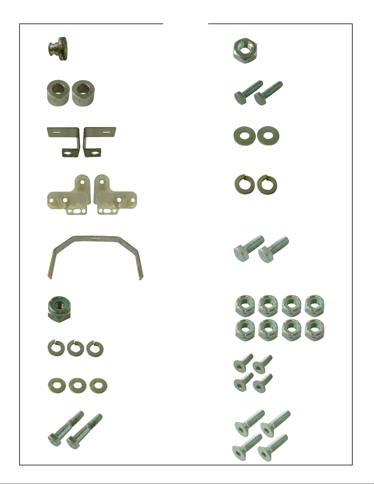
FBI101 SEAT BOLT STUD (1)
PARTS
1/4-20 NUT (1)
FBI102 SHOCK SPACER (2)
FBI205 SADDLE BAG BRACKET (2)
FBI100 FENDER STRUT BRACKET (2)
FBI401 FENDER BRACE (1)
5/16-18X1” HEX CAP (2)
5/16” FLAT WASHERS (2)
5/16” LOCK WASHERS (2)
1/4-20X1” HEX CAP SCREWS
1/4-20 LOCK NUT (1)
1/4” LOCK WASHERS (3)
1/4” FLAT WASHER (3)
1/2-13X2 3/4” HEX CAP SCREWS (2)
5/16” LOCK NUTS (8)
5/16-18X1 1/4” FHCS (4)
5/16-18 1” FHCS (4)
Page 4
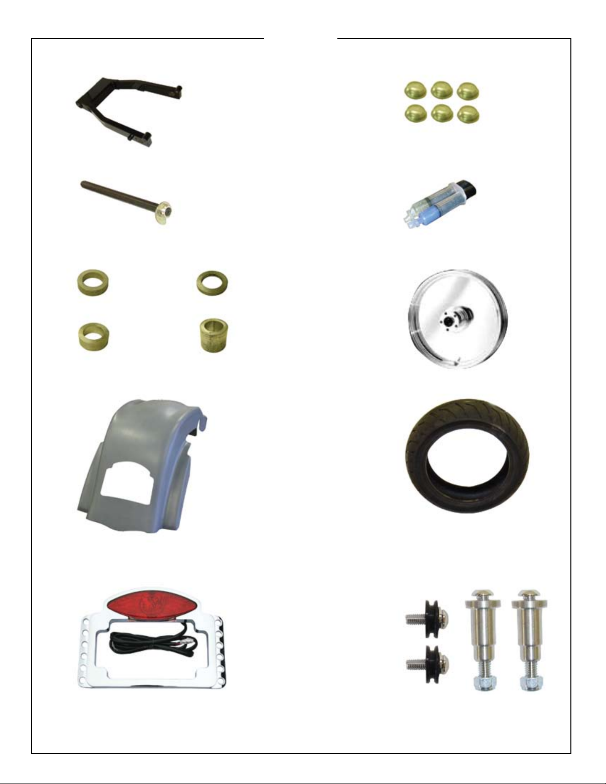
PARTS
FBI650L SWINGARM (1)
FBI150 AXLE (1)
FBI151 WHEEL SPACERS (VARIES FOR ALL
CUSTOM WHEELS)
WHEEL SPACER INCLUDED IN YOUR KIT
FBI151RC USE
WITH RC WHEELS
CALL WITH WHEEL BRAND IF YOU WANT
FBI151WB USE
WITH WELD WHEELS
RUBBER BUMPERS (6)
EPOXY (1)
FBI800-17 SMOOTHIE CHROME WHEEL
FBI151PM USE
WITH PM WHEELS
FBI151WP USE
WITH WELD WHEELS
FBI851 WIDE REAR FENDER (1)
FBI860 TAILLIGHT (1)
200MM TIRE
FBI105 STAINLESS STEEL BACKREST
MOUNTING HARDWARE
Page 5
641-774-7499
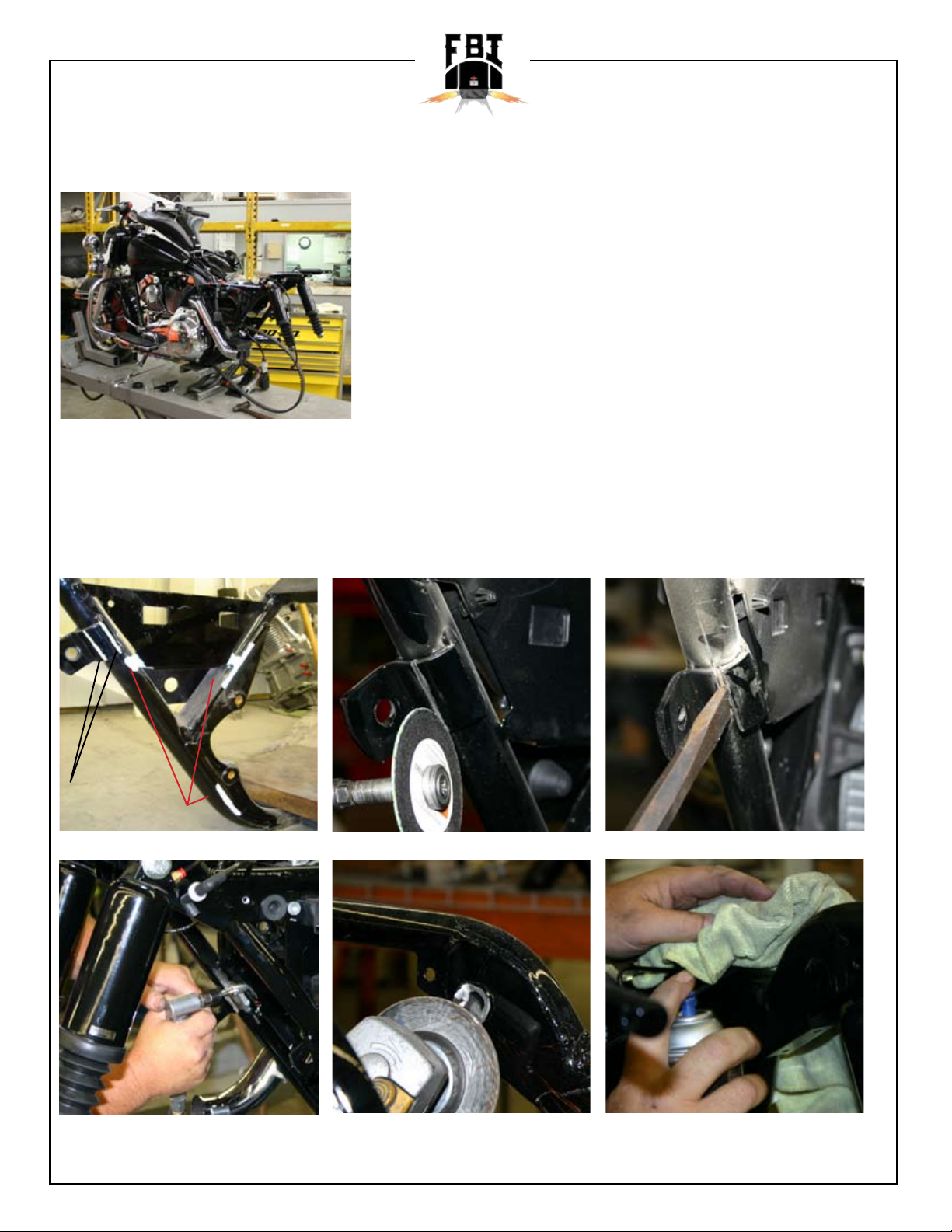
1. Disconnect the battery before starting any of the installation process. Then remove saddle bags,
seat, rear fender, rear wheel, swing arm, side covers, and exhaust system.
2. Locate the left side saddlebag frame rail that is welded to the frame, use a cut off wheel to cut
vertically in between the two welds, and cut through the inside weld. Making sure not to cut into
frame tube. Use chisel and hammer to knock inside of mounting tab off. Grind the remaining weld
off the inside of the frame tube. You must also grind welds down were belt passes through and
inside of the frame and the excessive material where the shocks mounts through the inside of the
frame for belt and tire clearance (see Image A) use touch up paint to cover any bare metal.
www.fatbaggers.com
CUT LINES
GRIND LINES
Image A
Grinding welds for belt
clearance.
Cutting part of mounting tab.
Grinding shock mounts for tire
clearance.
Removing part of mounting tab.
Use touch up paint to cover all
bare metal.
Page 6
641-774-7499
3. Now you are ready to install the new swing arm, all the bearings and bushing are already installed
in the swing arm. Reinstall the swing arm just like it was a stock motorcycle, after installing the
swing arm you will be ready to install the shock spacers.
www.fatbaggers.com
Reinstall swingarm pivot.
Reinstall
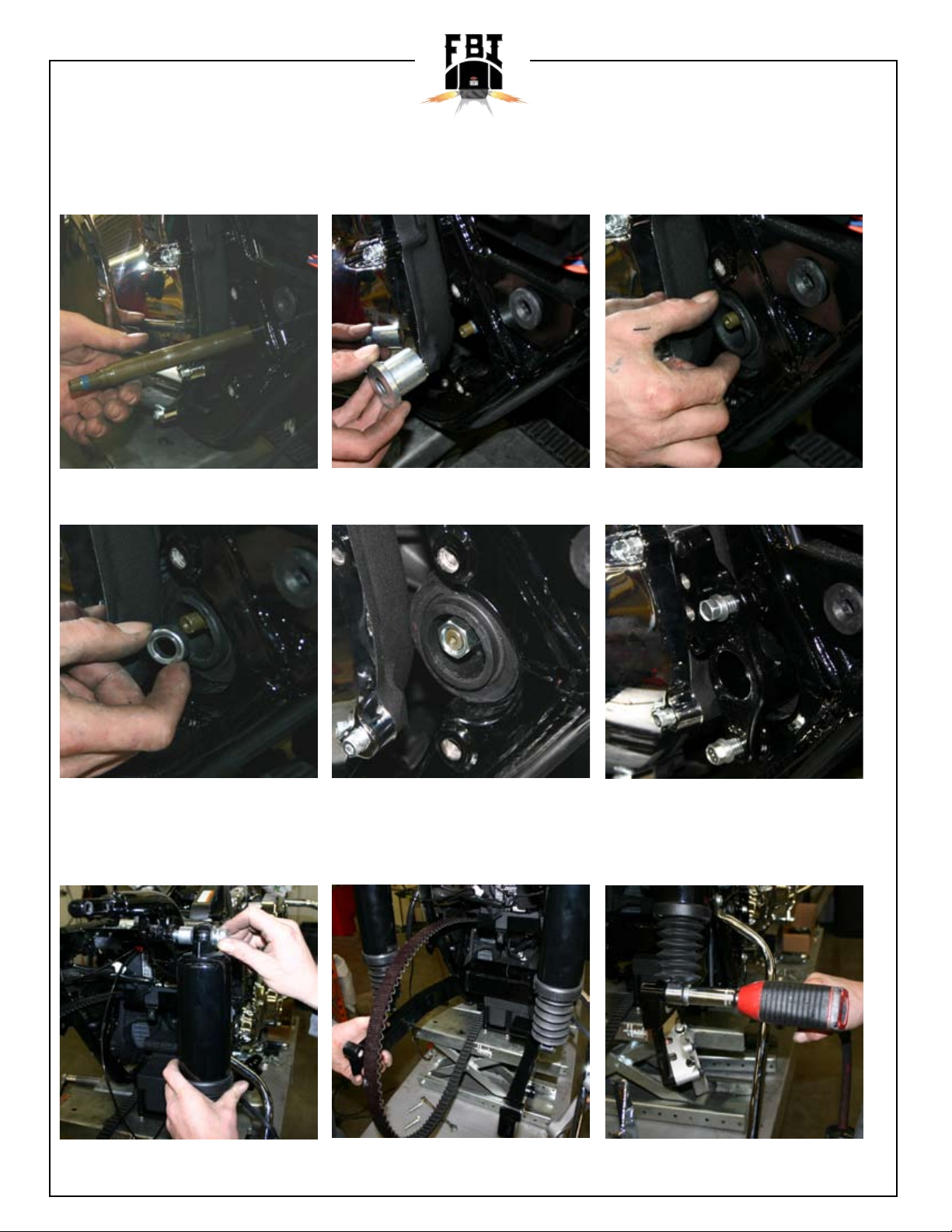
4. You will reuse the stock shock bolts for the bottom of the shocks, for the top of the shocks you will
use the new 1/2” x 13 x 2 3/4 long shock bolts, with 5/8 inches shock spacers FBI102.
Reinstall
Reinstall
Reinstall
Reinstall
Reinstall shock and shock
spacer.
Reinstall new swingarm.
Tighten down shocks to new
swingarm.
Page 7

641-774-7499
www.fatbaggers.com
Backside view of shocks bolted
Reattach air lines for shocks.
to new swingarm.
5. The spacers install between shocks and frame to space out shocks reuse washer from top stock
shock bolts. Now you can install the new fender strut brackets part FBI100 use 5/16x 1 ¼ at head
allen in the top to holes that go through frame with 5/16 lock nuts, use 5/16x1 allens in the bottom
two holes of bracket with 5/16x1 at head allens.
New fender strut brackets
5/16 Lock Nut
FBI100
Image B
5/16 1x1/4” FHCS
5 1/4x1” FHCS
FBI205
installed.
6. Replace rear saddlebag mounting brackets with new saddlebag mounting brackets.
New saddlebag bracket. Slide on gold clip to new bracket.
Reuse gold saddlebag clip.
Page 8

641-774-7499
8. First you are going to start by removing quick release receptacle from rear saddle bag mounting
brackets, and install them on the new FBI200 mounting bracket.
www.fatbaggers.com
New saddlebag bracket.
7. Now we need to mock up saddles bags and backrest hardware, for adjustment.
Saddlebag mock up. Saddlebag mock up. Backrest mock up.
10. With FBI205 mounting, in place leave loose for adjusting saddlebags.
Reuse gold saddlebag clip.
Saddlebag adjusting. Saddlebag adjusting. Backrest hardware adjusting.
Page 9

641-774-7499
11. Install front saddle bag mounting brackets (leave loose for adjustments).
Leave loose for adjusting.
12. Put side cover back on the motorcycle.
www.fatbaggers.com
13. Reinstall saddlebags.
Installing saddlebages. Installing saddlebages. Installing saddlebages.
14. Now adjust saddlebags so bags do not rub side cover.
Page 10

641-774-7499
15. Tighten rear mounting bracket, after adjusting the bag into proper position
www.fatbaggers.com
Tighten them down.
brackets into position.
16. Remove saddlebags.
17. Remove front saddlebag mounting bracket.
18. Leave rear saddlebags mounting bracket attached.
19. Loosely install FBI saddle bag support bracket bridge FBI401.
Tighten them down.Getting rear mounting
Leave loose.
FBI401 installed.
Page 11

641-774-7499
20. Install your new FBI105 backrest mounting hardware, if you are going to be running a backrest
for proper placement. Leave rear mounts loose.
Installing rear mounts.
21. Tighten rubber mounts down, and tighten rear mounts down.
www.fatbaggers.com
Tighten the rubber mounts. Tighten down rear mounts.
22. Install backrest.
Installing backrest checking
alignment of mouting hardware.
Page 12

641-774-7499
23. Tighten rear backrest mounting hardware again if there is any adjustment.
24. Now remove and reinstall backrest making sure there is now binding. If there is binding, present loosen your new FBI100 fender strut brackets, pull or push forward and back as needed to make
backrest install smoothly and easily and reinstall fender support brackets bolts.
www.fatbaggers.com
25. Leave rear backrest mount installed, remove front rubber mount. NOTE: You must spread back-
rest apart to t over FBI fender you can pull apart by hand. Be careful installing over painted fender.
26. Drilling frame for fender tment. Use 1/8 drill bit to drill through frame where front backrest
rubber mount bolt is located, go through threaded hole, drilling through inside of frame, repeat on
other side.
27. With 3/16 drill bit go through the hole where the front saddlebags support bracket was located.
And start drilling through the inside of the frame.
Page 13

641-774-7499
28. Slide fender into place.
If fender is already paint
becareful not to scratch fender.
29. Use palm tap fender down, making sure that fender is tight down against frame struts.
www.fatbaggers.com
Make sure fender is tight
against frame struts.
30. Stand few feet behind motorcycle, sight down the top of fender to top the gas tank to make sure
fender is sitting level on motorcycle.
31. Once you have the fender positioned properly use right angle drill, to drill through holes that you
previously drilled. Drill from the inside of the frame out with fender in place, use 1/8 drill bit.
Page 14

641-774-7499
32. Remove fender
33. Drill pilot holes out with a 21/64 drill bit.
www.fatbaggers.com
Drilling pilot holes. Use a 21-64
drill bit.
34. Before painting fender, install part# FBI101, into fender for mounting a two up seat, the fender
has marked indentation on fender where you need to drill use drill bit. Use plastic clip off of factory
seat to hold in place FBI101, then you can berglass or epoxy the seat bolt stud to fender on
berglass. If you received a painted fender this step has already been done for you.
Fiberglassed seat bolt
installed.
35. Now your fender is ready for painting, after fender is painted you are ready to install FBI860.
Turn fender upside down on something soft. Use a 60 second epoxy (is included) to install the
taillight. With fender upside down place taillight into hole, use cardboard shims to shim taillight until
it is ush with outside of fender, then apply 60 second epoxy through the holes on each side of
taillight. We recommend scufng the inside of fender, so the epoxy with properly adhere to inside of
fender. Then use RVT silicon go around taillight to water tight taillight to fender. Then place wiring
into clips on inside of fender. NOTE: Use instructions provided with FBI860 for wiring 2008 bikes
have to have wire placed different in the plug. Too wire the taillight take the white connector, and
take slot 4 and 5 and reverse them so that 4 will now be 5 and 5 will now be 4.
Drilling pilot holes.
Seat bolt in position.
Page 15

641-774-7499
www.fatbaggers.com
Locate wires. Remove wires and change
there positions.
Tape down FBI860 for epoxy it
into place. Epoxy sets up in 60
seconds.
36. Reinstall fender.
Taped areas are areas we
recommend that you epoxy.
Do not use tape that is for
showing you where to epoxy.
Plug wires back into position.
Finished silicon look. Silicon
needs to dry.
Installing rear fender.
Page 16

641-774-7499
37. Loosely install front saddle bag mounting brackets using shims as needed inside, in between
fender and frame to insure you will not crack fender when you tighten down. This can be done with
washers.
www.fatbaggers.com
Sliding shim into place to
prevent fender from cracking.
38. Reinstall saddlebags attach to rear saddlebag brackets rst.
Reinstalling saddlebags. Reinstalling saddlebags. Reinstalling saddlebags.
40. Install front saddlebag pin then tighten front saddlebag mount.
Reusing front saddlebag
mount.
Reinstalling saddlebags. Reinstalling saddlebags. Reinstalling saddlebags.
Page 17

641-774-7499
41. Make stud go through slot in center of saddlebag support bracket bridge FBI401.
Fender stud through FBI401.
43. Put ¼ inch lock nut on stud sandwiching the bridge. Leave loose.
www.fatbaggers.com
1/4 lock nut on stud.
44. Center fender in between saddlebags when fender is in center position tighten ¼ inch lock nut on
stud locking bottom of fender into place.
Getting fender centered into
position.
Tighten down 1/4 lock nut to
hold fender in position.
Page 18

641-774-7499
45. Now install 3 rubber bumpers on ller strips as show in g this will prevent saddlebags coming
contact with fender.
Rubber bumpers installed on
rear fender.
46. Before installing the rear wheel, you will need to remove the 08” pulley and bolts from the
wheel. This is where you need to install the 2008 Upgrade Kit pulley and bolts for proper tment.
www.fatbaggers.com
Install 2008 Upgrade Kit pulley
and pulley bolts.
46.5 Remove saddlebag again. Install rear wheel, with sprocket on, rotor off. NOTE: If using 17
inch rim, you must grind corner of caliper off to make sure it does not contact rim.
Slide wheel into position. Wheel in position and ready for
rear axle to be installed.
Page 19

641-774-7499
www.fatbaggers.com
Grinding caliper so it does not
Finished grinding caliper.
contact the rim and damage it.
47. Refer to chart for wheel spacing.
2007
Sprocket
Side #1
1.490
RC
FBI151RCP
PM
STOCK
WELD
1.3”
HD106002
STOCK
STOCK
Pulley
Spacer
Side #2
.125
Inbetween
Hub and
Caliper #3
STOCK
STOCK
STOCK
Between
Caliper and
Swingarm #4
.475
FBI151RC
.530
.190
Image F
#1
#2
#3
#4
DRIVE PULLEY
Tire
BRAKE CALIPER
Swingarm
48. Install rear wheel axle half way through wheel, go to caliper side, install caliper and rotor at the
same time, and tighten one of the rotor bolts. Use stock spacers in between hub and brake
caliper, use supplied spacer in between brake caliper and swing arm. NOTE: Spacers vary with
wheel manufacturer.
Sliding axle through swingarm. Axle coming through hub on
right side.
Lining up rotor and caliper for
axle to slide through.
Page 20

641-774-7499
49. Slide axle through, tighten belt and torque axle nut to manufactured specications.
50. Install remaining rotor bolts. Reinstall exhaust pipes saddlebags seat, side cover.
www.fatbaggers.com
Tighten down last rotor bolts. Exhaust system installed. Installing sidecovers.
Installing saddlebags. Finished Look!
 Loading...