

Page 1

NM350
Network Switch
User
Manual
Revision 1.4
December 2015
The product described in this manual is compliant
with all related CE standards.
Page 2

Product Title: NM350
Document name: NM350 User Manual
Manual version: 1.4
Copyright © 2016 Fastwel Co. Ltd. All rights reserved.
Revision Record
Revision No
Brief description of changes
Board index
Revision date
1.0
Initial version
NM350
June 2014
1.1
MTBF value has been revised (subsection 1.1) and
adjusted value of warranty period was provided.
Adjustment of subsection 1.3
(delivery checklist).
NM350
May 2015
1.2
Second version with a set of mating parts was added:
NМ350-02 – 2 LAN 1000 Mb/sec, 4 LAN 10/100/1000
Mb/sec with PoE, power supply from 9 V to 36 V, set of
connector mating parts. Table 4-4 was added. Figure 24 was changed.
Adjustment of delivery checklist.
NM350
June 2015
1.3
Change of the number of sets of mating parts of LAN
connectors of NМ350-02 version.
NM350
November 2015
1.4
Compliance assessment
NM350
December 2015
Contact information
Fastwel Co. Ltd
Fastwel Corporation US
Address:
108 Profsoyuznaya st.,
Moscow 117437,
Russian Federation
6108 Avenida Encinas,
Suite B, Carlsbad,
CA92011, USA
Tel.:
+7 (495) 232-1681 Tel.:
+1 (858) 488-3663
Fax:
+7 (495) 232-1654
Page 3

N M 3 5 0
NM350 USER MANUAL
© 2 0 1 6
3
Table of contents
Contact information ......................................................................................................................................... 2
-
Table of contents ……………………………………………………………………………………………………………. 3
List of tables…………………………………………………………………………………………………………………. 4
List of figures………………………………………………………………………………………………………………… 4
Trademarks………………………………………………………………………………………………………………….. 5
Ownership Rights…………………………………………………………………………………………………………… 5
Notation Conventions……………………………………………………………………………………………………….. 5
Safety Requirements………………………………………………………………………………………………………… 6
High Voltage Safe Handling Rules………………………………………………………………………………… 6
General Board Operation Rules……………………………………………………………………………………………. 6
MANUFACTURER'S WARRANTIES………………………………………………………………………………………. 7
1
Introduction…………………………………………………………………………………………………….. 8
1.1 Main features of NM350 ............................................................................................................................... 8
1.2 NM350 ordering information ......................................................................................................................... 9
1.3 Delivery checklist of NM350.......................................................................................................................... 9
1.4 Packaging information ................................................................................................................................ 10
1.5 External view and location of components……………………………………………………………………….. 10
1.5.1 Location of main components and dimensions of NM350.......................................................... 11
2
Functional description………………………………………………………………………………………..12
2.1 Board layout................................................................................................................................................ 12
2.2 Specifics of functional nodes operation……………………………………………………………………………12
2.3 Device interfaces ........................................................................................................................................ 13
2.3.1 Gigabit Ethernet interface with PoE ........................................................................................... 13
2.3.1.1 Purpose of LAN connector contacts………………………………………………………20
2.3.1.2 LED indication of Ethernet channels state and power supply ................................... 14
2.3.1.3 PoE power supply ..................................................................................................... 15
A. Control in Linux 2.6 OS…………………………………………………………………………16
B. Control in QNX 6.5 ......................................................................................................... 16
C. Control in Windows XP (Embedded)………………………………………………………….18
3
Installation ............................................................................................................................................ 19
3.1 Safety Requirements………………………………………………………………………………………………..19
3.2 Installation methods…………………………………………………………………………………………………19
4
Additional information ........................................................................................................................ 20
4.1 Power consumption of NM350 .................................................................................................................... 20
4.2 Compliance with safety requirements…………………………………………………………………………….. 20
4.3 Noise resistance of NM350………………………………………………………………………………………… 20
4.4 Operation conditions…………………………………………………………………………………………………20
4.5 Malfunctions and their troubleshooting methods………………………………………………………………… 21
5
Transportation, unpacking and storage………………………………………………………………… 22
5.1 Transportation............................................................................................................................................. 22
5.2 Unpacking ................................................................................................................................................... 22
5.3 Storage ....................................................................................................................................................... 22
Page 4

N M 3 5 0
NM350 USER MANUAL
© 2 0 1 6
4
List of tables
Table 1-1: Components of NM350 depending on device version ................................................................. 9
Table 2-1: Purpose of LAN connector contacts………………………………………………………………………..14
Table 2-2: Interpretation of the front panel notations ................................................................................ 14
Table 2-3: Purpose of XP6 connector contacts ........................................................................................ 16
Table 4-1: Power supply voltage range of NM350…………………………………………………………………….20
Table 4-2: NM350 consumption current………………………………………………………………………………...20
Table 4-3: Parameters of climatic and mechanical effects……………………………………………………………21
Table 4-4: Typical malfunctions and their troubleshooting methods…………………………………………………21
List of figures
Fig. 1-1: Location of main components and dimensions of NM350……………………………………….……...11
Fig. 2-1: NM350 board layout…………………………………………………………………………………….…...12
Fig. 2-2: External view of LAN connector………………………………………………………………………….…13
Fig. 2-3: External view of the front panel LEDs ...................................................................................... 14
Fig. 2-4: Dependence of the maximum total load to all ports on temperature conditions ............................ 15
Fig. 2-5: Description of the dialog box of operation with PoE .................................................................. 18
All information in this document is provided for reference only, with no warranty of its suitability for any specific purpose. This information has been
thoroughly checked and is believed to be entirely reliable and consistent with the product that it describes. However, Fastwel accepts no responsibility for
inaccuracies, omissions or their consequences, as well as liability arising from the use or application of any product or example described in this document.
Fastwel Co. Ltd. reserves the right to change, modify, and improve this document or the products described in it, at Fastwel's discretion without
further notice. Software described in this document is provided on an “as is” basis without warranty. Fastwel assumes no liability for consequential or incidental
damages originated by the use of this software.
This document contains information, which is property of Fastwel Co. Ltd. It is not allowed to reproduce it or transmit by any means, to translate the
document or to convert it to any electronic form in full or in parts without antecedent written approval of Fastwel Co. Ltd. or one of its officially authorized agents.
Fastwel and Fastwel logo are trademarks owned by Fastwel Co. Ltd., Moscow, Russian Federation. Ethernet is a registered trademark of Xerox
Corporation. IEEE is a registered trademark of the Institute of Electrical and Electronics Engineers Inc. Intel is a trademark of Intel Corporation. Pentium M and
Celeron M are trademarks of Intel Corporation. Microsoft is a trademark of the Microsoft corporation. In addition, this document may include names, company
logos and trademarks, which are registered trademarks and, therefore, are property of their respective owners.
Fastwel welcomes suggestions, remarks and proposals regarding the form and the content of this Manual.
Page 5

N M 3 5 0
NM350 USER MANUAL
© 2 0 1 6
5
Trademarks
"Fastwel" logotype is a trademark belonging to Fastwel Group Co. Ltd., Moscow, Russian
Federation.
Besides, this document may contain names, corporate logotypes and trademarks being
registered trademarks; consequently, property rights to them belong to their respective legitimate
owners.
Ownership Rights
This document contains information being the property of Fastwel Group Co. Ltd. It can
neither be copied nor transferred with the utilization of known media nor be stored in data storage
and search systems without the prior written authorization of Fastwel Group Co. Ltd. To our best
knowledge, the data in this document does not contain errors. However, Fastwel Group Co. Ltd
cannot take responsibility for any inaccuracies and their consequences, as well as responsibility
arising as a result of utilization or application of any diagram, product or example cited in this
document. Fastwel Group Co. Ltd reserves the right to alter and update both this document and
the product presented therein at its own discretion without additional notification.
Notation Conventions
Warning!
Information marked by this symbol is essential for human and
equipment safety.
Read this information attentively, be watchful.
Note
This symbol and title marks important information to be read attentively for
your own benefit.
Page 6

N M 3 5 0
NM350 USER MANUAL
© 2 0 1 6
6
Safety requirements
This product is designed and tested for the purpose of ensuring compliance with the electric
safety requirements. Its design guarantees long-term failsafe operation. Life cycle of the device
can be sufficiently reduced due to improper handling during unpacking and installation. Therefore,
for your own safety and in order to ensure the proper operation of the device, you should observe
the below recommendations.
High Voltage Safe Handling Rules
Warning!
All the works that involve this device should be carried out by the
appropriately qualified personnel.
Warning, high voltage!
Before installing the board into the system, make sure that the mains
supply is switched off.
During installation, repairs and maintenance of the device there is a
real danger of exposure to electric shock, therefore you should
always disconnect the power supply feeding cable from the socket at
the time of works. This also applies to the other power supply
feeding cables.
General Board Operation Rules
To keep the warranty, the product should not be altered or revised in any way. Any
alterations or improvements not authorized by Fastwel LLC, except for those specified
in this document or obtained from the technical support department of Fastwel LLC as
a set of instructions for their implementation, cancel the warranty.
This device should be installed and connected only to the systems, meeting all the
necessary technical and climatic requirements.
While performing all the required operations for installation and adjustment, please
follow the instructions specified only in this document.
Keep the original package for subsequent storage of the device and transportation in
the warranty event. If it is necessary to transport or store the board, please pack it
the same way as it was packed upon delivery.
Exercise special care when unpacking and handling the device. Act in accordance with
the instructions given above and in the paragraph 5 Transportation, unpacking and
storage.
Do not leave the board without protective packaging, when it is not operated.
Page 7

N M 3 5 0
NM350 USER MANUAL
© 2 0 1 6
7
MANUFACTURER'S WARRANTIES
Warranty liabilities
The manufacturer guarantees that device's quality corresponds to the requirements of
technical specification TU 465275.001 provided that the Consumer meets operation, storage,
transportation and installation conditions and procedures, specified by accompanying documents.
The Manufacturer hereby guarantees that the products supplied thereby are free from
defects in workmanship and materials, provided operation and maintenance norms were observed
during the currently established warranty period. The Manufacturer's obligation under this warranty
is to repair or replace free of charge any defective electronic component being a part of a returned
product.
Products that broke down through the Manufacturer's fault during the warranty period will be
repaired free of charge. Otherwise the Consumer will be invoiced as per the current labor
remuneration rates and expendable materials cost.
Liability limitation right
The Manufacturer shall not be liable for the damage inflicted to the Consumer's property
because of the product breakdown in the process of its utilization.
Warranty period
The warranty period for the products made by Fastwel LLC is 24 months since the sale date
(unless otherwise provided by the supply contract).
The warranty period for the custom-made products is 36 months from the date the Product
was fist purchased (unless otherwise provided by the supply contract).
Limitation of warranty obligations
The above warranty obligations shall not be applied:
To the products (including software), which were repaired or were modified by the
employees, that do not represent the manufacturer. Exceptions are the cases where the
customer has made repairs or made modifications to the devices in the strict compliance with
instructions, preliminary agreed and approved by the manufacturer in writing;
To the products, broken down due to unacceptable polarity reversal (to the opposite sign)
of the power supply, improper operation, transportation, storage, installation, mounting or
accident.
Procedure of device returning for repairs
Sequence of activities when returning the products for repairs:
Apply to Fastwel company or to any of the Fastwel's official representatives for the Product
Return Authorization;
Attach a failure inspection report with a product to be returned in the form, accepted by
the Manufacturer, with a description of the failure circumstances and symptoms;
Carefully package the product in the manufacturer's antistatic bag (carton box), in which
the product had been supplied. Failure to package in antistatic material will unilaterally VOID
all warranties.
The customer pays for shipping the product to Fastwel or to an official Fastwel
representative or dealer.
Page 8

NM350 USER MANUAL
© 2 0 1 6
8
N M 3 5 0
Introducti
1 Introduction
NM350 network switch represents a finished product equipped with six Ethernet channels,
designed for the use in data collection and processing systems, operating in harsh environments
and based on Gigabit Ethernet interface with a possibility to connect of up to 4 user devices with
support of PoE (Power over Ethernet) technology of power supply transfer over Ethernet data
transmission lines.
The device is supplied with power via D-Sub front connector using an integrated voltage
converter. If there are no connected devices, the board dissipates less than 9 W, which makes it
possible not to use additional external cooling.
Stability of NM350 network switch operation enables to use it in all industrial applications.
Components used as the basis for NM350, are carefully selected following applicability criteria in
embedded systems, which makes the module an optimal solution for the systems with a long life
cycle.
The User Manual contains directions for a proper and safe installation, powering-on and
configuration, connection and interaction of NM350 with external devices.
For proper operation of the module within the specified service life it is required to previously
look through the contents of this User Manual.
1.1 Main features of NM350
Switch:
Second level of OSI model;
4x 10/100/1000Base-T channels;
2x 1000Base-T channels;
Automatic setting a connection through all the ports (auto-negotiation);
1 Mb of the memory dynamic buffer;
Table for 8 000 MAC addresses with automatic learning and aging;
Compliance with the 802.3az Energy Efficient Ethernet standard;
PoE PSE controller:
Compliance with the IEEE 802.3af standard;
Output power to the port: up to 15.4 W;
Power supply by A method;
PoE hardware monitor:
Outputs in D-Sub connector for the connection of external control and management
device over the insulated SMBus;
Insulation voltage 1500 V;
Indication:
LED for indication of the switch power supply connection;
LEDs of connection and activity at ports (ACT);
LEDs of ports connection to Gigabit Ethernet (Gbit);
LEDs of detection and PoE power supply of the devices over each of the ports.
Page 9

NM350 USER MANUAL
© 2 0 1 6
9
N M 3 5 0
Introducti
Weight, not more than:
1.4 kg
Dimensions, no more than:
171 mm × 139 mm х 82 mm.
Power supply voltage:
from +9 V to +36 V
Maximum power consumption, not including external devices
9 W.
MTBF, not less than:
170 000 hours
PoE control libraries for OS:
Windows XP (Embedded);
Linux 2.6;
QNX 6.5.
1.2 NM350 ordering information
Notations (ordering information) in Fastwel product catalogs are given in Table 1-1.
Table 1-1: Components of NM350 depending on device version
Name
Convention
al
Ordering
designation
Note
Network switch
NM350
NM350
NM350-01
4 LAN 10/100/1000 Mb/sec with PoE,
2 x LAN 1000 Mb/sec
NM350-02
4 x LAN 10/100/1000 Mb/sec with PoE,
2 x LAN 1000 Mb/sec, a set of mating
parts of connectors
1.3 Delivery checklist of NM350
Delivery checklist of NM350 includes:
1. NM350 device – 1 pcs.;
2. IMES.465921.001 Installation kit (panel fixing) – 1 pcs.;
IMES.745532.014 Mounting bracket – 1 pcs.;
Screw М4х8 DIN7985 – 4 pcs.;
Lock washer M4 DIN25201 – 4 pcs.;
3. IMES.465921.002 Installation kit (DIN-rail mounting) – 1 pcs.;
UTA 130 mounting rail adapter p/n 2706412 Phoenix contact – 1 pcs.;
Screw М3х8 DIN7985 – 4 pcs.;
Lock washer Ø3.2 DIN125 – 4 pcs.;
4. IMES.465921.003 Installation kit – 1 pcs.;
Cap p/n 21 01 000 0003 Harting – 6 pcs.;
Backshell p/n 09 67 015 0417 Harting – 1 pcs.;
Page 10

NM350 USER MANUAL
© 2 0 1 6
10
N M 3 5 0
Introducti
Screw М4х8 DIN7985 – 1 pcs.;
IMES.758441.004 Nut – 1 pcs.;
5. For NM350-02 version, the delivery checklist includes IMES.465921.005
assembly kit:
6x kits of mating parts of LAN connectors, which include:
М12 connector, p/n 21 03 881 1805 Harting – 1 pcs.;
M12 contact, p/n 21 01 100 9014 Harting – 8 pcs.;
1x kit of mating parts of PWR connectors:
IP67 D-SUB Backshell, p/n 09 67 015 0538 Harting – 1 pcs.;
Cable socket, p/n 09 69 201 7072 Harting – 1 pcs.;
Power contacts, p/n 09 69 181 7420 Harting – 2 pcs.;
6. Technical Certificate;
7. Packaging.
Note
As an extra, user can order mating connectors as accessories, if
applicable:
LAN - ASC00066: Harting p/n: 21 03 881 1805 – 1 pcs.;
Harting p/n: 21 01 100 9014 – 8 pcs.;
PWR - ASC00066-01: Harting p/n: 09 67 015 0538 – 1 pcs.;
Harting p/n: 09 69 201 7072 – 1 pcs.;
Harting p/n: 09 69 181 7420 - 2 pcs.
1.4 Packaging information
NM350 is packaged in a box, which has the following overall dimensions: 210 x 160 x 160
mm. Packaged weight of the module is not more than 2 kg.
Note
Retain the original antistatic and consumer packages of the module
till the end of the guarantee service life period.
1.5 External view and location of components
The below figures will help you identify components, their configuration and functions.
Page 11
NM350 USER MANUAL
© 2 0 1 6
11
N M 3 5 0
Introducti
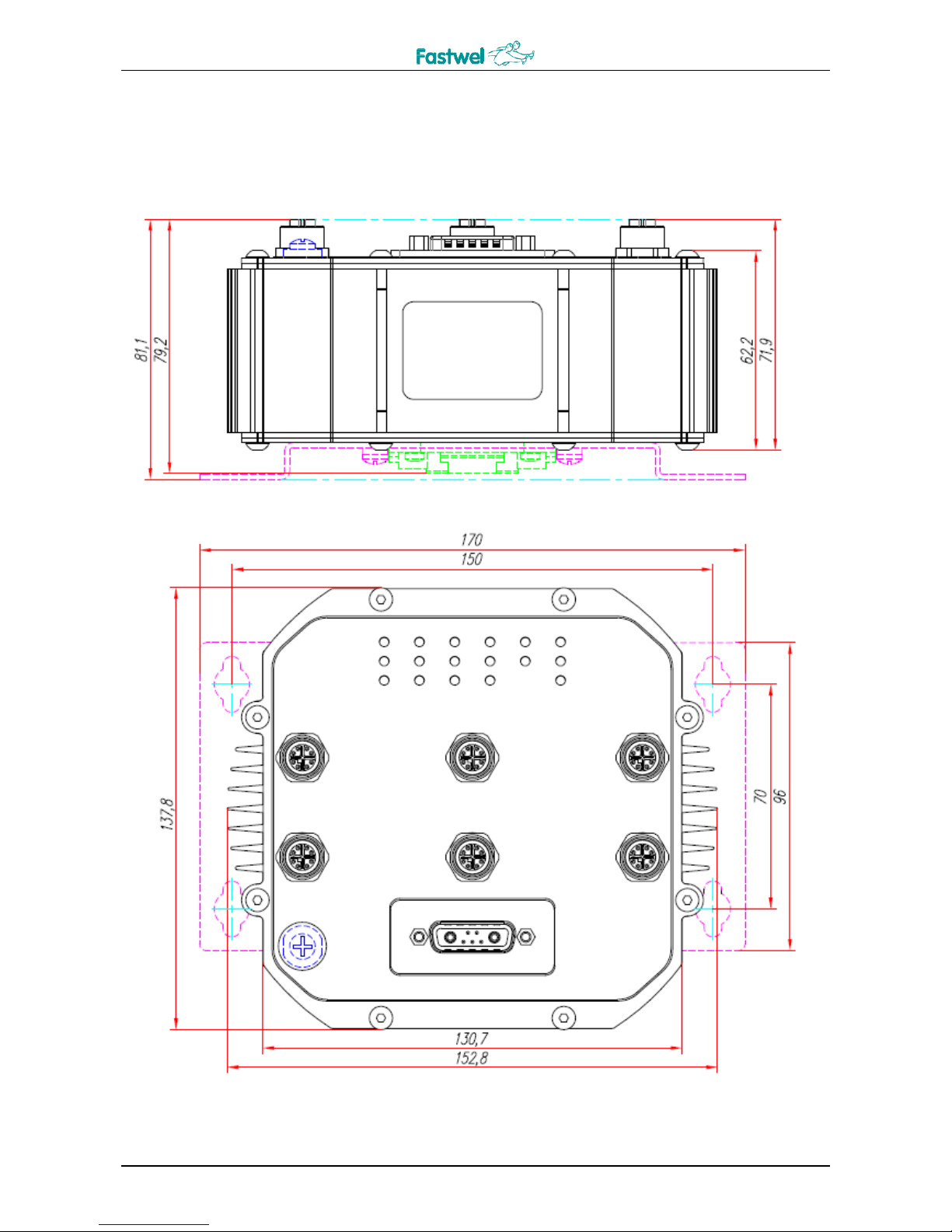
1.5.1 Location of main components and dimensions of NM350
Location of connectors and main components of the device with specification of
overall dimensions is given in Fig.
Fig. 1-1: Location of main components and dimensions of NM350
Page 12
NM350 USER MANUAL
© 2 0 1 6
12
N M 3 5 0
Functional description
6 x LAN + 4 xPoE
MC07
2 Functional description
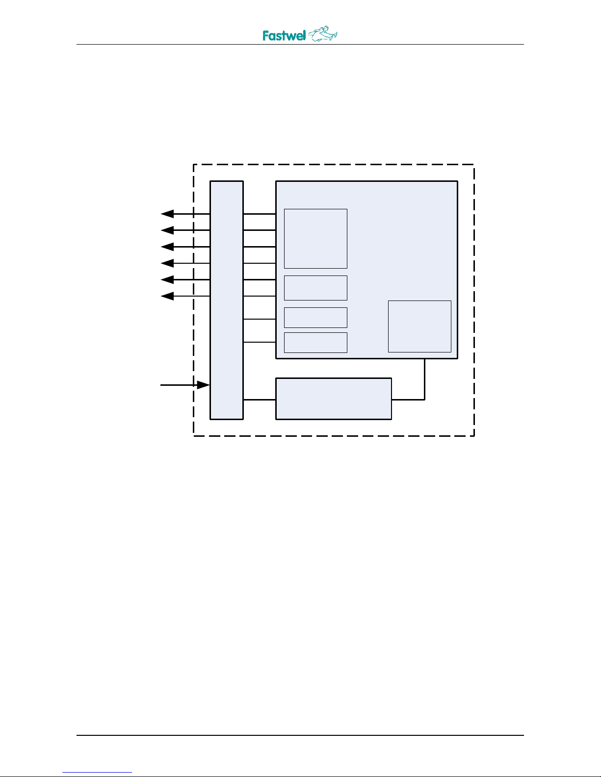
2.1 Board layout
NIM354
4 x 10/100/
1000
Ethernet +
PoE
2 x 1000
Ethernet
LED’s
DC/DC
48V - 5V
SMBus
+9...36 V
SMBus
Fig. 2-1: NM350 board layout
MIP17
NM350 contains the following main functional modules:
NIM354-03 network module;
MIP17 power supply source module;
MC07 switching module.
2.2 Specifics of functional nodes operation
NIM354-03
NIM354 network switch module is designed for the use in embedded data collection and
processing systems, operating in harsh environments and based on Gigabit Ethernet interface with
a possibility of connection up to four devices with PoE (Power over Ethernet) support.
4 x LAN 10/100/1000 Mb/sec ports with PoE;
2x LAN 1000 Mb/sec ports;
Power supply range from 36 V to 57 V;
Page 13
NM350 USER MANUAL
© 2 0 1 6
13
N M 3 5 0
Functional description
PoE control bus over SMBus.
MIP17
MIP17 power supply source module is designed for the use as part of the devices generating PoE
(PSE) power supply.
Input power supply range from 9 V to 36 V;
Output voltage 48 V ± 5 %;
Maximum output power 75 W.
MC07
Module for switching of Ethernet-interfaces of NIM354-03 to external sealed М12 connectors,
SMBus interface with high-voltage insulation and input power supply to the connector of D-sub
type and output of LED indication.
Power supply
From 9 V up to 36 V from the PWR connector.
2.3 Device interfaces
2.3.1 Gigabit Ethernet interface with PoE
The device has four 10/100/1000 Base-T ports and two 1000 Base-T Ethernet ports routed to
the industrial connectors M12 (LAN1…6). Switching of these ports is carried out on the basis of
Marvell Ethernet Switch 88E6176 and 2x Marvell PHY 88E1510 switches. Controller's architecture
is optimized to achieve high speed switching at minimum power consumption.
For LAN1 - LAN4 ports, the switch ensures automatic determination of transfer rate and
switching between data transfer modes 10Base-T, 100Base-TX and 1000Base-T. Auto-negotiation
MDI/MDIX is activated in all 6 ports.
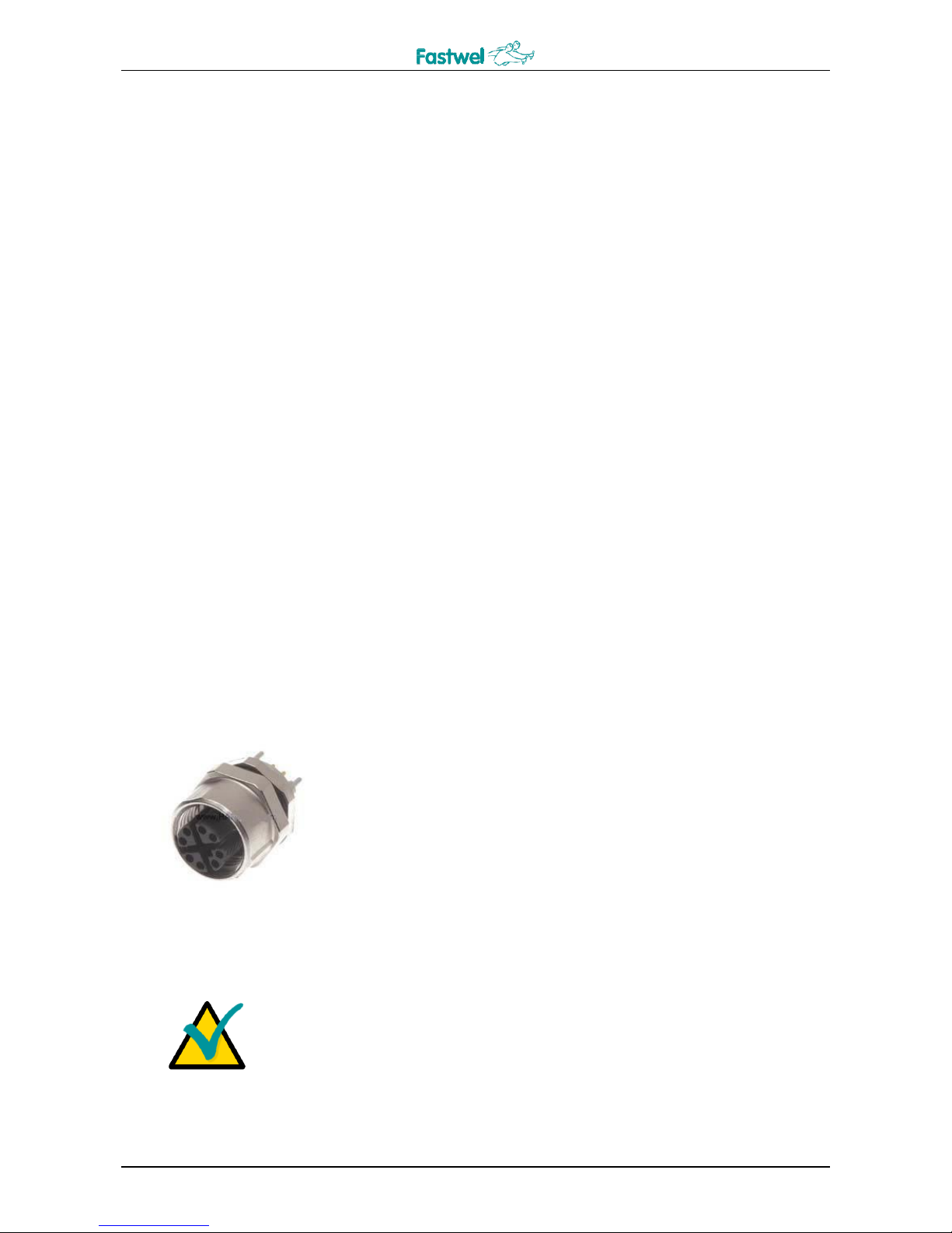
The front panel is equipped with six Gigabit Ethernet ports, which
use this connector type. 4 of them (LAN1, LAN2, LAN3, LAN4) are
supplied with the controlled power supply PoE (see subsection
2.3.1.3).
Fig. 2-2: External view of LAN connector
Note
These connectors ensure device tightness only ready-fitted with
Harting har-speed M12 mating connectors or special plugs, which
are supplied in set with the switch.
Page 14
NM350 USER MANUAL
© 2 0 1 6
14
N M 3 5 0
Functional description
Data transfer standard
PoE power
supply (LAN1
– LAN4)
10Base-T
100Base-TX
1000Base-T
Method A
Optional
I/O
Signal
I/O
Signal
I/O
Signal
1 O TX +
O
TX +
I/O
BI_DA+
DC +
– 2 O
TX –
O
TX –
I/O
BI_DA–
DC +
–
3 I RX +
I
RX +
I/O
BI_DB+
DC –
–
4 I RX –
I
RX –
I/O
BI_DB-
DC –
– 5 –
– – – I/O
BI_DD+
–
DC +
6 – – – – I/O
BI_DD-
–
DC +
7 – – – – I/O
BI_DC-
–
DC –
8 – – – – I/O
BI_DC+
–
DC –
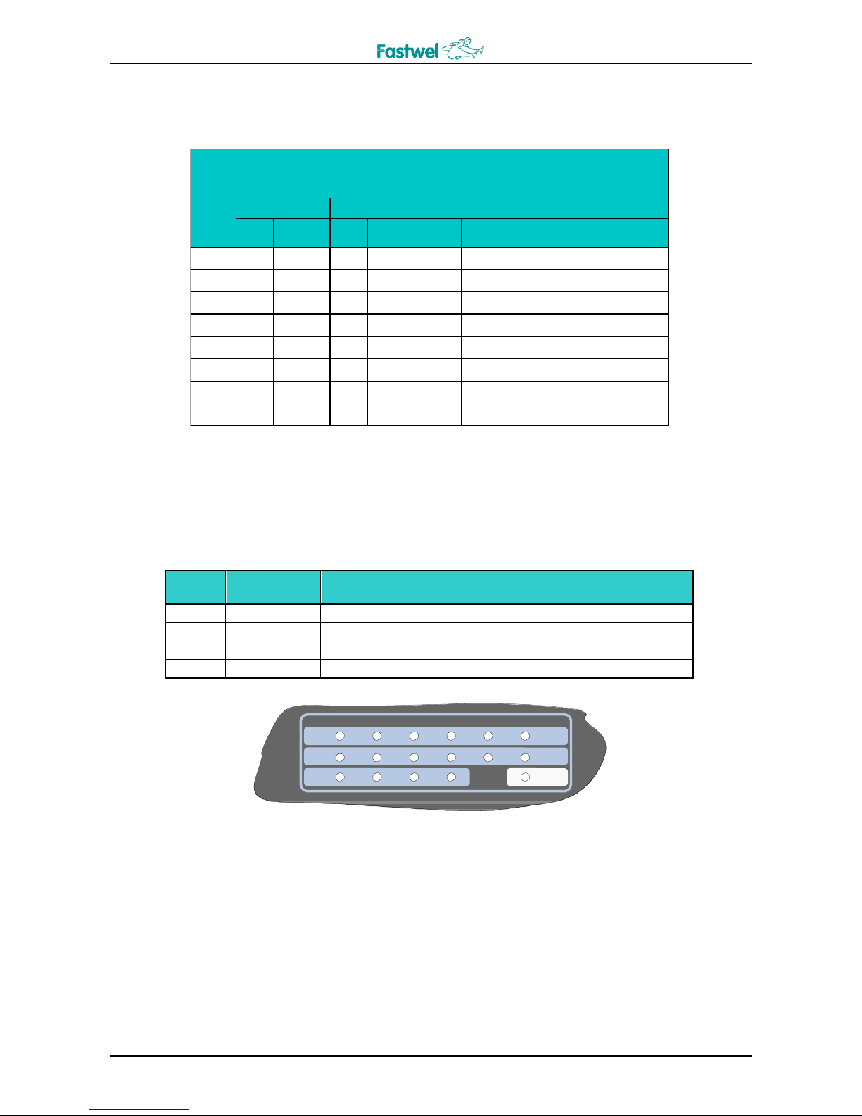
2.3.1.1 Purpose of LAN connector contacts
Table 2-1: Purpose of LAN connector contacts
Contact
Method B
Connection and operation via each Ethernet port of these connectors are respectively shown
through the signals for LEDs at XP5 connector.
Power supply PoE is implemented using the Method A and is described below.
2.3.1.2 LED indication of Ethernet channels state and power supply
Table 2-2: Interpretation of the front panel notations
Name
Port
Purpose
ACT
LAN1 - 6
Connection and activity of Ethernet channel
Gbit
LAN1 - 6
Channel connection in 1000Base-T mode
PoE
LAN1 - 4
Connection and power supply of the external device over
PWR
-
Power supply indicator of the switch
ACT
Gbit
1 2 3 4 5 6
PoE PWR
Fig. 2-3: External view of the front panel LEDs
ACT functionality, Link/Activity – LED is on if there is Ethernet connection on the relevant port
and flashes, if this port is used for receipt and sending of network packages by the switch. Gbit
LED is on when 1000Base-T interface is connected via this port. The relevant port number is
signed on the top of its LEDs. PWR LED indicates that the device is switched on.
Page 15
NM350 USER MANUAL
© 2 0 1 6
15
N M 3 5 0
Functional description
Warning!
For port 5 and 6, Gbit LEDs are on apart from the connection of
1000Base-T, during connection of 100Base-T, but the port itself is
operating only in the 1000Base-T mode.
2.3.1.3 PoE power supply
This technology, together with data, enables the switch to transfer power supply to a remote
device via 2 Ethernet twisted-pair wires in accordance with the IEEE 802.3af standard, using the
method A. This standard allows power supply of devices with the voltage from 44 V to 57 V. The
device supplies power to external devices 48V ± 5%.
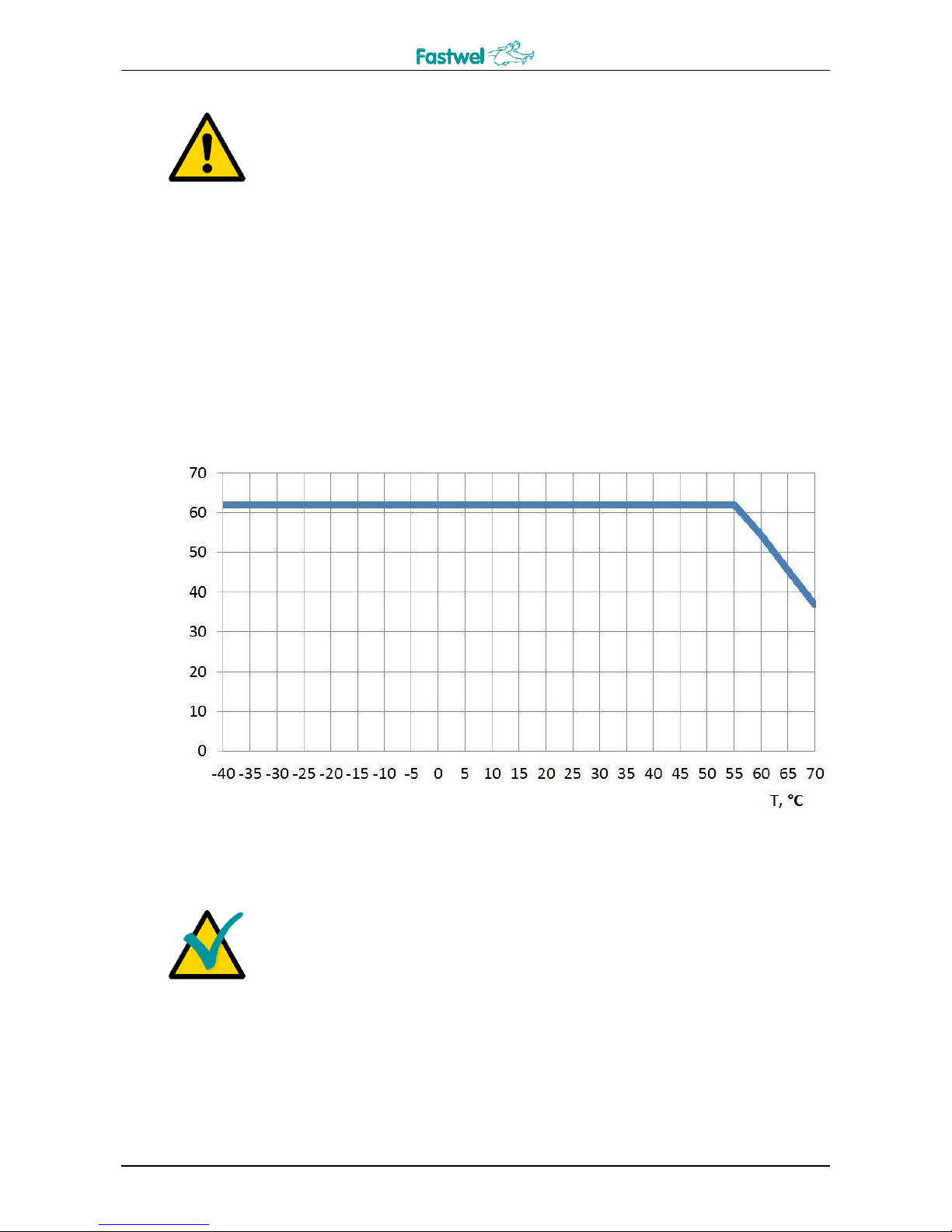
The IEEE 802.3af standard enables connection of 4 classes of devices, including those with
a power up to 15.4 W per channel, therefore a total load to all of the 4x PoE ports can’t exceed 62
W. Dependence of the maximum load on ambient temperature conditions is shown in the diagram
below.
Fig. 2-4: Dependence of the maximum total load to all ports on temperature conditions
Note
When connecting PoE devices with a higher power consumption,
special consideration should be given to the dependence of
maximum total load on ambient temperature, as well as on the
removal of heat from the device.
Operation of PoE microchip of the controller (TPS23841) can be carried out under control of
an external device, connected via an insulated I2C bus / SMBus via PWR connector, which
contacts purpose is described below.
P, W
Page 16

NM350 USER MANUAL
© 2 0 1 6
16
N M 3 5 0
Functional description
Table 2-3: Purpose of XP6 connector contacts
Contact
number
Signal
Purpose
Input/Output
1 - -
-
2 - -
-
3
MDIO
I2C Data
In/Out
4
GND
GND
In
5
MDC
I2C Clock
In
А1
AGND
- U
in
In
А2
Vcc
+ U
in
In
For various operating systems (OS) drivers and utility programs for operation with TPS23841
over I2C bus / SMBus are supplied with CPC309 CPU Module (can be found on Fastwel FTP).
A. Control in Linux 2.6 OS
Control is carried out via write/read from controller registers (for more detailed information
see documentation for TPS23841). PoE.sh script demonstrates operation with device driver.
PoE.sh [port number] [command]
Numbers of the ports: 1, 2, 3, 4 or all in case when a command refers to all the ports.
Commands:
status – displays information on the port's status;
sensors or sensor – displays values of sensors in the table;
disable – disables a port;
enable – enables a port;
reset – reset and start of POR cycle of all the ports;
shutdown or turnoff, or poweroff – disconnects power supply of all the ports;
poweron or turnon – turns on the power supply of all the ports;
acoff, aclow, achigh – control of AC mode.
Example:
# ./PoE.sh 1 status
# ./PoE.sh 2 sensors
# ./PoE.sh all reset
# ./PoE.sh all achigh
B. Control in QNX 6.5.
Control is carried out by using the following commands:
Single display of current parameters:
# poe-tps23841 -v
Common=0x00: Ports no fault
Port #0 status 0x0180: [Fault status is no faults | Class ID is 0 | Discovery status is fail |
WDT is not active | A/D status is not active | Function done is normal | Function
status is searching]
Page 17

NM350 USER MANUAL
© 2 0 1 6
17
N M 3 5 0
Functional description
Port #0 Discovery Current=0x112: 44.918 [mA]
Port #0 Voltage=0x00: - [V]
Port #0 Current=0x00: - [mA]
Port #1 status 0x0A50: [Fault status is no faults | Class ID is 2 | Discovery status is normal |
WDT is not active | A/D status is active (conversion in process) | Function done is
complete (self clearing by a new function write) | Function status is power delivery]
Port #1 Discovery Current=0x505: 210.656 [mA]
Port #1 Voltage=0x418E: 47.541 [V]
Port #1 Current=0x865: 59.022 [mA]
Port #2 status 0x0180: [Fault status is no faults | Class ID is 0 | Discovery status is fail |
WDT is not active | A/D status is not active | Function done is normal | Function
status is searching]
Port #2 Discovery Current=0x114: 45.246 [mA]
Port #2 Voltage=0x00: - [V]
Port #2 Current=0x00: - [mA]
Port #3 status 0x0A60: [Fault status is no faults | Class ID is 4 | Discovery status is normal |
WDT is not active | A/D status is active (conversion in process) | Function done is
complete (self clearing by a new function write) | Function status is power delivery]
Port #3 Discovery Current=0x445: 179.180 [mA]
Port #3 Voltage=0x41C2: 47.688 [V]
Port #3 Current=0x1D9: 12.991 [mA]
Multiple display of parameters with a period of 1 sec.:
# poe-tps23841 -v -w
All ports are on:
# poe-tps23841 -v -c on
All port turned on
All ports are off:
# poe-tps23841 -v -c off
All port turned off
All ports are reset:
# poe-tps23841 -v -c reset
All ports reset
Port disable, as an example port#1 is used:
# poe-tps23841 -v -p1 -c disable
Port#1 disable
Port enable, as an example port#1 is used:
# poe-tps23841 -v -p1 -c enable
Port#1 enable Other
options:
Disable of АС of the port mode, as an example port#1 is used:
# poe-tps23841 -v -p1 -c ac_off
Enable of АС HI of the port mode, as an example port#1 is used:
# poe-tps23841 -v -p1 -c ac_high
Enable of АС LOW of the port mode, as an example port#1 is used:
# poe-tps23841 -v -p1 -c ac_low
Page 18
NM350 USER MANUAL
© 2 0 1 6
18
N M 3 5 0
Functional description
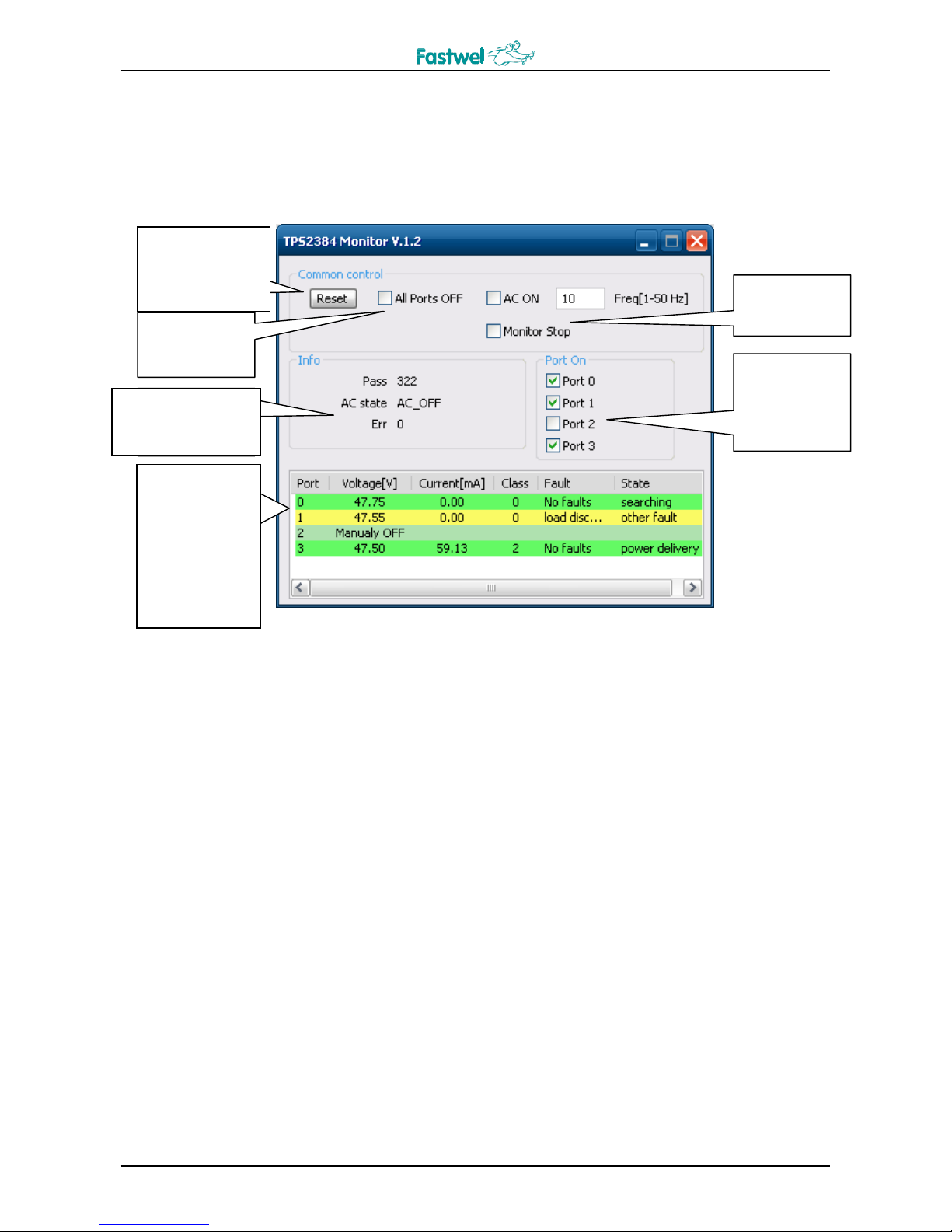
C. Control in Windows XP (Embedded).
For this OS, TPS2384monitor.exe utility is supplied.
Reset and start of
the polling
cycle
Control of
AC mode
Disabling
PoE from all
the ports
Information on
packages SMBus
PoE
Enabling and
disabling
PoE per
each of the
ports
PoE
parameters
on ports:
voltage,
current,
class of
device,
errors and
state
Fig. 2-5: Description of the dialog box of operation with PoE
In order to ensure stable operation of AC mode, it is required to activate "Monitor Stop",
which disables monitoring of data on the operation of PoE itself.
Reset and start
of the polling
cycle
PoE
parameters on
ports: voltage,
current, class
of device,
errors and
state
Information on
packages SMBus
Page 19

NM350 USER MANUAL
© 2 0 1 6
19
N M 3 5 0
Installatio
3 Installation
3.1 Safety requirements
When handling NM350, strictly follow the below safety requirements. Manufacturer shall not
be liable for any damages, arising out as a result of non-observance of such requirements.
Warning!
Turn off the system power supply before installation / removal of the
module. Violation of this rule can pose a threat for your health and
life, as well as could lead to system or module damages.
Warning!
Tightness of the device (IP65) is guaranteed only when
recommended mating parts and plugs are used on unconnected
connectors (para. 1.3).
3.2 Installation methods
NM350 allows two mounting types:
- Mounting to panel with the use of the mounting bracket from among the delivery checklist
(installation kit IMES.465921.001)
- Mounting to DIN-rail using the kit IMES.465921.002.
NM350 can be mounted on the panel, suing a special bracket, included into the kit of
mounting parts together with four screws, and supplied with the switch. In the same way, the
device is mounted onto DIN-rail, using the IMES.465921.002 kit of mounting parts.
Page 20

NM350 USER MANUAL
© 2 0 1 6
20
N M 3 5 0
Additional information
4 Additional information
4.1 Power consumption of NM350
The device uses power supply voltage in the range from +9 V to +36 V from PWR connector.
Consideration should be given to certain requirements, which are essential for ensuring
stability and reliability. In Table 4-1 and Table 4-2 contain values of the maximum allowable
voltages and currents, which if exceeded, could lead to module damages. Power supply sources,
which are to be used with NM350, should be checked in order to meet these requirements.
Table 4-1: Power supply voltage range of NM350
Rate power
supply voltage
Maximum allowable value
+24 V
from +9 V to +36 V
Starting consumption current of NM350, no more than 5 A. Operating consumption current
does not exceed the values, given in the table below:
Table 4-2: NM350 consumption current
Device type
Consumption current, not
including power supply of
external circuits,
A, no more than
Consumption current,
including power supply of
external circuits,
A, no more than
+9V
+9V
NM350 1 9
4.2 Compliance with safety requirements
NM350 corresponds to the general safety requirements imposed on IT equipment according
to the GOST R IEC 60950-2002.
4.3 Noise resistance of NM350
NM350 corresponds to resistance requirements to IT equipment against electromagnetic
interference according to the GOST R 51318.24-99 standard (CISPR 24-97).
NM350 corresponds to the requirements for the level of industrial RF interferences coming
from It equipment in accordance with the GOST R 51318.22-99 (CISPR 22-97).
4.4 Operation conditions
The device retains operability under the following climatic and mechanical effects:
Page 21

NM350 USER MANUAL
© 2 0 1 6
21
N M 3 5 0
Additional information
Table 4-3: Parameters of climatic and mechanical effects
Type of effect
Parameter name
Parameter
value
Document
Temperature change
(at relative humidity up to 80 %,
without moisture condensation)
Low temperature
- 40С
GOST 28209-89 (IEC 682-14-84)
High temperature
+ 70С
1)
Sinusoidal vibration
Range of frequencies
(Hz)
10...500
GOST 28203-89 (IEC 682-6-82)
Acceleration, g
5
Single shocks
Peak acceleration, g
100
GOST 28213-89 (IEC 682-27-87)
Multiple shocks
Peak acceleration, g
50
GOST 28215-89 (IEC 682-29-87)
Number of shocks
1000
4.5 Malfunctions and troubleshooting methods
Table 4-4: Typical malfunctions and troubleshooting methods
Malfunction
Troubleshooting options
Module failed to start and "PWR"
LED is off.
1.
Check the power supply cable: polarity and
integrity.
2.
Check the power supply voltage level.
Connected PoE device failed to start.
1.
Make sure that the device is connected to NM350
port that supports PoE power supply: 1 – 4.
2.
Check the cable connection accuracy: pin-out
and integrity.
No Ethernet connection.
1.
Check the cable connection accuracy: pin-out
and integrity.
2.
Make sure that the port of the device connected to
ports 5 or 6 of NM350, operates in the 1000BaseT
mode.
In case your problem is not described in this table or the suggested options failed to solve the
problem, please contact the device supplier for professional advice.
1)
NM350 module at the ambient temperature of +70С allows connection of PoE devices with a total power
of no more than 30 W. Maximum permissible total power to all the ports under various temperature operating
conditions can be obtained from the diagram (see Fig. 2-4: Dependence of the maximum total load to all
ports on the ambient temperature conditions)
Page 22

NM350 USER MANUAL
© 2 0 1 6
22
N M 3 5 0
Transportation, unpacking and storage
5 Transportation, unpacking and
storage
5.1 Transportation
The module should be transported in a separate packaging box (transport packaging) of the
manufacturing facility, which consists of an individual antistatic bag and a cardboard box, in the
closed transport (automobile, railway, air transportation in heated and pressurized compartments)
in storage conditions 5 defined in the GOST standard 15150-69 (IEC 721-2-1 standard) or in
storage conditions 3 during sea transportation.
The packaged modules should be transported in accordance with the shipping rules,
operating with this particular type of transport.
During handling and transportation operations, the packaged modules should not undergo
sharp pounding, falls, shocks and exposure to atmospheric precipitation. The packaged modules
should be stored in a carrier vehicle in such a manner which will prevent their moving.
5.2 Unpacking
Prior to unpacking, before transportation at subzero temperature of ambient air the modules
should be kept within 6 hours under storage conditions 1 defined in the GOST standard 15150-69
(IEC 721-2-1 standard).
It is prohibited to place the packaged module close to the heat source, prior to unpacking.
While unpacking, it is required to comply with all safety precautions, which ensure its safety,
as well as marketable condition of consumer packaging of the manufacturing company.
At the time of unpacking it is required to check the module that it has no external mechanical
damages after transportation.
5.3 Storage
Module storage conditions for group 1 are defined in the GOST standard 15150-69 (IEC 721-2-
1 standard).
Page 23

NM350 USER MANUAL
© 2 0 1 6
23
N M 3 5 0
Transportation, unpacking and storage
ANNEX B DISCLAIMER
This Disclaimer contains special operating conditions of Fastwel in the following areas: intellectual property, warranty policy,
conditions of the order and delivery.
1 INTELLECTUAL PRORETY
1.1 If any infraction, interference, improper use, illegitimate exploitation and/or violation of the industrial and/or intellectual
property rights of any third party and/or property, exploitation during the use of Fastwel Embedded Module will take place –
Fastwel does not guarantee to replace the materials, computer programs, procedures or equipment affected by the
complaint and under no circumstances doesn't bear responsibility in any form for possible refusal in case of such a
replacement.
1.2 Use of the Fastwel products as well as the objects of intellectual property containing in them, in the ways and for the
purposes, not provided by the present user manual and datasheet isn't allowed without preliminary written approval of
Fastwel.
1.3 Fastwel is not responsible for possible incidents and losses, related to the operation of end devices, in which the original
Fastwel equipment is used.
2 WARRANTY POLICY
2.1 When the detected flaws in an element can be corrected without decreasing the foreseen technical features and
functionality for it, User may demand Fastwel the urgent correction of the failures in additionally agreed period and an
increasing of the period of the guarantee of the element equal as the time elapsed from the formal request to repair the
failures, until the receipt of the repaired element. All costs associated to the correction of failures, included those of
assembly, dismantle, transport, tests, etc, if they exist, shall be prosecuted according the Warranty Policy of Fastwel.
3 ORDER AND DELIVERY CONDITIONS
3.1 The general rule is that all Fastwel equipment prices are determined with due consideration of delivery under the EXW
terms and conditions (Incoterms 2010). Delivery of the products under other terms and conditions should be preliminary
agreed and stated in writing between the parties.
3.2 Unless otherwise expressly agreed with Fastwel, all the deliveries of Fastwel equipment will be carried out only after the
official purchase order is obtained and provided that the ordered products have been prepaid in full. Other terms and
conditions of cooperation should be made in writing.
3.3 Any delivery of Fastwel electronics is submitted with the right package in accordance with the current rules and
standards in the Member States of the European Economic Area. The purchaser independently bears all risks regarding the
compliance of package and marking of Fastwel products with legislation requirements being in effect at the place of
purchased products destination (in the buyer’s country). The specified condition excludes unequivocally any liability of
Fastwel for possible non-compliance of package and marking of products with the requirements of legislation of the country
of products destination.
3.4 In general, all components of the supply are properly protected with respect to freight, in order to avoid any damage to
the supply, third parties, environmental damages or unrelated goods, as consequence of wrong packaging.
3.5 Each package unit is labeled on the exterior area with the indications of product’s Part Number and Serial Number.
3.6 The support documents for the order should be made either in English or in Russian unless otherwise agreed between
parties in writing.
3.7 Fastwel does not pay penalties and does not cover costs associated with delay in the delivery of the products caused by
actions of the third parties, force-majeure etc. - Fastwel doesn't bear any responsibility for non-execution or inadequate
execution of the obligations in a case when it is caused by actions of the third parties (for example producers or suppliers of
accessories), force majeure etc.
3.8 Fastwel declares that independently and at any time without damage, it has an exclusive right to define and change
functionality architecture, bill of materials of its products without any preliminary coordination and approvals of the third
parties.
4 OTHER CONDITIONS
4.1 Fastwel has the obligation to respect the current Russian legislation (including, but not limited to environmental, labor,
social laws) in each moment and to apply it to its embedded electronics considering all and each execution phase, that is to
say, from the design until the commissioning and subsequent maintenance. In this regard Fastwel is not liable to the user or
other persons in connection with possible changes of the company’s rules (including, but not limited to warranty, ordering
policy) caused by changes of the Russian legislation.
4.2 Unless otherwise expressly agreed in writing, Fastwel provides no training for assembly\installation\adjustment\operation
of its equipment.
 Loading...