

Page 1
1
INDOOR TANNING EQUIPMENT
CARE, USE AND INSTALLATION
INSTRUCTIONS
Model:
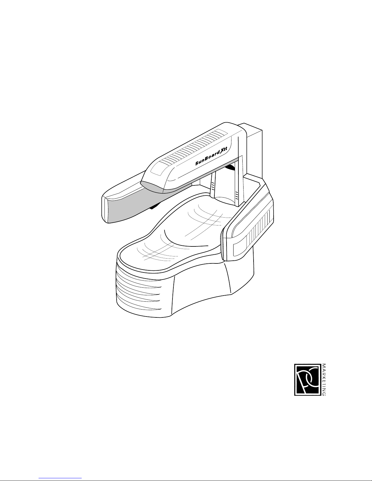
SunBoard XTT
PC MARKETING
1040 WIL T A VENUE
RIDGEFIELD, NJ 07657
1-800-FAST TAN
Page 2

2
Preface
Your unit has been built in accordance with the latest state of technology and is safe.
However, the unit can be dangerous if it is operated by persons who have not received the necessary training or instruction, or if it is used improperly. Therefore, everyone
entrusted with the task of installing the unit, setting it into operation, operating, maintaining and repairing it must read and understand the Operating Instructions and especially - the Safety Instructions. Before the unit is used for the first time, you and/or
your personnel should definitely receive instructions from the specialist consultant. If,
contrary to expectations, technical defects occur in your tanning unit, please contact
the customer service department or your dealer.
LIST OF CONTENTS PAGE
1 NOTES ON SAFETY .................................................................................... 3-4
1.1 Before Initial Operation ............................................................................... 3
1.2 Using the Unit for the First Time ................................................................... 3
1.3 Safety Warning........................................................................................... 3-4
1.4 Operation...................................................................................................... 4
1.5 Product Liability ............................................................................................ 4
1.6 Emergency Procedure ................................................................................. 4
1.7 Explanation of Danger Symbols ................................................................. 4
2 OPERATION I INFORMATION FOR THE USER OF THE UNIT........................5-6
2.1 Starting to sunbathe .................................................................................... 5
2.2 Important Technical Details........................................................................ 5
2.3 Interior Tanning-Space ................................................................................. 5
2.4 Cleaning the Acrylic Sheet: Use uwe Cleanser Only! ............................... 6
TECHNICIAN SPECIFICATIONS FOR UWE-PROFESSIONAL USERS
3 INSTALLING THE PROFESSIONAL UNIT .................................................... 6-11
3.1 Installation Site and Delivery Condition .................................................... 6
3.2 Installation and Assembly....................................................................... 6-10
3.3 Connecting the Unit’s Air Outlet (Figure 1 and 2) .................................. 11
3.4 Electrical Connection ................................................................................ 11
3.5 Coin Operation or Central Control (Figure 2) ........................................ 11
4 SETTING INTO OPERATION .................................................................... 12-13
4.1 Technical data, dimensions and UV type .......................................... 12-13
4.2 Before Setting into Operation................................................................... 13
4.3 Setting the Unit into Operation for the First Time ................................... 13
5 CLEANING - IMPORTANT INFORMATION FOR THE OPERATOR ................ 13
6 MAINTENANCE AND REPAIR................................................................ 14-17
6.1 Changing the Acrylic Sheet ...................................................................... 14
6.2 Exchanging the high pressure burner.................................................. 15-17
6.3 Exchanging the illumination light ............................................................ 17
6.4 Changing the Filters ................................................................................... 17
7 ADVICES ..................................................................................................... 17
8 TIPS FOR CORRECTING MINOR DEFECTS................................................... 1 8
9 WASTE ......................................................................................................... 19
1 0 CUSTOMER SERVICE ADRESS ..................................................................... 19
Page 3
3
1 SAFETY INSTRUCTIONS:
1.1 Before installation and placing in operation, the Safety Instructions and Operating Instructions must be carefully read and observed.
1.2 Before the unit is placed in operation, the local Safety Regulations and the Safety Instructions
must be complied with.
1.3 SAFETY / WARNING
DANGER – ULTRAVIOLET RADIATION
Follow instructions. Avoid overexposure. As with natural sunlight, overexposure can cause eye
and skin injury and allergic reactions. Repeated exposure may cause premature aging of the
skin and skin cancer. Consult physician before using sunlamp if you are using medication or
have a history of skin problems or believe yourself especially sensitive to sunlight. If you do not
tan in the sun, you are likely to tan from the use of this product.
WEAR PROTECTIVE EYEWEAR: FAILURE TO MAY RESULT IN SEVERE BURNS OR LONG – TERM INJURY
TO THE EYES.
Therefore, you must observe the following Safety Instructions:
The ultraviolet and visible radiation is very intense. DO NOT stare at the tanning lamps.
While tanning, close your eyes, and always use the protective eyewear that is supplied.
Before tanning, always remove jewelry.
DO NOT tan more frequent than once every two days.
For recommendations about exposure times and recommended frequencies, please see below
RECOMMENDED EXPOSURE SCHEDULE, which is affixed to every unit.
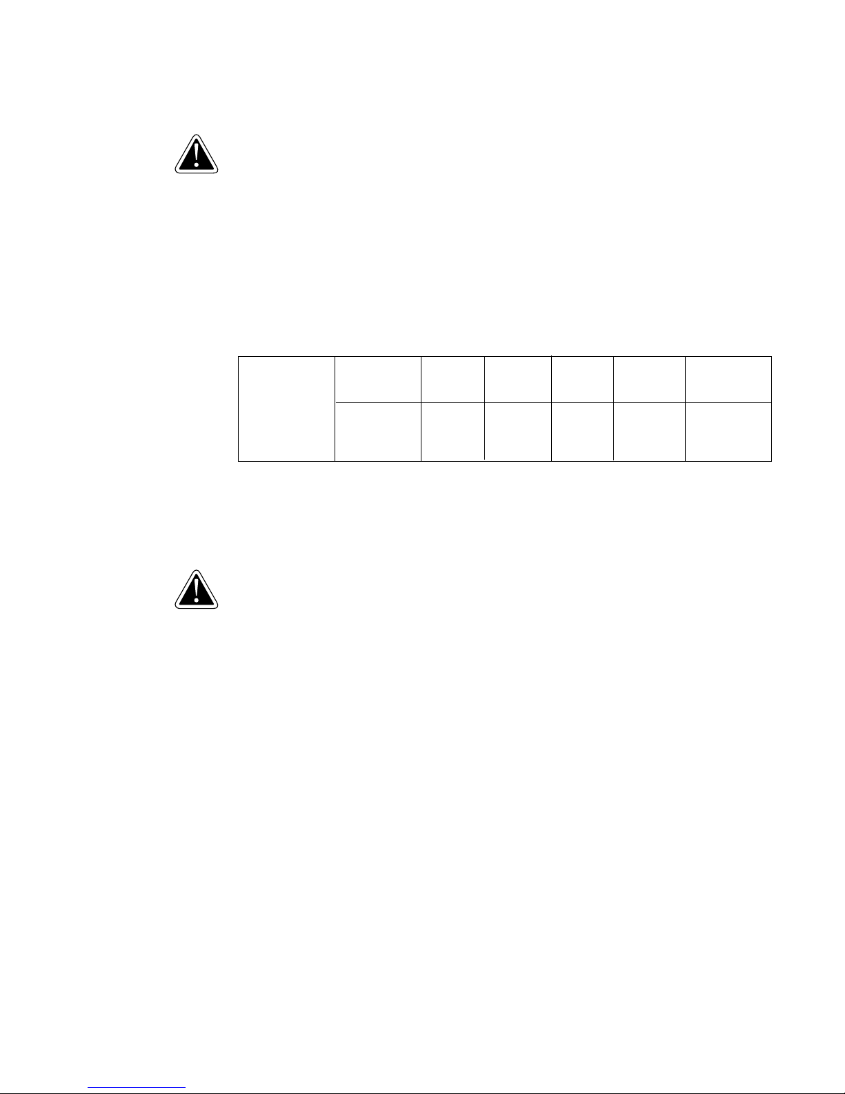
RECOMMENDED Skin Type WEEK 1 WEEK 2 WEEK 3 WEEK 4 WEEKLY
EXPOSURE 1st – 3
rd
4th – 6
th
7th – 8
th
11th – 15
th
Subsequent
SCHEDULE Session Session Session Session Session
II – Fair 3 min. 5 min. 9 min. 15 min. 15 min.
III – Average 5 min. 6 min. 9 min. 15 min. 15 min.
IV – Brown 5 min. 8 min. 11 min. 15 min. 15 min.
V – Dark Brown 5 min. 8 min. 11 min. 15 min. 15 min.
Tanning can begin on a regular basis (allowing 48 hours between sessions). An appearan-ce
of tanning normally occurs after a few exposures and maximizes after four (4) weeks of
exposure following the recommended exposure schedule of two (2) weekly 12 minute sessions
is recommended from the fifth week onward.
USE PROTECTIVE EYEWEAR WHENEVER THE EQUIPMENT IS ENERGIZED. READ THE INSTRUCTION
BOOKLET BEFORE USING THIS PRODUCT.
WARNING
If you have been diagnosed by a physician as being allergic to the sun or are currently taking
photosensitive medications, consult your physician before using this product.
Children, persons with fair skin, elderly persons and persons who have a history of skin problems
or believe yourself especially sensitive to sunlight, should avoid using this product. If you do not
tan in the sun, you are likely to tan from this product.
Certain drugs – particularly those designed to enhance photosensitivity – maybe cause individuals
under their influence to experience adverse effects and those people ought to avoid exposure
to UV sources of all kinds. Doctors will advise persons taking these drugs of possible adverse
effects.
It is recommended that only one person at a time use the tanning system. Use protective eyewear
while tanning. One pair of protective eyewear is provided with each unit sold.
Occasionally, persons, using the tanning system will experience a slight reddening of the skin –
usually in small patches – after the second or third session. This redness is often accompanied by
an itching sensation. This is nothing more than a heat ”rash” caused by heat from the lamps
within the system. It is generally very limited. It will go away within approximately 24 hours and
should not reappear. This rash can be lessened or prevented by applying moisturising lotion to
the affected area after the tanning session is complete.
CAUTION:
WHILE THERE IS NO IMMEDIATE CLINICAL EVIDENCE REGARDING UV EXPOSURE
AND IT S EFFECTS UPON EXPECTANT MOTHERS, IT IS STRONGLY ADVISED THAT
EXPECTANT MOTHERS BE DISCOURAGED FROM USING THIS PRODUCT.
EXPOSURE TIMES AND FREQUENCIES
Melanin, the brownish pigment produced by special cells in the base layers of the skin determines
the individual ability to tan. As the skin is exposed to ultraviolet rays, the melanin is activated and
combines with protein cells that rise to the skin’s surface, thus producing a tan. The amount of
melanin in your body determining how quickly and darkly you can tan.
Warnin
g
Warnin
g
Page 4
4
NOTE
THE TAN PRODUCED BY THIS UNIT IS A DEEP. RICH ”COSMEDIC” TAN, HOWEVER, REGARDLESS OF
HOW MUCH AN INDIVIDUAL MAY TAN WITH THIS UNIT, IT WILL NOT PROVIDE ADEQUATE PROTEC-
TION AGAINST OVEREXPOSURE TO NATURAL SUNLIGHT OR UVB TANNING SYSTEMS.
SKIN TYPE II - THIS IS THE INDIVIDUAL THAT USUALLY BURNS EASILY AND SEVERELY.
TANS MINIMALLY OR LIGHTLY AND PEELS.
SKIN TYPE III - OFTEN REFERRED TO AS ”AVERAGE” COMPLEXION.
BURNS MODERATELY AND TANS ABOUT AVERAGE.
SKIN TYPE IV – THIS INDIVIDUAL BURNS MINIMALLY, TANS EASILY AND ABOVE
AVERAGE WITH EACH EXPOSURE.
SKIN TYPE V - THIS INDIVIDUAL RARELY BURNS, TANS EASILY
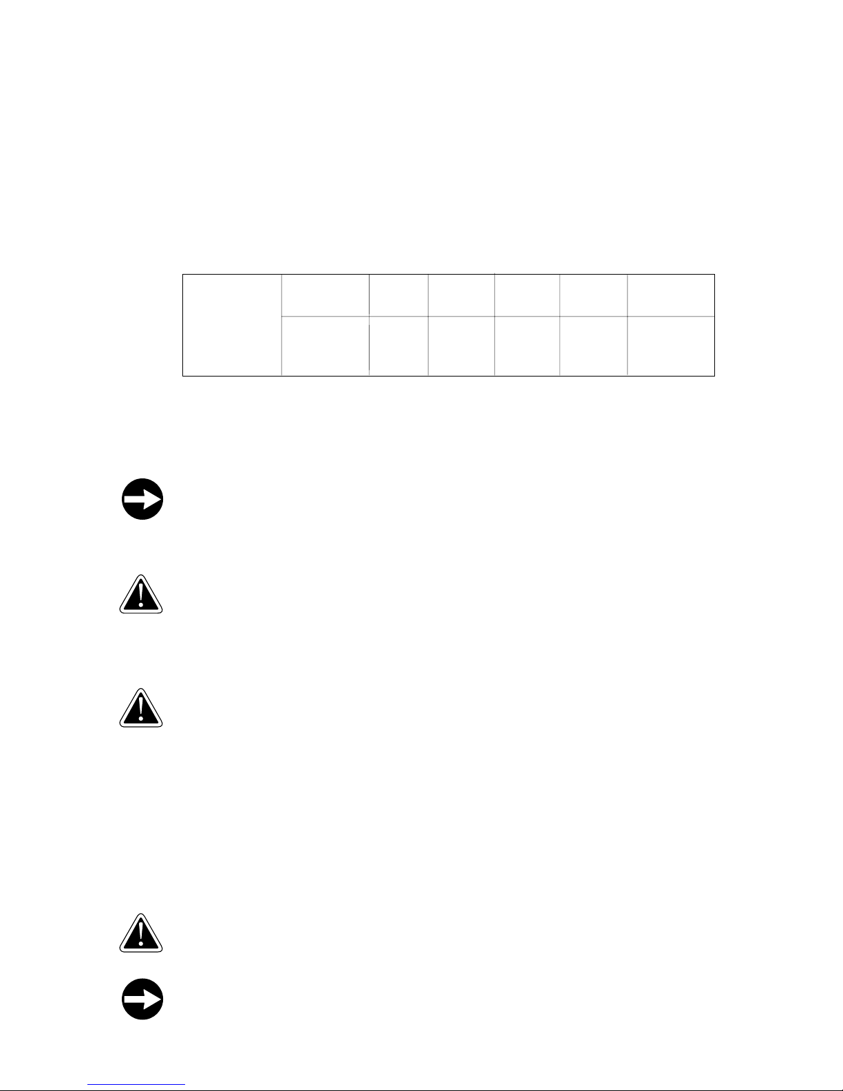
RECOMMENDED EXPOSURE SCHEDULE
RECOMMENDED Skin Type WEEK 1 WEEK 2 WEEK 3 WEEK 4 WEEKLY
EXPOSURE 1st – 3
rd
4th – 6
th
7th – 8
th
11th – 15
th
Subsequent
SCHEDULE Session Session Session Session Session
II – Fair 3 min. 5 min. 9 min. 15 min. 15 min.
III – Average 5 min. 6 min. 9 min. 15 min. 15 min.
IV – Brown 5 min. 8 min. 11 min. 15 min. 15 min.
V – Dark Brown 5 min. 8 min. 11 min. 15 min. 15 min.
No two individual skin tones are the same. A tan to one person may be different to another,
and session length may vary. It is recommended that, following a tanning session, a skin
moisturiser be applied. This promotes a smoother more even looking tan. Equally important –
many facial make –ups have oil bases and should be removed prior to each tanning session.
NOTE
SINCE THE BACK AND STOMACH AREAS OF THE BODY WILL RECEIVE THE MAJORITY OF THE
TANNING RAYS, IT IS RECOMMENDED THAT INDIVIDUALS SPEND ONE HALF OF EACH SESSION
LYING ON EACH SIDE OF THE BODY TO ACHIEVE A FULL-BODIED TAN.
WARNING
COMMERCIALLY AVAILABLE CREAMS, LOTIONS AND OILS CONTAIN SUNSCREENS WHICH FORM A
PHYSICAL BARRIER ON THE SKIN THAT PREVENTS THE UV RAYS FROM PENETRATING AND INDUCING
A TAN. IT IS RECOMMENDED THAT YOU ONLY USE CREAMS, OILS OR LOTIONS THAT DO NOT CONTAIN
POLYTHENE/GLYCOL MONOLAURATE AND ARE DESIGNED FOR USE WITH INDOOR TANNING
EQUIPMENT. FAILURE TO COMPLY WITH RECOMMENDATIONS AND WARNINGS STATED ABOVE
MAY VOID THE MANUFACTURER’S WARRANTY.
WARNING!
THIS UNIT MUST NOT BE USED IF THE TIMER IS FAULTY OR IF THE FILTER GLASS PLATE IS BROKEN.
1.4 Proper Operation
All units are intended solely for tanning in the interior of buildings. Operate the unit only in places
where there is no risk of hazards and only in dry rooms. The rooms must be wellventilated (adequate
air inflow and air outflow). If the unit is operated in a tanning salon, extremely strict hygiene must
be ensured both on the unit and in the room. Any type of use not complying with these remarks
is improper, and the manufacturer will not accept liability for any resulting damage or injury.
Proper operation also includes compliance with the operating, maintenance and repair conditions specified by the manufacturer. Qualified service technicians authorized by PC Marketing,
Inc should only perform maintenance work, and repair work. If unauthorized modifications are
made on the units, the manufacturer will not accept liability for any resulting damage or injury.
1.5 Product Liability
The unit may only be operated in the proper manner. If it is operated in an improper manner,
the user assumes sole responsibility. In such cases, the manufacturer cannot accept any liability.
1.6 Emergency Procedure
Switch off the electrical supply to the unit by operating the main power switch or circuit breakers, and source the unit to prevent it from being switched on again without authorization.
1.7 Explanation of Danger Symbols
Warning!
In these Operating Instructions, we have used the word warning to mark all concerns that relate
to operating safety. Please post safety instructions for all users.
In these Operating Instructions, we have used the word note to mark all concerns, which contain
essential information for operating the unit. Please be sure they are followed in order to avoid
damage to the unit.
Function
Warnin
g
Function
Warnin
g
Warnin
g
Page 5
5
Warnin
g
Warnin
g
1
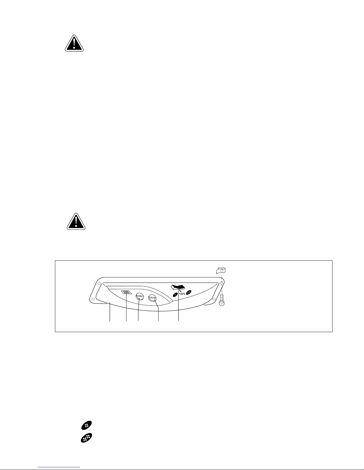
48 88 90 89 91
OPERATION I INFORMATION FOR THE USER OF THE UNIT
2.1 Start of Sunbathing
Observe the time chart. Do not exceed the sunbathing time recommended for your skin type. You
must definitely avoid sunburn. Never sunbathe if you already have sunburn. Depending on the type
of skin there is a certain final bronzing to be achieved. This bronzing can not be rein force furthermore by using a solarium, but only maintained. When sunbathing, use the protective goggles. Person
whohave had operations on their eye lenses must wear protective goggles. The sunbathing period
can at any time be interrupted with the red EMERGENCY-OFF (NOT-AUS) button of the slot machine
and with the red STOP-button (89) of the unit.
Insert coins or tokens. The initial delay period starts. The unit switches itself on automatically.
2.2 Important Technical Details
Important information! You must read this!
• Climate desired (91, seesaw-button on the operating panel)
Here you determine how much cooling air will be blown on the body.
• Ventilator
The ventilator in the tripod still goes on 4 minutes after switching off the unit, in order to cool down the unit.
• Lighting effect
Behind the small covering hood (57) standing beside the feet, there is a permanent shining source of light.
• BreakSafe
The XTT filter discs of the lounger and the XTT filter discs of the tanning arms are equipped with a BreakSafe
protection. That is to say, whenever a filter disc breaks or whenever you forgot to put in a filter disc when
exchanging the burner, the electrical circuit will be interrupted and the unit can not be started
(see Section
8 BreakSafe).
• Speakers (34, picture 3)
There are two speakers so that you can enjoy the music played on the central sound system while you tan
(See picture 2 number 12).
2.3 Inside area of the tanning unit
Lie down on the lounger.
While sunbathing, keep your arms near your body on the lounger.
If the lights are still off, the initial delay period is active. The lights automatically switch on after the end of the initial
delay period. The interval of tanning is determined by the construction of the unit. Now you can reach the operating
panel (48, picture 1) comfortably with the right hand.
• START/STOP-button, LED-display (picture 1)
As soon as the lights switched on, the 2-figured LED-display (88) is counting up the time in minutes. Here you can
read the sunbathing time that you have spent. After the end of the sunbathing time the unit switches off and the
display shows 0. While sunbathing, you can interrupt the sunbath with the red STOP-button (89) and with the green
START-button (90, starts again after approx. 4 minutes) you can start again. The sunbathing time keeps going on
during this interruption, that is to say, the display goes on counting.
• Seesaw button ventilator (91)
With the seesaw-button (91) you choose the desired climate for sunbathing. The cooling air will be carried over
the body out of the jet (92, picture 3) and out of the ventilation slots (92). On the positioning of the seesaw
button depends the power of the supply of cooling air.
Middle position Supply of cooling air OFF
Symbol Supply of cooling air medium power
Symbol Supply of cooling air full power
Page 6

6
Warnin
g
Warnin
g
Function
Function
2.4 Cleaning the Acrylic Sheet: Use uwe Cleanser Only!
Always ensure extremely strict hygiene.
After every period of use, the lying surface must be disinfected and cleaned.
uwe cleanser and other cleaning materials must not be sprayed into the eyes. Do not spray them
into naked flames.
Do not drink them.
Keep out of the reach of children.
Use cleaners in accordance with the instructions and observe the manufacturer’s soaking times.
Do not pour or spill liquid over the unit, so that no moisture will penetrate under the covers and
into the electrical equipment.
After every tanning session, clean the acrylic sheets with the uwe cleanser „PICCOBELLO“, or with the „Paletti
Hydrovlies“ tissues. When using the uwe cleanser „PICCOBELLO”, spray it onto the acrylic sheet and let it react for
at least 60 seconds. Always dry it off with a clean cloth.
TECHNICIAN SPECIFICATIONS FOR uwe-PROFESSIONAL USERS
3 INSTALLING THE PROFESSIONAL UNIT
The unit must be installed only by personnel of the uwe company or by authorised persons. To install
the unit, at least two persons are needed. The rooms in which the units are to be installed must be
well ventilated (adequate air inflow and outflow); otherwise there is a risk of overheating!
All plug-in connections are encoded.
3.1 Place of installation and condition of delivery
• The whole unit is being transported and delivered on a pallet. Various individual parts of the unit are packed
in cardboards and tied up safely with assembly belts onto the pallet. The pallet with the unit will be unloaded
by a hydraulic ramp or fork-lift truck at the place of destination. In order to install the unit on the planned place
of installation, it will have to be partly dismantled on the pallet and be re-assembled again on the planned
place of installation. All units are exclusively destined for sunbathing in the inside area of buildings. The unit is
only al lowed to be operated in areas where there is no danger of explosion and in dry rooms. The rooms have
to be well ventilated (adequate air inflow and outflow).
3.2 Installation and assembly
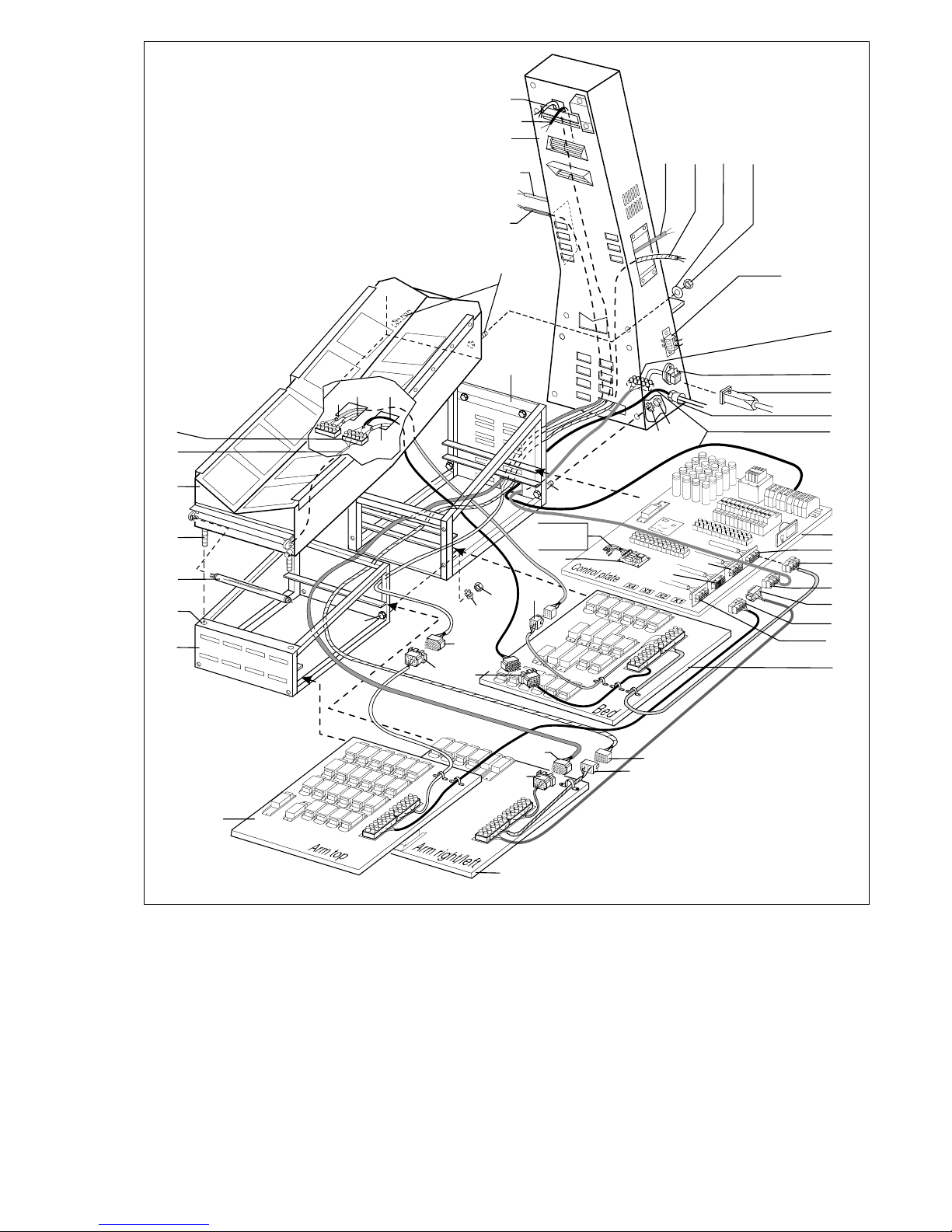
• Disassemble parts of the unit on the pallet
Untie the assembly lines and carry the individual parts (tanning arms, covering hood, tripod) packed in cardboards to the planned place of installation. Now there still remain the lounger and the footrack assembled on
the pallet. The Plexiglas plate lounger (1, picture 4) lies free on top of the pipeframe (2). Lift down the Plexiglas
plate together with someone. If the pipeframe is fastened together with the tripod, unwind the screws and
then take down the pipeframe (2) as well. Untie both covering plates (3 and 4, picture 3) from the parts of the
footrack. Check up, if all plug-in connections are removed and then pull the assembly plates out of the guide
bar. Then lift the light case (6, picture 2), it is only hung up onto the footrack with two shankscrews (13). Further
on, remove the hexagonal nuts M 8 (7) and toothed disks (8) between both footrack parts. Now you can carry
both footrack parts separately to the place of installation.
• Assemble the footrack (picture 2)
Place the unit according to the sizes of your place of installation. The unit is shaped preferably for a diagonal
corner installation. Organize both parts (9 and 10) of the footrack according to picture 2. Connect these by
introducing the four M 8 screws (11) welded into the front footrack into the reliefs of the back part of the
footrack and by securing the screws with one toothed disk A 8,4 (8) and one hexagonal nut M 8 (7) each. Then
put the lightcase onto the footrack, so that the shankscrews (13) emerge into the drill-holes (14) of the
footrack designed for this purpose and the connecting cables (15 and 16) emerge into the back part of the
footrack. Check up, if the cable (5) of the illumination light is jammed onto the unit’s terminal (17). Push the
assembly plate lounger (19) right backwards into the middle guide bar, the assembly plate control unit (20)
into the upper guide bar of the back part of the footrack (19) as far as it will go. Then arm the front part of the
footrack by pushing the assembly plate upper arm (21) into the upper guide bar -and the assembly plate arm
right/left (22) into the lower guide bar- of the front part of the footrack (9) as far as it will go.
All the plug-in connections of the unit are encoded.
Take the 9-poled cable X8 (24) and the 18-poled cable X9 (23) of the assembly plate lounger and connect
these together with the connecting cables (15 and 16) of the lighting case (6), which have been previously
pulled through. Put the plugs X8a and X9a of the lighting case together with the corresponding socket
connectors X8a and X9a of the BreakSafe Control (105) on the Control Board.
Put the 18-poled cable X4 (25) of the assembly plate lounger together with the corresponding socket connector
X4 (26) of the assembly plate control unit.
The plug-in connections are numbered. Place the same numbers together.
Page 7
7
2
53 32 33
37
42
27
50
31
15
16
11
10
7
8
17
5
6
13
78
14
9
23
42
47
63
62
95
39
30
29
20
28
22
21
54
53
51
50
19
36
38
24
52
49
25
26
18
106
105
X5a-X9a
12
connection
Speaker
X5a
X6a
X7a
X8a
X9a
see picture 8
• Assembly of the tripod (27, picture 2)
Remove the tripod (27) out of the cardboard and disassemble the back covering hood (55, picture 4). Arrange the tripod in the middle behind the footrack. Thereby introduce the pins of the M8 screws, which are
welded in and standing out of the foot casing (4 pieces) and the light casing (2 pieces), into the corresponding
drill-holes of the tripod. Secure the screws (28) of the foot-casing with toothed disks A8, 4 (29) and octagonal
nuts M8 (30), secure the screws (31) of the light-casing with washers (32) having 25 mm in external diameter
and with hexagonal nuts M8 (33).
Thereafter also put the 18-poled cable with plug X3 (36) that comes out of the unit’s terminal (37) in the tripod,
together with the corresponding socket connector X3 (38) of the assembly plate control unit. Further on, carry
the long cable (39) of the assembly plate control unit to the right through the square opening and carry it
outside through the pusher airscrew (95) with tractive relief. Leave behind enough cable in the back part of
the footrack, so that the assembly plate control unit can still be pulled out. Fix the covering hood
(40, picture 3) on to.
Page 8
8
3
Function
44
40
92
41
43 66
81 80 78 9 3 10 4
83
86 85
66
107
108
107
84
104 84 94
46 45
48
64
34
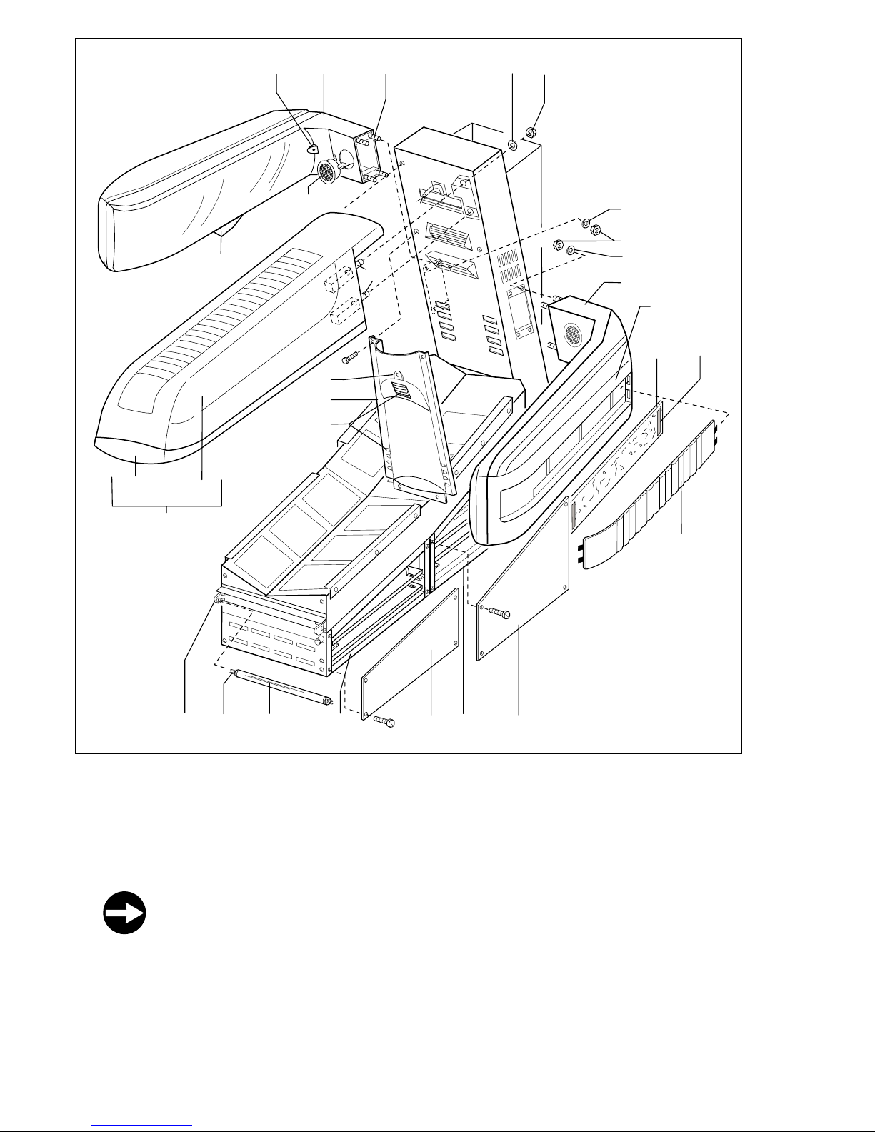
• Assembly of the upper tanning arm (41, picture 3)
Take the upper tanning arm (5 sunbathing units) and hold it in front of the respective place of installation at the
tripod. First pull the cable X5 (42, picture 2) with the 18-poled plug-in connection and the 4-poled cable X5a
(105) through the gap relief (25 x 25 mm) into the tripod. Then introduce the pins (64) of the arm into the gaps
of the tripod. Thereby push the acrylic sheets (43) over the support (44) of the covering hood (40). After this,
secure- coming from the tripod the four pins (64) with disks (46) having an external diameter of 25mm and with
hexagonal nuts (45).
You really must tighten up the nuts (45).
Pull the both cable with plug X5, X5a (42, picture 2) down onto the bottom of the tripod, and through the gap
of the tripod into the footrack.
Put the plug X5 (42) together with the corresponding socket connector X5 (47) of the insertion arm upside.
Put the plug X5a together with the corresponding socket connector X5a of the BreakSafe Control (105) on
the Control Board.
Put the pin casing X1 (18) of the assembly plate arm top (21) together with the respective 18-poled socket
connector X1 (106) of the assembly plate control unit.
Page 9
9
Warnin
g
Function
Function
Function
• Assembly of the tanning arm right/left (84, picture 3)
Attention! Take care that you assemble the tanning arm with the operation panel (48) on the
correct side (left).
At first take the tanning arm with operation panel and hold it in front of the corresponding place of assembly
at the tripod. Pull the 18-poled cable X7 (50, picture 2) and the cable X7a through the gap into the tripod. Then
introduce the pins (94) of the arm into the gaps of the tripod. After that, secure -coming from the tripod-the
four pins (94) with disks (107) and nuts (108).
You really must tighten up the nuts (108).
Pull the 18-poled cable X7 with the plug (50, picture 2) and the cable X7a down onto the bottom of the tripod,
through the gap of the tripod into the footrack. Pull the cable X7 with plug (50) through up to the assembly
plate arm right/left (22) and there put the plug together with the corresponding socket connector X7 (51). Put
the plug X7a together with the corresponding socket connector X7a of the BreakSafe Control (105) on the
Control Board.
Assemble the second tanning arm onto the right side of the tripod. This tanning arm has an 18-poled
cable X6 (53) with plug and the BreakSafe cable X6a, these cables you have to pull through down
wards into the footrack. The plug X6 (53) will then be put together with the 18-poled pin-casing X6 (54)
of the assembly plate arm right/left. Put the plug X6a together with the corresponding socket connec
tor X6a of the BreakSafe Control (105) on the Control Board.
Put the pin casing X2 (52) of the assembly plate arm right/left (22) together with the respective 29-poled
socket connector X2 (49) of the assembly plate control unit.
All plug connections can be found in these Tables
Control board Board lounger Board Arm top Board Arm right/left
Base X9, 18-pin
X8, 9-pin
Control board X4, 18-pin X1, 18-pin X2, 29-pin
Tanning Arm Top X5, 18-pin
Tanning Arm Right X6, 18-pin
Tanning Arm Left X7, 18-pin
Tripod X3, 18-pin
BreakSafe connections
Arm Top Arm Right Arm Left Base
Break Safe Control (105) X5a X6a X7a X8a/X9a
on the Control board
Check up, if all the assembly plates have been pulled backwards and if all plug-in connections have been put
together.
Then assemble both covering hoods (3 and 4) onto the respective part of the footrack (9 and 10). Beginning from
behind, fix the big covering hood (55) with the screws 4,2 x 9,5 onto the tripod.
Page 10
10
4
Warnin
g
Warnin
g
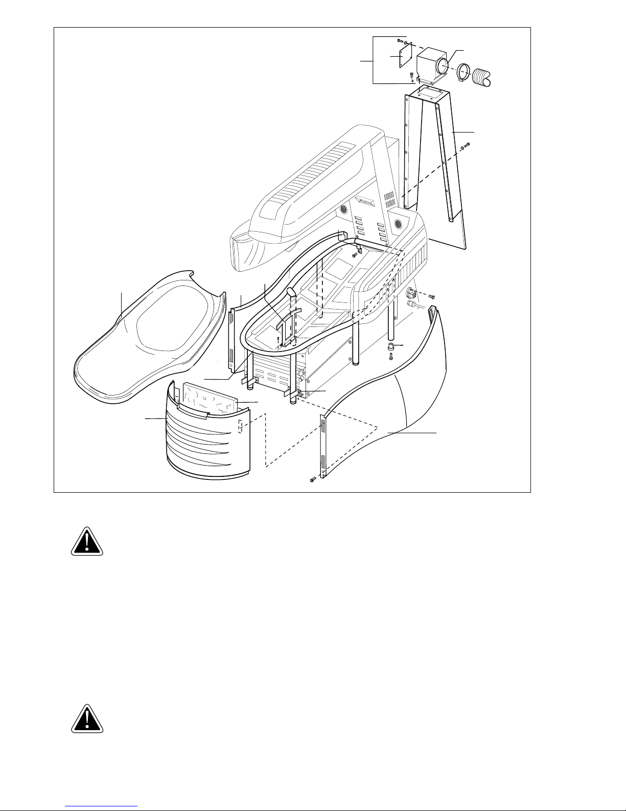
• Assembly of the lounger (picture 4).
Place the pipeframe (2) over the footrack. Take care, that the front foot is being fixed by the support (73).
Attention! The feet of the pipeframe are adjustable for height. The knurling screws (103) have been
unscrewed up to 25mm ex works. Please check! If not, unscrew the knurling screws up to 25 mm. You
must adjust the pipeframe to the conditions of your ground.
1. Place the pipeframe over the footrack.
The footrack must stand up straight.
2. Level out the unevenness of your ground with the knurling screws. To achieve this, rather unscrew than tighten
up the knurling screws.
Fix the pipeframe by tightening up the screws (M8 x 20) through the long holes of the edges (93) into the nuts
welded into the tripod. Then arrange the three covering hoods (56, 57, 58) around the pipeframe. The two
covering hoods (56 and 58) arranged on the sides of the pipeframe will be fixed onto the tripod by a strip
fastener and screwed together at the front side with their fastening tabs (4,2 x 9,5). On these fastening tabs the
small covering hood (57) will then be fixed, again by strip fasteners, starting from the front. Check, if the
verticalplate (101) is assembled. Then, together with someone else, take up the acrylic sheet (1) and place it
on to the pipeframe. The acrylic sheet will be supported by the vertical plate (101).
Attention!
The border circulating the acrylic sheet slips over the edges of the 3 covering hoods.
The acrylic sheet shall not rest on top of the covering hoods! The space between acrylic
sheet and the covering hoods should be approx. 5 mm.
If this space is not ensured, readjust the knurling screws.
61
60
59
55
1
93
58
101
103
2
82
57
73
56
Page 11

11
Warnin
g
Warnin
g
Warnin
g
Warnin
g
3.3 Connecting the Unit’s Air Outlet
Attention! Important Information!
On using the SunBoard XTT unit you really must draw oft the already warmed up cooling air through
a direct air removal.
uwe recommends as standard connexion a special adapter part (59), which you can obtain from
uwe.
Accessorial adapter part (59, picture 4)
Fix the adapter part with 4 screws 4,2 x 9,5. Choose the side, into which direction (to the sides or upwards) you want
to draw off the air. There you have to unscrew the closed covering plate (60) and fix at that place the covering
plate (61) with the pipe-connecting piece. All the remaining sides of the adapter part must be closed. In case that
the digging through the wall can’t be positioned directly behind the pipe-connecting piece, then the distance
can easily be bridged over with an air tube (diameter 300 mm). Fix the tube for used air on the pipe-connecting
piece with a tube clip. Carry the tube for used air by means of tube connecting pieces, wall case and automatic
exterior top flap into the open air, or connect it onto a ventilation shaft. You can obtain these parts with a
diameter of 300 mm at your specialized store or at uwe.
Attention, important information! You must observe this; otherwise there is a danger of over heating!
To avoid excessive resistance to the air flow, the hose should not be longer than 6 m and should be
laid so that any bends have as large a radius of curvature as possible, and without any kinks. If the
air is discharged to the outside via a ventilation duct, it must be ensured that the flow resistance in
the interior of the duct is as low as possible; if necessary, an additional fan might need to be
installed there. In this case, please consult a ventilation engineer.
The rate of air discharge is about 2200 m
3
/hour; accordingly, fresh air must be allowed to enter the
cubicle at the same rate. Therefore, you must provide fresh air openings in the wall of the cubicle,
having an unobstructed cross-section of at least 1000 cm2.
Further information on effective ventilation can be found in the brochure „AIR-CONDITIONING TIPS“
which is available from your dealer or from us.
3.4 Electrical Connection
Important:
The connection work may only be done by an electrical expert in accordance with the applicable
regulations.
The person installing the unit must carry through an inspection and make a report on it.
Operating Voltage: 3PE~60 Hz 220 V 50 A.
An isolation switch (plug, main switch, fuses, Fl circuit breaker) is to be provided in this line with which the unit can
be completely (all poles) separated from the mains power supply. The circuit diagram belonging to each unit is
attached separately to the respective unit.
Attention!
In case of connection over a Fl circuit breaker it has to be observed, that during the process of ignition there occur
derivating current points, which are so short-termed, that they can only be detected by an oscillograph. If various
units are operated together with one Fl circuit breaker, when switching on the units simultaneously, the points may
add and lead to release the Fl circuit breaker, without there being any defect on the unit.
Therefore never connect more than 1 unit over one Fl circuit breaker £ 30 mA.
3.5 Coin Operation or Central Control (Figure 2)
Coded Plug for Connection to the Coin Switch and Central Controller (Figure 2)
Plug the coded plug (62) with cable into the special plug with circlip (63). This cable forms the connection between the coin box and the central controller. The cable has 4 cores (phase, switched phase, neutral, PE). The coin
box does not therefore need a separate mains power supply connection. The switches in the coin box and in the
central controller must be capable of being loaded to 16 A inductive.
Setting the Coin-Operation Time Switch
The unit may only be connected by a qualified electrician.
Information on operating and setting the unit can be found in the coin meter operating instructions.
For safety reasons, ensure that the maximum tanning session with this unit is limited to 15 minutes.
If you press the red emergency button of the Coin Meter, both the digital display and the high pressure bulbs are
extinguished. The only way to restart the unit is to insert coins again. (Restart of the burner only after approx. 4
minutes).
Page 12
12
5
dimensions in mm
54321
4321
350
2330
1950
645
1920
890
600
475
1010
1635
370
290
660
1950
780
1010
1635
800
290
370
1950
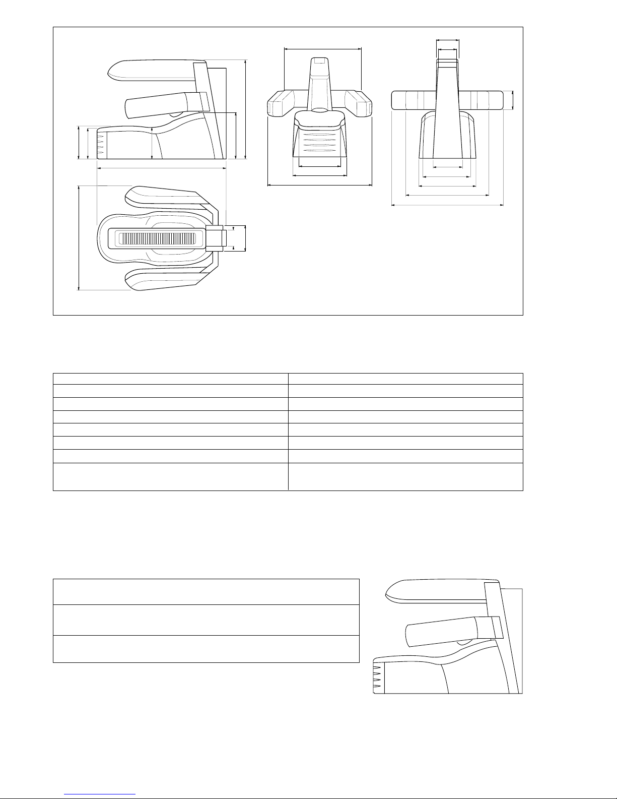
4 SETTING INTO OPERATION
4.1 Technical data and dimensions
Designation SunBoard XTT
Type of unit 7823
Power (W ) 13.500
Operating voltage (V) 3PE~60 Hz 220 V 50 A
Fusing (A) 3 x 50 A (K 50)
Weight (kg) 48 0
Dimensions Length (mm) 2.330
Width (mm) 1.950
Height (mm) 1.920
Noise level <70dB (A).
Room temperature for operation max. 95°F (35°C).
The place of installation has to show a load-bearing capacity of at least 500 kg/m² and has to be even.
*We reserve the right to make technical changes
LAMP CONFIGURATION
If the lamps are not placed in the correct position, this may result in a loss of performance and lifetime. Please
ensure to use the lamps as described below and place them as shown in the picture:
The designation of the lamps is printed on the ceramic socket of the lamp.
Please note: High pressure bulbs loose performance after a certain time that is not remarkable visually. You have
to adapt to this loss in performance by using longer tanning sessions. uwe recommends to exchange the lamps
after 500 hours.
Center arm: 5 x 1 kW lamp BQ 1176 Z4, Art. No. 45006404 (Pos. 1 - 5)
Lateral arms: 4 x 1 kW lamp BQ 1176 Z4, Art. No. 45006404 (Pos. 1 - 4)
Base 10 x 400 W lamp BQ 477 E, Art. No. 8000 7738
Page 13

13
Function
Warnin
g
Cover of the Lights
The sources of UV-radiation in the arms are covered each by one 3-4,5 mm thick filter with the denomination Type
322 XTT (PKZ 02935) and by one disk out of 3 mm thick acrylic glass. The sources of UV-radiation in the lounger are
covered each by one 3-4,5 mm thick filters with the denomination Type 324 XTT (PKZ 02936) and with one disk out of
6 mm thick acrylic glass. Between the lights and the light-casing there is a reflector made out of high-gloss rolled,
electrolytic polished and anodized aluminium.
In case of any modification of the disks, the burners, of other spare parts, the TUV-certification (technical control
board) shall lapse.
Always ensure to get only genuine spare parts, either from uwe or from any other authorized specialized store.
4.2 Before Setting into Operation
Before installation and setting into operation, the Safety Instructions and Operating Instructions must be carefully
read and observed.
4.3 Setting the Unit into Operation for the First Time
Before the unit is set into operation, the local safety regulations and the Safety Instructions must always be observed. When the unit is completely installed, electrically connected and connected to the coin operation system or
central control system, it can be set into operation.
Instructions to the operator:
Do not put defective sunbathing equipment into use.
Observe the maximum permissible room temperature (max. 95
°F), otherwise there’s the
danger that the area to lie on gets too hot.
Observe hygiene requirements.
Provide protective glasses and ensure that they are used.
Highlight the need to adjust the length of the sunbathing period depending on skin type.
Keep user instructions at hand.
Put up the safety instructions and the time chart in the sunbathing room in a clearly visible position.
There is a sticker on the acrylic sheet with important information in 4 languages.
Please note the information and then remove the sticker.
5 CLEANING - IMPORTANT INFORMATION FOR THE OPERATOR
Ensure extremely strict hygiene on the tanning unit and in its vicinity. Dust deposits reduce the
Tanning effect. Do not spray cleaning materials into the eyes. Do not spray them into naked flames.
Do not drink them. They must not be accessible to children. Do not pour liquids over the unit so as to
avoid moisture penetrating under the covers and onto the electronics. Use cleaners in accordance
with the instructions. Observe the manufacturer’s soaking times.
• Body
Clean the painted external surfaces of the unit with a slightly damp cloth; some detergent can be added to
the water. Do not use abrasive materials. Stubborn dirt can be removed with a soft cloth and a biodegradable cleaning material (e.g. vinegar-based cleanser).
• Acrylic sheet
Use only the genuine uwe PICCOBELLO cleanser or the „Paletti Hydrovlies“ tissues. If cleaning materials other
than these are used, we cannot accept any warranty liability. When using the uwe cleanser PICCOBELLO, spray
it onto the acrylic sheet and let it react for 60 seconds. Always dry it off with a clean cloth. Occasionally, also
clean the side of the acrylic sheet facing the lamps. To do this, take the acrylic sheet off.
• Reflector
When exchanging the burner, clean the reflectors with a cloth soaked with alcohol.
Page 14
14
6
Warnin
g
Warnin
g
Function
6 MAINTENANCE AND REPAIR
Always disconnect the unit from the mains!
The company operating the unit must ensure that the unit is always operated in perfect condition only. Ensure regular
maintenance and checking of the technical equipment. In the case of repair work or activities for setting the unit
back into operation, additional measures - such as preventing access by unauthorised persons - are absolutely
essential. Only duly authorized people are allowed to work on the unit, therefore please refer to your specialized
dealer or to uwe. The unit is not to be worked upon in such a way that its safety is affected. Always obtain genuine
spare parts through your dealer or the uwe company. Do not operate the unit without acrylic sheets.
6.1 Changing the Acrylic Sheet
The acrylic sheets are special types of glass which are highly transparent to UV light.
Therefore, when replacing them, you must not use window glass or ordinary acrylic glass, as these
types of glass filter out the UV rays completely or partially. Always obtain the genuine acrylic sheets
from your dealer or from the manufacturer of the unit.
When a replacement is delivered, the acrylic sheet is covered with a protective covering on both sides. Before
installing in the tanning units, pull off the protective covering. There is a sticker on the acrylic sheet with important
information. Please note the information and then remove the sticker. Do not operate units without acrylic sheets,
because otherwise the cooling of the lamps is no longer assured.
If damage or injury occurs, the manufacturer cannot accept liability.
• Acrylic sheet lounger (1), installation and removal (picture 4)
The acrylic sheet of the lounger has a mat finish on its underside. Do not polish that mat side of the acrylic sheet
with paste polish.
The acrylic sheet lounger (1) rests free on the pipeframe. Lift the acrylic sheet together with someone else, and
take down the acrylic sheet.
When re-installing, place the acrylic sheet over the pipeframe, so that its surrounding border slides over the
flaps of the covering hoods (56, 57, 58).
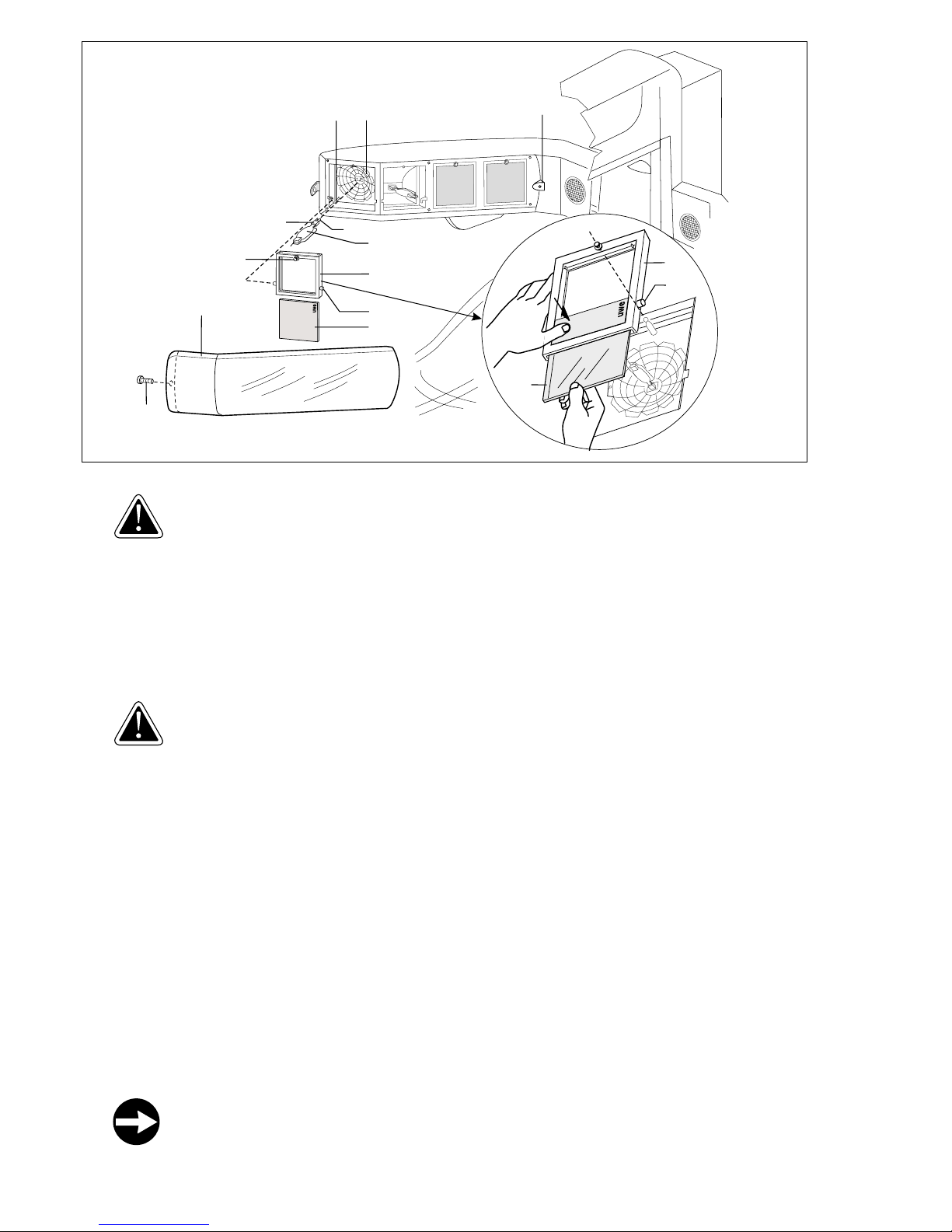
• Acrylic sheet tanning arms (43), installation and removal (picture 6)
Unscrew the flat-headed screw M 4 (65), with which the acrylic sheet (43) is fastened together over a square
on the light-casing. Then turn the acrylic sheet a little bit out and pull the acrylic sheet away forward in
longitudinal direction. When reinstalling, push the acrylic sheet of the lateral tanning arms over the fastening
wedge (104, picture 6).
Push the acrylic sheet of the upper tanning arm over the fastening wedge (44, picture 3) of the covering hood
(40). Lift the acrylic sheet in direction of the tanning arm. Tighten up again the flat-headed screw (65).
Al ways take care during the installation, that the acrylic sheet lays in the slot of the covering
hood (66).
65
43
79
68
72
70
104
99 71
102
69
68
70
72
67
Page 15

15
Function
Warnin
g
Warnin
g
Function
6.2 Exchanging the high pressure burner
The high pressure burner shall only be used with the XTT- filter disk.
The unit must not be operated if the disks are damaged or missing.
Danger of burning! Danger of lightning damage to the eyes!
The XTT-filter disk is protected by BreakSafe (see Section 8 BreakSafe)
Please exclusively use high pressure burners from uwe, because an exact centring of the centre of gravity of the light
in the reflector must be guaranteed.
If you immediately switch on again the burner, it will either not have capacity immediately or -depending on the
kind of type- it will not have full capacity, because it requires a cooling period of approx. 4 minutes.
Please only handle the high pressure burner with the metal clamp or with its pinch (102), and never
pull on the glass bulb.
Do not touch the glass bulb of the high pressure burner with your fingers. If this has inadvertently happened, clean
the fingerprints with a cloth soaked with alcohol.
Exchanging the high pressure burner in the tanning arms (picture 6)
Take down the acrylic sheet (43) according to the above detailed description.
Pull the Tenax lock (67) of the appropriate lamp housing downwards.
Warning! The disk holder can be lowered around 15 degrees.
Hold the disk holder (68) with both hands and lift the disk holder a little towards the tanning arm.
The bolt (70) slides out of the fixing point on both sides.
Pull off the disk holder from the front using both hands.
Hold the high pressure lamp by the rectangular base and press it out of the socket.
• Cleaning the Reflector
Clean the reflector (71) with a clean cloth soaked in alcohol.
• Fitting the High Pressure lamp
Hold the new high pressure lamp (69) by the base.
Insert the lamp into the holder.
Attention: The contact pins (79) of the socket have different diameters.
Please insert accordingly.
• Removing the Filter disk
Take the disk holder (68).
Hold the disk holder with both hands. Use both thumbs to lift the filter disk over the relevant adjustment
mechanism (angel bracket) and pull out the XTT filter disk (72).
• Cleaning the filter disk
Clean the filter disk with warm water. The water may contain a little detergent.
Dry the filter disk with a clean cloth.
Installing the filter disk
The tanning arm must not be used without the XTT filter disk.
The coated side of the XTT filter disk must face the lamp.
It must be possible to read the uwe logo on the filter disk from the bed.
Warning!
Install the XTT filter disk (72) nearest the user.
Install the XTT filter disk in the disk holder (68) as shown in Fig. 6.
Push the XTT filter disk over the adjustment mechanism (angle bracket).
The filter disk clips into place.
Hook the complete disk holder with the cleaned XTT filter disk into the lamp housing.
Move the disk holder towards the tanning arm until it touches the tanning arm.
The bolt of the micro switch (99) for the BREAKSAFE fuse is pressed back.
Press the Tenax lock (67).
The disk holder locks in place in the lamp housing.
Place the acrylic sheet (43) again.
Page 16
16
7
Warnin
g
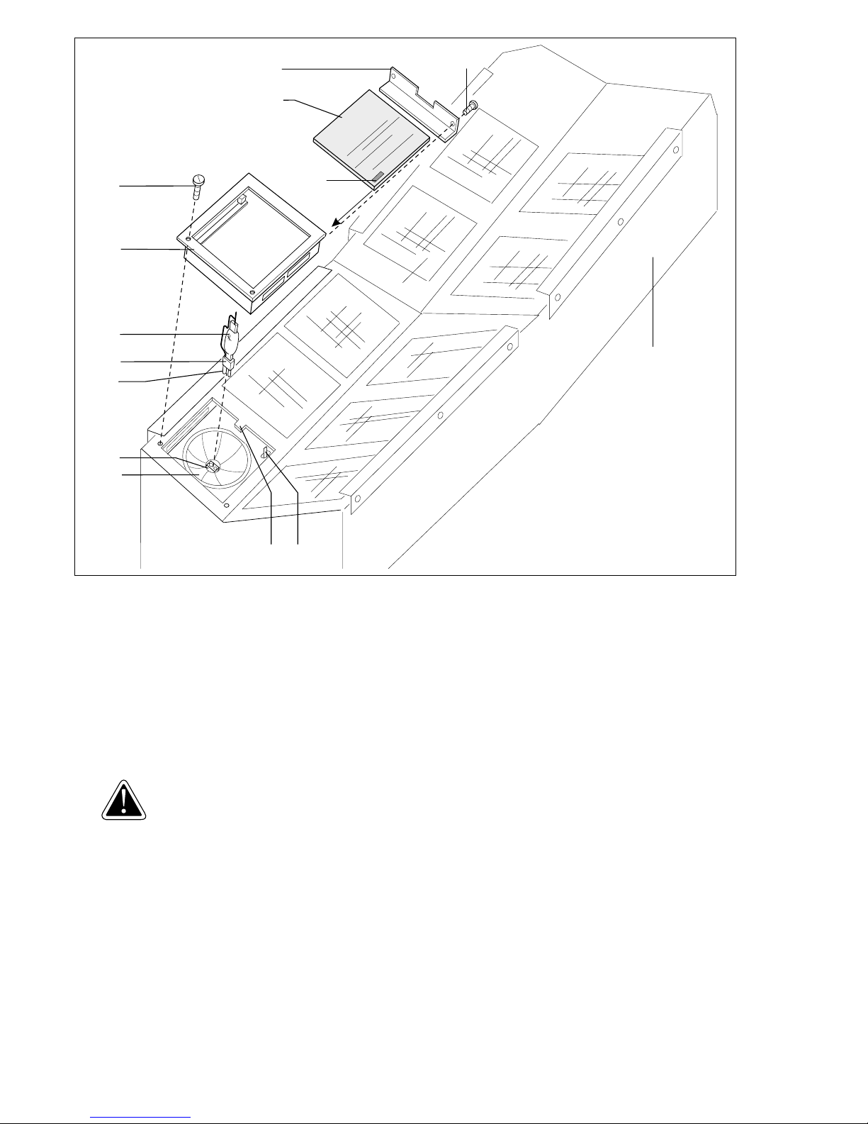
Exchanging of the high pressure burner in the lounger (picture 7)
Take down the acrylic sheet (1) according to the above detailed description. Unscrew the two oval-head and selftapping screws (74) out of the disk support (75). Disassemble the disk support by lifting the disk support on the side
showing to the foot, and then pull it out into that direction. The high pressure burner (76) is now opening accessible.
Hold the high pressure lamp by the rectangular base (102) and press it out of the socket (77).
• Cleaning the Reflector
Clean the reflector (87) with a clean cloth soaked in alcohol.
• Fitting the High Pressure lamp
Hold the new high pressure lamp by the base (102).
Insert the lamp into the holder (77).
Attention: The contact pins (79) of the socket have different diameters.
Please insert accordingly.
Cleaning the filter disk
Turn the two oval-head and self tapping screw (74) out of the disk support (75).
Take away the covering plate (98).
Pull out the XTT filter disk (72).
Clean the filter disk with warm water. The water may contain a little detergent.
Dry the filter disk with a clean cloth.
Installing the filter disk
The lounger must not be used without the XTT filter disk.
The coated side of the XTT filter disk must face the lamp.
It must be possible to read the little number (35, picture 7) of the filter disk if you stand in front of the light casing (6).
87
77
76
75
74
98
72
96 97
35
100
6
102
79
Page 17

17
Warnin
g
Warnin
g
Warning!
Install the XTT filter disk (72) nearest the user.
Install the XTT filter disk in the disk holder as shown in Fig. 7.
Introduce the clean XTT filter disk again into the disk support (75).
Screw in tight again the covering plate (98).
Hold the disk support in such a way, that the covering plate (98) shows in direction of the tripod.
Push the disk support, beginning from the foot side, into the gap, so that the flap (96) slides in the gap of the
covering plate.
Now the XTT filter disk press the micro-switch (97) into for the BreakSafe protection and the electri
cal circuit is closed. Therefore the XTT-filter disk is secured with BreakSafe.
Turn the screws (74) into and place the acrylic sheet lounger (1).
For replacement of the high pressure burners please turn to your specialized dealer or to the manufacturer of the
unit.
No responsibility will be taken over, whenever other than the genuine high pressure burners are installed.
6.3 Exchanging the illumination light (78, picture 3)
Take up the acrylic sheet lounger (1) on the foot a little bit, and pull away thereunder to the front direction the small
covering plate (57, picture 4). Then turn the illumination light (78) in any direction you with to for about 90 degrees,
until the contact pins (80) in the slot of the holder (81) are visible. Pull out the light. Hold the new bulb horizontally,
so that the contact pins lay horizontally one behind the other. In this position press the light bulb into the holder. Turn
the bulb for about 90 degrees, until the holder engages into. Place on again the covering plate (57).
6.4 Exchanging the Filter Mats
The air for cooling the unit is fed through micro filter mats on entry to the unit. Fluff, hair, dust particles, etc. are
filtered out in the filter so that it is only necessary to clean the components inside the unit e.g. such as filter plates
infrequently. The particles filtered out eventually clog the filter after extended use and thus reduce the effectiveness of the cooling of the unit. Therefore the filter mats should be renewed from time to time to avoid the unit
overheating. The interval between changes is dependant on the operating time and the amount of dirt.
Check up the filters in any case every 200 hours of operation. If the pores of the filters are half
Blocked, the filter must be exchanged.
Only use original filter mats from your specialist dealer or unit manufacturer.
• Exchanging the Filter Mats of the footrack (picture 4)
Take up a little bit the acrylic sheet lounger (1) at the foot and pull away thereunder to the front direction the
small covering plate (57). Inside of the covering plate the filter mat (82) is fastened with strip fastener. Take
away the filter mat and place on again the new filter mat.
• Exchanging the Filter Mats of the tanning arm (picture 3)
Remove the waved covering plate (83) on the respective tanning arm. For this purpose, push it in longitudinal
direction, until it slides with its flaps out of the large covering plate (66). Then pull out the wire clip (85), with
which the filter mats (86) are being supported. Remove the old filter mat and insert the new filter mat. Insert
again the wire clip. Place again the covering plate (83).
7 ADVICES
• Replacement of the high pressure burner
The performance of the high pressure burner gradually reduces without this being visually noticeable. You
must level this out with a longer sunbathing time. uwe recommends to exchange the high pressure burner after
approx. 400 hours of operation.
• Pipeframe
The two feet of the pipeframe (2) showing in direction of the assembly plates can be taken away one by one.
So that for service jobs you can easily reach the assembly plates, without having to disassemble the unit.
Page 18
18
8 TIPS FOR CORRECTING MINOR DEFECTS
Before you begin maintenance and repair work, you must disconnect the unit from the mains.
Repairs should only be performed by the uwe company or by authorised persons. Safety devices
must not be removed or disabled. After each repair, there must be made an examination of the unit,
which has to be reported.
Warnin
g
Warnin
g
Warnin
g
Warnin
g
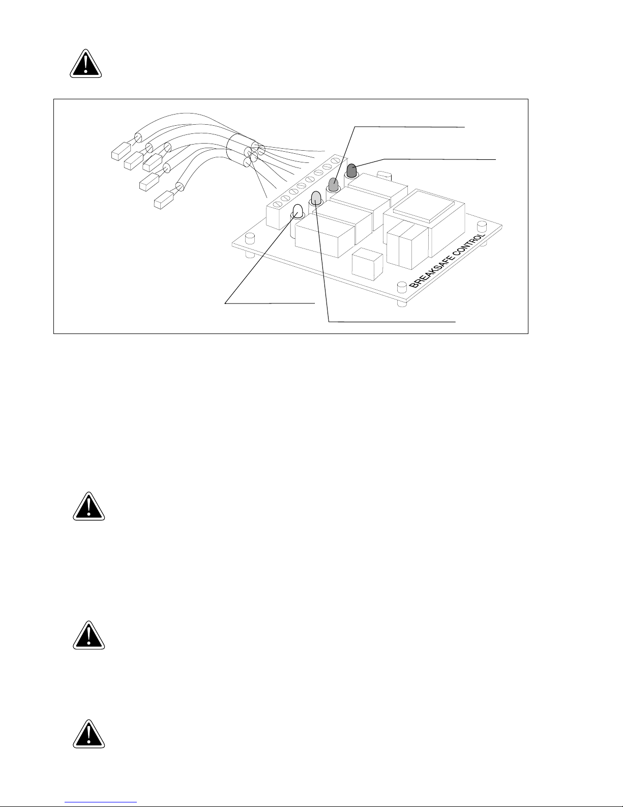
• BreakSafe
All XTT filter disks are secured by micro-switches, this means, that if the filter disks are o.k., the electrical cir
cuit is closed. If one filter disk breaks, then the electrical circuit will be interrupted and the unit can not be
operated any more. Then the broken filter disk must be exchanged. On the assembly plate control unit (20)
there is a platine with relais and four light-emitting diodes. One LED each belongs to the tanning arm and to
the lounger, respectively. The broken filter disk is located there, where the LED does not shine.
• The high pressure burners don’t switch on
Exchange the high pressure burner. If this doesn’t help, exchange the ignition unit. The ignition units of the high
pressure burners of the tanning arms are situated below the covering hood (66, picture 3). Dismantle for that
purpose the waved covering hood (83) and un-screw the covering hood (66). The ignition units of the highpressure burners of the lounger are located in the light-casing (6). These can be accessible, after disassembling the disk holder (75, picture 7) and the reflector (87). If this does not help, there is an electrical defect in
the unit.
Checking-up by uwe or by another firm named by uwe.
• The illumination light does not shine (exchange of starter, picture 4)
Take up a little bit the acrylic sheet lounger (1) at the foot and pull forward the small covering hood (57)
thereunder. The illumination bulb and the starter are now open accessible. Check up, if the bulb is inserted
correctly. Then check up, if the starter is located correctly. Take the starter out of the light by turning to the left
side, and then tighten it up again by turning to the right side. If the light does not shine, insert a new starter. If
this does not help, the bulb must be checked up. Insert a new bulb. If the light shines then, the old bulb was
defect and the error has been corrected. If it still does not shine, there is an electrical defect in the unit.
Check should be performed by uwe or by an authorised agent appointed by uwe.
• A tanning arm or the tanning lounger gets too hot
Check whether the air intake filters (Filter Mats) are clogged. In the case of direct air extraction ensure that
the warmed cooling air is fed to open air without any significant obstacle. There must be no blockage in the
hose or the ventilation duct since this will cause the unit to overheat.
Check should be performed by uwe or by an authorised agent appointed by uwe.
8
BREAKSAFE LED for base
BREAKSAFE LED forarm left
BREAKSAFE LED for arm right
plug connection of the
BREAKSAFE CONTROL
X 5a
x 6a
x 7a
x 8a/9a
BREAKSAFE LED
for arm top
arm top
arm right
arm left
base
1
2
4
5
6
7
8
3
Page 19

19
9 WASTE
• High pressure burner
The high pressure burner and the illumination light are special ref uses. They should not be thrown together with
the regular waste. The local offices will inform you, where the burner could be properly wasted.
• Unit
Faulty units should be disposed of according to local regulations.
10 CUSTOMER SERVICE ADDRESS
PC MARKETING
1040 WILT AVENUE
RIDGEFIELD, NJ 07657
1-800-FAST TAN
Page 20

20
ID-NR. 265 360 / 03/03
PC MARKETING
1040 WILT AVENUE
RIDGEFIELD, NJ 07657
1-800-FAST TAN
 Loading...