

Page 1
Model 5000
Installation Instructions
Attention
The Model 5000 design has changed as of August 1st, 2018.
Please read the instructions to ensure it is installed correctly.
Overview
● The Model 5000 provides 3 additional control wires
and a common connection ‘C’ between a thermostat
and indoor unit.
● The Model 5000 can not be used to extend the wiring
between and indoor and outdoor unit.
● The Model 5000 is compatible with most 24V AC
heating and cooling systems.
Electrical Safety
● This product is designed for use with a Class 2
transformer providing 23 to 28 volts.
● The total connected load must not exceed 2 amps.
● The connected load cannot operate at more than 30
volts (not designed for direct connection to 120 volt
equipment).
● To avoid risk of electrical shock or equipment damage,
disconnect power before beginning installation.
Sender Installation
The Sender is the smaller component and is installed inside
the wall behind the thermostat.
● Remove the thermostat from the wall.
● If the hole where the thermostat cable wires come
through is not big enough to fit the Sender, enlarge it.
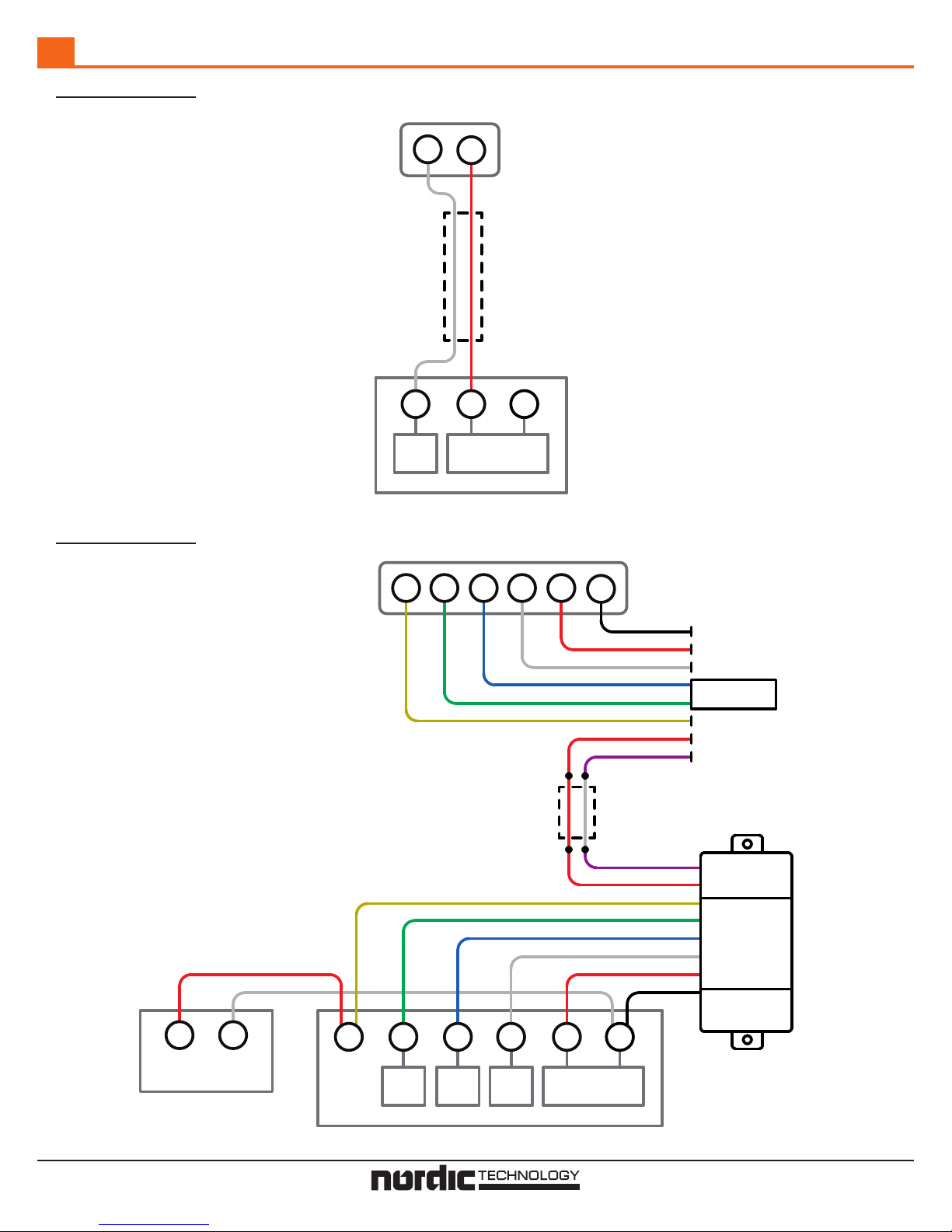
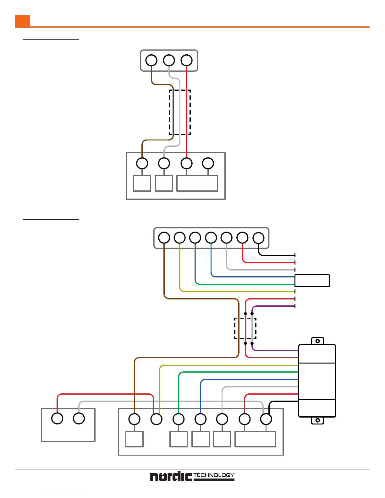
● Place the Sender in the wall and connect the wires to
the sub-base according to the wiring diagram (pages
3-4). The Sender will hang by its wires and does not
require any mounting.
● Install the thermostat on the wall.
Note: The Sender will produce a small amount of heat
while operating. Keep the Sender wires as long as possible
to maximize the distance between the Sender and
thermostat. Do not install the Sender in insulated walls.
Receiver Installation
The Receiver is the larger component and is installed inside
the cabinet of the indoor unit. If there is no space inside
the cabinet, the Receiver may be placed in any location
without exposure to high temperatures or water.
Connect the Receiver according to the wiring diagram for
the system (pages 3-4).
If the installation only has single stage heat, both the white
and blue wires can be connected to thermostat ‘W’ at the
Sender and equipment ‘W’ at the Receiver.
Some installations may require the Receiver voltage to
be adjusted. See ‘Setting the Receiver Voltage’ for more
information.
Setting the Receiver Voltage
The Model 5000 is factory set to be compatible with most
thermostats.
Differences in transformer voltage and thermostat power
consumption may require the Receiver to be adjusted. The
adjustable resistor located on the side of the case can be
turned to increase or decrease the Receiver voltage.
The voltage (DC) of the Receiver is measured between
the Receiver’s orange wire and transformer Common. It
is factory set for 0.30V (with a 24.0V transformer) while
disconnected from the thermostat.
Check each function on the thermostat (G, Y, W1, W2) to
see if the connected equipment turns on and off correctly.
If the equipment does not turn on when called, the
Receiver voltage may be too low. With the thermostat
calling for any function, increase the Receiver voltage until
the equipment activates. Set the voltage to 0.05V over the
minimum voltage the equipment activates at.
If the equipment does not turn off when the thermostat
stops calling, the Receiver voltage is too high. With the
thermostat not calling for any function, decrease the
Receiver voltage until the equipment turns off.
After the Receiver voltage has been set, check that all
equipment turns on and off correctly. The orange wire
should be taped back as it is no longer needed.
Operation
The Model 5000 has two channels, green and yellow, and
white and blue.
Applying 24V to the Sender’s green wire will output 24V
on the Receiver’s green wire.
Applying 24V to the Sender’s green and yellow wires will
output 24V on the Receiver’s green and yellow wires.
Applying 24V to the Sender’s white wire will output 24V
on the Receiver’s white wire.
Applying 24V to the Sender’s white and blue wires will
output 24V on the Receiver’s white and blue wires.
When 24V is applied to the Sender’s white or blue wires,
the yellow and green wires at the Receiver will not output
24V regardless of whether or not they are being called.
Contact Us
For installation assistance, our technical support line can
be reached at 1-800-775-4750, 9am-5pm PST, or emailed
at [email protected]
Page 1 of 4 www.fast-stat.com
Page 2
Troubleshooting Low Power Thermostats
1. Measure the transformer voltage to check if it drops
below 23V while in use. The Model 5000 may not
function properly outside of the 23-28 volt range and
the transformer may need to be replaced.
2. If applying 24V to ‘G’ on the Sender activates ‘W1’
on the Receiver, or vice versa, then the two wires
that connect the Sender and Receiver are crossed.
Disconnect the thermostat cable and swap the
connections.
3. At the thermostat, jumper ‘R’ to ‘G’ to activate the
fan. Jumper ‘R’, ‘G’, and ‘Y’ to activate the fan and
condenser. Jumper ‘R’ to ‘W1’ to activate first stage
heat. Jumper ‘R’, ‘W1’, and ‘W2’ to activate second
stage heat. If all functions work correctly when
jumpered, then the thermostat may not be configured
properly. If no functions operate there may be a break
in the thermostat cable.
4. If the Receiver is set to the highest voltage possible
and still does not activate the equipment when called,
then the power consumption of the thermostat is too
low. This can be fixed by adding a resistor in parallel
to the thermostat. See ‘Low Power Thermostats’ for
more information.
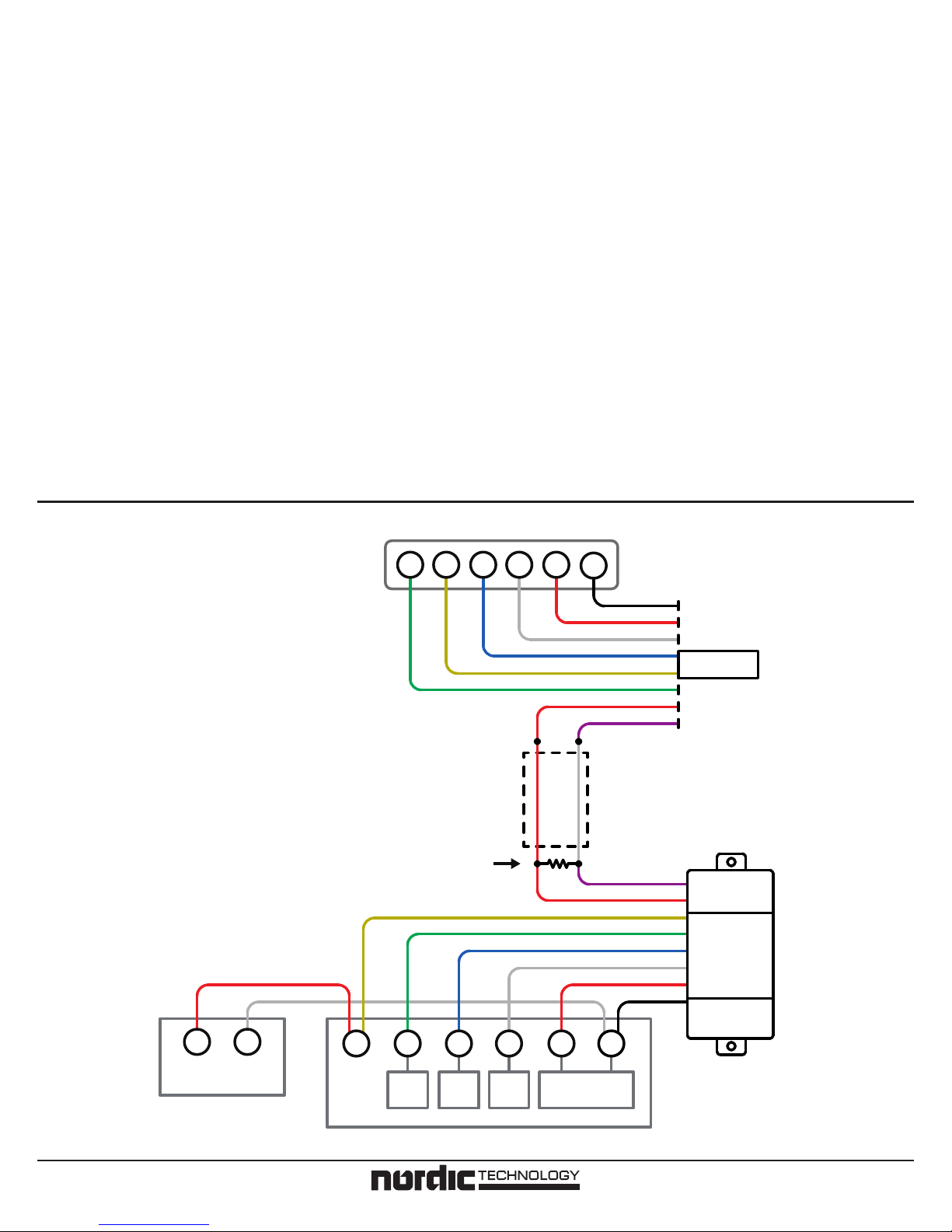
Some thermostats may not use enough power for the
Model 5000 to operate as intended. A resistor can be
added into the circuit to increase the amount of power
sent to the Receiver, as shown in the diagram below.
A 1000 Ω, 1W resistor is recommended, however similar
resistance values (750-1500 Ω) can be used. Ensure the
wattage of the resistor is 1W or more.
Low Power Thermostats: Adding a Resistor
G
Added
Resistor
Thermostat
Y
W1W2
R
C
Black
Red
White
Blue
Yellow
Green
Red
Purple
Sender
Thermostat
Cable
Receiver
Purple
Red
Yellow
Green
Blue
White
Black
FAST-STAT
Model 5000
Red
CY
Y
G
Fan
W2
Heat 2
W1
Heat 1
R
24V Transformer
C
Air Conditioner
Indoor Unit
Page 2 of 4 www.fast-stat.com
Page 3
Thermostat Cable with Two Wires
A
Before
Thermostat
After
W
Thermostat
Cable
W
Heat
Y
R
R
24V Transformer
Indoor Unit
Thermostat
G
C
W1W2
R
C
Black
Red
White
Blue
Green
Yellow
Red
Purple
Sender
Thermostat
Cable
Purple
Red
Yellow
Green
Blue
White
Red
Black
CY
Y
G
W2
W1
R
C
Receiver
FAST-STAT
Model 5000
Fan
Heat 2
Heat 1
24V Transformer
Air Conditioner
Indoor Unit
Page 3 of 4 www.fast-stat.com
Page 4
Thermostat Cable with Three or More Wires
B
Before
H
Thermostat
Cable
Thermostat
W
R
After
Humid.
Note: Any additional wires in the
thermostat cable can be connected
as normal. They do not interfere
with the Model 5000.
H
W
Heat
R
24V Transformer
Indoor Unit
Y
H
C
Thermostat
G
W1W2
Thermostat
Cable
R
C
Black
Red
White
Blue
Green
Yellow
Red
Purple
Sender
Receiver
Purple
Red
Yellow
Green
Blue
White
Red
Black
CY
H
Humid.
Y R C
G
Fan
W2
Heat 2
W1
Heat 1
24V Transformer
FAST-STAT
Model 5000
Air Conditioner
Indoor Unit
Page 4 of 4 www.fast-stat.com
 Loading...