

Fastrax IT530M Schematics

Rev. 1.0
Data Sheet
Fastrax IT530M
This document describes the electrical connectivity and functionality of the Fastrax IT530M
OEM GNSS Receiver.
August 14, 2012
Fastrax Ltd

Page 2 of 35
Ref. #
Publisher; Reference
(1)
Fastrax; NMEA Manual for Fastrax IT500 Series GPS receivers
(2)
Fastrax; Reflow_soldering_ profile.pdf
(3)
Fastrax; LOCUS manual for Fastrax IT500 Series
TRADEMARKS
Fastrax is a registered trademark of Fastrax Ltd.
All other trademarks are trademarks of MediaTek, Inc. or either of respective holders.
COPYRIGHT
© 2011 Fastrax Ltd
DISCLAIMER
This document is compiled and kept up-to-date as conscientiously as possible. Fastrax Ltd cannot, however,
guarantee that the data are free of errors, accurate or complete and, therefore, assumes no liability for loss or
damage of any kind incurred directly or indirectly through the use of this document. The information in this
document is subject to change without notice and describes only generally the product defined in the introduction
of this documentation. Fastrax products are not authorized for use in life-support or safety-critical applications.
Use in such applications is done at the sole discretion of the customer. Fastrax will not warrant the use of its
devices in such applications.
REFERENCES
2012-08-14
IT530M_Datasheet

Page 3 of 35
Rev.
Notes
Date
1.0
Initial documentation
2012-08-14
CHANGE LOG
2012-08-14
IT530M_Datasheet

Page 4 of 35
1 Contents
2 Overview .............................................................................................................................................................. 6
2.1 General ........................................................................................................................................................ 6
2.2 Block diagram .............................................................................................................................................. 7
2.3 Frequency Plan ............................................................................................................................................ 7
2.4 General Specifications ................................................................................................................................. 7
3 Operation ............................................................................................................................................................. 9
3.1 Operating Modes ........................................................................................................................................ 9
3.2 Full Power Mode ......................................................................................................................................... 9
3.2.1 Host port configuration .......................................................................................................................... 9
3.3 Power Management Modes ........................................................................................................................ 9
3.4 Self-Assistance EASY™ usage..................................................................................................................... 11
3.5 Server Assistance EPO™ usage .................................................................................................................. 11
3.6 Logger LOCUS usage .................................................................................................................................. 11
3.7 DGPS usage ............................................................................................................................................... 11
3.8 Backup State.............................................................................................................................................. 11
3.9 Reset State ................................................................................................................................................ 12
4 Connectivity ....................................................................................................................................................... 13
4.1 Signal Assignments .................................................................................................................................... 13
4.2 Power supply ............................................................................................................................................. 14
4.3 Host port configuration ............................................................................................................................. 15
4.4 Host port UART ......................................................................................................................................... 15
4.5 Reset input ................................................................................................................................................ 15
4.6 FORCE_ON input ....................................................................................................................................... 15
4.7 Antenna input ........................................................................................................................................... 16
4.8 Active GNSS antenna ................................................................................................................................. 16
4.8.1 Jamming Remover ................................................................................................................................ 16
4.9 PPS output ................................................................................................................................................. 17
4.10 Wakeup output ......................................................................................................................................... 17
4.11 Interrupt input EINT1 ................................................................................................................................ 17
4.12 UI_FIX signal .............................................................................................................................................. 17
4.13 32K/DR_INT signal ..................................................................................................................................... 18
4.14 Mechanical Dimensions ............................................................................................................................ 18
4.15 Suggested pad layout ................................................................................................................................ 19
5 Electrical Specifications ...................................................................................................................................... 20
5.1 Absolute Maximum Ratings ...................................................................................................................... 20
2012-08-14
IT530M_Datasheet

Page 5 of 35
5.2 DC Electrical specifications ........................................................................................................................ 20
5.3 AC Electrical characteristics ...................................................................................................................... 21
6 Manufacturing ................................................................................................................................................... 22
6.1 Assembly and Soldering ............................................................................................................................ 22
6.2 Moisture sensitivity ................................................................................................................................... 22
6.3 Marking ..................................................................................................................................................... 22
6.4 Tape and reel ............................................................................................................................................ 23
6.5 Environmental Specification ..................................................................................................................... 23
7 Reference design ............................................................................................................................................... 24
7.1 Reference circuit diagram ......................................................................................................................... 24
7.2 PCB layout suggestion ............................................................................................................................... 26
7.2.1 Other electronics on mother board ...................................................................................................... 26
7.2.2 Avoiding EMI ......................................................................................................................................... 27
8 AP530 Application board for IT530M ................................................................................................................ 28
8.1 Board Terminal I/O-connector .................................................................................................................. 28
8.2 Bill of materials ......................................................................................................................................... 29
8.3 AP530 Circuit diagram ............................................................................................................................... 31
8.4 AP530 layout and assembly ...................................................................................................................... 32
2012-08-14
IT530M_Datasheet

Page 6 of 35
2 Overview
2.1 General
The Fastrax IT530M is an OEM GNSS receiver module variant based on Fastrax IT530 with the Mediatek MT3333
chip that supports All-in-One GNSS hybrid navigation. The Fastrax IT530M receiver provides extremely low power
and very fast TTFF together with weak signal acquisition and tracking capability to meet even the most stringent
performance expectations in navigation with hybrid solution using signals from both GPS + Glonass GNSS systems.
Future GNSS systems like Galileo or Beidou can be supported with future firmware upgrade in GPS + Galileo or GPS
+ Beidou modes. The module has ultra small form factor 9.6x9.6 mm, height is 1.85 mm nominal (2.15 mm max)
and can be assembled with SMT reflow soldering.
The IT530M provides complete signal processing from antenna input to host port UART and location data output is
in NMEA protocol. The module requires a main and a backup power supply. The host port is configurable to UART
during power up. Host data and I/O signal levels are 2.8V CMOS compatible and inputs are 3.6V tolerable. The host
interface equals to the IT530 module variant excluding TIMER output signal (open drain), which is now FORCE_ON
input signal; the external power switch used with IT530 low power modes is now embedded in to IT530M.
The IT530M supports a new feature called AlwaysLocate™, which is an intelligent controller of the IT530M power
saving mode. Depending on the environment and motion conditions, the module can adaptively adjust the
navigation activity and fix rate based on measured velocity in order to achieve a balance in positioning accuracy,
fix rate and power consumption.
The module is also optionally self-assisted since the EASY™ (Embedded Assist System) ephemeris extension is
embedded in the software without any resources required from the host. The EASY™ data is stored on internal
flash memory and allows fast TTFF typ. 3 seconds over 3 days. Also EPO™ (Extended Prediction Orbit) server
generated extended ephemeris input is also supported, which allows fast TTFF 10 seconds typ. over 7/14 days.
The IT530M contains also an AIC (Active Interference Cancellation), which provides state-of-art narrow band (CW)
interference and jamming elimination up to 12 CW jammers < -80dBm.
The module also supports a logging feature called LOCUS, which enables automatic logging of position data to
internal flash memory. The logging capacity is >16 hrs typ. @ 15 sec storage interval.
The antenna input supports passive and active antennas with excellent out-of-band blocking rejection and
provides also an input for externally generated antenna bias supply.
This document describes the electrical connectivity and main functionality of the Fastrax IT530M OEM GNSS
Receiver module.
2012-08-14
IT530M_Datasheet
Page 7 of 35
Receiver
GNSS L1 C/A-code, SPS of GPS + Glonass, Galileo or Beidou
Chip set
Mediatek MT3333
Channels
99/33 (search/track)
Tracking sensitivity
-165 dBm typ. (GPS)
Navigation sensitivity
-165 dBm typ. (GPS)
Navigation sensitivity, re-acq.
-160 dBm typ. (GPS)
Navigation sensitivity, cold acq.
-148 dBm typ. (GPS)
Update rate
1 Hz (configurable up to 10 Hz)
Position accuracy (note 1)
3.0 m (67%) typ. Horizontal
5.0 m (67%) typ. Vertical
0.02 m/s (50%) typ. Velocity
Max altitude/velocity
<60,000 ft/<1,000 knots
Differential GPS
SBAS default (WAAS, EGNOS, MSAS, GAGAN, QZSS), RTCM
Time to First Fix, cold acq.
23 s typ. (note 1)
Time to First Fix, warm acq.
23 s typ. (note 1)
Time to First Fix, hot acq.
1 s typ. (note 1)
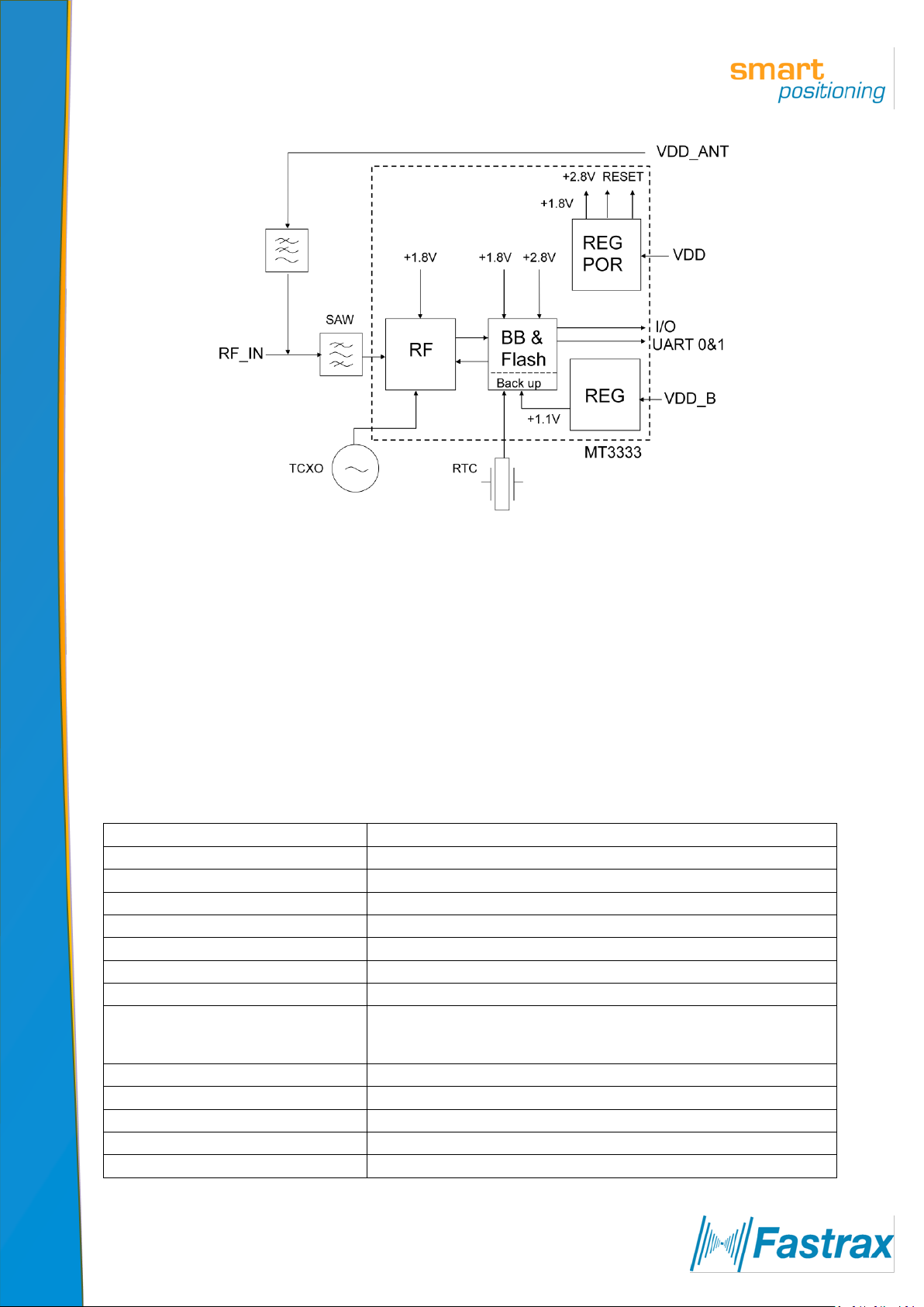
2.2 Block diagram
Figure 1 Block diagram
2.3 Frequency Plan
Clock frequencies generated internally in the Fastrax IT530M receiver:
Switched Mode Power Supply (in PWM and PFM modes)
32768 Hz Real Time Clock (RTC)
16.368 MHz Master Clock (TCXO)
3177.2 MHz Local Oscillator (LO) of the RF down-converter (GPS+Glonass mode)
LO/2, i.e. 1588.6 MHz of the RF down-converter (GPS+Glonass mode)
2.4 General Specifications
Table 1 General specifications
2012-08-14
IT530M_Datasheet

Page 8 of 35
Supply voltage, main VDD
+3.0 … +4.3 V
Supply voltage, backup VDD_B
+2.0 … +4.3 V
Power consumption, Full Power
57 mW typ. @ 3.3 V (note 2)
Power consumption, AlwaysLocate™
tbd mW typ. @ 3.3 V
Power consumption, Backup state
30 µW typ. @ 3.0 V
External RF amplifier net gain range
0… +30 dB
Storage temperature
-40°C…+85°C
Operating temperature
-40°C…+85°C
Host port configuration
UART
Host port protocol
NMEA-0183 rev. 3.01
Serial data format (UART)
8 bits, no parity, 1 stop bit
Serial data speed (UART)
115,200 baud (configurable 4,800... 921,600 baud)
PPS output
200 ms high pulse, rising edge +/-10 ns @ full second GPS epoch
Note 1: With nominal GNSS signal levels -130dBm.
Note 2: @ 1Hz navigation, GPS + Glonass mode, SBAS enabled, average over 24h
2012-08-14
IT530M_Datasheet

Page 9 of 35
3 Operation
3.1 Operating Modes
After power up the IT530M module boots from the internal ROM to Navigation Mode. Modes of operation:
Navigation Mode (Full Power)
o Power management system modes
Standby Mode
Backup State/Mode
Reset State
3.2 Full Power Mode
The module will enter Full Power (aka Navigation Mode) after first power up with factory configuration settings.
Power consumption will vary depending on the amount of satellite acquisitions and number of satellites in track.
This Mode is also referenced as Full On, Full Power or Navigation Mode.
Navigation is available and any configuration settings are valid as long as the main VDD and backup VDD_B power
supplies are active. When the main VDD and backup VDD_B supply is powered off, settings are reset to factory
configuration and receiver performs a cold start on next power up.
Suggestion is to keep the backup supply VDD_B active all the time in order to sustain on time, position and
ephemeris in the backup RTC and RAM. The main VDD supply can be used to control the module activity, i.e. when
VDD is switched off, the module operation is stopped.
Navigation fix rate can be configured by a NMEA command, see chapter 0. Note that baud rate must be set high
enough or message payload low enough in order to pass through all messages pending.
3.2.1 Host port configuration
Default host port is configured to UART Port 0 by keeping GPIO9 and GPIO10 floating (not connected) during
power up. UART Port1 is reserved for DGPS/RTCM protocol.
Default protocol for host communication is NMEA at 115,200 baud. Details on NMEA protocol can be found in
NMEA manual, ref (1). Default NMEA message output configuration: $GPGGA, $GNGSA, $GPGSV, $GPRMC,
$GPVTG and $GLGSV rate every second. The module supports also proprietary $PMTK input commands, see ref
(1). The message payload consists of $PMTK<cmd_id>,<data_field(s)>*<chk_sum><CR><LF>. Sample command:
$PMTK000*32<CR><LF>. For clarity <CR><LF> are not displayed in the following example messages but should be
added to the payload at host.
3.3 Power Management Modes
The IT530M module supports also low power operating modes for reduced power consumption:
1. Standby Mode: In this Mode the receiver stops navigation and internal processor enters standby state;
current drain at main supply VDD is reduced to 0.4 mA typ. Standby Mode is entered by sending NMEA
command: $PMTK161,0*28. Host can wake up the module from Standby Mode to Full Power Mode by
sending any byte via host port.
2. Backup Mode: (Support TBD) In this mode the receiver is configured to enter autonomously to Backup
State; the main power supply VDD shall be still active but supply is controlled internally on/off. In this
mode the receiver stays in Backup state (VDD and backup supply VDD_B active) and VDD current is
reduced to tbd mA. Backup Mode is entered by sending NMEA command: $PMTK225,4*2F. Host can
wake up the module via host control signal FORCE_ON signal toggle to high state (t>tbd ms).
2012-08-14
IT530M_Datasheet
Page 10 of 35
3. Periodic Mode: (Support TBD) This mode allows autonomous power on/off with reduced fix rate to reduce
average power consumption, see figure below; the main power supply VDD is controlled on/off externally
by a power switch that is controlled by the TIMER signal output, see reference circuit in chapter 7.1.
Periodic Mode is entered by sending the following NMEA command:
$PMTK225,<Type>,<Run_time>,<Sleep_time>,<
where Type=1 for Periodic Backup Mode; Run_time = Full Power period (ms); Sleep_time =
Standby/Backup period (ms);
acquisition fails during the Run_time;
2nd
_run_time = Full Power period (ms) for extended acquisition in case GNSS
2nd
_sleep_time = Standby/Backup period (ms) for extended sleep in
2nd
_run_time>,<
2nd
_sleep_time>*<checksum><CR><LF>,
case GNSS acquisition fails during the Run_time. Example: $PMTK225,1,3000,12000,18000,72000*16 for
periodic Mode with 3 sec Navigation and 12 sec sleep in Backup state. Acknowledge response for the
command is $PMTK001,225,3*35. The module can exit Periodic Mode by command $PMTK225,0*2B sent
just after the module has been wake up from previous sleep cycle.
Figure 2 Periodic Mode
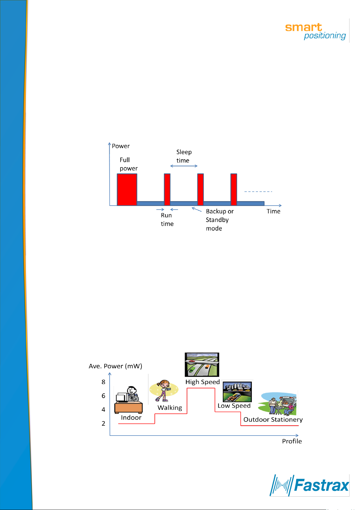
4. AlwaysLocate™ (Support TBD) is an intelligent controller of the Periodic Mode; the main power supply VDD
is controlled on/off externally by a power switch that is controlled by the TIMER signal output, see
reference circuit in chapter 7.1. Depending on the environment and motion conditions, the module can
autonomously and adaptively adjust the parameters of the Periodic Mode, e.g. on/off ratio and fix rate to
achieve a balance in positioning accuracy and power consumption, see figure below. The average power
drain can vary based on conditions; typical average power is 3 mW. Associated profiles are: High and Low
Speed, Walking, Outdoor Static and Indoor. AlwaysLocate™ Mode is entered by sending the following
NMEA command: $PMTK225,<Mode>*<checksum><CR><LF>, where Mode=9 for AlwaysLocate™ in
Backup Mode. Example: $PMTK225,9*22. Acknowledge response for the command is
$PMTK001,225,3*35. The module can exit AlwaysLocate™ Mode by command $PMTK225,0*2B sent just
after the module has been wake up from previous sleep cycle.
2012-08-14
IT530M_Datasheet
Figure 3 AlwaysLocate™ Mode

Page 11 of 35
The module can control the embedded VDD power switch autonomously only after the IT530M is set to Periodic,
Backup or to AlwaysLocate™ mode by a NMEA command.
Note also that first fix position accuracy can be somewhat degraded in Power Management Modes when
compared to Full Power operation. User can improve the position accuracy by taking the 2nd or 3rd fix after waking
up.
User can exit low power Modes 3… 4 to Full Power by sending NMEA command $PMTK225,0*2B just after the
module has woke up from previous sleep cycle.
3.4 Self-Assistance EASY™ usage
The IT530M module self-assistance (Support TBD) uses EASY™ (Embedded Assist System) ephemeris extension,
which is embedded in the software without any resources required from the host. The EASY™ data is stored on
internal flash memory and allows fast TTFF typ. 3 seconds over 3 days and is enabled by default.
Allow the receiver to navigate at least for 5 minutes with good GNSS satellite visibility in order to collect broadcast
ephemeris and to process necessary information.
3.5 Server Assistance EPO™ usage
The IT530M module supports also input from server generated EPO™ file (Extended Prediction Orbit, i.e.
ephemeris extension for GPS signals only), which can be transferred from a FTP server and allows fast TTFF with
GPS signal typ. 10 seconds over 7/14 days. Contact Fastrax support for details on EPO FTP server usage.
3.6 Logger LOCUS usage
The IT530M module supports (Support TBD) embedded logger function called LOCUS and when enabled it can log
position information to internal flash memory; default log interval is 15 seconds that provides typically > 16 h log
capacity. The LOCUS can be enabled by NMEA command $PMTK185,0*22. Contact Fastrax support for details on
Locus usage, see ref (3).
3.7 DGPS usage
By default DGPS/SBAS navigation mode is enabled. The search for suitable SBAS satellite signal is automatic.
The host may either enable DGPS/RTCM navigation mode by sending command ‘Set DGPS Data Source to RTCM’
$PMTK301,1*2D. The UART Port1 is used for RTCM message input at 9600 baud.
Note that DGPS usage is only supported with GPS system at 1 Hz navigation rate in Full Power mode. Note also
that acquiring necessary DGPS correction parameters may take up to 1 minute prior DGPS fix status is achieved,
which is indicated in the $GPGGA message, Fix Valid Indicator. Note also that DGPS corrections do not provide
corrections against multipath errors that are local; thus accuracy is not necessary improved in urban
environments.
3.8 Backup State
Backup State means a low quiescent (10 µA typ. at VDD_B) power state where receiver operation is stopped; only
the backup supply VDD_B is powered on while the main supply VDD is switched off by host (or autonomously by
IT530M, see also chapter 3.3). Waking up from Backup State to Full Power is controlled by host by switching on
the VDD supply.
After waking up the receiver will use all internal aiding like GNSS time, Ephemeris, Last Position etc. resulting to a
fastest possible TTFF in either Hot or Warm start modes.
During Backup State the I/O block is powered off; thus suggestion is that host shall force it’s outputs to low state
or to high-Z state during Backup state to minimize small leakage currents (<10 µA typ.) at receiver’s input signals.
2012-08-14
IT530M_Datasheet
 Loading...