

Page 1

3VBA V
3VBA V
User Manual V1.0
Copyright 2000 Publishing. All Rights Reserved.
This manual, software and firmware described in it are copyrighted by
their respective owners and protected under the laws of the Universal
Copyright Convention. You may not reproduce, transmit, transcribe,
store in a retrieval system, or translate into any language, in any form or
by any means, electronic, mechanical, magnetic, optical, chemical,
biological, molecular, manual, or otherwise, any part of this publication
without the express written permission of the publisher.
All products and trade names described within are mentioned for
identification purpose only. No affiliation with or endorsement of the
manufacturer is made or implied. Product names and brands appearing
in this manual are registered trademarks of their respective companies.
The information published herein has been checked for accuracy as of
publishing time. No representation or warranties regarding the fitness
of this document for any use are made or implied by the publisher. We
reserve the right to revise this document or make changes in the
specifications of the product described therein at any time without
notice and without obligation to notify any person of such revision or
change.
Print in T aiwan.
Page 2

Item Checklist
Before you begin installing your motherboard, please make
sure that the following materials have been shipped:
This mainboard comes in a sturdy cardboard shipping
carton, which should contain the following items:
• The main board.
• This user manual.
• One Floppy disk drive cable.
• One Ultra DMA/66 IDE cable.
• Software utilities.
If you discover damaged or missing items, please contact
your retailer.
User’s manual Version : 1.00
Release Date : JUL. 2000
Page 3

9VBAV User’s Manual
3-1 Introduction...........................................…………………………………..... 3-1
9VBAV User’s Manual
CONTENTS
1 Introduction ................................................................................................ 1-1
1-1 Introduction ...................................................................................... 1-1
1-2 Specifications................................................……. …………………… 1-1
1-3 PACKAGE CHECKLIST …………………................................................ 1-3
1-4 Block Diagram .............................................................................. 1-4
1-5 Main Board Layout with Default Setting ……....................................... 1-5
1-6 Static Electricity Precautions................................................................... 1-6
2 Installation Procedures ................................................................................. 2-1
2-1 Setting System Jumpers .............................................……................. 2-1
3-2 Main Menu …..........................................……………........................... 3-4
3-3 Standard CMOS Features ............................................................. 3-6
3-4 Advanced BIOS Features............................................…….............. 3-10
3-5 Advanced Chipset Features............................................................. 3-15
3-6 Integrated Peripherals ………........................................................ 3-18
3-7 Power Management Setup ................................................................ 3-21
3-8 PnP/PCI Configuration ...........................................................……....... 3-26
3-9 PC Health States ………..................................................………....... 3-28
3-10 Frequency / Voltage Control ……........................................................3-29
3-11 Defaults Menu ………………..………………………..…………………..3-30
3-12 PASSWORD SETTING ….............................................……......….3-31
3-13 Exit Selecting ……………………........................................................3-32
2-2 System Memory (DIMM) …….............................................................. 2-4
2-3 Central Processing Unit (CPU) ….....................…………........................ 2-5
2-4 Expansion Cards ................................................................................... 2-5
2-5 External Connectors .............................................………..................... 2-6
2-6 Power Connection Procedures …................................................... 2-15
3 AWARD BIOS Setup ................................................................................. 3-1
I1
4 Software Driver Installation ..................................................................... 4-1
4-1 UPDATED PRODUCT INFORMATION .................................................... 4-1
4-2 Install Audio Driver ............................................................................. 4-6
4-3 Install Audio Driver(WDM) ................................................................. 4-8
5 Anti-Virus software installation ……………………………………………..… 5-1
I2
Page 4
3VBAV User’s Manual
Introduction
1-1 Introduction
The motherboard is a high-performance, low-cost motherboard which supports the
Intel FC-PGA PIII and Socket 370 microprocessor . System memory bank supports
3 DIMM socket. Memory up to 768MB 100MHZ & 133MHZ SDRAM.
On-board includes 4X AGP SLOT, Stereo sound, ATX power, Super I/O, 2 Ultra
DMA/66 EIDE interfaces, 4 USB ports, 4 PCI Expansion slots, and 1 AMR slot
2 ISA Slots.
1-2 Specifications
CPU
- Supports FC-PGA and Socket-370 (Intel Pentium III TM
and Celeron TM ) processors.
- 2 nd level Cache Depend on CPU.
- Coppermine FCPGA packaged Processor.
- VIA Cyrix III Processor.
- Supports 66 / 100 / 133 MHz CPU Front Side Bus (FSB).
Chipset
- VIA VT82C694X North Bridge.
- VIA VT82C686A South Bridge.
Clock Generator
- Supports 66 / 100 / 133 / 140* / 150* MHz.
(“*” means frequency can be adjusted, and subject to
different configuration)
Memory
- 3 x 168-pin DIMM Sockets.
- Supports 100MHZ & 133MHZ SDRAM 16MB~1.5GB.
- Supports only 3.3V SDRAM DIMM.
- Supports Virtual Channel Memory(VCM) memory.
Audio
- SoundBlaster Pro Hardware and Direct Sound Ready
AC97 Digital Audio Controller.
- Hardware SoundBlaster Pro for Windows DOS box and
real-mode DOS legacy compatibility.
- Supports two channel speaker mode.
3VBAV User’s Manual
- MPU-401 game/MIDI port and Sound blaster®16
compatible.
I/O Control
- Integrated Super IO Controller in the VT82C686A.
Expansion Slot
- Four 32-bit PCI slots support Master mode.
- One 4X AGP Slot.
- Two ISA Slot.
- One Audio Modem Riser (AMR) slot.
I/O Interface
- PCI Bus master IDE interface on board with two
connectors support 4 IDE devices in 2 channel, the PCI
IDE Controller supports PIO Mode 0 to Mode 4, Bus
master IDE DMA Mode 2 and Ultra DMA 33/66.
- On board super Multi-I/O chip that support 2 serial port
with 16550 Fast UART compatible, 1 parallel port with
EPP and ECP capabilities, and a floppy disk drive
interface.
- On board support PS/2 mouse Connector.
- On board support PS/2 Keyboard Connector.
- On board 4 USB ports.
- On board IrDA connector.
- Floppy port supports 2 FDD with 360K, 720K,1.2M,1.44M
and 2.88M bytes ,Supports LS-120 floppy disk device.
Other Function
- Support Modem Ring Power On.
- Supports Keyboard, and WOL (Wake On LAN).
Power Supply
- On board 3V, 5V and 12V 20-pin ATX power connector.
- Use switching regulator to support CPU core voltage.
Hardware Monitor
- CPU/Power Supply/Chassis Fan Revolution detecting.
- CPU Fan Control.
- System Voltage Detect.
- Display Actual Current Voltage.
1-1
1-2
Page 5
3VBAV User’s Manual
BIOS
- Licensed AWARD BIOS, 2M bit FLASH RAM.
- ACPI ready for PC98/Windows 98.
- System BIOS supports ACPI function and Green feature
function, DMI, Plug and Play Flash ROM.
Form factor
- ATX Form Factor.
- Dimensions 305mm x 190mm, 4 layers PCB.
DRIVERS
- VIA 4-In-1 VIA SERVICE PACK.
- AC97 audio sound drivers.
- VIA HARDWARE MONITOR Applications.
- DirectX 7.
1-3 PACKAGE CHECKLIST
If you discover any item below was damaged or lost, please contact your vendor.
◇ The main board.
◇ This user manual.
◇ One Floppy disk drive cable.
◇ One Ultra DMA 66 IDE cable.
◇ Software utilities.
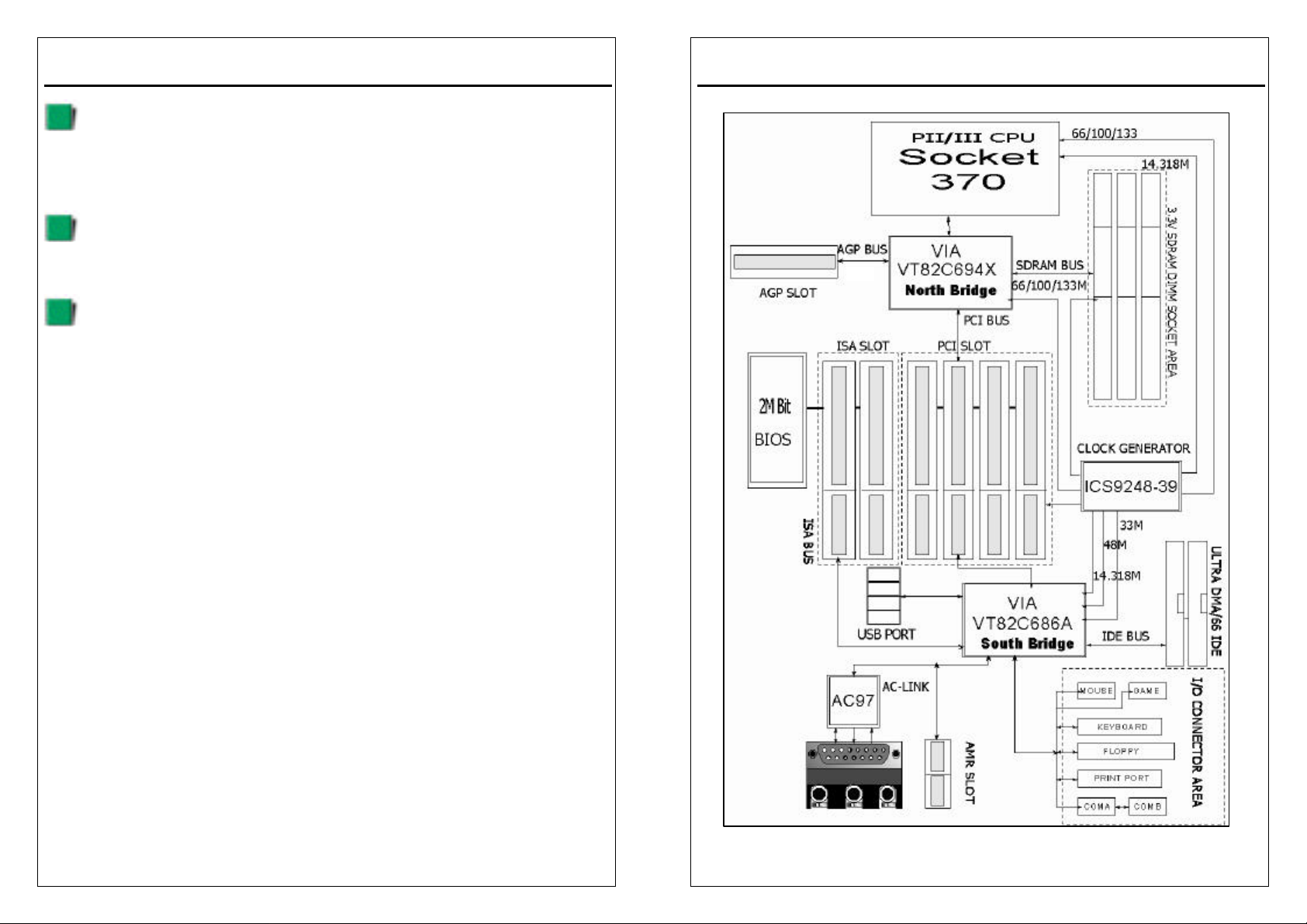
1-4 Block Diagram
3VBAV User’s Manual
1x/2x/4x
1-3
1-4
Page 6
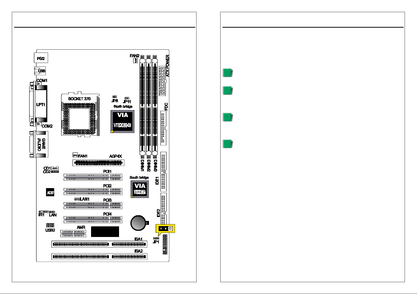
1-5 Main Board Layout with Default Setting
System default support INTEL PIII(133MHZ FSB)
Keyboard Wake up Enable.
1-5
3VBAV User’s Manual
3VBAV User’s Manual
1-6 Static Electricity Precautions
Static electricity can easily damage your motherboard.
Observing a few basic precautions can help you safeguard against damage that
could result in expensive repairs. Follow the measures below to protect your
equipment from static discharge:
Keep the motherboard and other system components in their antistatic
packaging until you are ready to install them.
Touch a grounded surface before you remove any system component from
its protective antistatic packaging. A grounded surface within easy reach is
the expansion slot covers at the rear of the system case. or any other
unpainted portion of the system chassis.
During configuration and installation, touch a ground surface frequently to
discharge any static electric charge that may build up in your body. Another
option is to wear a grounding wrist strap.
When handling a motherboard or an adapter card, avoid touching its
components. Handle the motherboard and adapter cards either by the
edges or by the mounting bracket that attaches to the slot opening in the
case.
1-6
Page 7
3VBAV User’s Manual
Installation Procedures
The mainboard has some user-adjustable jumpers on the board that allow you to
configure your system to suit your requirements. This chapter contains information
on the various jumper settings on your mainboard.
To set up your computer, you must complete the following steps:
1. Setting system jumpers.
2. Install RAM modules.
3. Install CPU & FAN.
4. Connect ribbon cables, cabinet wires, and power supply.
5. Set up BIOS.
6. Set up system drivers and utility.
2-1 Setting System Jumpers
You may configure your motherboard to match the needs of your applications by
setting jumpers. A jumper is the simplest kind of electrical switch. It consists of two
metal pins and a small metal clip (often protected by a plastic cover) that slides
over the pins to connect them. To “close” a jumper, you connect the pins with the
clip. To ”open ” a jumper, you remove the clip. Sometimes a jumper will have three
pins, labeled 1, 2, 3. In this case you would connect either pin 1 and 2 or 2 and 3.
OPEN CLOSED CLOSED 2-3
2-1
3VBAV User’s Manual
The jumper settings are schematically depicted in this manual as follows:
A pair of needle-nose pliers may be helpful when working with jumpers.
Note: When you open the jumper, attach the plastic jumper cap to one of the pins
so you won’t lose it.
Warning: Always completely disconnect the power cord from your board
whenever you are working on it. Do not make connections while the power is on
because sensitive electronic components can be damaged by the sudden rush of
power.
Always ground yourself to remove any static charge before touching the board.
Modem electronic devices are very sensitive to static electric charges. Use a
grounding wrist strap at all times. Place all electronic components on a
static-dissipative surface or in a static-shielded bag when they are not in the
chassis.
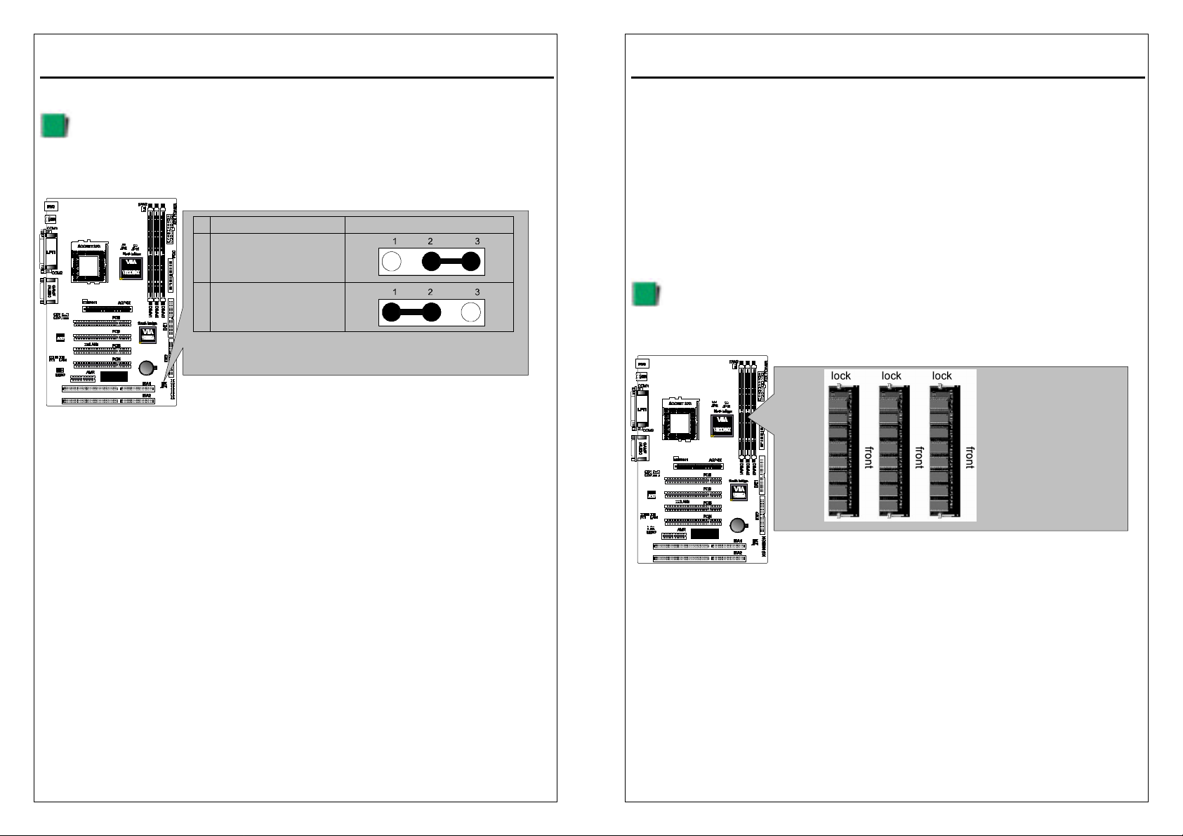
CPU External Frequency Settings:(JP8)
The Motherboard supports Intel Socket 370 CPUs with 66MHz or 100MHz or
133MHz external frequency. Setting the jumper according to the external
frequency of the CPU you are going to install on the motherboard.
BIOS auto-detect CPU
Frequency(66/100MHZ)
1
PII and Celeron and Cyrix
III setting
BIOS auto-detect CPU
Frequency(66/100/133M)
2
PIII and Cyrix III setting
[Default]
states JP8
2-2
Page 8
3VBAV User’s Manual
Clear CMOS:(JP1)
To clear the data stored in the CMOS, always turn off the computer first, then
remove this jumper to 2-3 pin to clear the CMOS. The jumper should be set to 1-2
pin (3V battery back up) before turn on the computer.
1 Clear CMOS
2 Normal [Default]
* Clear CMOS must be turn off the AC power first.
states JP1
3VBAV User’s Manual
2-2 System Memory (DIMM)
The motherboard supports up to 1.5GB 100/133MHz SDRAM. No hardware or
BIOS setup is required after adding or removing the system memory.
Note:
1.The motherboard uses only Dual Inline Memory Modules (DIMMs). Sockets are
available for 3.3Volt (power level) Synchronous Dynamic Random
Access Memory (SDRAM).
2.The 100/133Mhz compliant SDRAM must be used because of the strict timing
issues involved under this speed.
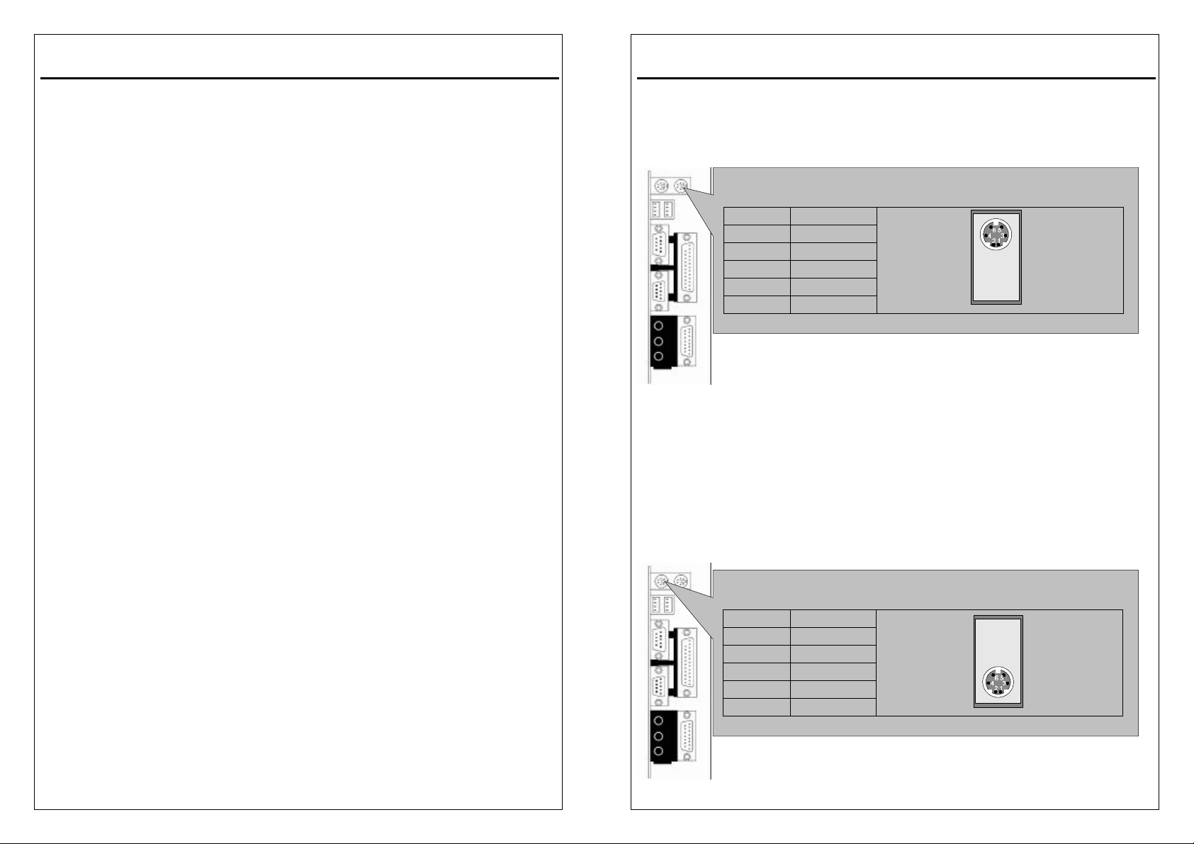
Installing system Memory
Insert the DIMM module(s) as shown. Because the number of pins are different on
each side of the breaks, the module will be fitted only in the orientation shown.
The DIMM must be 3.3V for this motherboard.
2-3
2-4
Page 9
3VBAV User’s Manual
2-3 Central Processing Unit (CPU)
The Motherboard provides a ZIF Socket 370. The CPU that came with the
motherboard should have a fan attached to it to prevent overheating. If this in not
the case, then purchase a fan before you turn on your system. Be sure that there
is sufficient air circulation across the processor heat sink, or the processor could
overheat and damage both the processor and the motherboard.
To install a Socket 370 CPU, first turn off your system and remove its cover.
Locate the ZIF socket and open it by first pulling the lever sideways away from the
socket then upwards to a 90-degree angle. Insert the CPU with the correct
orientation as shown. The notched corner should point towards the end of the
lever. Because the CPU has a corner pin for two of the four corners, the CPU
will only be fitted in the orientation as shown. The picture is for reference only: you
should have a CPU fan that covers the topside of the CPU. With the added weight
of the CPU fan, no force is required to insert the CPU. Once completely inserted,
close the socket lever while holding down the CPU.
2-4 Expansion Cards
Always unplug the power supply when adding or removing expansion cards or
other system components. Failure to do so may cause severe damage to both
your motherboard and expansion cards.
Expansion Card Installation Procedure The Motherboard has 4 PCI and 1 AMR
and 1 AGP and 2 ISA expansion slots. You may install up to 4 PCI cards and 1
AGP card and 1 AMR card and 2 ISA cards on this motherboard. To install the
PCI cards or AMR card, please follow the following procedure:
1. Read the documentation for your expansion card and make any necessary
hardware or software settings for you expansion card, such as jumpers or
switches.
2. Remove your computer system cover and the bracket plate with screw on the
slot you intend to use. Keep the bracket for possible future use.
3.Carefully align the card connectors and press firmly.
4.Secure the card on the slot with the screw you removed above.
5.Replace the computer system cover.
6.Setup the BIOS if necessary.
7.Install the necessary software drivers for your expansion card.
Note: To install the AMR Card. You should set the “AC97 Modem” as ”auto” in the
”INTEGRATED PERIPHERALS” of the BIOS Setup.
2-5
3VBAV User’s Manual
2-5 External Connectors
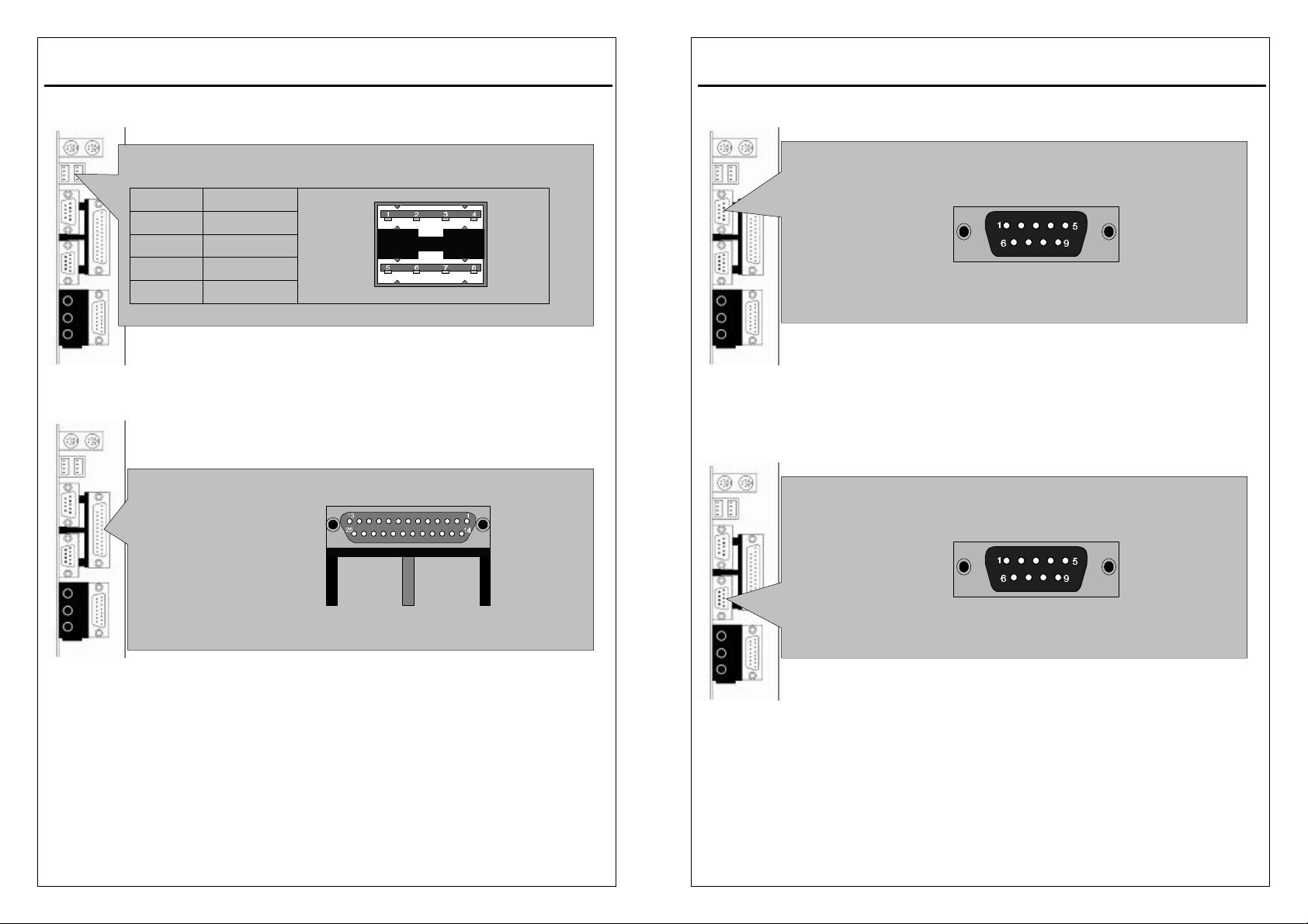
1.PS/2 Mouse Connector:
The motherboard provides a mini-DIN mouse connector, which supports a PS/2
style mouse.
2.PS/2 Keyboard Connector:
This connector is for a standard keyboard using a PS/2 plug (mini DIN). This
connector will not allow standard AT (large DIN) keyboard plugs. You may use a
DIN to mini DIN adapter on standard AT keyboards. In some applications, the
keyboard is not present, the standard BIOS will report an error or failure during the
Power-On Self Test (POST) after resetting the PC. You may select “All, But
Keyboard” under the ”Halt On” in “Standard CMOS SETUP” of BIOS SETUP.
This allows the system non-keyboard operation without the system halting during
the POST.
PS/2 Mouse Connector
PC99 Color : Green
PIN FUNCTION
1 DATA
2,6 N.C
3 GND
4 +5V
5 CLOCK
PS/2 Keyboard Connector
PC99 Color : Purple
PIN FUNCTION
1 DATA
2,6 N.C
3 GND
4 +5V
5 CLOCK
2-6
Page 10
3VBAV User’s Manual
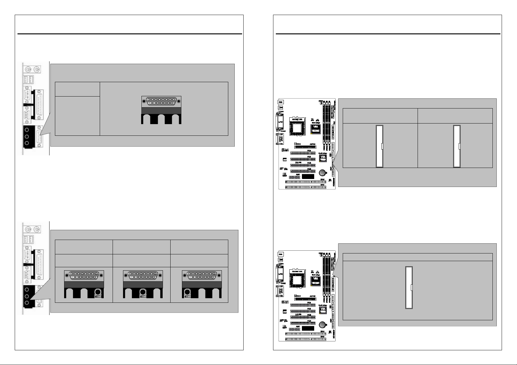
3.Universal Serial BUS (USB) Ports 1 & 2:
There are two USB ports on this motherboard for connecting USB devices.
4.Parallel Port Connector:
Normally, the parallel port is used to connect the system to a printer.
Universal Serial BUS (USB) Ports 1 & 2
PC99 Color : Black
PIN FUNCTION
1,5 +5V
2,6 USB3,7 USB+
4,8 GND
Parallel Port Connector
PC99 Color : Burgundy
3VBAV User’s Manual
5.Serial Port COM1 connector:
The COM1 port is ready for a mouse or other serial devices.
6.Serial Port COM2 connector:
The COM2 port is ready for a mouse or other serial devices.
Serial Port COM1 connector
PC99 Color : Turquoise
Serial Port COM2 connector
PC99 Color : Turquoise
2-7
2-8
Page 11
3VBAV User’s Manual
NOTE: Orient the red markings on the IDE ribbon cable to
7.Joystick/MIDI connector:
You may connect game joysticks or game pads to this connector for playing
games. Connect MIDI devices for playing or editing audio.
8.Audio Port connectors:
The Audio Port Connectors on the motherboard are standard1/8”GAME-AUDIO
connectors. Line Out (lime) can be connected to headphones or POWERED
speakers. Line In (light blue) allows tape players or other audio sources to be
recorded by your computer or played through the Line Out (lime). Mic (pink)
allows microphones to be connected for inputting voice.
Joystick/MIDI connector
JOYSTICK
PORT
PC99 Color:
Gold
Audio Port connectors
MICROPHONE IN
PC99 Color :
Pink
PC99 Color : Light
AUDIO
IN
Blue
AUDIO
OUT
PC99 Color : Lime
3VBAV User’s Manual
9.Primary/Secondary IDE Connectors(IDE1 and IDE2)
The motherboard supports up to four IDE devices, including CD-ROM drives, tape
backup drives, Hard Disk Drives, and other IDE devices. After connecting the
single end to the board, connect the two plugs at the other end to your hard
disk(s). If you install two hard disks, you must configure the second drive to Slave
mode by setting its jumper accordingly. Please refer to your hard disk
documentation for the jumper settings. (Pin 20 is removed to prevent the users
inserting the IDE devices in the wrong orientation when using ribbon cables with
pin 20 plugged).
Note: Ultra DMA/66 IDE devices must use an 80-wire IDE cable or else devices
will automatically be limited to Ultra DMA/33 mode.
10.Floppy Disk Drive Connector(FDC)
You can attach up to two floppy drives to the motherboard. After connecting the
single end to the board, connect the two plugs on the other end to the floppy
drives. The drive A: should be connected on the end and the drive B: in the
middle.
Primary/Secondary IDE Connectors
Primary IDE Connectors
Color : Blue
PIN1
pin 1
Secondary IDE Connectors
Color : White
PIN1
Floppy Disk Drive Connector
Floppy Disk Drive Connector Color : White
NOTE: PIN1
Orient the red markings on the floppy ribbon cable to pin 1
2-9
2-10
Page 12
3VBAV User’s Manual
Note: Pin 5 is removed to prevent the users inserting the Floppy Disk Drive in the
wrong orientation when using ribbon cables with pin 5 plugged.
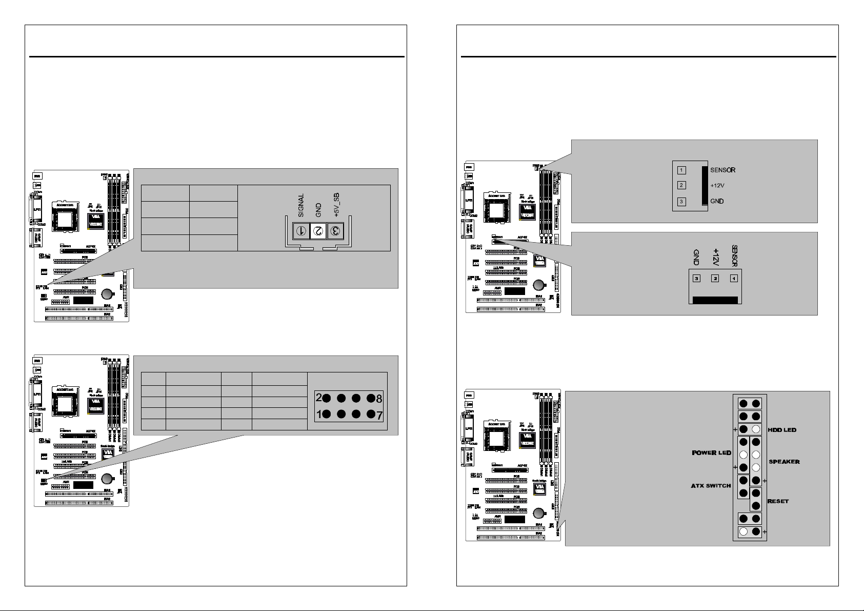
11.Wake-On-LAN(WOL)/Wake-On-Modem(WOM) connectors(JP3)
The Wake-On-LAN and Wake-On-Modem connectors connect to a LAN card and
Modem card respectively with a Wake-On-LAN/Wake-On-Modem output. The
connectors power up the system when a wakeup packet or signal is received
through the LAN card/Modem card.
12.Universal Serial BUS (USB) PIN Header(USB2)
There are two USB PIN Header on this motherboard for connecting USB devices.
Wake-On-LAN(WOL) connectors
PIN FUNCTION
1 SIGNAL
2 GND
3 +5V_SB
NOTE : The ATX power supply supports larger than 720mA
5V Standby current.
Universal Serial BUS (USB) PIN Header
PIN FUNCTION
1 VCC 2 GND
3 USB- 4 USB+
5 USB+ 6 USB7 GND 8 VCC
Caution: Pls. Compare each pin assignment of USB cable with
that of USB PIN header listed above. If both are not matched ,
please contact your distributor for suitable cable. Otherwise, we
will not be able to responsible for any problem arised from this
issue.
PIN FUNCTION
3VBAV User’s Manual
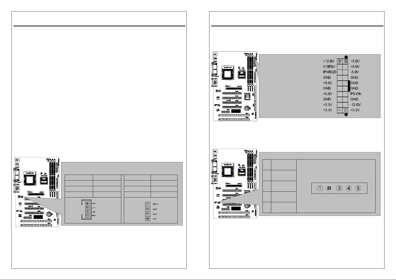
13.CPU/Chassis Fan Connectors(FAN1 and FAN2)
This motherboard provides CPU, Power, and Chassis fan connectors. Orientate
the fan so that the heat sink fins allow airflow to go across the onboard heat sink(s)
instead of the expansion slots. Depending on the fan manufacturer, the wiring and
plug may be different. The red wire should be positive, while the black should be
ground. Connect the fan plug to the board taking into consideration the polarity of
the connector.
Note: The CPU and motherboard will overheat if there is noairflow across the
CPU and onboard heatsink. Damage may occur to the motherboard and the CPU
fan if these pins are incorrectly used. These are not jumpers, do not place jumper
caps over these pins.
System Panel Connectors (J1)
Refer to the following figure for item 14 to 18.
CPU Fan Connectors
CPU Fan Connectors
System Panel Connectors
2-11
2-12
Page 13
3VBAV User’s Manual
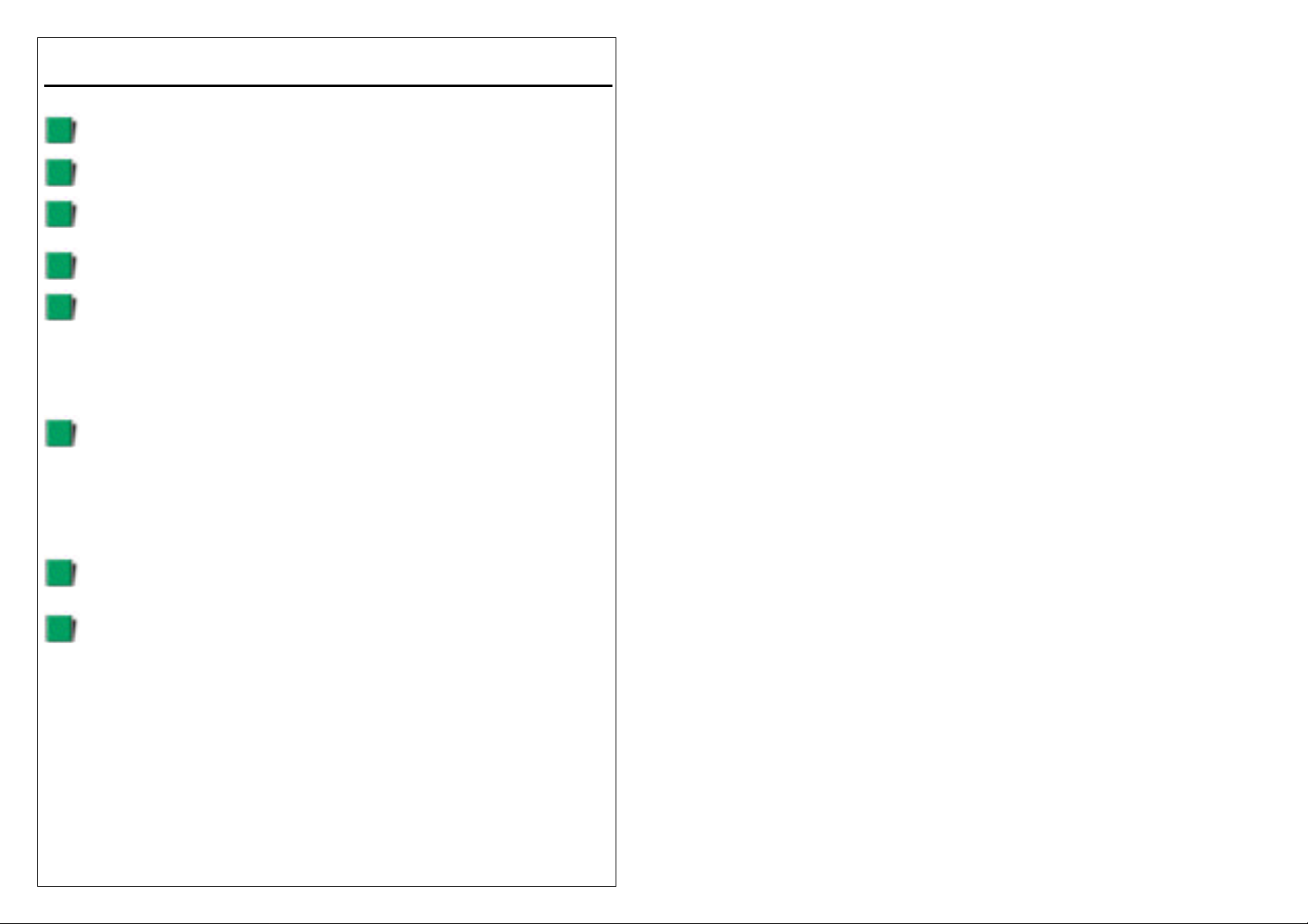
Internal Audio Connectors
IR&CIR Pin Header
14.Power LED Lead
This indicates the status of the system power is turned ”ON’ or ”OFF” The LED will
light when the system power is turned on and will go off when the system power is
turned off.
15.System Warning Speaker Connector
This 4-pin connector connects to the case-mounted speaker.
16.ATX Power Switch Lead
The system power is controlled by a momentary switch connected to this lead.
Pressing the button once will switch the system between ON and SOFT OFF.
Pushing the switch while in the ON mode for more than 4 seconds will turn the
system off. The Power LED shows the status of the system power.
17.HDD LED Lead
This connector supplies power to the cabinet IDE activity LED. Read and write
activity by devices connected to the Primary or Secondary IDE connectors will
cause the LED to Light up.
18.Reset Switch Lead
This 2-pin connector connects to the case-mounted reset switch for rebooting your
computer without having to turn off your power switch. This is a preferred method
of rebooting to extend the life of the system power supply.
19. Internal Audio Connectors:
These connectors allow you to receive stereo audio input from the sound sources
such as CD-ROM, TV tuner, and MPEG card.
CD1 CD2
PIN FUNCTION PIN FUNCTION
1 RIGHT 1 RIGHT
2,4 GND 2,3 GND
3 LEFT 4 LEFT
3VBAV User’s Manual
20.ATX Power Connector:
This connector connects to an ATX power supply. The plug from the power
supply will only insert in one orientation because of the different hole sizes. Find
the proper orientation and push down firmly making sure that the pins are aligned.
21.IR Pin Header:IR1
ATX Power Connector
PIN
1 +5 VCC
3 IRRX
4 GND
5 IRTX
IR1
2-13
2-14
Page 14
3VBAV User’s Manual
2-6 Power Connection Procedures
After all connections are made, close the system case cover.
Be sure that all switches are OFF.
Connect the power supply cord to the power supply located on the back of
your system case according to your system user manual.
Connect the power cord to a power outlet that is equipped with a surge
protector.
You may then turn ON your devices in the following order:
(1) Your monitor
(2) External SCSI devices (starting with the last device on the chain)
(3) Your system power For ATX power supplies, you need to switch ON the
power supply if a switch is provided as well as press the ATX power
switch on the front of the case.
The power LED on the front panel of the system case will light. For ATX
power supplies, the power LED will light when the ATX power switch is
pressed. The system will then run power-On tests. While the tests are
running, additional messages will appear on the screen. If you do not see
anything within 30 seconds from the time you turn on the power, the system
may have failed a power-on test. Check your jumper settings and
connections again or call your retailer for assistance.
During power-ON, hold down <Delete> to enter BIOS setup.
Follow the instructions in chapter 3 BIOS Setup
To power off you computer, you must first exit or shut down your operating
system before switching OFF the power switch. For ATX power supplies,
you can press the ATX power switch after exiting or shutting down your
operating system. If you use Windows 95/98, click the start button,
click shut down, and then click Shut down the computer. The power supply
should turn OFF after Windows shuts down. For ATX power supplies, the
message ”You can now safely turn OFF your computer” will not appear
when shutting down the computer.
2-15
Page 15
3VBAV User’s Manual
AWARD BIOS Setup
3-1 Introduction
This manual discusses Award™ Setup program built into the ROM BIOS. The
Setup program allows users to modify the basic system configuration. This special
information is then stored in battery-backed RAM so that it retains the Setup
information when the power is turned off.
The AwardBIOS™ installed in your computer system’s ROM (Read Only Memory)
is a custom version of an industry standard BIOS. This means that it supports
Intel/Cyrix/AMD processors in a standard IBM-AT compatible input/output system.
The BIOS provides critical low-level support for standard devices such as disk
drives and serial and parallel ports.
The AwardBIOS™ has been customized by adding important, but non-standard,
features such as virus and password protection as well as special support for
detailed fine-tuning of the chipset controlling the entire system.
The rest of this manual is intended to guide you through the process of configuring
your system using Setup.
Starting Setup
The AwardBIOS™ is immediately activated when you first power on the computer.
The BIOS reads the system information contained in the CMOS and begins the
process of checking out the system and configuring it. When it finishes, the BIOS
will seek an operating system on one of the disks and then launch and turn control
over to the operating system.
While the BIOS is in control, the Setup program can be activated in one of two
ways:
1. By pressing <Del> immediately after switching the system on, or
2. By pressing the <Del> key when the following message appears briefly at the
bottom of the screen during the POST (Power On Self-Test).
Press DEL to enter SETUP.
If the message disappears before you respond and you still wish to enter Setup,
restart the system to try again by turning it OFF then ON or pressing the "RESET"
button on the system case. You may also restart by simultaneously pressing
<Ctrl>, <Alt>, and <Delete> keys. If you do not press the keys at the correct time
and the system does not boot, an error message will be displayed and you will
again be asked to...
3-1
3VBAV User’s Manual
PRESS F1 TO CONTINUE, DEL TO ENTER SETUP
Using Setup
In general, you use the arrow keys to highlight items, press <Enter> to select, use
the PageUp and PageDown keys to change entries, press <F1> for help and
press <Esc> to quit. The following table provides more detail about how to
navigate in the Setup program using the keyboard.
Key
Up arrow Move to previous item
Down arrow Move to next item
Left arrow Move to the item in the left hand
Right arrow Move to the item in the right hand
Esc key Main Menu -- Quit and not save changes into CMOS
PgUp key Increase the numeric value or make changes
PgDn key Decrease the numeric value or make changes
+ key Increase the numeric value or make changes
- key Decrease the numeric value or make changes
F1 key General help, only for Status Page Setup Menu and Option
(Shift)F2 key Change color from total 16 colors. F2 to select color
F3 key Calendar, only for Status Page Setup Menu
F4 key Reserved
F5 key Restore the previous CMOS value from CMOS, only for
F6 key Load the default CMOS value from BIOS default table, only
F7 key Load the default
F8 key Reserved
F9 key Reserved
F10 key Save all the CMOS changes, only for Main Menu
Navigating through the menu bar
Use the left and right arrow keys to choose the menu you want to be in.
Function
Status Page Setup Menu and Option Page Setup Menu -- Exit
current page and return to Main Menu
Page Setup Menu
forward, (Shift) F2 to select color backward
Option Page Setup Menu
for Option Page Setup Menu
3-2
Page 16
3VBAV User’s Manual
To display a sub menu
use the arrow keys to move the cursor to the sub menu you want. Then press
<Enter>.
Getting Help
Press F1 to pop up a small help window that describes the appropriate keys to
use and the possible selections for the highlighted item. To exit the Help Window
press <Esc> or the F1 key again.
In Case of Problems
If, after making and saving system changes with Setup, you discover that your
computer no longer is able to boot, the AwardBIOS™ supports an override to the
CMOS settings which resets your system to its defaults.
The best advice is to only alter settings which you thoroughly understand. To this
end, we strongly recommend that you avoid making any changes to the chipset
defaults. These defaults have been carefully chosen by both Award and your
systems manufacturer to provide the absolute maximum performance and
reliability. Even a seemingly small change to the chipset setup has the potential
for causing you to use the override.
A Final Note About Setup
Not all systems have the same Setup. While the basic look and function of the
Setup program remains the same for all systems, individual motherboard and
chipset combinations require custom configurations. For example, you may find
that your Setup main menu has a different number of entries from the main menu
displayed in this manual. These are simply features not supported (or not user
configurable) on your system.
The final appearance of the Setup program also depends on the Original
Equipment Manufacturer (OEM) who built your system. If your OEM has decided
that certain items should only be available to their technicians, those items may
very well be removed from the Setup program.
3VBAV User’s Manual
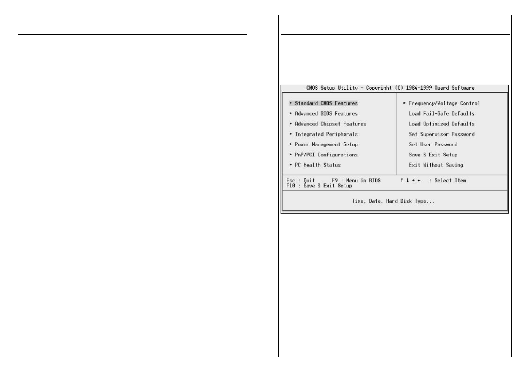
3-2 Main Menu
Once you enter the AwardBIOS™ CMOS Setup Utility, the Main Menu will appear
on the screen. The Main Menu allows you to select from several setup functions
and two exit choices. Use the arrow keys to select among the items and press
<Enter> to accept and enter the sub-menu.
Note that a brief description of each highlighted selection appears at the bottom of
the screen.
Setup Items
The main menu includes the following main setup categories. Recall that some
systems may not include all entries.
Standard CMOS Features
Use this menu for basic system configuration.
Advanced BIOS Features
Use this menu to set the Advanced Features available on your system.
Advanced Chipset Features
Use this menu to change the values in the chipset registers and optimize your
system's performance.
3-3
3-4
Page 17
3VBAV User’s Manual
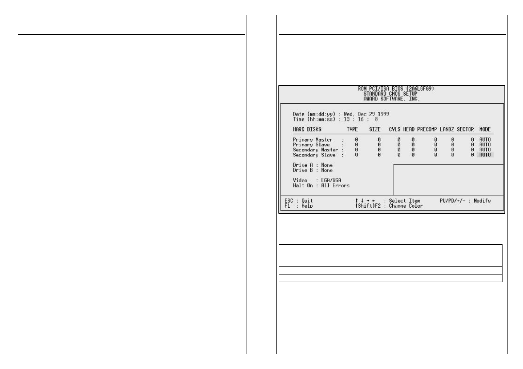
Integrated Peripherals
This section page includes all the items of IDE hard drive and Programmed Input /
Output features.
Power Management Setup
Use this menu to specify your settings for power management.
.
PnP / PCI Configurations
This entry appears if your system supports PNP / PCI.
PC Health Status
This section helps you to get more information about your system including CPU
temperature, FAN speed and voltages.
Frequency/Voltage Control
Use this menu to specify your settings for CPU/DIMM frequency control.
Load Fail-Safe Defaults
Use this menu to load the BIOS default values for the minimal/stable performance
for your system to operate.
Load Optimized Defaults
Use this menu to load the BIOS default values that are factory settings for optimal
performance system operations. While Award has designed the custom BIOS to
maximize performance, the factory has the right to change these defaults to meet
their needs.
Set Supervisor Password
Use this menu to set Supervisor Passwords.
Set User Password
Use this menu to set user Passwords.
Save & Exit Setup
Save CMOS value changes to CMOS and exit setup.
Exit Without Saving
Abandon all CMOS value changes and exit setup.
3VBAV User’s Manual
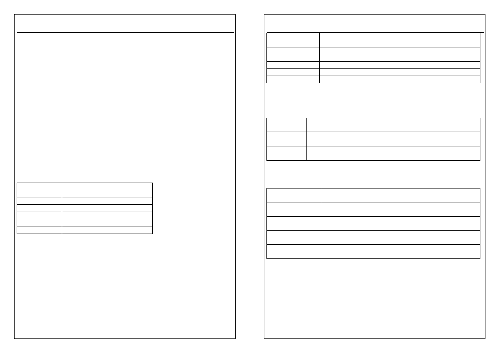
3-3 Standard CMOS Features
The items in Standard CMOS Setup Menu are divided into 10 categories. Each
category includes no, one or more than one setup items. Use the arrow keys to
highlight the item and then use the <PgUp> or <PgDn> keys to select the value
you want in each item.
Date
The date format is <day>, <date> <month> <year>. Press <F3> to show the
calendar.
day The day, from Sun to Sat, determined by the BIOS and is
display-only
date The date, from 1 to 31 (or the maximum allowed in the month)
month The month, Jan through Dec.
year The year, from 1900 through 2099
Time
The time format is <hour> <minute> <second>. The time is calculated based on
the 24-hour military-time clock. For example, 1 p.m. is 13:00:00.
3-5
3-6
Page 18
3VBAV User’s Manual
Primary Master/Primary Slave/Secondary Master/Secondary Slave
The categories identify the types of 2 channels that have been installed in the
computer. There are 45 predefined types and 4 user definable types are for
Enhanced IDE BIOS. Type 1 to Type 45 are predefined. Type user is
user-definable.
Press PgUp or PgDn to select a numbered hard disk type or type the number and
press <Enter>. Note that the specifications of your drive must match with the drive
table. The hard disk will not work properly if you enter improper information for this
category. If your hard disk drive type is not matched or listed, you can use Type
“User” to define your own drive type manually.
If you select Type “User”, you will need to know the information listed below.
Enter the information directly from the keyboard and press <Enter>. This
information should be included in the documentation from your hard disk vendor
or the system manufacturer.
If the controller of HDD interface is ESDI, the selection shall be “Type 1”.
If the controller of HDD interface is SCSI, the selection shall be “None”.
If you select Type ”Auto”, BIOS will Auto-Detect the HDD & CD-ROM Drive at the
POST stage and showing the IDE for HDD & CD-ROM Drive.
TYPE drive type
CYLS. number of cylinders
HEADS number of heads
PRECOMP write precom
LANDZONE landing zone
SECTORS number of sectors
MODE mode type
If a hard disk has not been installed select NONE and press <Enter>.
Drive A Type / Drive B Type
The category identifies the types of floppy disk drive A or drive B that have been
installed in the computer.
3-7
3VBAV User’s Manual
None No floppy drive installed
360K, 5.25 in 5-1/4 inch PC-type standard drive; 360 kilobyte capacity
1.2M, 5.25 in 5-1/4 inch AT-type high-density drive; 1.2 megabyte
capacity
720K, 3.5 in 3-1/2 inch double-sided drive; 720 kilobyte capacity
1.44M, 3.5 in 3-1/2 inch double-sided drive; 1.44 megabyte capacity
2.88M, 3.5 in 3-1/2 inch double-sided drive; 2.88 megabyte capacity
Video
The category selects the type of video adapter used for the primary system
monitor. Although secondary monitors are supported, you do not have to select
the type in Setup.
EGA/VGA Enhanced Graphics Adapter/Video Graphics Array. For EGA,
VGA, SEGA, SVGA or PGA monitor adapters.
CGA 40 Color Graphics Adapter, power up in 40 column mode
CGA 80 Color Graphics Adapter, power up in 80 column mode
MONO Monochrome adapter, includes high resolution monochrome
adapters
Halt On
The category determines whether the computer will stop if an error is detected
during power up.
No errors The system boot will not be stopped for any error that
may be detected.
All errors Whenever the BIOS detects a non-fatal error the system
will be stopped and you will be prompted.
All,
But Keyboard
All, But Diskette The system boot will not stop for a disk error; it will stop
All, But Disk/Key The system boot will not stop for a keyboard or disk error;
Memory
The category is display-only which is determined by POST (Power On Self Test)
of the BIOS.
Base Memory
The POST will determine the amount of base (or conventional) memory installed
in the system. The value of the base memory is typically 512K for systems with
The system boot will not stop for a keyboard error; it will
stop for all other errors.
for all other errors.
it will stop for all other errors.
3-8
Page 19
3VBAV User’s Manual
512K memory installed on the motherboard, or 640K for systems with 640K or
more memory installed on the motherboard.
Extended Memory
The BIOS determines how much extended memory is present during the POST.
This is the amount of memory located above 1MB in the CPU's memory address
map.
Other Memory
This refers to the memory located in the 640K to 1024K address space. This is
memory that can be used for different applications. DOS uses this area to load
device drivers in an effort to keep as much base memory free for application
programs. The BIOS is the most frequent user of this RAM area since this is
where it shadows RAM
3VBAV User’s Manual
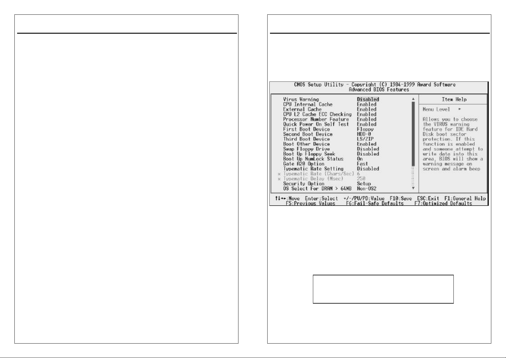
3-4 Advanced BIOS Features
This section allows you to configure your system for basic operation. You have the
opportunity to select the system’s default speed, boot -up sequence, keyboard
operation, shadowing and security.
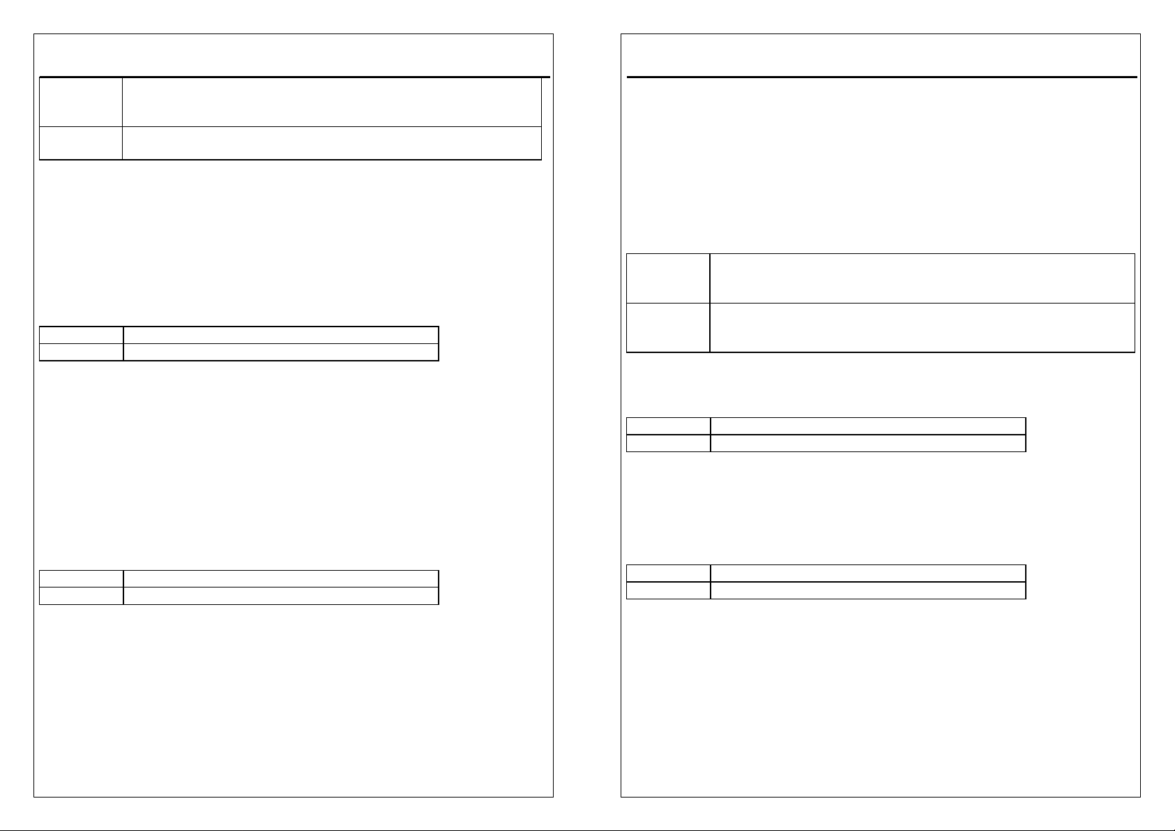
Virus Warning
When this item is enabled, the Award BIOS will monitor the boot sector and
partition table of the hard disk drive for any attempt at modification. If an attempt is
made, the BIOS will halt the system and the following error message will appear.
Afterwards, if necessary, you will be able to run an anti-virus program to locate
and remove the problem before any damage is done.
! WARNING !
Disk boot sector is to be modified
3-9
Type "Y" to accept write or "N" to abort write
Award Software, Inc.
3-10
Page 20
3VBAV User’s Manual
Enabled Activates automatically when the system boots up causing a
warning message to appear when anything attempts to access
the boot sector or hard disk partition table.
Disabled No warning message will appear when anything attempts to
access the boot sector or hard disk partition table.
NOTE: Many disk diagnostic programs which attempt to access the
boot sector table can cause the above warning message. If
you will be running such a program, we recommend that you
first disable Virus Protection beforehand.
CPU Internal Cache/External Cache
These two categories speed up memory access. However, it depends on
CPU/chipset design. The default value is en able.
Enabled Enable cache
Disabled Disable cache
CPU L2 Cache ECC Checking
This item allows you to Enable/Disable CPU L2 Cache ECC checking.
The Choice: Enabled, Disabled.
Processor Number Feature
The item is used to Enabled/Disabled the Processor Number Feature.
The Choice: Enabled, Disabled.
Quick Power On Self Test
This category speeds up Power On Self Test (POST) after you power up the
computer. If it is set to Enable, BIOS will shorten or skip some check items during
POST.
Enabled Enable quick POST
Disabled Normal POST
First/Second/Third Boot Device
The BIOS attempts to load the operating system from the devices in the sequence
selected in these items.
The Choice: Floppy, LS/ZIP, HDD, SCSI, CDROM, LAN.
3-11
3VBAV User’s Manual
Boot Other Device
This item allows you can boot by other device.
The Choice: Enabled, Disabled.
Swap Floppy Drive
This item allows you to determine whether enable the swap floppy drive or not.
The Choice: Enabled, Disabled.
Boot Up Floppy Seek
During POST, BIOS will determine if the floppy disk drive installed is 40 or 80
tracks. 360K type is 40 tracks while 760K, 1.2M and 1.44M are all 80 tracks.
Enabled BIOS searches for floppy disk drive to determine if it is 40 or 80
tracks. Note that BIOS can not tell from 720K, 1.2M or 1.44M drive
type as they are all 80 tracks.
Disabled BIOS will not search for the type of floppy disk drive by track
number. Note that there will not be any warning message if the
drive installed is 360K.
Boot Up NumLock Status
This allows you to determine the default state of the numeric keypad. By default,
the system boots up with NumLock on.
On Keypad is number keys
Off Keypad is arrow keys
Gate A20 Option
This entry allows you to select how the gate A20 is handled. The gate A20 is a
device used to address memory above 1 Mbytes. Initially, the gate A20 was
handled via a pin on the keyboard. Today, while keyboards still provide this
support, it is more common, and much faster, for the system chipset to provide
support for gate A20.
Normal keyboard
Fast chipset
Typematic Rate Setting
This determines if the typematic rate is to be used. When disabled, continually
holding down a key on your keyboard will generate only one instance. In other
words, the BIOS will only report that the key is down. When the typematic rate is
enabled, the BIOS will report as before, but it will then wait a moment, and, if the
key is still down, it will begin the report that the key has been depressed
repeatedly. For example, you would use such a feature to accelerate cursor
movements with the arrow keys.
3-12
Page 21
3VBAV User’s Manual
Enabled Enable typematic rate
Disabled Disable typematic rate
Typematic Rate(Chars/Sec)
When the typematic rate is enabled, this selection allows you select the rate at
which the keys are accelerated.
6 6 characters per second
8 8 characters per second
10 10 characters per second
12 12 characters per second
15 15 characters per second
20 20 characters per second
24 24 characters per second
30 30 characters per second
Typematic Delay (Msec)
When the typematic rate is enabled, this selection allows you to select the delay
between when the key was first depressed and when the acceleration begins.
250 250 msec
500 500 msec
750 750 msec
1000 1000 msec
Security Option
This category allows you to limit access to the system and Setup, or just to Setup.
System The system will not boot and access to Setup will be denied if the
correct password is not entered at the prompt.
Setup The system will boot, but access to Setup will be denied if the
correct password is not entered at the prompt.
Note: To disable security, select PASSWORD SETTING at Main Menu and then
you will be asked to enter password. Do not type anything and just press <Enter>,
it will disable security. Once the security is disabled, the system will boot and you
can enter Setup freely.
OS Select for DRAM > 64MB
This item allows you to access the memory that over 64MB in OS/2.
The Choice: Non-OS2, OS2.
3-13
3VBAV User’s Manual
Video BIOS Shadow
Determines whether video BIOS will be copied to RAM. However, it is optional
depending on chipset design. Video Shadow will increase the video speed.
Enabled Video shadow is enabled
Disabled Video shadow is disabled
C8000 - CBFFF Shadow/DC000 - DFFFF Shadow
These categories determine whether option ROMs will be copied to RAM. An
example of such option ROM would be support of on-board SCSI.
Enabled Optional shadow is enabled
Disabled Optional shadow is disabled
3-14
Page 22
3VBAV User’s Manual
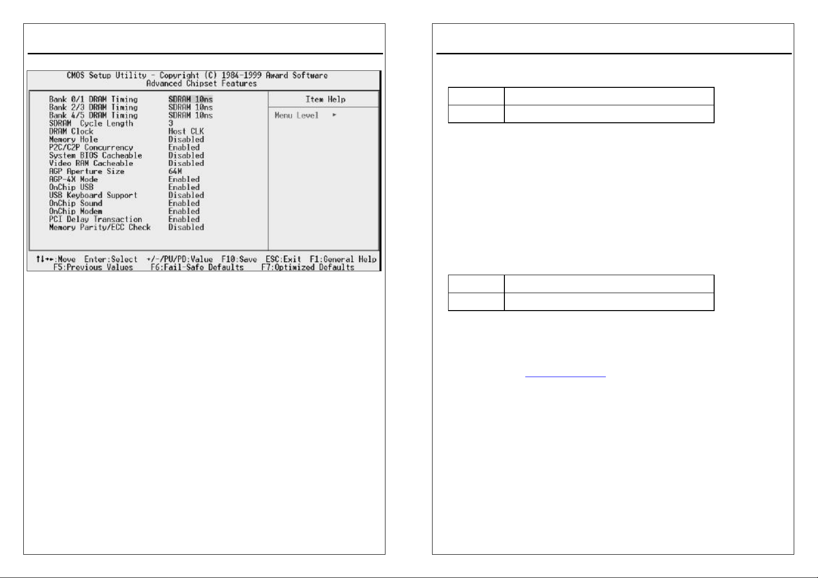
3-5 Advanced Chipset Features
The parameters in this screen are for system designers, service personnel, and
technically competent users only. Do not reset these values unless you
understand the consequences of your changes.
NOTE: This chapter describes all fields offered by Award Software in this screen.
Your system board designer may omit or modify some fields.
Bank 0/1, 2/3, 4/5 DRAM Timing
The DRAM timing of Bank 0/1, 2/3, 4/5, 6/7 in this field is set by the system board
manufacturer, depending on whether the board has fast paged DRAMs or EDO
(extended data output) DRAMs.
The Choice: SDRAM 10ns,SDRAM 8ns,Normal, Medium, Fast, Turbo.
SDRAM Cycle Length
This field sets the CAS latency timing.
The Choice: 2, 3.
DRAM Clock
This item allows you select DRAM clock.
The Choice: Host CLK,HCLK-33M,HCLK+33M.
3-15
3VBAV User’s Manual
Memory Hole
In order to improve performance, certain space in memory can be reserved for
ISA cards. This memory must be mapped into the memory space below 16 MB.
15M-16M Memory hole supported.
Disabled Memory hole not supported.
P2C/C2P Concurrency.
When disable, CPU bus will be occupied during the entire PCI operation period.
The Choice: Enabled, Disabled.
System BIOS Cacheable
This item allows you enable/disable system BIOS cacheable.
The Choice: Enabled, Disabled.
Video RAM Cacheable
Select Enabled allows caching of the video RAM , resulting in better system
performance. However, if any program writes to this memory area, a system
error may result.
Enabled Video RAM access cached
Disabled Video RAM access not cached
AGP Aperture Size
Select the size of the Accelerated Graphics Port (AGP) aperture. The aperture is a
portion of the PCI memory address range dedicated for graphics memory address
space. Host cycles that hit the aperture range are forwarded to the AGP without
any translation. See www.agpforum.org for AGP information.
The Choice: 4M, 8M, 16M, 32M, 64M, 128M.
AGP-4X Mode
This item allows you select AGP speed.
The Choice: Enabled, Disabled.
OnChip USB
This should be enabled if your system has a USB installed on the system board
and you wish to use it. Even when so equipped, if you add a higher performance
controller, you will need to disable this feature.
The Choice: Enabled, Disabled.
3-16
Page 23
3VBAV User’s Manual
USB Keyboard Support
Select Enabled if your system contains a Universal Serial Bus (USB) controller
and you have a USB keyboard.
The Choice: Enabled, Disabled.
OnChip Sound
This item allow you to Enable/Disable onchip AC97 sound.
The Choice: Enabled, Disabled.
OnChip Modem
This item allow you to Enable/Disable onchip modem.
The Choice: Enabled, Disabled.
PCI Delay Transaction
The chipset has an embedded 32-bit posted write buffer to support delay
transactions cycles. Select Enabled to support compliance with PCI specification
version 2.1.
The Choice: Enabled, Disabled.
Memory Parity/ECC Check
This item allows you to Enable/Disable Memory Parity/ECC check.
The Choice: Enabled/Disabled.
3-17
3VBAV User’s Manual
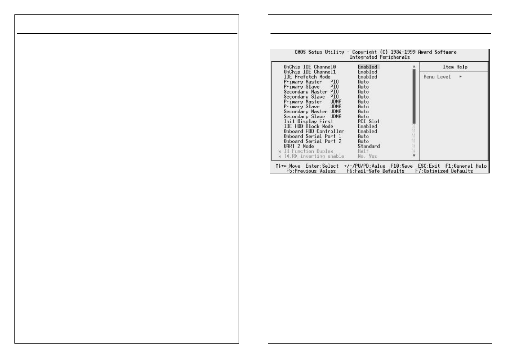
3-6 Intergrated Peripherals
OnChip IDE Channel0/ Channel1
The chipset contains a PCI IDE interface with support for two IDE channels.
Select Enabled to activate the first and/or second IDE interface. Select Disabled to
deactivate an interface, if you install a primary and/or secondary add-in IDE
interface.
The Choice: Enabled, Disabled.
IDE Prefetch Mode
The onboard IDE drive interfaces supports IDE prefetching for faster drive
accesses. If you install a primary and/or secondary add-in IDE interface, set this
field to Disabled if the interface does not support prefetching.
The Choice: Enabled, Disabled.
IDE Primary/Secondary Master/Slave PIO
The four IDE PIO (Programmed Input/Output) fields let you set a PIO mode (0-4)
for each of the four IDE devices that the onboard IDE interface supports. Modes 0
through 4 provide successively increased performance. In Auto mode, the system
automatically determines the best mode for each device.
The Choice: AUTO, Mode 0-Mode 4.
3-18
Page 24

3VBAV User’s Manual
IDE Primary/Secondary Master/Slave UDMA
Ultra DMA/33 implementation is possible only if your IDE hard drive supports it
and the operating environment includes a DMA driver (Windows 95 OSR2 or a
third-party IDE bus master driver). If your hard drive and your system software
both support Ultra DMA/33, select Auto to enable BIOS support.
The Choice: Auto, Disabled
Init Display First
This item allows you to decide to active PCI Slot or AGP first
The Choice: PCI Slot, AGP.
IDE HDD Block Mode
Block mode is also called block transfer, multiple commands, or multiple sector
read/write. If your IDE hard drive supports block mode (most new drives do),
select Enabled for automatic detection of the optimal number of block read/writes
per sector the drive can support.
The Choice: Enabled, Disabled.
Onboard FDD Controller
This should be enabled if your system has a floppy disk drive (FDD) installed on
the system board and you wish to use it. Even when so equipped, if you add a
higher performance controller, you will need to disable this feature.
The Choice: Enabled, Disabled.
Onboard Serial Port 1/Port 2
This item allows you to determine access onboard serial port 1/port 2 controller
with which I/O address.
The Choice: 3F8/IRQ4, 2F8/IRQ3, 3E8/IRQ4, 2E8/IRQ3, Disabled, Auto.
UART 2 Mode
This item allows you to determine which Infra Red (IR) function of onboard I/O
chip.
The Choice: Standard, ASKIR, HPSIR.
Onboard Parallel Port
Select a logical LPT port name and matching address for the physical parallel
(printer) port.
The Choice: 378/IRQ7, 278/IRQ5, 3BC/IRQ7, Disabled.
3VBAV User’s Manual
Onboard Parallel Mode
Select an operating mode for the onboard parallel (printer) port. Normal EPP
(Extended Parallel Port) ECP (Extended Capabilities Port) CEP+EPP PC AT
parallel port Bidirectional port Fast, buffered port Fast, buffered, bidirectional port.
Select Normal unless you are certain your hardware and software both support
EPP or ECP mode.
The Choice : Normal, EPP, ECP, ECP/EPP.
ECP Mode Use DMA
Select a DMA channel for the port.
The Choice : 3, 1.
Parallel Port EPP Type
Select EPP port type 1.7 or 1.9.
The Choice : EPP1.7, EPP1.9
3-19
3-20
Page 25
3VBAV User’s Manual
3-7 Power Management Setup
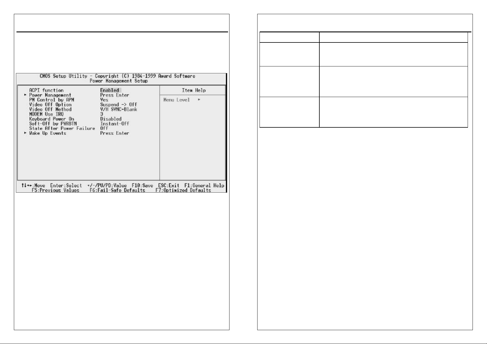
The Power Management Setup allows you to configure you system to most
effectively save energy while operating in a manner consistent with your own style
of computer use.
ACPI function
This item allows you to enable/disable the Advanced Configuration and Power
Management (ACPI).
The Choice: Enabled, Disabled.
Power Management
This category allows you to select the type (or degree) of power saving and is
directly related to the following modes:
1. HDD Power Down
2. Doze Mode
3. Suspend Mode
There are three selections for Power Management, three of which have fixed
mode settings.
3VBAV User’s Manual
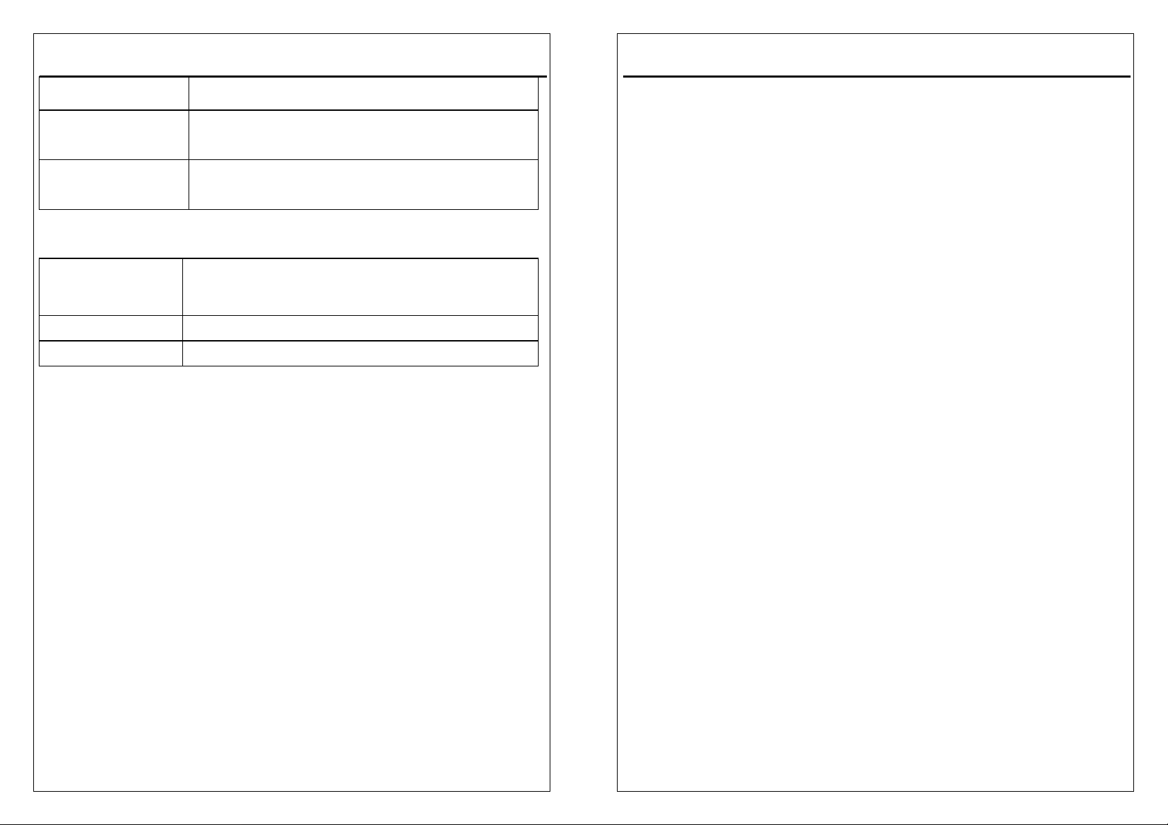
Disable (default) No power management. Disables all four modes
Min. Power Saving
Max. Power Saving Maximum power management -- ONLY AVAILABLE
User Defined
HDD Power Down
When enabled and after the set time of system inactivity, the hard disk drive will
be powered down while all other devices remain active.
The Choice:Disable,1-15Min.
Minimum power management. Doze Mode = 1 hr.
Standby Mode = 1 hr., Suspend Mode = 1 hr., and HDD
Power Down = 15 min.
FOR SL CPU’S. Doze Mode = 1 min., Standby Mode =
1 min., Suspend Mode = 1 min., and HDD Power Down
= 1 min.
Allows you to set each mode individually. When not
disabled, each of the ranges are from 1 min. to 1 hr.
except for HDD Power Down which ranges from 1 min.
to 15 min. and disable.
Doze Mode
When enabled and after the set time of system inactivity, the CPU clock will run at
slower speed while all other devices still operate at full speed.
The Choice: Disable, 1Min-1Hour.
Suspend Mode
When enabled and after the set time of system inactivity, all devices except the
CPU will be shut off.
The Choice: Disable, 1Min-1Hour.
PM Control by APM
When enabled, an Advanced Power Management device will be activated to
enhance the Max. Power Saving mode and stop the CPU internal clock.
If the Max. Power Saving is not enabled, this will be preset to No.
The Choice: Yes, No.
Video Off Option
When enabled, this feature allows the VGA adapter to operate in a power saving
mode.
3-21
3-22
Page 26
3VBAV User’s Manual
Always On Monitor will remain on during power saving modes.
Suspend --> Off Monitor blanked when the systems enters the
Suspend mode.
All Modes --> Off Monitor blanked when the system enters any power
saving mode.
Video Off Method
This determines the manner in which the monitor is blanked.
V/H SYNC+Blank
Blank Screen This option only writes blanks to the video buffer.
DPMS Support Initial display power management signaling.
This selection will cause the system to turn off the
vertical and horizontal synchronization ports and write
blanks to the video buffer.
MODEM Use IRQ
This determines the IRQ in which the MODEM can use.
The Choice: 3, 4, 5, 7, 9, 10, 11, NA.
Keyboard Power On
If enable this item, you can boot up the system by power button and the wake-up
Key on Keyboard 98 .
The Choice: Enabled, Disabled.
Soft-Off by PWRBTN
When Enabled, turning the system off with the on/off button places the system in a
very low-power-usage state, with only enough circuitry receiving power to detect
power button activity or Resume by Ring activity.
The Choice: Instant-Off, Delay 4 Sec.
State After Power Failure
A traditional ATX system should remain at power off stage when AC power
resumes from power failure. This design is inconvenient for a network server or
workstation, without an UPS, that needs to keep power-on. This item is used to
solve this problem. Selecting On lets the system can automatically power-on after
AC power resumes; in the other hand, the system will power-off if you select Off. If
Auto option is selected, the system will power-on or power-off based on the
3-23
3VBAV User’s Manual
original state.
The Choice: Off, On, Auto.
Wake Up Events:
VGA
When set to On (default), any event occurring at a VGA port will awaken a system
which has been powered down.
The Choice: ON,OFF.
LPT & COM
When set to LPT/COM(default), any event occurring at a COM(serial)/LPT (printer)
port will awaken a system which has been powered down.
The Choice: LPT/COM,NONE,LPT,COM.
HDD & FDD
When set to On (default), any event occurring at a hard or floppy drive port will
awaken a system which has been powered down.
The Choice: ON,OFF.
PCI Master
When set to On (default), any event occurring at will awaken a system which has
been powered down.
The Choice: ON,OFF.
GPI Resume
This item allow you to Enable/Disable GPI Resume.
The Choice: Enabled, Disabled.
Modem Ring Resume
When set to Enabled, any event occurring to the Modem Ring will awaken a
system which has been powered down.
The Choice: Enabled, Disabled.
RTC Alarm Resume
When Enabled, your can set the date and time at which the RTC (real-time clock)
alarm awakens the system from Suspend mode
The Choice: Enabled, Disabled.
Primary INTR
When set to On (default), any event occurring at will awaken a system which has
been powered down.
3-24
Page 27
3VBAV User’s Manual
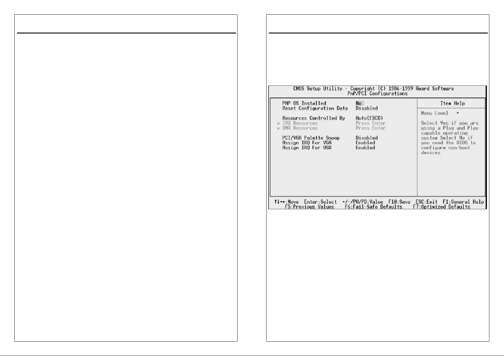
The Choice: ON,OFF.
The following is a list of IRQ’s, Interrupt ReQuests, which can be exempted much
as the COM ports and LPT ports above can. When an I/O device wants to gain
the attention of the operating system, it signals this by causing an IRQ to occur.
When the operating system is ready to respond to the request, it interrupts itself
and performs the service.
As above, the choices are On and Off. Off is the default.
When set On, activity will neither prevent the system from going into a power
management mode nor awaken it.
IRQ3 (COM 2 )
IRQ4 (COM 1)
IRQ5 (LPT 2)
IRQ6 (Floppy Disk)
IRQ7 (LPT 1)
IRQ8 (RTC Alarm)
IRQ9 (IRQ2 Redir)
IRQ10 (Reserved)
IRQ11 (Reserved)
IRQ12 ( PS / 2 Mouse )
IRQ13 (Coprocessor)
IRQ14 (Reserved)
IRQ15 (Reserved)
3-25
3VBAV User’s Manual
3-8 PnP/PCI Configuration
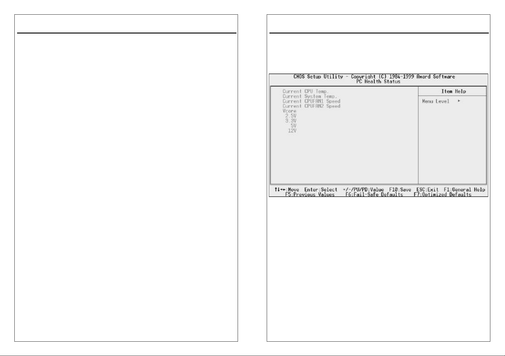
This section describes configuring the PCI bus system. PCI, or Personal
Computer Interconnect, is a system which allows I/O devices to operate at speeds
nearing the speed the CPU itself uses when communicating with its own special
components. This section covers some very technical items and it is strongly
recommended that only experienced users should make any changes to the
default settings.
PNP OS Installed
Select Yes if the system operating environment is Plug-and-Play aware (e.g.,
Windows 95).
The Choice: Yes , No.
Reset Configuration Data
Normally, you leave this field Disabled. Select Enabled to reset Extended System
Configuration Data (ESCD) when you exit Setup if you have installed a new
add-on and the system reconfiguration has caused such a serious conflict that the
operating system cannot boot.
The Choice: Enabled and Disabled.
Resource Controlled By
The Award Plug and Play BIOS can automatically configure all the boot and Plug
3-26
Page 28
3VBAV User’s Manual
and Play-compatible devices. If you select Auto, all the interrupt request (IRQ) and
DMA assignment fields disappear, as the BIOS automatically assigns them.
The Choice: Auto and Manual.
IRQ Resources
When resources are controlled manually, assign each system interrupt as one of
the following types, depending on the type of device using the interrupt:
Legacy ISA Devices compliant with the original PC AT bus specification, requiring
a specific interrupt (such as IRQ4 for serial port 1).
PCI/ISA PnP Devices compliant with the Plug and Play standard, whether
designed for PCI or ISA bus architecture.
DMA Resources
When resources are controlled manually, assign each system DMA channel as
one of the following types, depending on the type of device using the interrupt:
Legacy ISA Devices compliant with the original PC AT bus specification, requiring
a specific DMA channel PCI/ISA PnP Devices compliant with the Plug and Play
standard, whether designed for PCI or ISA bus architecture.
PCI/VGA Palette Snoop
Leave this field at Disabled.
The Choices: Enabled, Disabled.
PCI Delay Transaction
The chipset has an embedded 32-bit posted write buffer to support delay
transactions cycles. Select Enabled to support compliance with PCI specification
version 2.1.
The Choice: Enabled, Disabled.
Assign IRQ For VGA/USB
Name the interrupt request (IRQ) line assigned to the VGA/USB (if any) on your
system. Activity of the selected IRQ always awakens the system.
The Choice: Enabled, Disabled.
3-27
3VBAV User’s Manual
3-9 PC Health States
This section helps you to get more information about your system including
CPU temperature, FAN speed and voltages. It is recommended that you contact
with your motherboard supplier to get proper value about your setting of the CPU
temperature.
Current CPU Temp
Show you the current CPU temperature.
Current System Temp
Show you the current system temperature.
Current CPUFAN1 Speed
Show you the current CPUFAN 1 speed.
Current CPUFAN2 Speed
Show you the current CPUFAN 1 speed.
Vcore
Show you the current system voltage.
3-28
Page 29
3VBAV User’s Manual
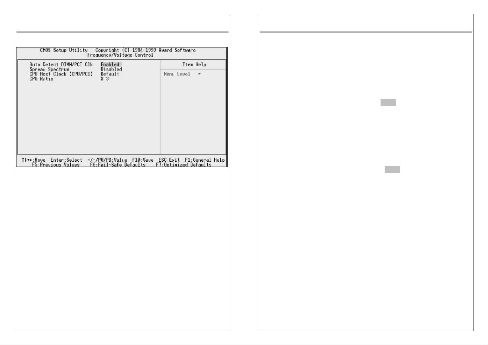
3-10 Frequency /Voltage Control
Auto Detect DIMM/PCI Clk
This item allow you to Enable/Disable system auto detect DIMM/PCI clock.
The Choice: Enabled, Disabled.
Spread Spectrum
This item allows you to enable/disable the spread spectrum modulate.
The Choice: Enabled, Disabled.
CPU Host Clock (CPU/PCI)
This item allows you to select the CPU and PCI Frequency.
The Choice:Default,66/33MHz,75/37MHz,83/41MHz,100/33MHz,103/34MHz,
112/37MHz,124/41MHz,133/44MHz,124/31MHz,133/33MHz,
140/35MHz,150/37MHz.
CPU Ratio
This item allows you to select The CPU ratio.
The Choice:3, 3.5, 4, 4.5, 5, 5.5, 6, 6.5, 7, 7.5, 8.
3-29
3VBAV User’s Manual
3-11 Defaults Menu
Selecting “Defaults” from the main menu shows you two options which are
described below
Load Fail-Safe Defaults
When you press <Enter> on this item you get a confirmation dialog box with a
message similar to:
Load Fail-Safe Defaults (Y/N) ? N
Pressing ‘Y’ loads the BIOS default values for the most stable,
minimal-performance system operations.
Load Optimized Defaults
When you press <Enter> on this item you get a confirmation dialog box with a
message similar to:
Load Optimized Defaults (Y/N) ? N
Pressing ‘Y’ loads the default values that are factory settings for optimal
performance system operations.
3-30
Page 30

3VBAV User’s Manual
3-12 PASSWORD SETTING
You can set either supervisor or user password, or both of then. The differences
between are:
supervisor password : can enter and change the options of the setup menus.
user password : just can only enter but do not have the right to change
the options of the setup menus. When you select this
function, the following message will appear at the center
of the screen to assist you in creating a password.
ENTER PASSWORD:
Type the password, up to eight characters in length, and press <Enter>. The
password typed now will clear any previously entered password from CMOS
memory. You will be asked to confirm the password. Type the password again and
press <Enter>. You may also press <Esc> to abort the selection and not enter a
password.
To disable a password, just press <Enter> when you are prompted to enter the
password. A message will confirm the password will be disabled. Once the
password is disabled, the system will boot and you can enter Setup freely.
PASSWORD DISABLED.
When a password has been enabled, you will be prompted to enter it every time
you try to enter Setup. This prevents an unauthorized person from changing any
part of your system configuration.
Additionally, when a password is enabled, you can also require the BIOS to
request a password every time your system is rebooted. This would prevent
unauthorized use of your computer.
You determine when the password is required within the BIOS Features Setup
Menu and its Security option (see Section 3). If the Security option is set to
“System”, the password will be required both at boot and at entry to Setup. If set
to “Setup”, prompting only occurs when trying to enter Setup.
3VBAV User’s Manual
3-13 Exit Selecting
SAVE & EXIT SETUP
Pressing <Enter> on this item asks for confirmation:
SAVE to CMOS and EXIT (Y/N)? Y
Pressing “Y” stores the selections made in the menus in CMOS – a special
section of memory that stays on after you turn your system off. The next time you
boot your computer, the BIOS configures your system according to the Setup
selections stored in CMOS. After saving the values the system is restarted again.
EXIT WITHOUT SAVING
Pressing <Enter> on this item asks for confirmation:
Quit without saving (Y/N)? Y
This allows you to exit Setup without storing in CMOS any change. The previous
selections remain in effect. This exits the Setup utility and restarts your computer.
3-31
3-32
Page 31
3VBAV User’s Manual
Software Driver Install
4-1 UPDATED PRODUCT INFORMATION
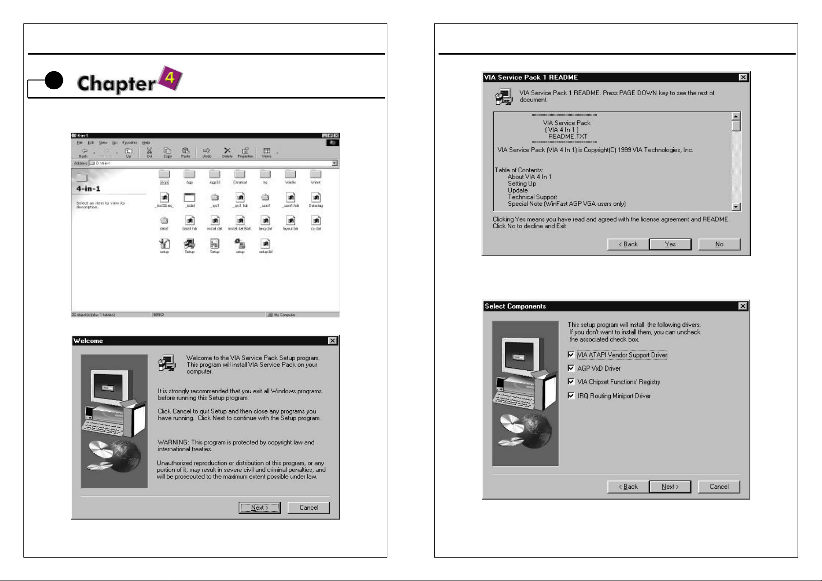
1.Enter the 4IN1 subdirectory and double-click SETUP.EXE.
2.Click "Next" at the Welcome screen.
4-1
3VBAV User’s Manual
3.Read the license agreement and click "Yes" to continue.
4.Select all driver to install and click “NEXT” to continue
4-2
Page 32
3VBAV User’s Manual
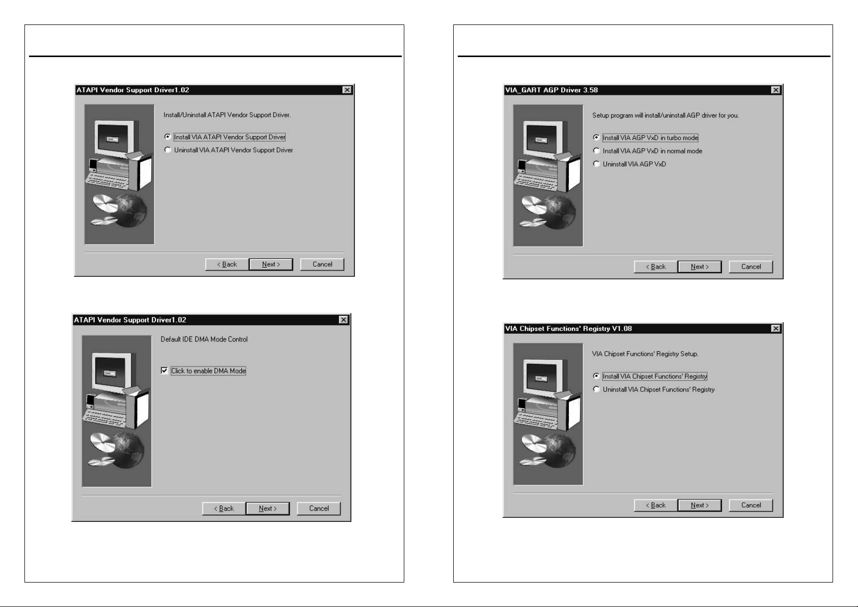
5.Select “Install VIA ATAPI Vendor Support Driver” and click “NEXT” to continue.
6.Select “Click to enable DMA Mode” and click “NEXT” to continue.
4-3
3VBAV User’s Manual
7.Select “Install VIA AGP VxD in turbo mode” and click “NEXT” to continue.
8.Select “Install VIA Chipset Functions’Registry” and click “NEXT” to continue.
4-4
Page 33
3VBAV User’s Manual
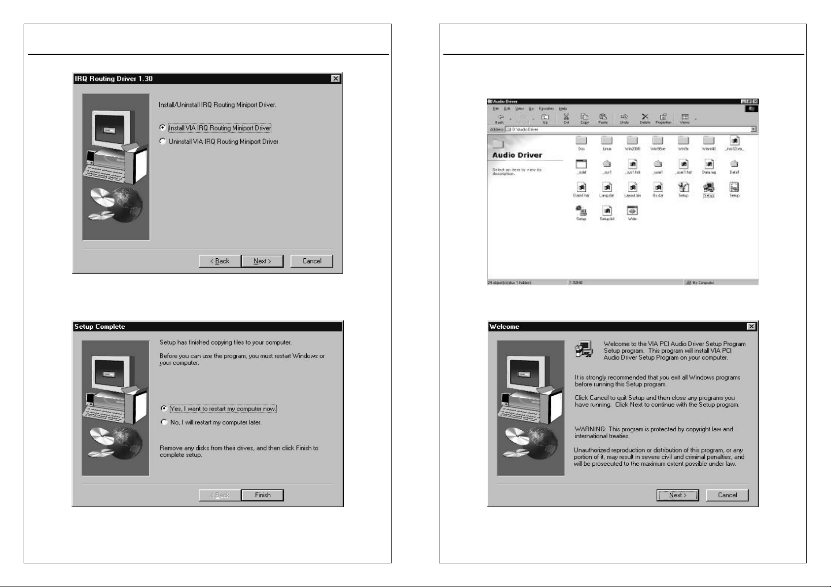
9.Select “Install VIA IRQ Routing Miniport Driver” and click “NEXT” to continue.
10.The driver files will now be installed. When finished installing, choose the "Yes"
to reboot option and click "Finish" to restart your computer. The driver should
now be loaded.
3VBAV User’s Manual
4-2 Install Audio Driver
1.To install with the lates Driver /application, please run SETUP.EXE file (inlcuded
in the “Audio Driver “ subdirectory), double-click SETUP.EXE.
2. Click "Next" at the Welcome screen.
4-5
4-6
Page 34
3VBAV User’s Manual
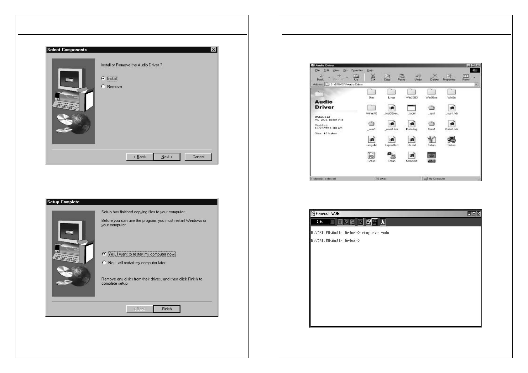
3.Select “install” and click ”NEXT” to continue.
4.Choose the "Yes" to reboot option and click "Finish" to restart your computer.
The driver should now be loaded.
4-7
3VBAV User’s Manual
4-3 Install Audio Driver(WDM)
1.To install with the lates Driver /application, please run WDM.EXE file (inlcuded in
the “Audio Driver “ subdirectory), double-click WDM.EXE.
2.This windows will show on the monitor.
4-8
Page 35
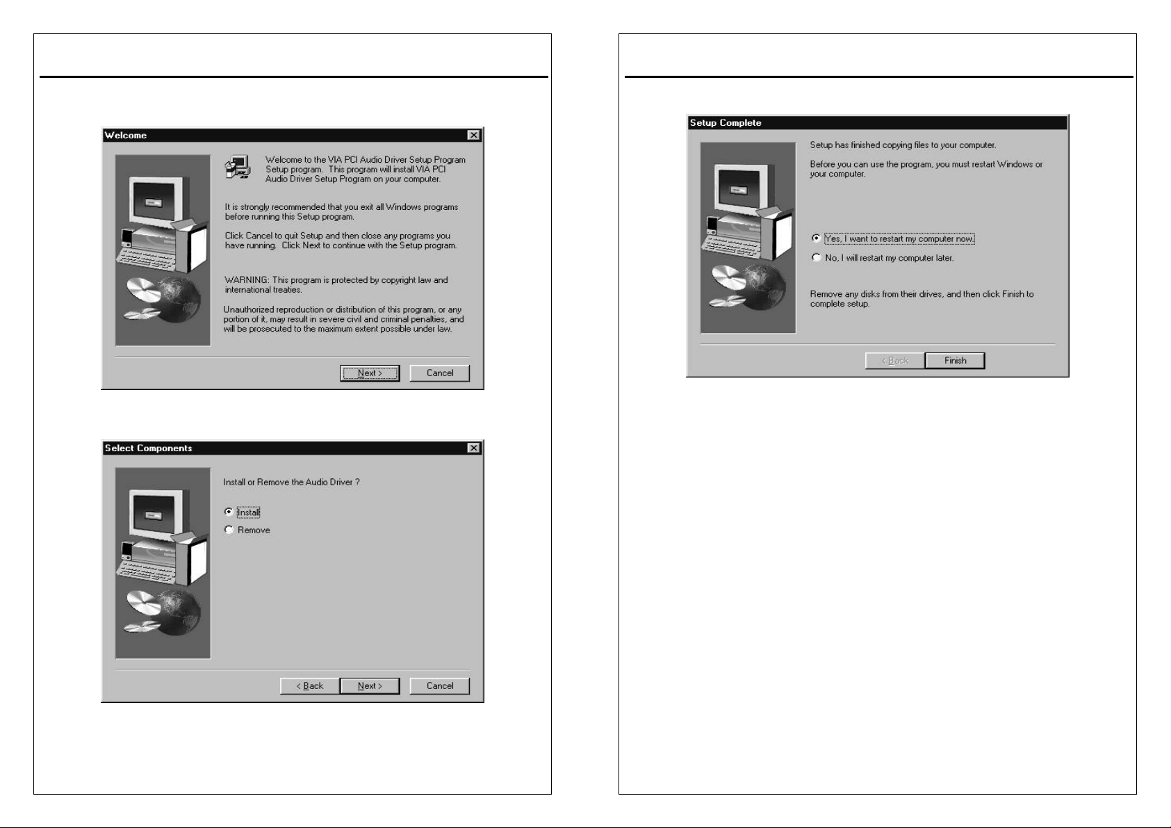
3. Click "Next" at the Welcome screen.
4.Select “install” and click ”NEXT” to continue.
4-9
3VBAV User’s Manual
3VBAV User’s Manual
5.Choose the "Yes" to reboot option and click "Finish" to restart your computer.
The driver should now be loaded.
4-10
Page 36
3VBAV User’s Manual
5
Anti-Virus software installation
5-1 Anti-Virus software installation
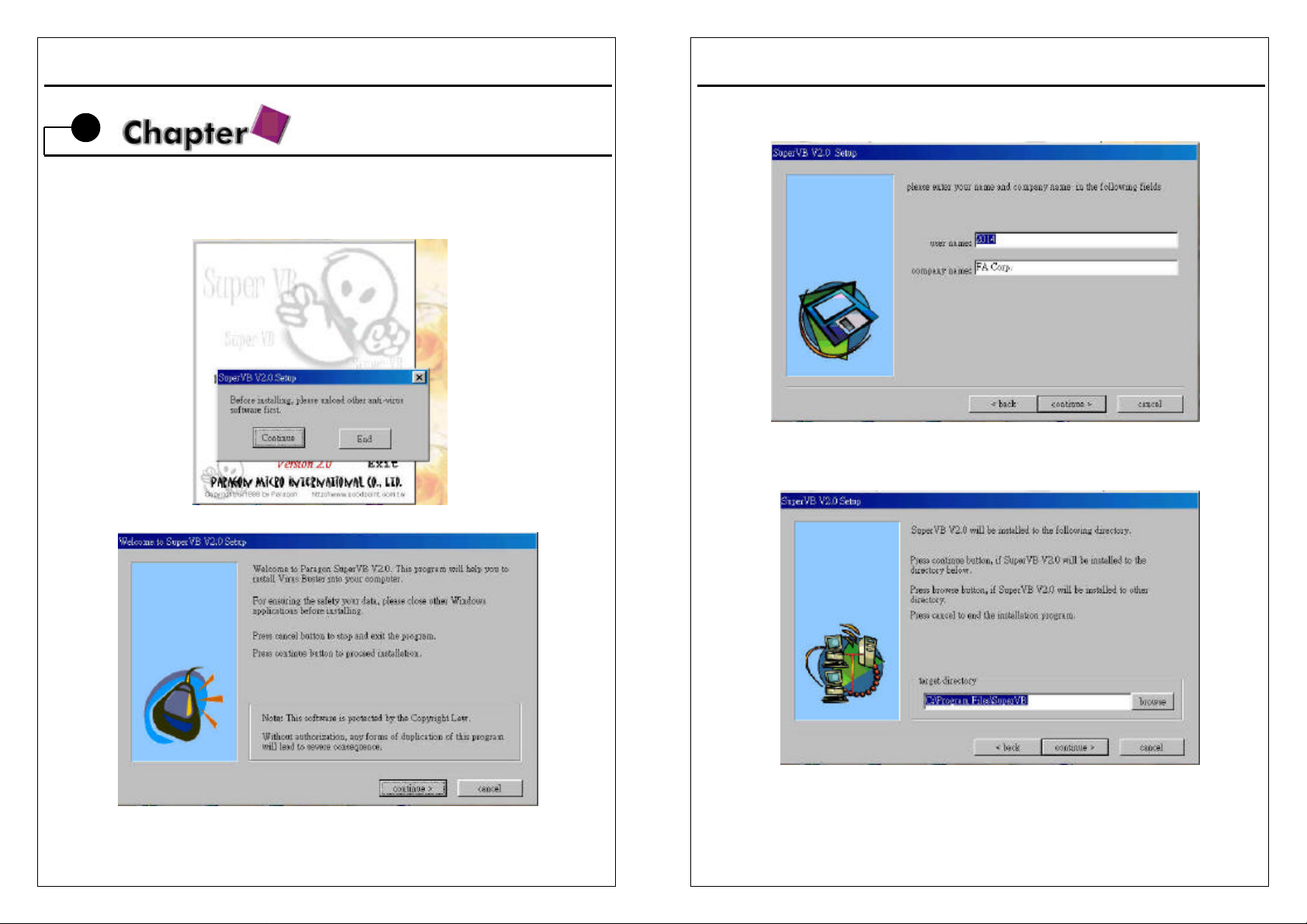
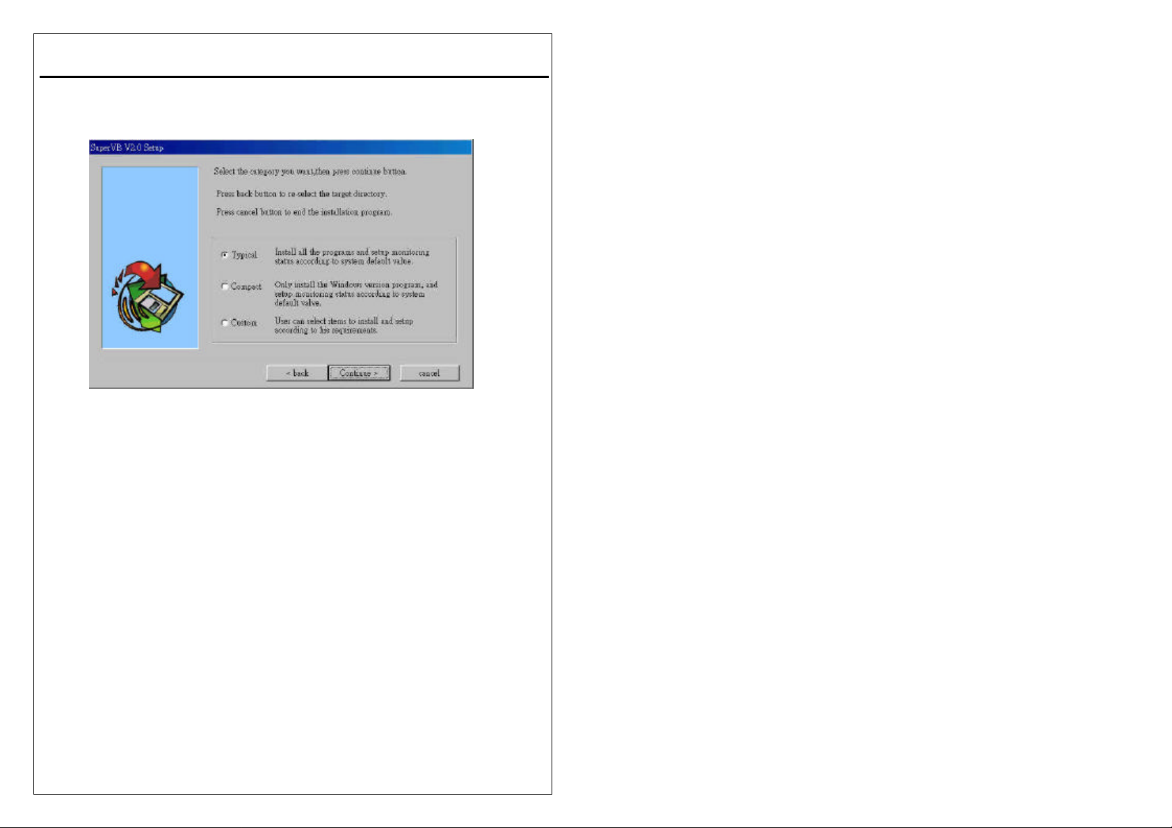
Put CD title driver into CD ROM, then choose “Anti-Virus software” on the main
menu, follow each instruction on the screen as the followings.
3VBAV User’s Manual
5-1
5-2
Page 37
3VBAV User’s Manual
5-3
 Loading...