

Page 1
User Manual
Text
( Rev.08.05.028)
Page 2

2
1. Safety Precautions
- Table of Contents -
1. Safety Precautions ................................ .................... 5
2. Specifications of the Drive ................................ ........... 7
2.1 Characteristic Table ................................ ............................ 7
2.2 Dimensions ................................ ................................ ...... 9
3. Specifications of the Motor ................................ .......... 10
3.1 BM-20 Series ................................ ................................ ....10
3.2 BM-28 Series ................................ ................................ ....11
3.3 BM-42 Series ................................ ................................ ....12
3.4 BM-56 Series ................................ ................................ ....13
3.5 BM-60 Series ................................ ................................ ....14
3.6 BM-86 Series ................................ ................................ ....15
4. Characteristics of Motor Torque ................................ ...... 16
5. Configuration of the Controller ................................ ...... 18
5.1 Combination of Motor and Drive ................................ ..................18
5.2 Controller Configuration ................................ ........................ 19
5.3 External Wiring Diagram ................................ ......................... 21
6. External Name and Function Setting of Ezi -STEP-PR ..................... 24
6.1 Appearance and Part Name ................................ ........................ 24
6.2 Status Display LED ................................ .............................. 25
6.3 Drive ID Select Switch(SW1) ................................ ..................... 25
6.4 Communication Speed and Terminal Resistance Select Switch(SW2) ...................25
6.5 Motor Connector(CN3) ................................ ............................ 26
6.6 Encoder Connector(CN2) ................................ .......................... 26
6.7 Power Connector(CN4) ................................ ............................ 26
6.8 I/O Signal Connector(CN1) ................................ ....................... 27
6.9 Communication Connector(CN5) ................................ .................... 27
7. External Name and Function Setting of Ezi -STEP-PR-MI .................. 28
www.fastech.co.kr
Page 3

3
1. Safety Precautions
7.1 Appearance and Part Name ................................ ........................ 28
7.2 Drive ID Switch Selection (SW1) and 7 -segmant ................................ ....28
7.3 Communication Speed and Terminal Resistance Select Switch(SW2) ...................28
7.4 Motor Connection (CN3) ................................ .......................... 29
7.5 Encoder Connection (CN2 ) ................................ ........................ 29
7.6 Power Connection(CN4) ................................ ........................... 29
7.7 I/O Signal Connection (CN1) ................................ ..................... 30
7.8 Communication Connecttion (CN5) ................................ .................30
8. Control I/O Signal ................................ ................... 31
8.1 Signal Cabling ................................ ................................ ..31
8.2 Connection Circuit ................................ .............................. 32
8.3 Input Signal ................................ ................................ ....34
8.4 Output Signal ................................ ................................ ...42
9. Operation ................................ ........................... 45
9.1 Power Supply Timing ................................ ............................. 45
9.2 STEP ON/OFF Operation ................................ ........................... 45
9.3 Operation Mode ................................ ................................ ..45
10. Other Operation Functions ................................ ........... 47
10.1 Position Table(PT) Operation Example ................................ ............47
10.2 Jog Operation Example ................................ .......................... 47
10.3 Origin Return ................................ ................................ ..48
10.4 Stop Operating ................................ ................................ .50
10.5 Trigger Pulse Output ................................ ........................... 50
11. Communication Function ................................ .............. 52
11.1 Connection with the PC ................................ ......................... 52
11.2 Communication Interface Circuit ................................ ................ 54
12. Protective Function ................................ ................. 55
12.1 Alarm Type ................................ ................................ .....55
12.2 Acquiring Alarm Information ................................ .................... 55
12.3 Alarm Reset ................................ ................................ ....56
13. Parameter ................................ .......................... 57
www.fastech.co.kr
Page 4

4
1. Safety Precautions
13.1 Parameter List ................................ ................................ .57
13.2 External Encoder Connection ................................ .................... 57
13.3 Parameter Description ................................ .......................... 58
Appendix ................................ ............................... 62
www.fastech.co.kr
Page 5
5
1. Safety Precautions
☞ Contents of this manual are subject to change without prior notice for functional
improvement, change of specifications, or user's better understanding.
Thoroughly Read the manual provided with the purchased Ezi - STEP.
☞ When the manual is damaged or lost, contact a FASTECH agent or the address on the
last page of the manual.
☞ FASTECH is not responsible for a product breakdown due to user's dismantling the
product, and such a breakdown is not covered by the warranty.
☞ Before installing, operating, and repairing the product, thoroughly read the manual
and fully understand contents. Before operating the product, understand the
mechanical characteristics of the product and related safety information and
precautions.
☞ After reading the manual, keep the manual near the product so that any user can read
the manual whenever needed.
☞ This manual divides safety precautions into 「Warning」 and 「Caution」.
If the user does improperly handle the product, the user may get
seriously or slightly injured and damages may occur in the machine
only.
If the user does improperly handle the product, a dangerous situation
like an electric shock may occu r resulting in death or serious
injuries.
Caution
Warning
Caution
Manual Version : [ver08.05.028]
Supported Firmware version : F06~
Supported Drive(DSP) software version : 6.3.066.36
Supported GUI version : 6.24.3.626 ~
Fisrt Edition : Oct 02, 2008
Revised Edition : June 20, 2013
1. Safety Precautions
※ Before getting started ※
l Thank you for purchasing Ezi-STEP of FASTECH, which is a full digital position
control servo system with a 32bit high performance DSP.
l This manual describes handling, maintenance, repair, diagnosis, and
troubleshooting of Ezi- STEP.
l Before operating Ezi- STEP, read this manual through.
◆ General Precautions
◆ Put the safety first
☞ Although the item mentioned is only , a serious result may be caused
depending on the situation. Necessarily follow safety precautions.
www.fastech.co.kr
Page 6
6
1. Safety Precautions
☞ Check if the product is dama ged or any component is omitted.
When an abnormal product is installed and operated, the user may get
injured.
☞ Carefully move the product.
Dropping the product on the ground or the user's foot may cause an
injury.
☞ Use non-flammable materials like metals in the place where the product
is to be installed.
Otherwise, a fire may occur.
☞ When installing several drives in a sealed place, install a cooling
fan to keep the ambient temperature of the drive at 50℃ or lower.
Otherwise, a fire o r other kinds of accidents may occur due to
overheating.
☞ Before connecting cables, check if input power is off.
Otherwise, an electric shock or a fire may occur.
☞ The case of the drive is insulated from the ground of the inte rnal
circuit by the condenser. Necessarily ground the driver.
Otherwise, an electric shock or a fire may occur.
☞ All parameters of the drive were accordingly set at the factory. To
change these parameters, read the manual first.
Otherwise, the machine may be damaged or out of order.
☞ Stop supplying power to the main circuit , wait for a while, and then
check or repair the drive.
Electricity remaining in the condenser may cause any danger like an
electric shock.
☞ Do not change cabling while power is being supplied.
Otherwise, the user may get injured or the drive may get damaged.
☞ Do not remodel the drive.
Otherwise, the user may receive an electric shock or the drive may
get damaged. The damaged product is not covered by the warranty.
Caution
Caution
Warning
Caution
Warning
◆ The Status of the Product
◆ Install
◆ Connecting Cables
◆ Change of operation and setting
◆ Repair and Check
Notes on Installation
1) This product has been designed for indoor uses. The ambient temperature of the room
should be 0℃~55℃.
2) If the temperature of the case is 50 ℃ or higher, radiate heat outside to cool down
the case.
3) Do not install this product under direct rays or near magnetic or radioactive
objects.
4) If more than 2 drives are installed in a line, keep the interval of 20mm or more
vertically and 50mm or more horizontally.
www.fastech.co.kr
Page 7
7
1. Safety Precautions
2. Specifications of the Dri ve
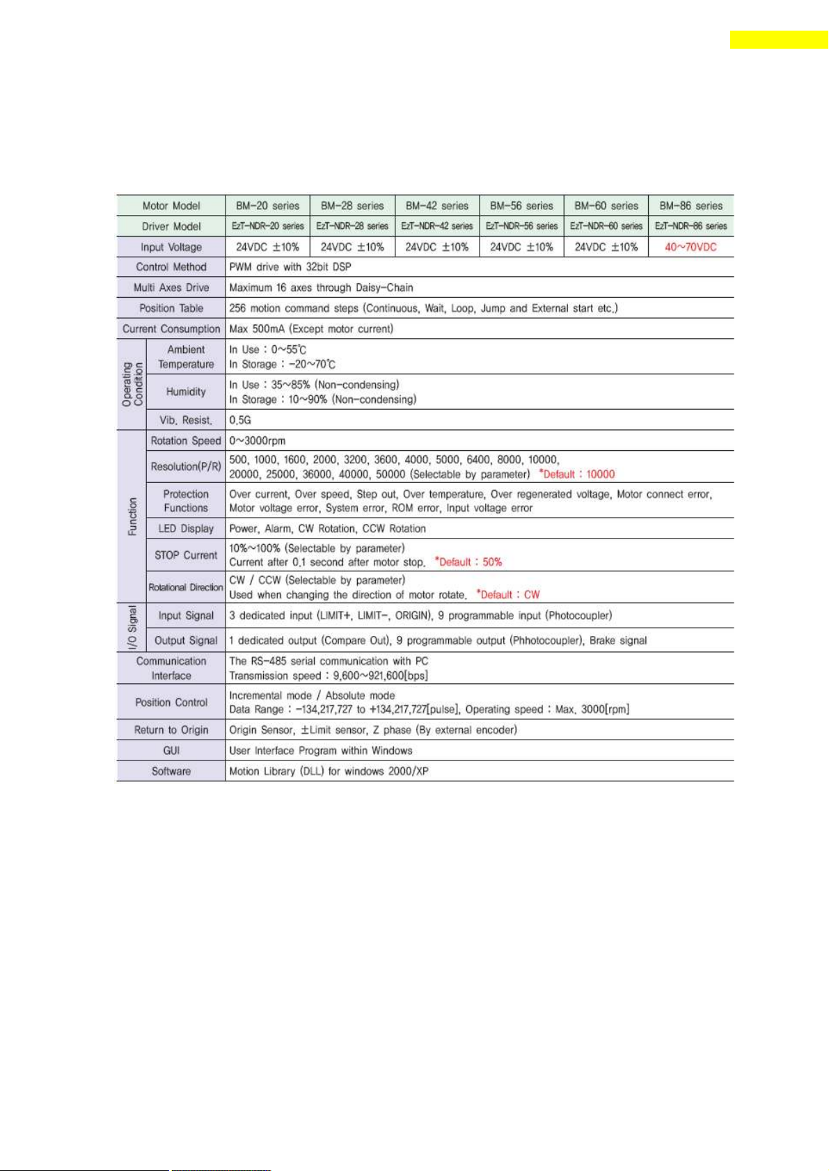
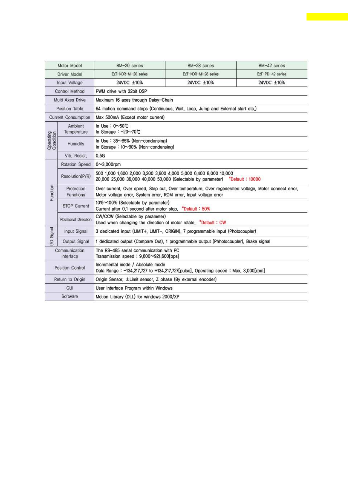
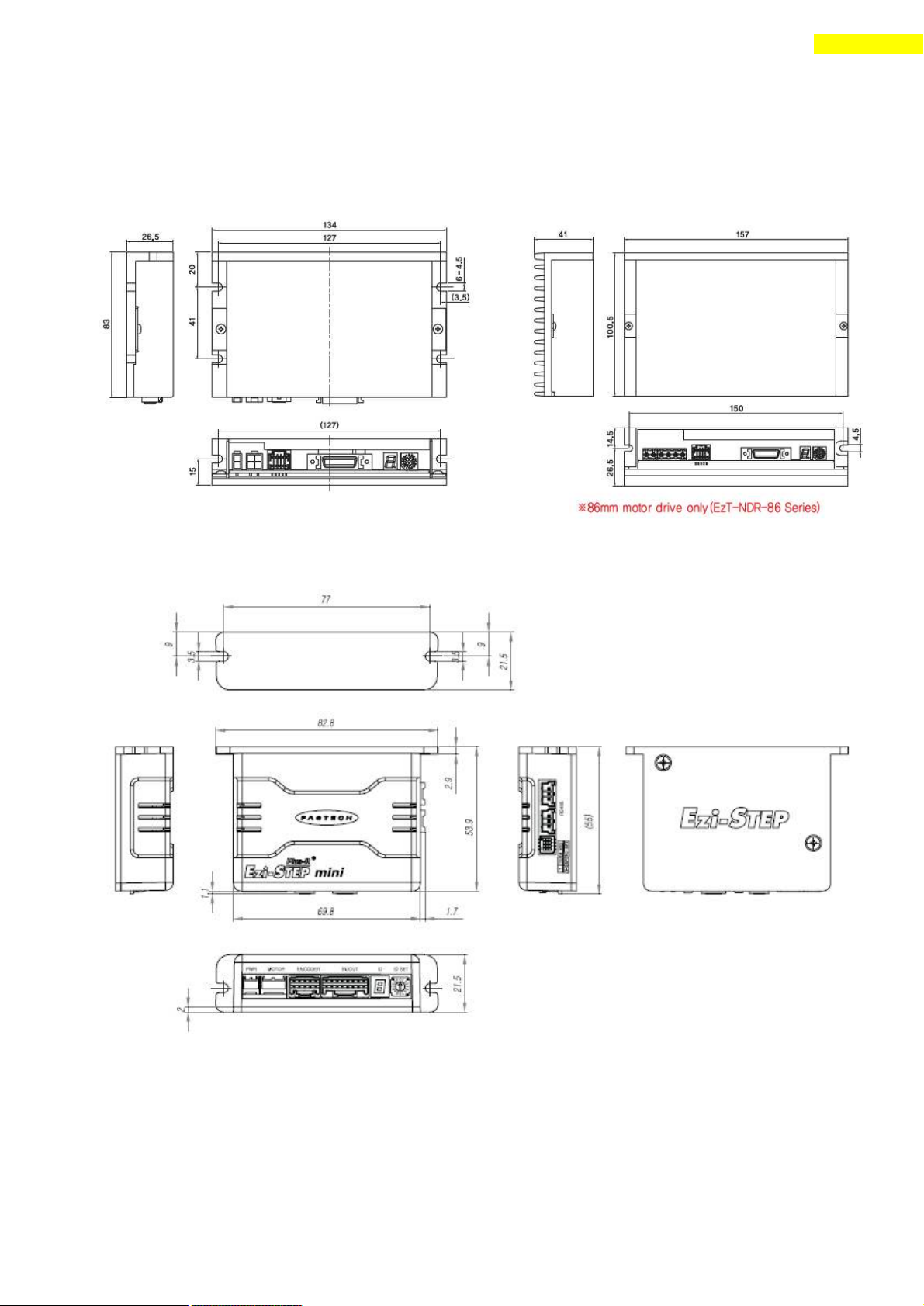
2.1 Characteristic Table
1) Ezi-STEP-PR
www.fastech.co.kr
Page 8
8
1. Safety Precautions
2) Ezi-STEP-PR-MI
www.fastech.co.kr
Page 9
9
1. Safety Precautions
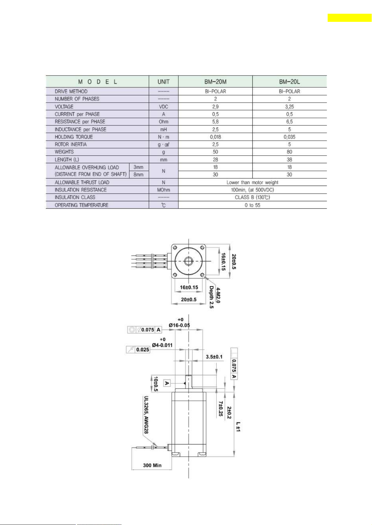
2.2 Dimensions
1) Ezi-STEP-PR
2) Ezi-STEP-PR-MI
www.fastech.co.kr
Page 10
10
3. Specifications of the Motor
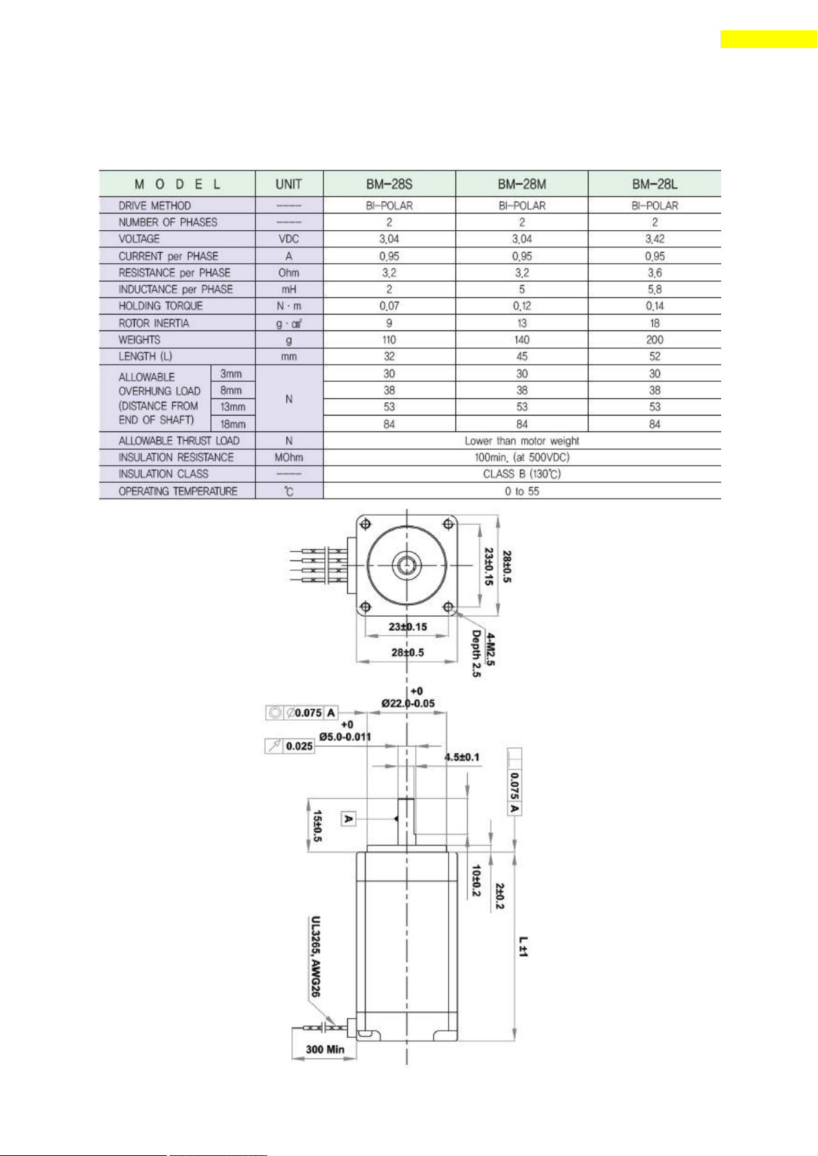
3. Specifications of the Motor
3.1 BM-20 Series
1) Specifications
2) Dimensions
www.fastech.co.kr
Page 11
11
3. Specifications of the Motor
3.2 BM-28 Series
1) Specifications
2) Dimensions
www.fastech.co.kr
Page 12
12
3. Specifications of the Motor
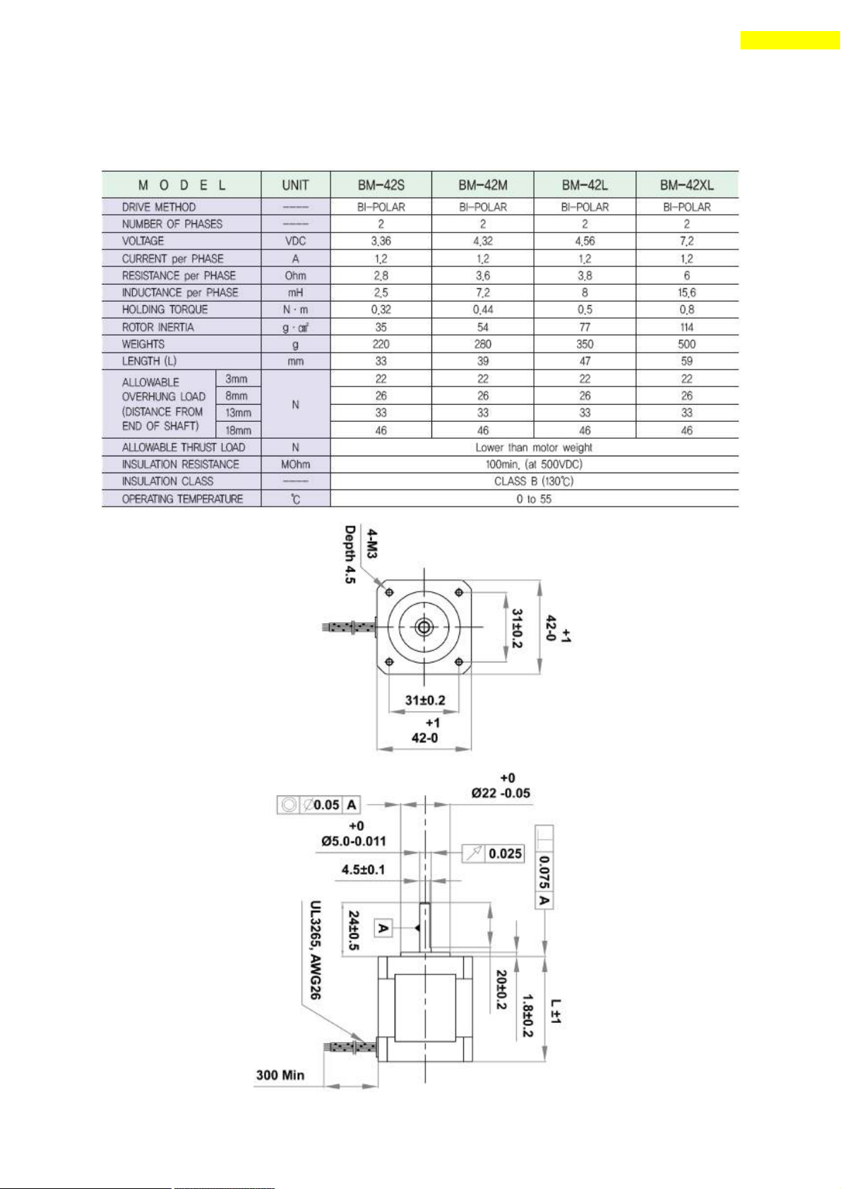
3.3 BM-42 Series
1) Specifications
2) Dimensions
www.fastech.co.kr
Page 13
13
3. Specifications of the Motor
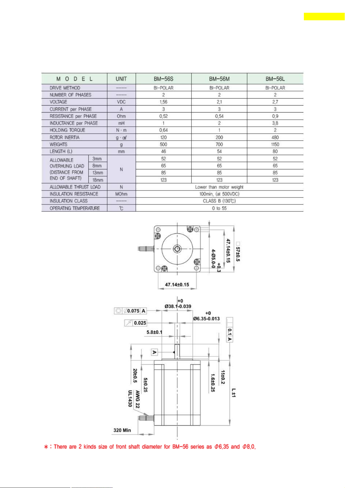
3.4 BM-56 Series
Ezi-STEP-PR drive only.
1) Specifications
2) Dimensions
www.fastech.co.kr
Page 14
14
3. Specifications of the Motor
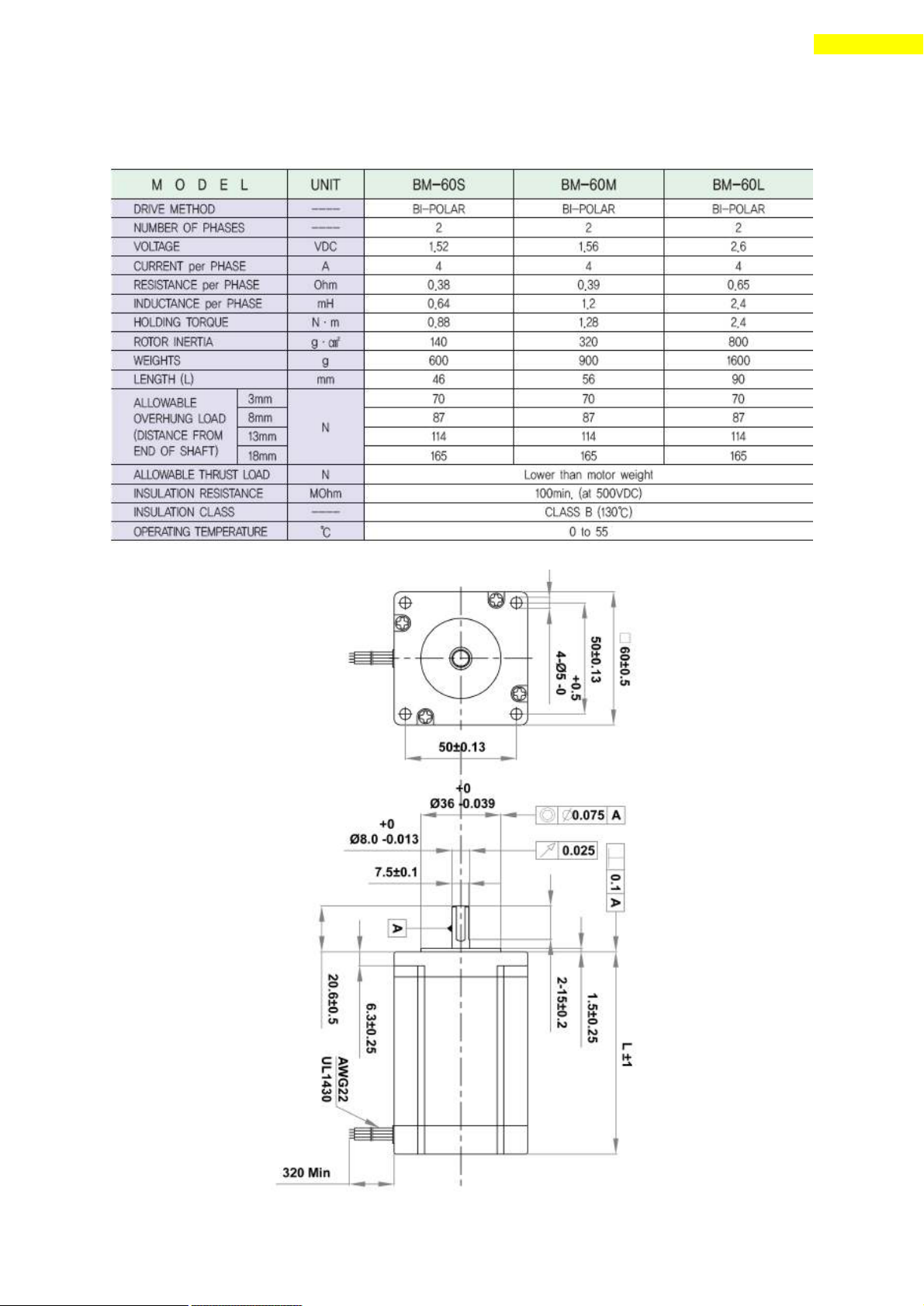
3.5 BM-60 Series
Ezi-STEP-PR drive only.
1) Specifications
2) Dimensions
www.fastech.co.kr
Page 15
15
3. Specifications of the Motor
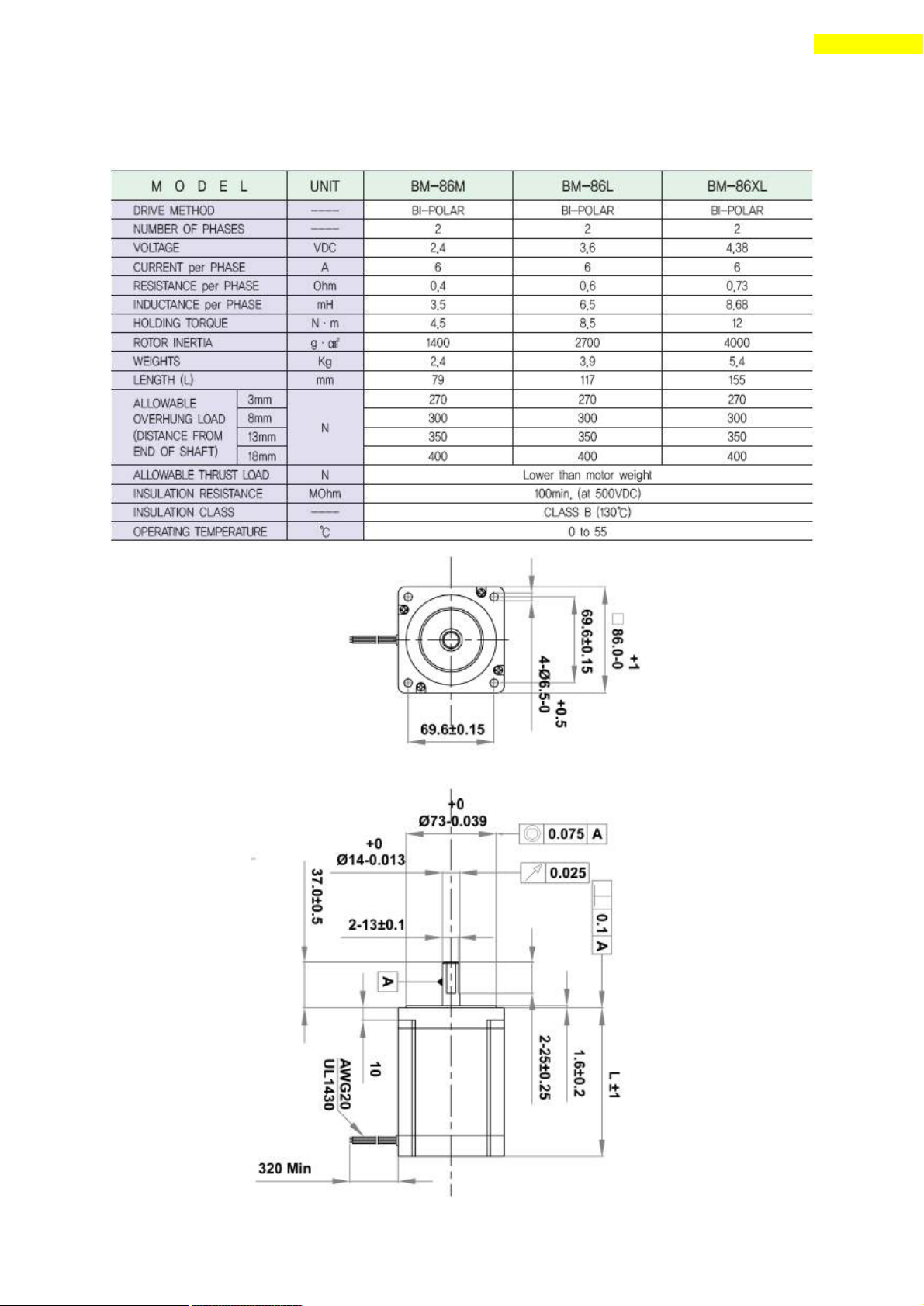
3.6 BM-86 Series
Ezi-STEP-PR drive only.
1) Specifications
2) Dimensions
www.fastech.co.kr
Page 16
16
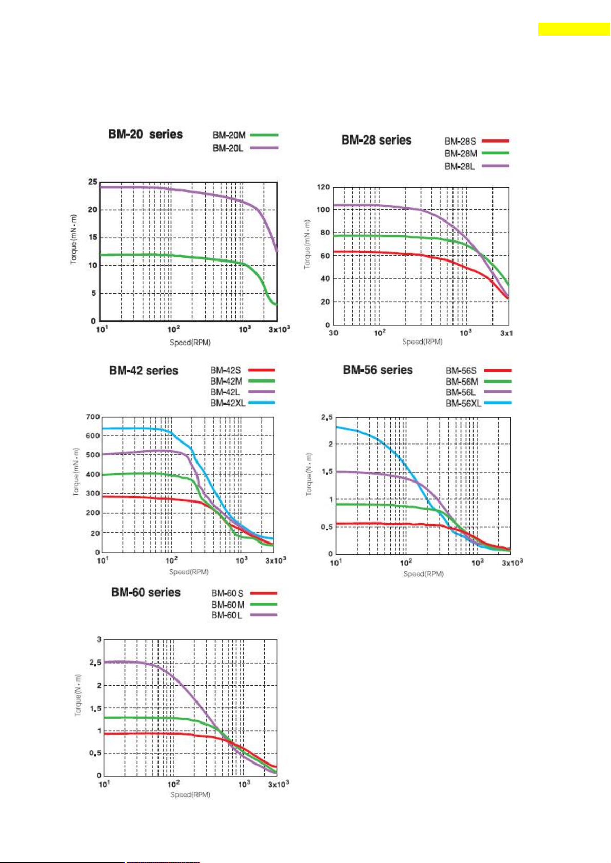
4. Characteristics of Motor Torque
4. Characteristics of Motor Torque
Measured condition : Motor Voltage=24VDC
Motor Current=Rated Current (refer to motor speci fication)
BM-56 series :Ezi-STEP-PR drive only.
BM-60 series :Ezi-STEP-PR drive only.
www.fastech.co.kr
Page 17
17
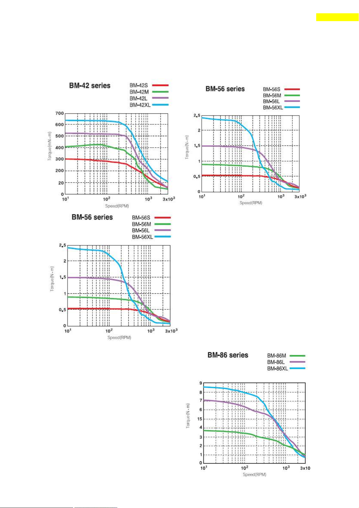
4. Characteristics of Motor Torque
Measured condition : Motor Voltage=40VDC
Motor Current=Rated Current (refer to motor specification)
Measured condition :
Motor Voltage=70VDC
Motor Current=Rated Current
(refer to motor specification)
www.fastech.co.kr
Page 18
18
5. Configuration of the Controller
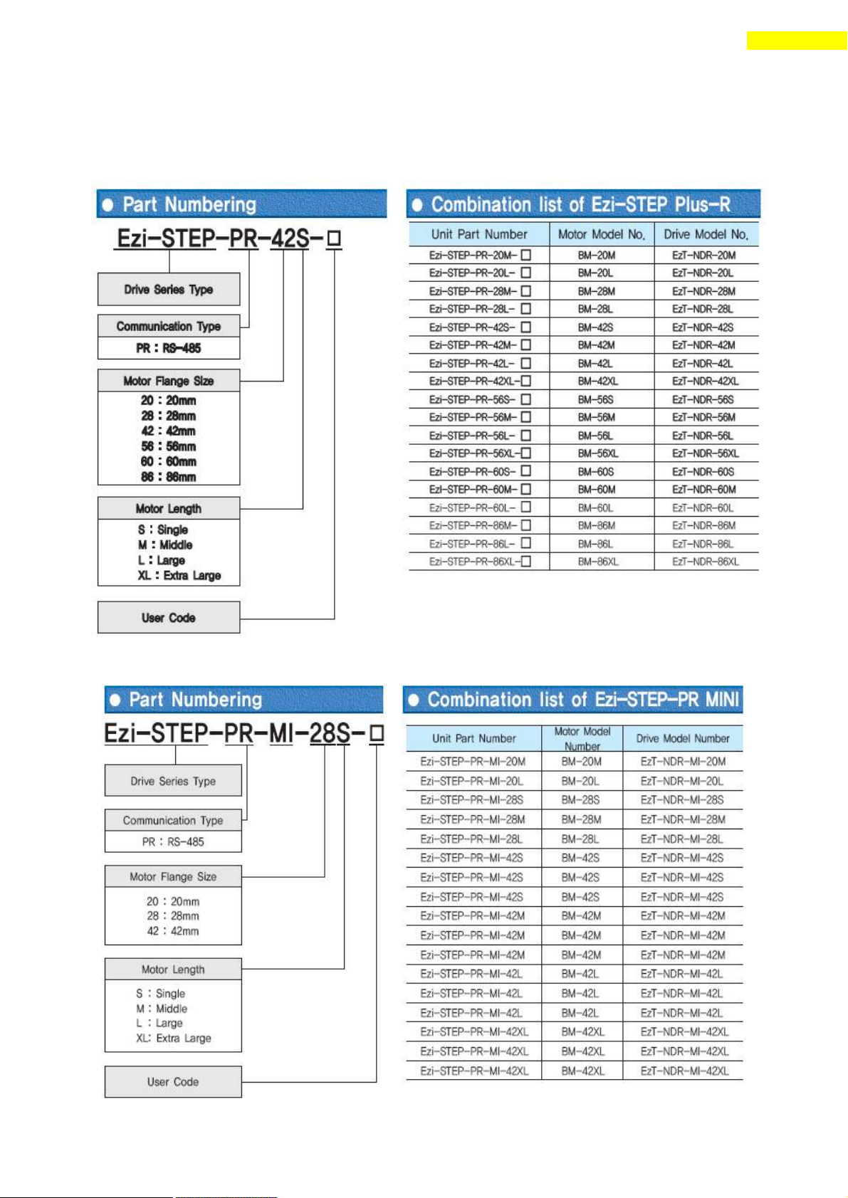
5. Configuration of the Controller
5.1 Combination of Motor and Drive
1) Ezi-STEP-PR
2) Ezi-STEP-PR-MI
www.fastech.co.kr
Page 19
19
5. Configuration of the Controller
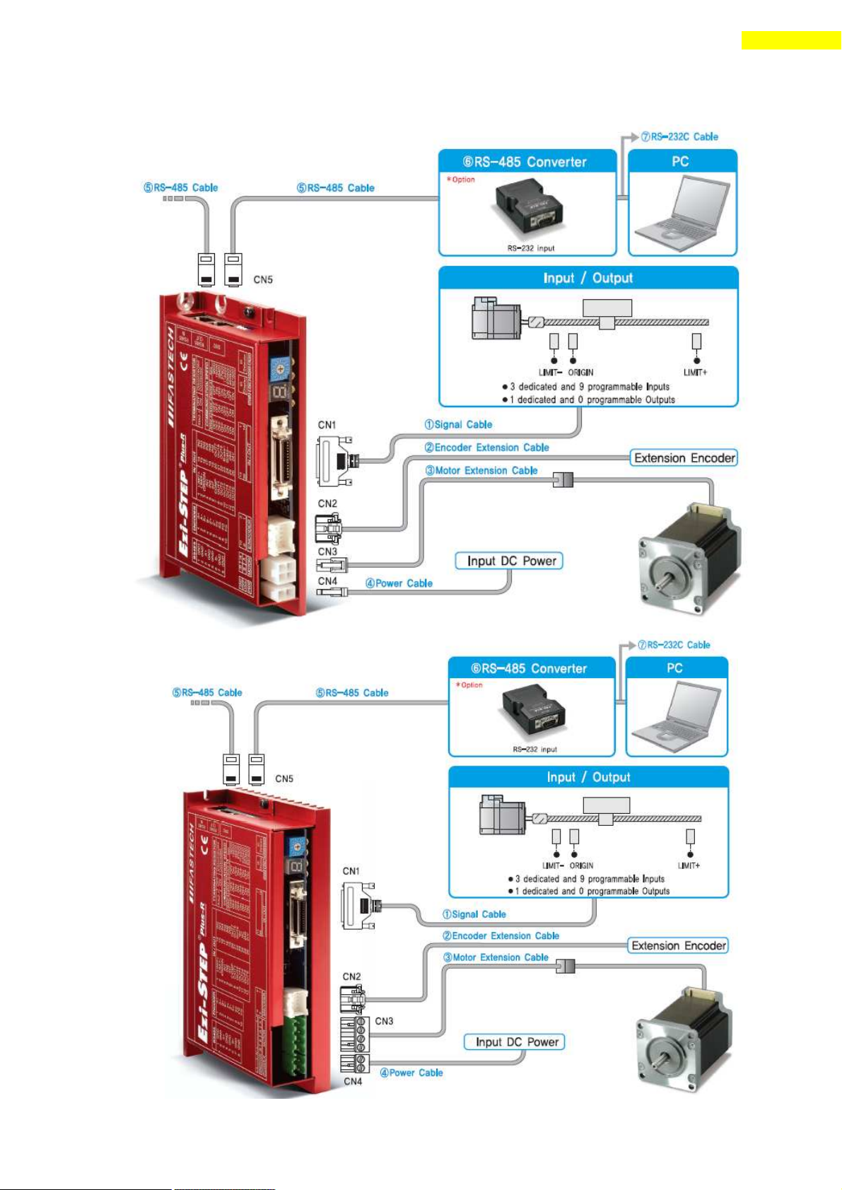
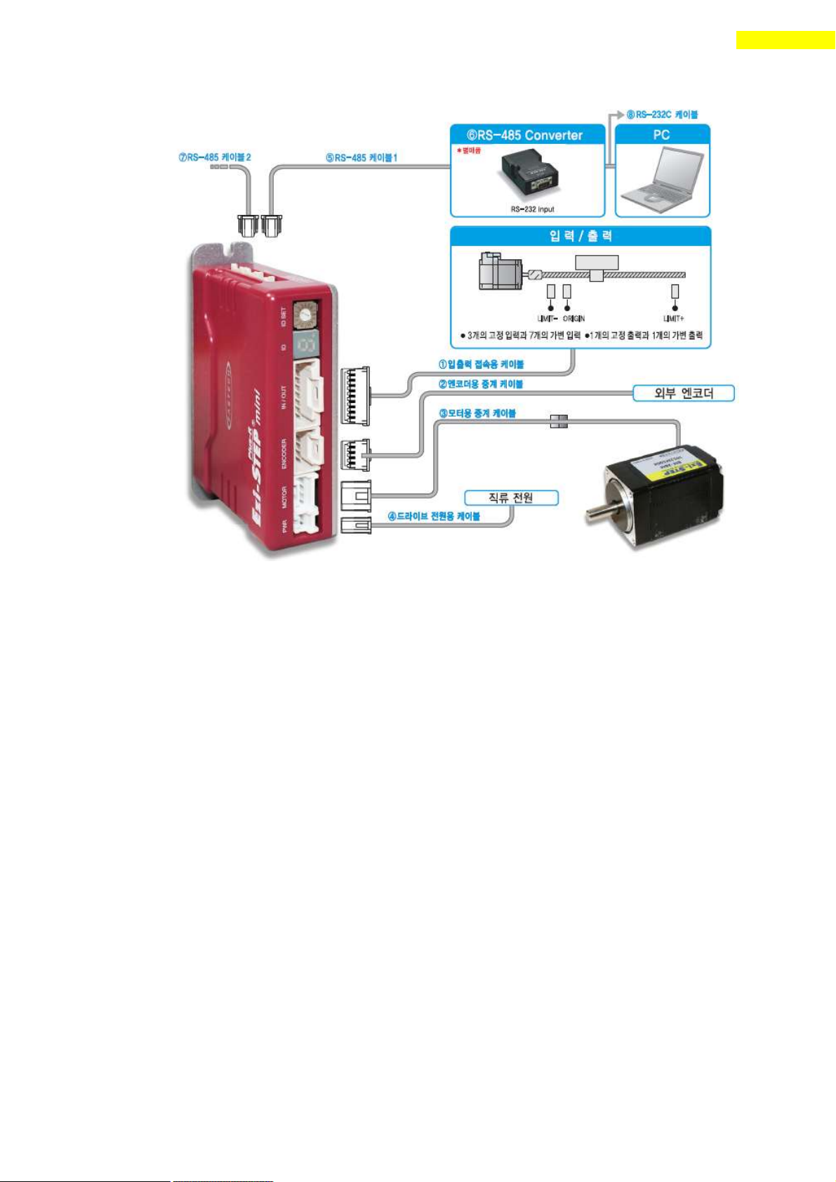
5.2 Controller Configuration
1) Configuration of Ezi-STEP-PR20/ Ezi-STEP-PR28/ Ezi-STEP-PR42/ Ezi-STEP-PR56
Ezi-STEP-PR60
2) Configuration of Ezi-STEP-PR86
www.fastech.co.kr
Page 20
20
5. Configuration of the Controller
3) Configuration of Ezi-STEP-PR-MI
www.fastech.co.kr
Page 21
21
5. Configuration of the Controller
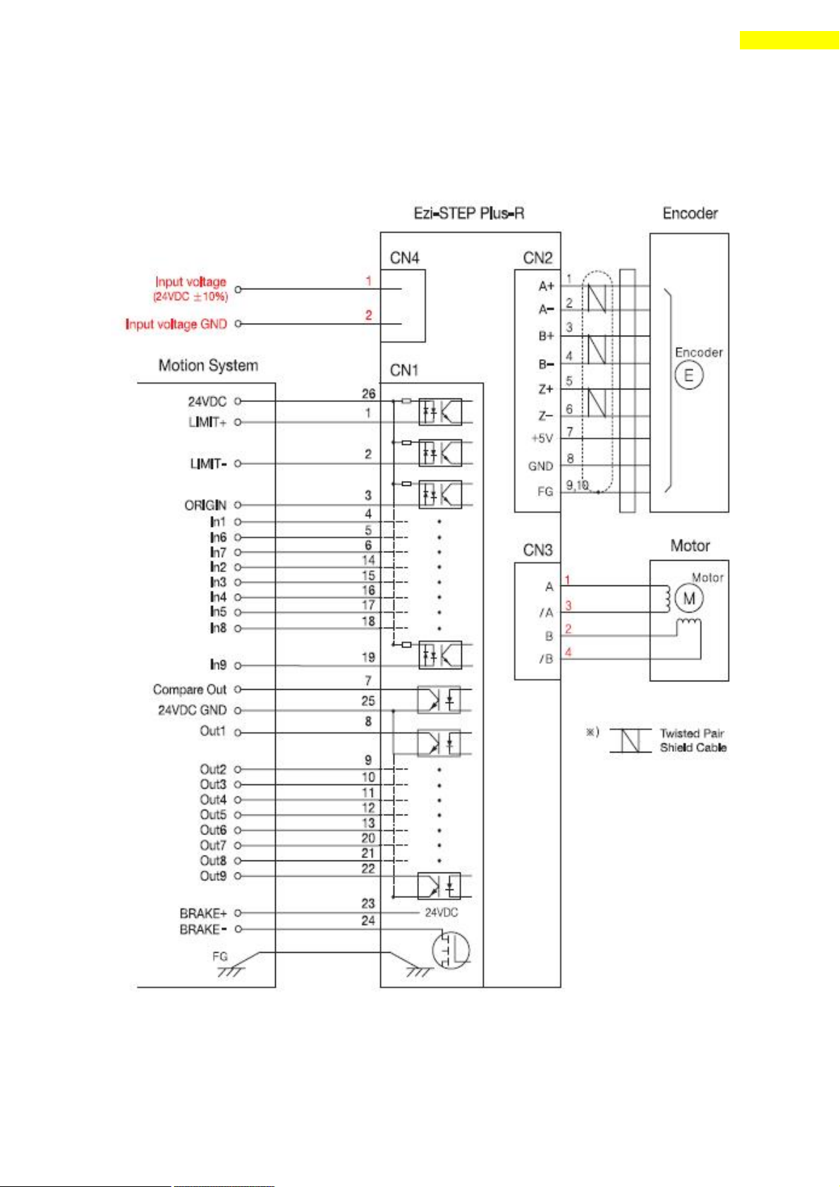
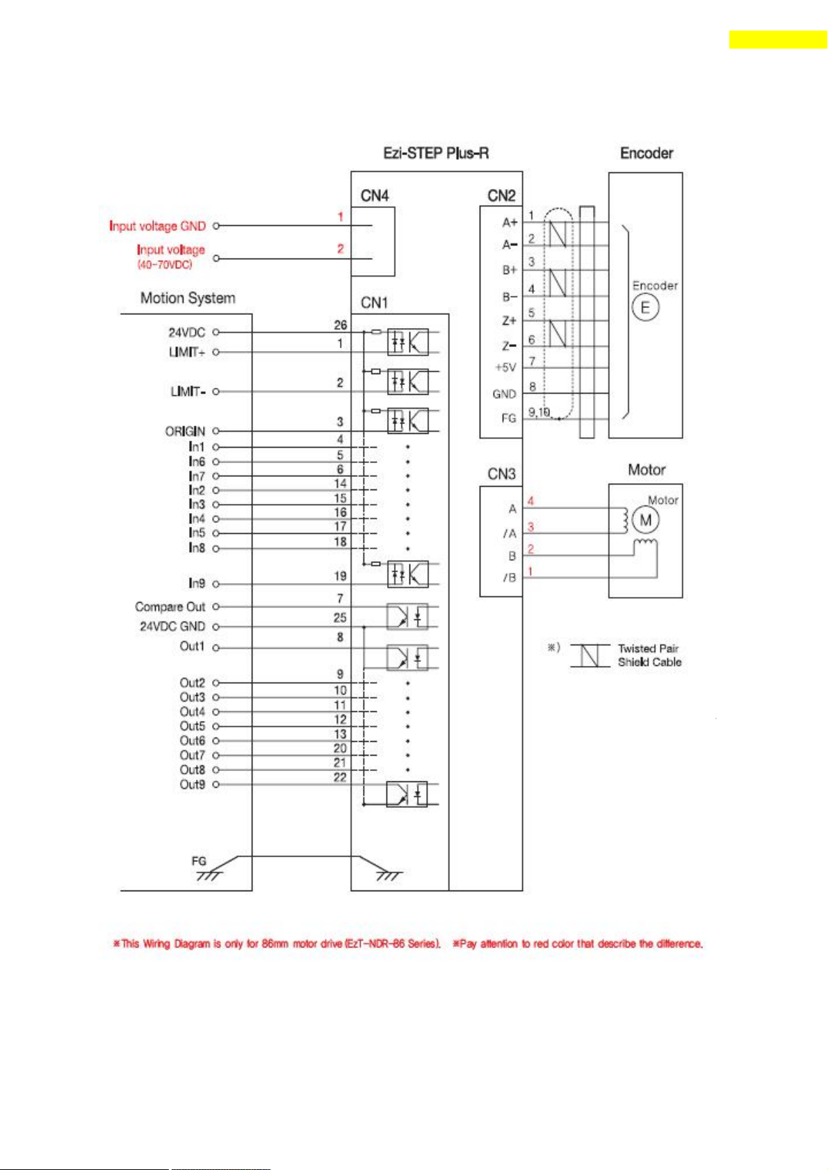
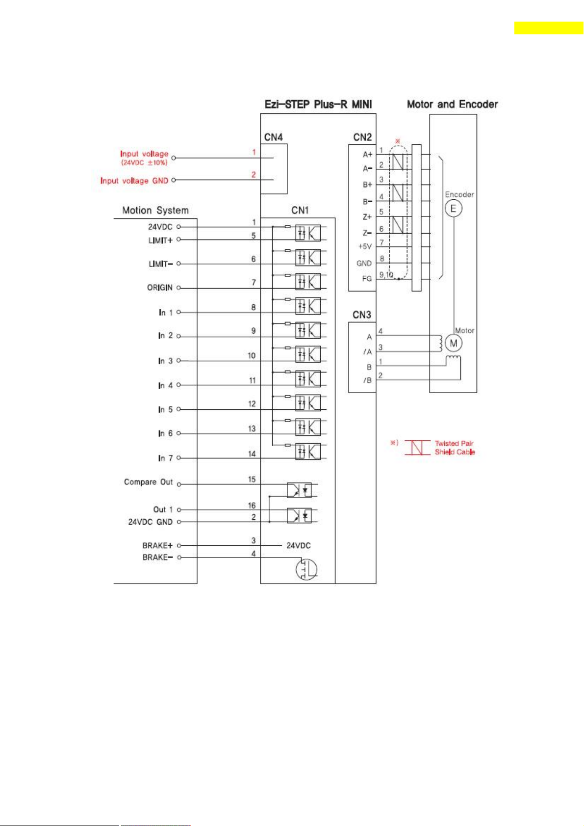
5.3 External Wiring Diagram
1) Diagram of Ezi-STEP-PR20/ Ezi-STEP-PR28/ Ezi-STEP-PR42/ Ezi-STEP-PR56
Ezi-STEP-PR60
www.fastech.co.kr
Page 22
22
5. Configuration of the Controller
2) Diagram of Ezi-STEP-PR86
www.fastech.co.kr
Page 23
23
5. Configuration of the Controller
3) Diagram of Ezi-STEP-PR-MI
www.fastech.co.kr
Page 24
24
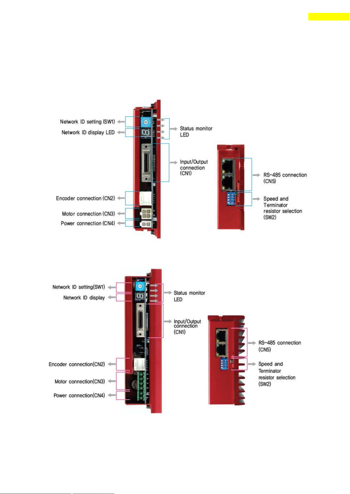
6. External Name and Function Setting of Ezi-STEP-PR
6. External Name and Function Setting of Ezi-STEP-PR
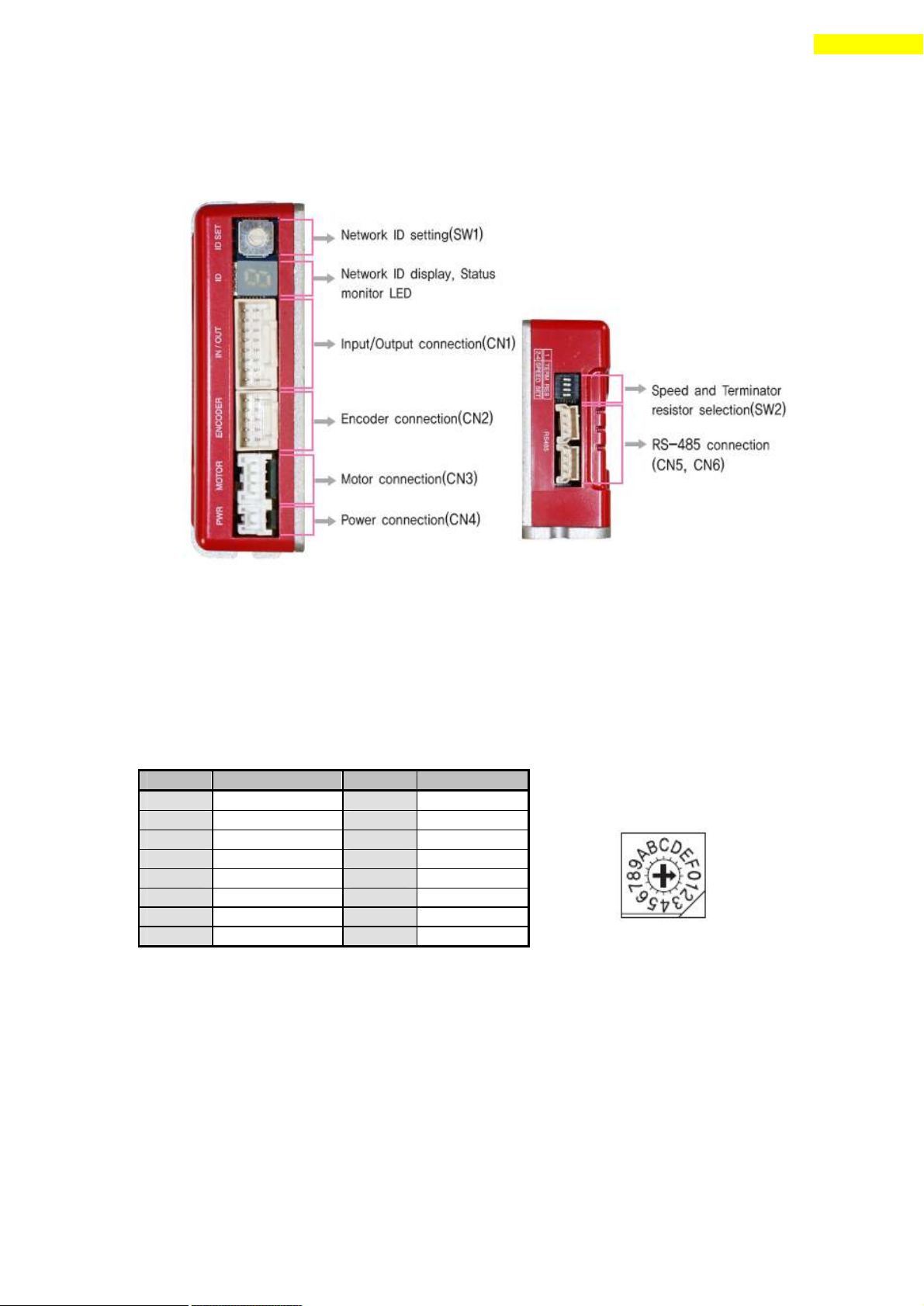
6.1 Appearance and Part Name
1) Ezi-STEP-PR20/ Ezi-STEP-PR28/ Ezi-STEP-PR42/ Ezi-STEP-PR56
Ezi-STEP-PR60
1) Ezi-STEP-PR86
www.fastech.co.kr
Page 25
25
6. External Name and Function Setting of Ezi-STEP-PR
Position
ID No.
Position
ID No.
0 0 8
8
1 1 9
9
2 2 A
10
3 3 B
11
4 4 C
12
5 5 D
13
6 6 E
14
7 7 F
15
The communication speed of drive modules connected to one segment must
be set to the same value.
Support max. 115200[bps] when using RS -232 to RS-485 conveter
SW2.1
SW2.2
SW2.3
SW2.4
Baud rate
[bps]
*1 : default setting value.
SW2.1 is OFF.: Terminator resistor is Off.
SW2.1 is ON. : Terminator resistor is On.
X
OFF
OFF
OFF
9600
X
ON
OFF
OFF
19200
X
OFF
ON
OFF
38400
X
ON
ON
OFF
57600
X
OFF
OFF
ON
115200 *1
X
ON
OFF
ON
230400
X
OFF
ON
ON
460800
X
ON
ON
ON
921600
Caution
Caution
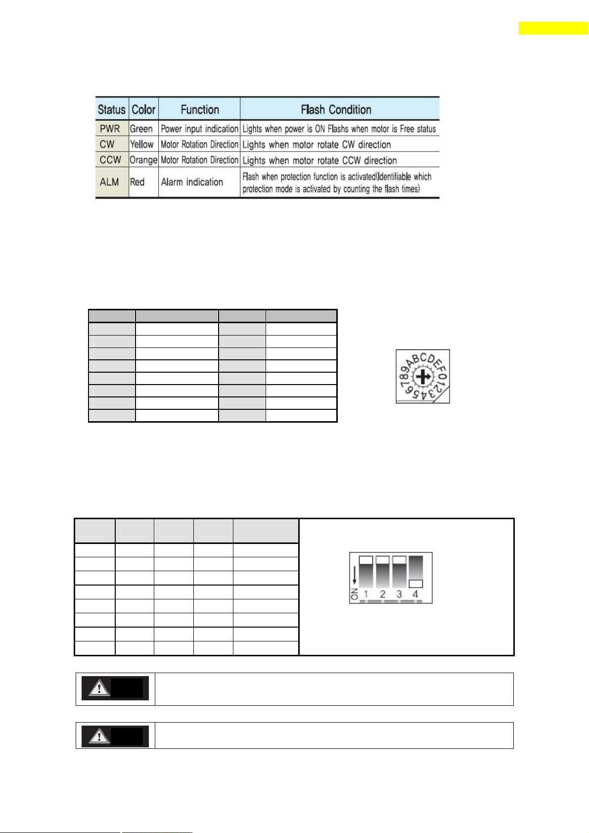
6.2 Status Display LED
6.3 Drive ID Select Switch(SW1)
1) When several modules are connected to one daisy chain network, this switch is to
set intrinsic ID to each module.
2) The switch can set intrinsic ID to each module up to 16 numbers from 0 to F(15).
6.4 Communication Speed and Terminal Resistance Select Switch (SW2)
SW2 is to set the communication speed between central controller (PC) and Drive. If
corresponding drive module is connected to the end of one network segment, SW2 sets
whether terminal resis tance is used. SW2.1 is to set the use of terminal resistance,
and SW2.2~SW2.4 is to set the communication speed as follows.
www.fastech.co.kr
Page 26
26
6. External Name and Function Setting of Ezi-STEP-PR
No.
Function
1
A+
2
A-
3
B+
4
B-
5
Z+
6
Z-
7
5VDC
8
5VDC GND
9
Frame GND
10
Frame GND
No.
Function
1
A Phase
2
B Phase
3
/A Phase
4
/B Phase
No.
Function
1
/B Phase
2
B Phase
3
/A Phase
4
A Phase
No.
Function
1
Power input : 24VDC ± 10%
2
Power input : GND
No.
Function
1
Power input : GND
2
Power input : 24VDC ± 10%
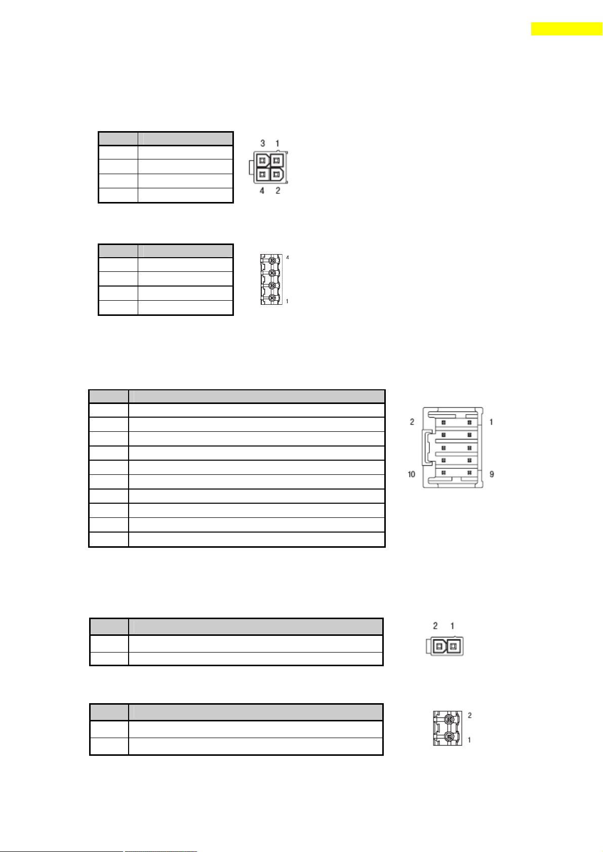
6.5 Motor Connector(CN3)
Motor connector
(Connector Type : Molex 5569-04A2)
(86mm)
6.6 Encoder Connector(CN2)
Used for monitoring the external encoder signal.
Encoder connector (Connector Type : Molex 55959-1030)
For setup of connected encoder resolution, refer to 「12 Parameter」.
6.7 Power Connector(CN4)
Power supply connector ( Connector Type : Molex 5569-02A2)
(86mm)
www.fastech.co.kr
Page 27
27
6. External Name and Function Setting of Ezi-STEP-PR
Connect the Brake (current consumption is under 200[mA]) for pin 24.
Refer to 7.4 Output signal for the Brake that is over 200[mA].
Function
No
No
Function
LIMIT+ (Dedicated Input)
1
14
Digital In2 ( Programmable Input)
LIMIT- (Dedicated Input)
2
15
Digital In3 ( Programmable Input)
ORIGIN (Dedicated Input)
3
16
Digital In4 ( Programmable Input)
Digital In1 (Programmable Input)
4
17
Digital In5 ( Programmable Input)
Digital In6 (Programmable Input)
5
18
Digital In8 ( Programmable Input)
Digital In7 (Programmable Input)
6
19
Digital In9 ( Programmable Input)
Compare Out (Dedicated Output)
7
20
Digital Out7 ( Programmable Output)
Digital Out1 (Programmable Output)
8
21
Digital Out8 ( Programmable Output)
Digital Out2 (Programmable Output)
9
22
Digital Out9 ( Programmable Output)
Digital Out3 (Programmable Output)
10
23
+24V for brake system( Output )
Digital Out4 (Programmable Output)
11
24
Control signal of brake system(Output)
Digital Out5 (Programmable Output)
12
25
GND external(Input)
Digital Out6 (Programmable Output)
13
26
+24V external(Input)
* This connector fixed pin is connected to frame GND through a mount hall.
Pin No.
Function
1,2,4,5,7,8
GND
3
Data+
6
Data-
case
Frame GND
LED No.
Display
Color
Lighting Condition
1,3
RUN
Green
Flash when CPU in the drive operates
2,4
COMM
Yellow
Flash when this communicates with the
upper controller
Caution
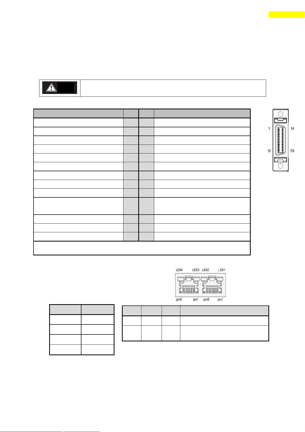
6.8 I/O Signal Connector(CN1)
Input/output signal connector ( Connector Type : 3M 10226-5A2JL)
The programmable input/output pin is set by using user program(GUI) or DLL library.
6.9 Communication Connector(CN5)
Connector Type : RJ45
Cable Type : UTP/STP CAT5E
www.fastech.co.kr
Page 28
28
7. External Name and Function Setting of Ezi-STEP-PR-MI
Position
ID No.
Position
ID No.
0 0 8
8
1 1 9
9
2 2 A
10
3 3 B
11
4 4 C
12
5 5 D
13
6 6 E
14
7 7 F
15
7. External Name and Function Setting of Ezi -STEP-PR-MI
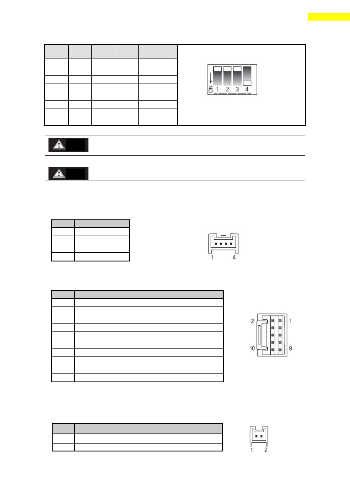
7.1 Appearance and Part Name
7.2 Drive ID Switch Selection (SW1) and 7 -segmant
1) When several modules are connected to one daisy chain network, this switch is to
set intrinsic ID to each module.
2) The switch can set intrinsic ID to each module up to 16 numbers from 0 to F(15).
3) 7-segmant of status monitor is display the ID number in normal status, but in
alarm status it display the protection number by flash times.
7.3 Communication Speed and Terminal Resistance Select Switch(SW2)
SW2 is to set the communication speed between central controller(PC) and Drive. If
corresponding drive module is connected to the end of one network segment, SW2 sets
whether terminal resis tance is used. SW2.1 is to set the use of terminal resistance,
and SW2.2~SW2.4 is to set the communication speed as follows .
www.fastech.co.kr
Page 29
29
7. External Name and Function Setting of Ezi-STEP-PR-MI
The communication speed of drive modules connected to one segment must
be set with same value.
Support max. 115200[bps] when using RS -232 to RS-485 conveter
No.
Function
1
B Phase
2
A Phase
3
/A Phase
4
/B Phase
No.
Function
1
A+
2
A-
3
B+
4
B-
5
Z+
6
Z-
7
5VDC
8
5VDC GND
9
Frame GND
10
Frame GND
SW2.1
SW2.2
SW2.3
SW2.4
Baud rate
[bps]
*1 : default setting value.
.
SW2.1 is OFF.: Terminal resistance is Off.
SW2.1 is ON. : Terminal resistance is On.
X
OFF
OFF
OFF
9600
X
ON
OFF
OFF
19200
X
OFF
ON
OFF
38400
X
ON
ON
OFF
57600
X
OFF
OFF
ON
115200 *1
X
ON
OFF
ON
230400
X
OFF
ON
ON
460800
X
ON
ON
ON
921600
No.
Function
1
Power input : 24VDC ± 10%
2
Power input : GND
Caution
Caution
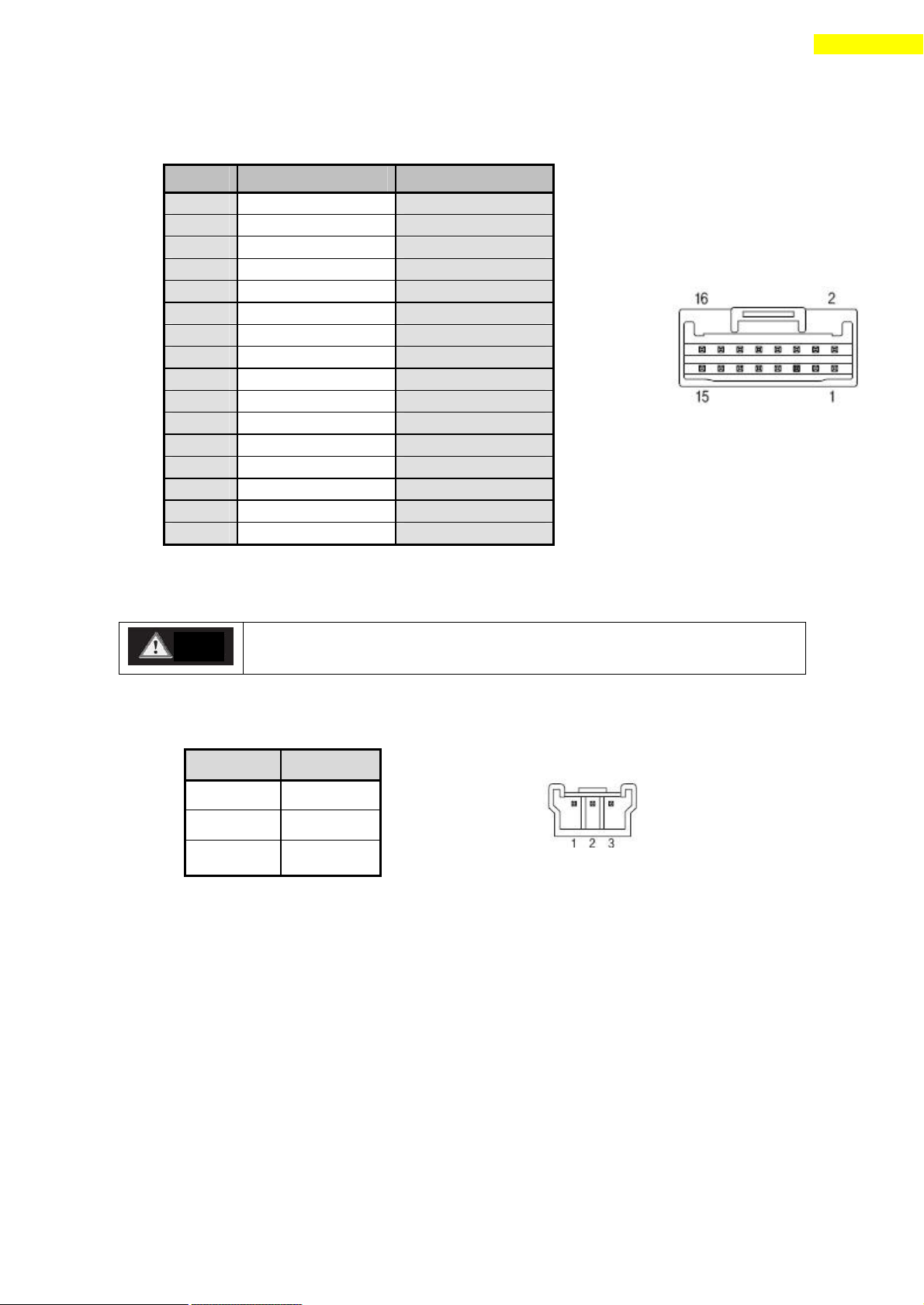
7.4 Motor Connection (CN3)
7.5 Encoder Connection (CN2)
To setup connected encoder resolution, refer to 「13 Parameter」.
7.6 Power Connection(CN4)
www.fastech.co.kr
Page 30
30
7. External Name and Function Setting of Ezi-STEP-PR-MI
No.
Function
Input/Output
1
24VDC
Input
2
24VDC GND
Input
3
BRAKE+
Output
4
BRAKE-
Output
5
+Limit sensor
Input
6
-Limit sensor
Input
7
Origin sensor
Input
8
Digital IN1
Input
9
Digital IN2
Input
10
Digital IN3
Input
11
Digital IN4
Input
12
Digital IN5
Input
13
Digital IN6
Input
14
Digital IN7
Input
15
Comapre Out (COMP)
Output
16
Digital OUT1
Output
Connect the Brake (current consumption is under 200[mA]) for pin 24.
Refer to 8.4 Output signal for the Brake that is over 200[mA].
No.
Function
1
Data+
2
Data-
3
GND
Caution
7.7 I/O Signal Connection (CN1)
The programmable input/output pin is set by using user program(GUI) or DLL library.
7.8 Communication Con necttion (CN5)
www.fastech.co.kr
Page 31
31
8. Control I/O Signal
Ezi-STEP-PR
CN1 No.
Ezi-STEP-PR-
MI
CN1 No.
Signal
Name
Function
1
5
Limit+
Positive limit sensor signal
2
6
Limit-
Negative limit sensor signal
3
7
Origin
Origin sensor signal
4
8
IN1
Clear Pos
Position table A0 ~ Position table A7 (PT A0~PT A7)
Position table start execution (PT Start)
Soft Stop(Stop)
Jog+
JogAlarmReset
Pause
Origin Search
Teaching
Emergency Stop(E-Stop)
Jump Position Table input 0 ~ Jump Position Table input 2
(JPT IN 0~ JPT IN 2)
Jump Position Table start (JPT St art)
User input 0 ~ User input 5 (User IN 0 ~ User IN 5)
14
9
IN2
15
10
IN3
16
11
IN4
17
12
IN5
5
13
IN6
6
14
IN7
18
None
IN8
19
None
IN9
Ezi-SERVO-PR
CN1 No.
Ezi-SERVO-MI-PR
CN1 No.
Signal
Name
Function
7
15
COMP
Specific output signal (Compare Out)
8
16
OUT1
InPosition
Alarm
Moving
Acc/Dec
ACK
END
AlarmBlink
OriginSearchOK
ServoReady
Brake
Position Table output 0 ~ Position Table output 2
(PT OUT 0 ~ PT OUT 2)
User Output 0 ~ User Output 8
9
None
OUT2
10
None
OUT3
11
None
OUT4
12
None
OUT5
13
None
OUT6
20
None
OUT7
21
None
OUT8
22
None
OUT9
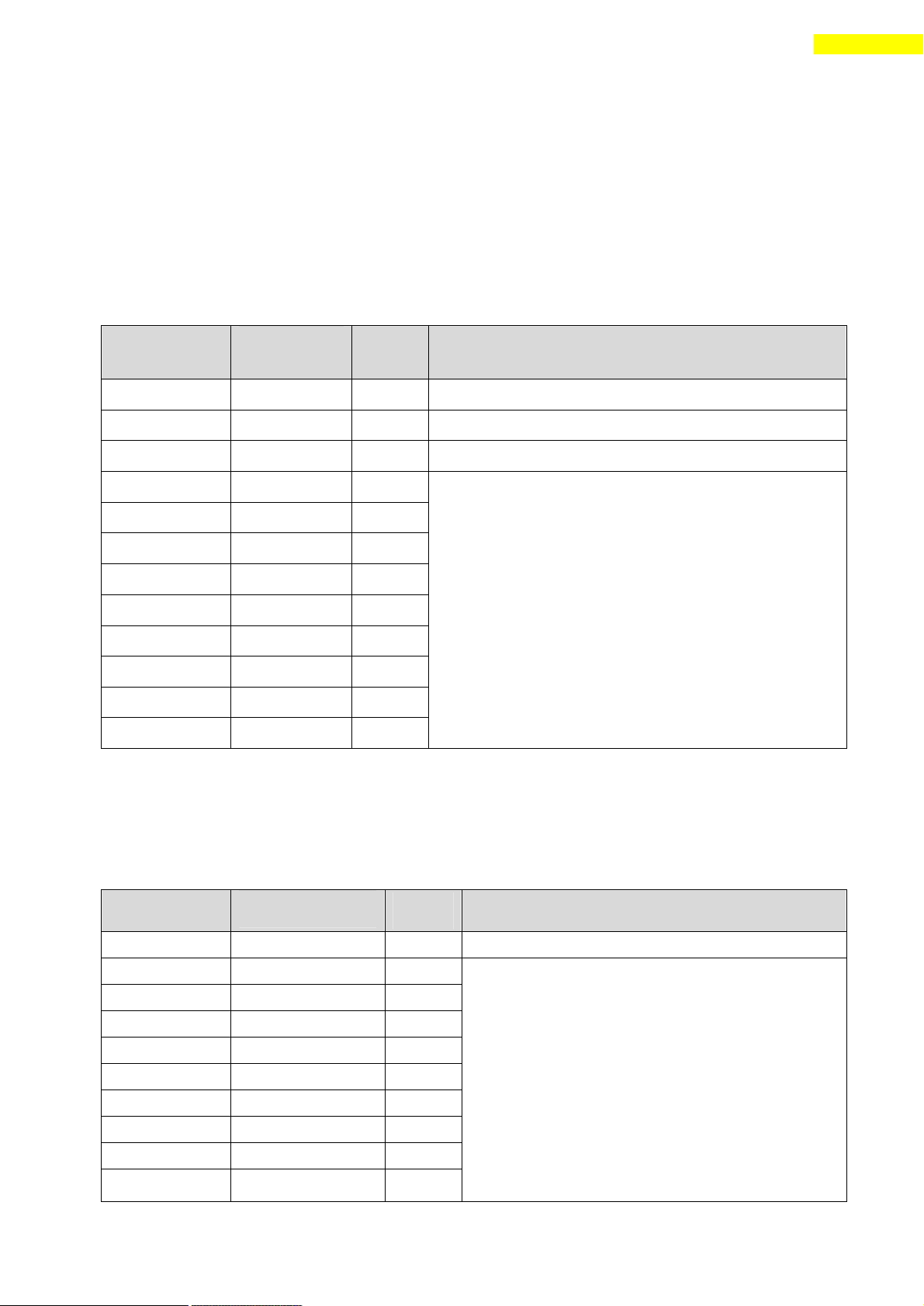
8. Control I/O Signal
8.1 Signal Cabling
All control I/O signals use connector CN1 as specified below.
1) Input : 「Limit+」, 「Limit-」, 「Origin」 signals are fixed to CN1 No. 1,2,3
respectively. Other signals like Reset are assigned to IN1~IN9 terminal blocks.
(3 dedicated input + 9 programmable input = total 12 input pins.)
Ezi-STEP-PR : 3 dedicated In + 9 programmable In = 12 Inputs
Ezi-STEP-PR-MI : 3 dedicated In + 7 programma ble In = 10 Inputs
2) Output : 「COMP」 signal is dedicated to CN1 No.7. Other signals like
Alarm are assigned to OUT1~OUT9 terminal blocks.
Ezi-STEP-PR : 1 dedicated Out + 9 programmable Out = 10 Outputs
Ezi-STEP-PR-MI : 1 dedicated Out + 1 programmable Out = 2 Outputs
www.fastech.co.kr
Page 32
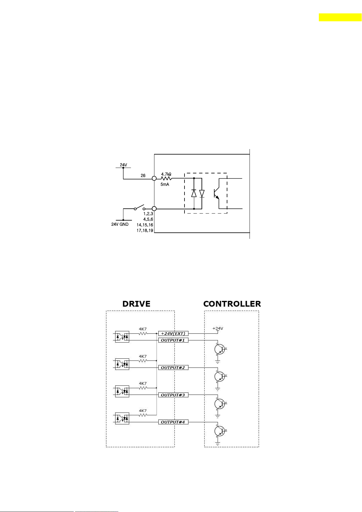
32
8. Control I/O Signal
Drive Internal Circuit
8.2 Connection Circuit
All drive I/O signals are insulated by a photocoupler. The signals display the
internal photocoupler status - [ON: Conduction] and [OFF: Non- Conduction], not the
signal voltage level.
1) Input Circuit
Input circuit power of DC24V±10% (consumed current : about 5mA/circuit) should be
separately prepared.
l Connect NPN type Input signal
Connect the ‘+24V external’signal of drive to ‘+24V’ of Controller .
www.fastech.co.kr
Page 33
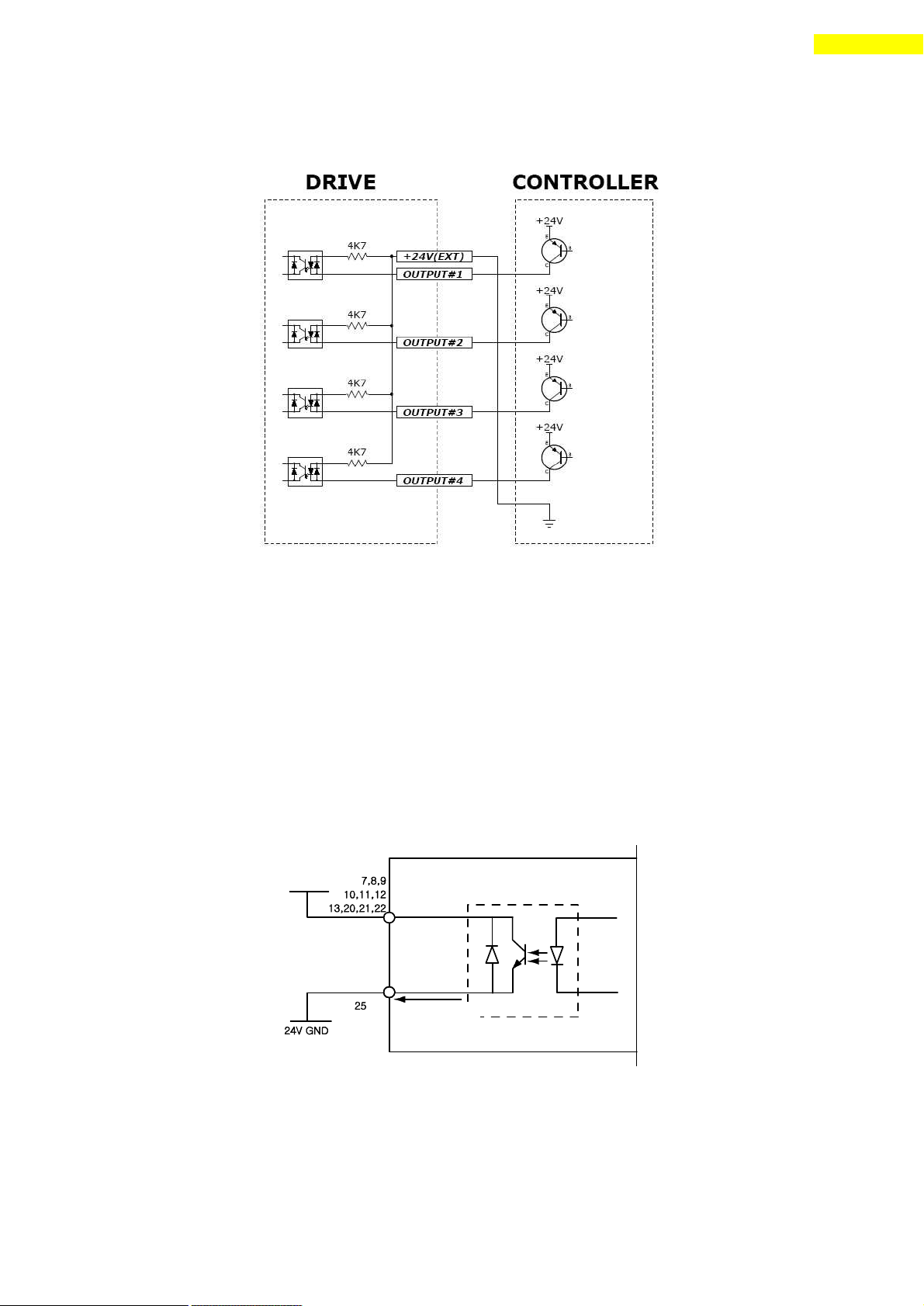
33
8. Control I/O Signal
Drive Internal Circuit
DC 30V
Within 15㎃
Output Port
l Connect PNP type Input signal
Connect the ‘+24V external’signal of drive to ‘GND’ of Controller .
2) Output Circuit
Output circuit power should be separately prepared. This may share input circuit
power. In this case, working power capacity should add output power capacity to
input power capacity.
Applied voltage and power capacity in the control output port are as follows.
·Applied voltage ≤ 30V
·Electrified current ≤ 15mA
www.fastech.co.kr
Page 34
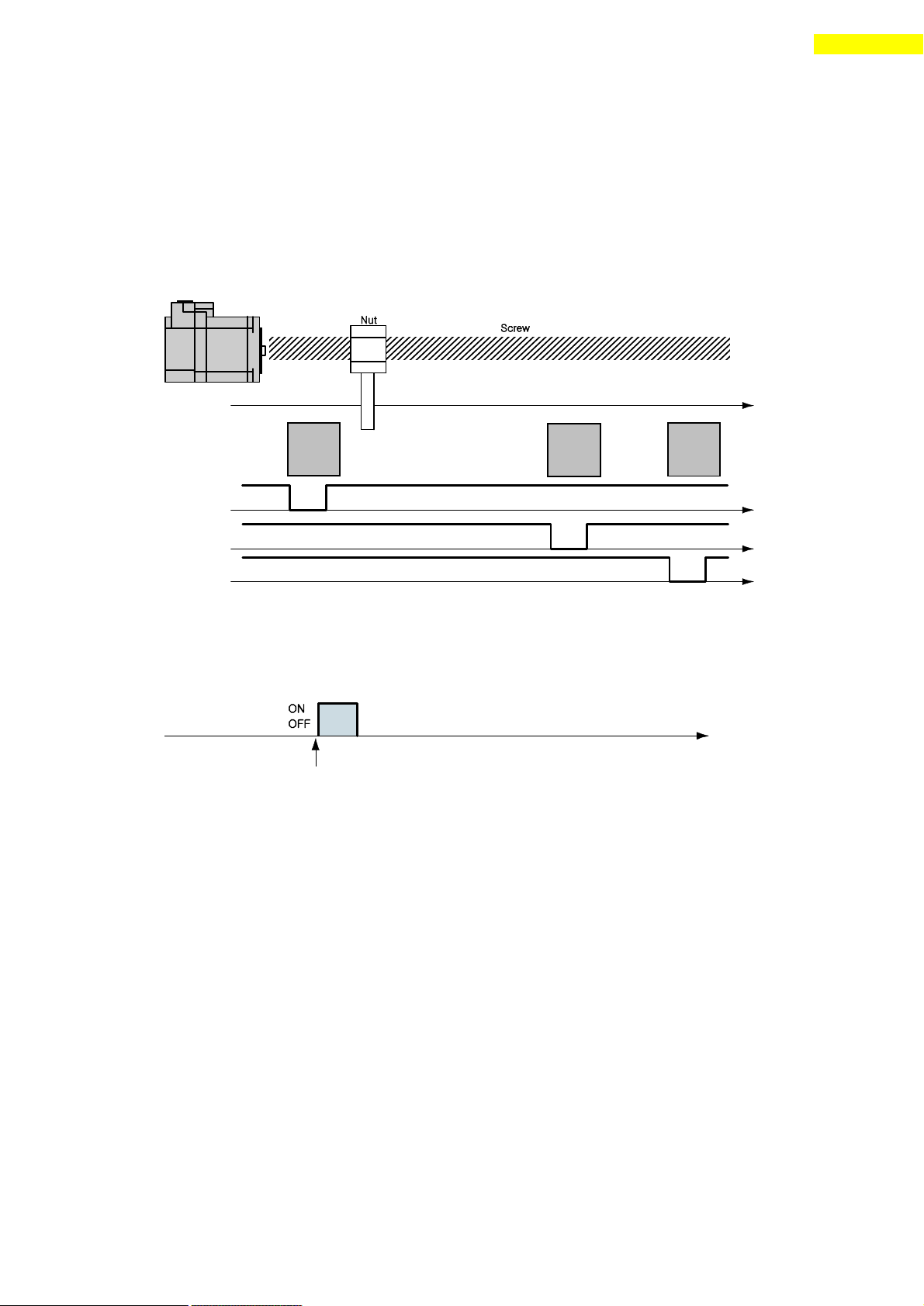
34
8. Control I/O Signal
Limit-
Sensor
Origin
Sensor
Limit+
Sensor
Moving
Limit- Sensor
Limit+ Sensor
Origin Sensor
Reset Input Signal
Set the position to 0 at the rising/falling edge of this
8.3 Input Signal
1) Limit Sensor and Origin Sensor
Limit sensors and origin sensor are assigned to LIMIT+, LIMIT- , and ORIGIN pin in
the CN1 connector respectively. LIMIT+ and LIMIT- sensors are used to limit the
motion of each axis clockwise and counterclockwise to prevent mechanical collision.
Origin sensor is to set the origin of equipment.
2) Clear Pos
This input signal sets the command position and the a ctual position to 0 in
relation to motion position control. The reset signal pulse scale is 10ms or more.
3) Position Table A0 – A7 (PT A0~A7) Input
The position table supports the machine so that its motion can be controlled by
I/O signals of central controller. It can directly transmit commands such as
position table number, start/ stop and origin return to the machine through the PLC.
Also, the user can check output signals such as completion of origin return and
Servo ready through the PLC.
「Position Table A0~A7 」 inputs are total 8 bits of input signal. It is used to
set 256 position table numbers. There are two application methods as follows.
* Ezi-STEP-PR-MI : maximum 64 position table numbers can be set.
1) To set position table number(0 ~255) to be run by ‘PT start’ input signal.
2) To set position table number(0~255) to save current position values by
‘Teaching’ input signal.
By using PT A0~A7 signals, the position table address can be set from 0 to 255
with a binary number. A0 is LSB(least significant bit) and A7 is MSB(most
www.fastech.co.kr
Page 35
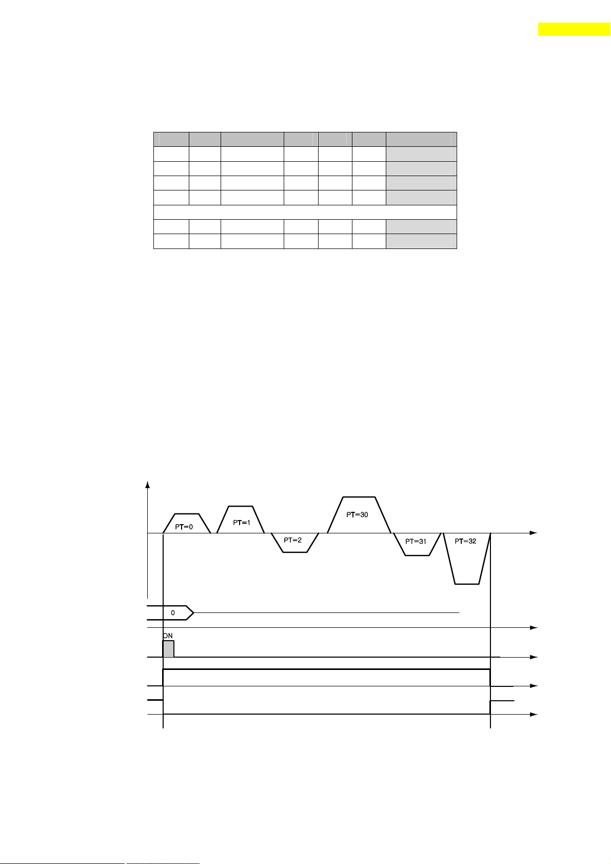
35
8. Control I/O Signal
A7
A6
A5 ~ A3
A2
A1
A0
PT No.
0 0 0
0 0 0
0
0 0 0
0 0 1
1
0 0 0
0 1 0
2
0 0 0
0 1 1
3
… … … … … … … … … … … … … … … … … …
1 1 1
1 1 0
254
1 1 1
1 1 1
255
Motion Pattern
Position Table No. Input (PT A0-A7)
Position Table Start Input Signal (PT Start)
ACK Output Signal
END Output Signal
significant bit). The following table shows how to assign position table number.
*1. Save signal cabling : If ‘PT A0~A7’signal is not connected when motioning by
‘PT Start’signal, the position table number will be ‘0’
4) Position Table Start (PT Start) Input
By using PT A0~A7 signals, set and input the runn ing PT start number. Then the
motion pattern corresponding to the PT No. will be executed.
Following example shows that total 6 motion patter ns are in order executed from
No.0 to No.32 and then stopped.
1) All of PT A0~A7 is set to ‘0’ and PT number is set to ‘0’.
2) Set PT Start signal to [ON], and PT No.0 motion pattern will be executed.
3) When the motion pattern is started by PT, ACK signal and END signal are
displayed to [ON] at CN1 output port as illustrated below. The signal is kept
until one motion pattern loop is stopped. After all motions are stopped, the
output signal level is set to [OFF].
4) PT Start signal is edge trigger and pulse scale is 10ms or more.
*1. Timing of signals : PT A0~A7 signals must be set before (50msec)
PT Start signal set to [ON].
*2. If the PT A0~A7 signals are not used and the PT Start signal set to [ON],
the PT No. 0 will be executed.
www.fastech.co.kr
Page 36
36
8. Control I/O Signal
Motion
Soft Stop Signal
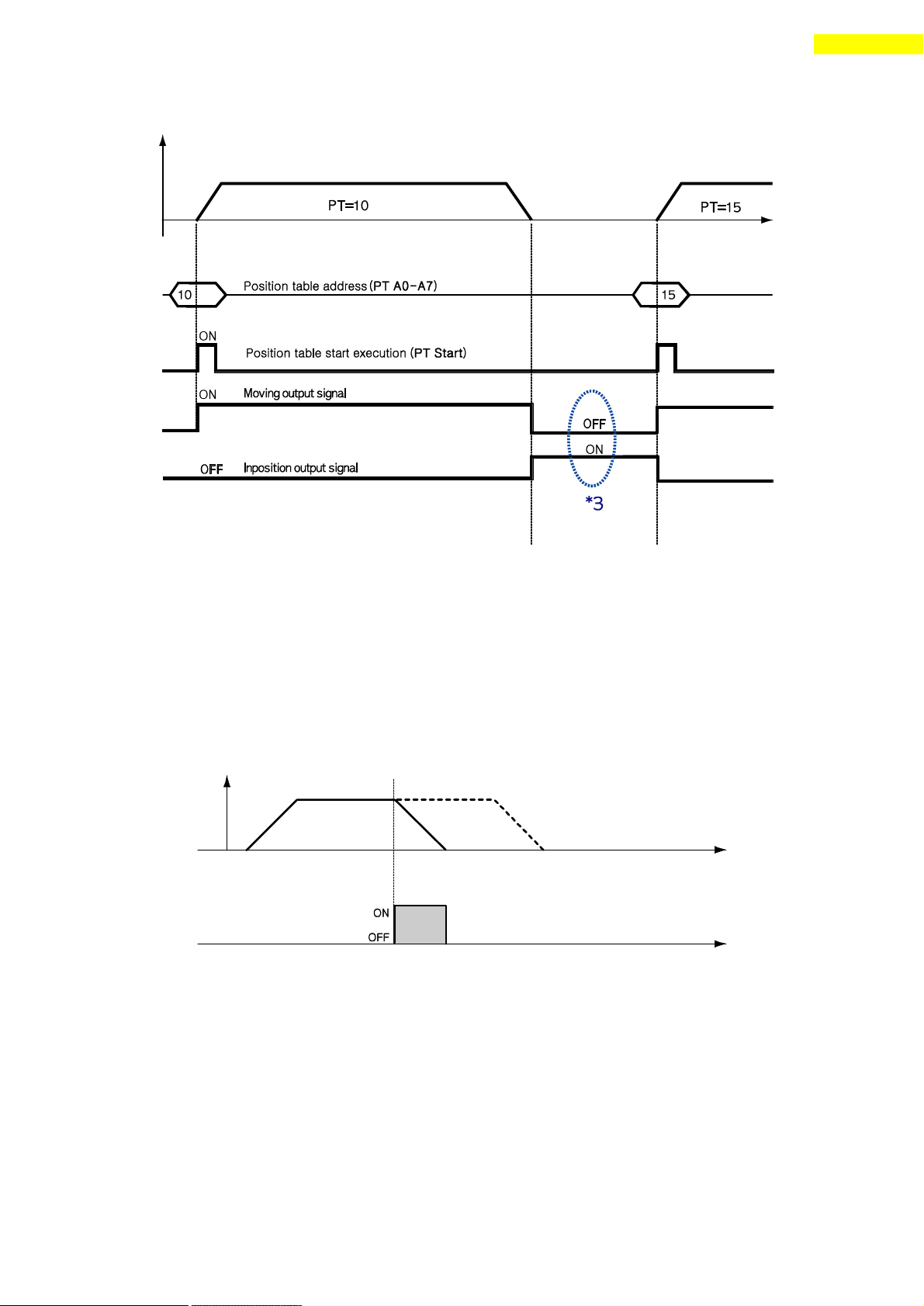
*3. Checking the ‘Moving’ and ‘Inposition’signals :
Between sequencial ‘PT Start’ motion command signal, the checking step
for motion status(Moving, Inposition) is needed before next motion command.
5) Soft Stop Input
Soft stop input signal is to stop motion patter ns under operation. The
deceleration condition until they sto p complies with the deceleration time value
and the start speed value set previously. The soft stop signal is active in ON
level and pulse scale is 10ms or more.
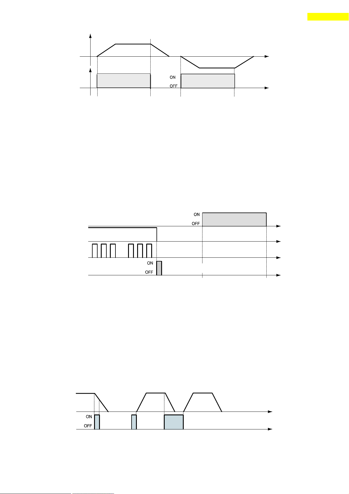
6) Jog+ and Jog- Input
When Jog+ or Jog- signal is ON, the motor r otates clockwise or counterclockwise
until it reaches the hardware limit or the software limit. Jog motion pattern is
subject to jog related parameters (No.7: start speed, No.6: speed, No.8: Acc Dec
time).
www.fastech.co.kr
Page 37
37
8. Control I/O Signal
Plus Direction
Motion Pattern
Minus Direction
Jog- Input
Jog+ Input
Alarm Output
Alarm Blink Output
Alarm Reset Input
(Pulse Scale : 0.1s or more)
Servo Ready Output
STEP ON command
Motion Pattern
Pause Input : A
Pause Input : B
7) AlarmReset Input
When the protective function of drive executes, alarm output is released. When
AlarmReset input is set to ON, alarm output and alarm blink output are released.
Before releasing alarm output, the user must remove any cause of alarm working.
When ‘STEP OFF’button click of ‘Motion Test’ window, the drive stops supplying
the current to the motor and so the user can directly adjust the output position.
When you click ‘STEP ON’, the drive restarts to supply the current to the motor
and its torque is recovered. Befo re operating the motor, the user must set it to
ON.
8) Pause Input
When Pause signal is set to ON, the motion in service is stopped. There are two
pause signal operation modes as follows.
① Case A : When Pause signal is set to ON, the motor starts to decelerate. Pause
② Case B : When Pause signal is set to ON, the motor starts to decelerate. The
Pause signal pulse scale is 10ms or more.
*1. This function is not applied while ‘Repeat Test’ of the User Program(GUI) is
signal becomes OFF before the motor is completely stopped. To start motion,
Pause signal should be set to ON.
signal is continuously main tained since the motor is completely stopped. To
start motion, Pause signal should be set to OFF.
executing.
www.fastech.co.kr
Page 38
38
8. Control I/O Signal
Motion Pattern
PT No. Input A0-A7
Teaching Signal
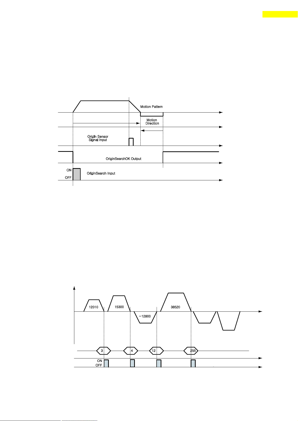
9) Origin Search Input
When ‘Origin Search’ signal is set to ON (10ms or more), it starts to search the
origin position according to selected conditions. The conditions are subject to
parameters such as No. 20:Org Method, No.17:Org Speed, No.18:Org Search Speed,
No.19:Org AccDec Time, No.21:Org Dir. (For more information, refer to
‘12.Parameter’.) When the origin search command is ended, ‘Origin Search OK’
signal is set to ON to CN1 connector ’s output port.
10) Teaching Input
Teaching signal functions that the position value[pulse] being working can be
automatically inputted into a ‘position’ value of a specific position table. If
it is hard to calculate the exact moving distance(position value) of specific
motion mechanically, the user can measure the distance(position value) easily by
using this signal.
1) By using User Program(GUI), set a command type of corresponding PT number
among 4 kinds of absolute moving commands(Absolute Move).
2) By using input signal (PT A0~A7), select corresponding PT number.
3) When Teaching signal is set to ON, the position value[pulse] is save to the
position value of corresponding PT . At this time, it becomes the absolute
position value.
4) Teaching signal pulse scale is 10ms or more.
www.fastech.co.kr
Page 39
39
8. Control I/O Signal
PT No.
Position Value [pulse] of Corresponding PT
3
12010
4
15300
12
-12800
255
38520
Motion Pattern
Emr Stop Input
* After executing Teaching, click ‘Refresh’ icon, and the position value will
* Click ‘Save to ROM’ icon, and the position value will be saved to the ROM
* Teaching signal can be used by two methods; the user assigns actual signal to
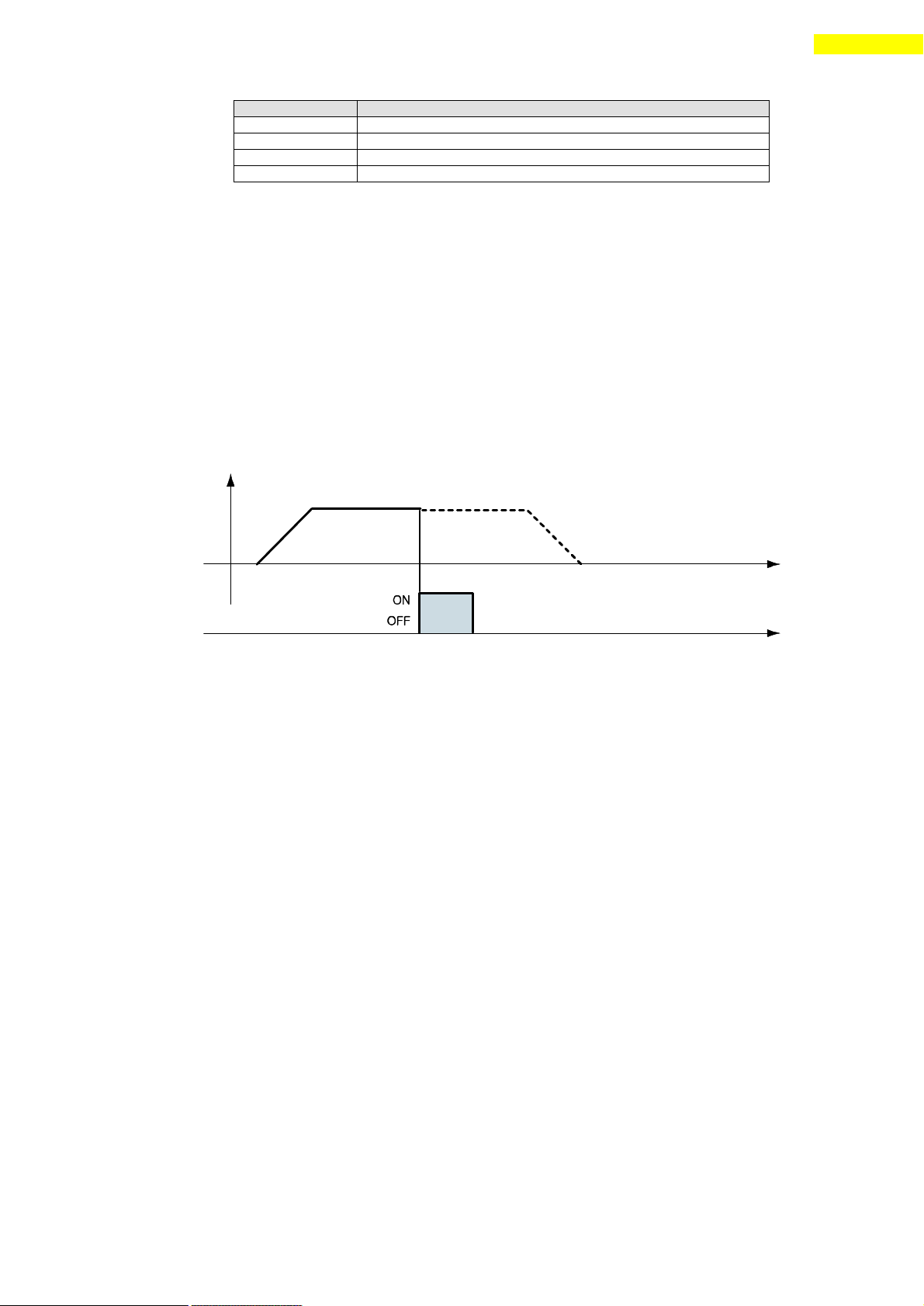
11) E-Stop Input
When ‘Emergency stop ’ signal is set to ON, the current motion is stopped
immediately without deceleration. E -Stop signal is active in ON level and pulse
scale is 10ms or more.
be displayed to the position table.
area.
the motor, or he clicks ‘Teaching’ icon at the ‘I/O Monitoring’ window of
User Program(GUI).
www.fastech.co.kr
Page 40
40
8. Control I/O Signal
PT No.
…
JP Table No.
JPT 0
JPT 1
JPT 2
14 … 15
115
116
225
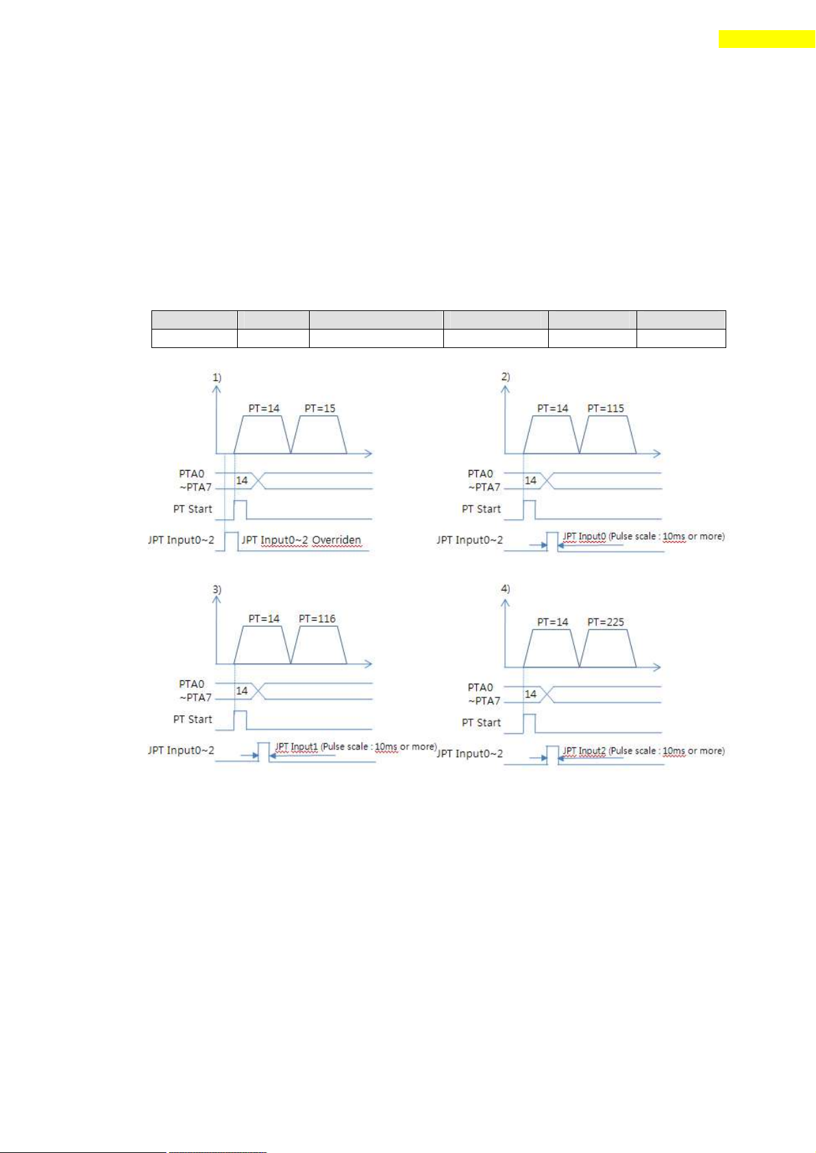
12) JPT Input0~Input2 (Jump Position Table Input) Input
To select motion pattern(position table number) to be subsequently executed
according to input signal conditions.
【 Example 】 If PT 14 motion is operating, when there is no other input signal,
next motion becomes PT 15 as shown in Figure 1). However, if ‘JPT Input0~Input2’
input signal is set to ON while PT 14 is executing, each corresponding position
number is executed as shown in Figure 2)~4).
PT 14 Data
www.fastech.co.kr
Page 41
41
8. Control I/O Signal
PT No.
…
Wait Time
JP Table No
JPT 0
JPT 1
JPT 2
14 … 500
10015
10115
10116
10255
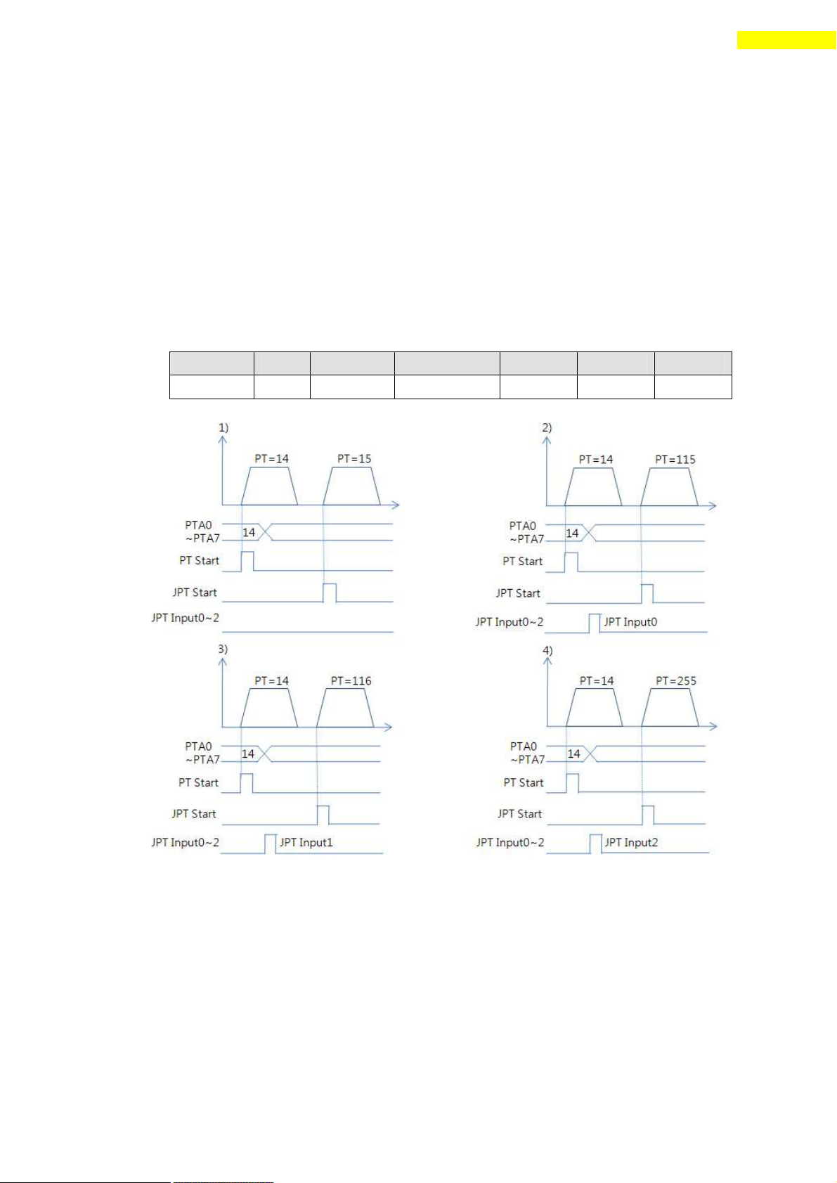
13) JPT(Jump Position Table) Start Input
To select motion pattern(position table number) to be subsequently executed
according to input signal conditions . The difference from Paragraph 「 13) ‘JPT
Input0~Input2 Input」 is:
1) PT number to be jumped must be composed to 10XXX;
2) Next motion is not executed until ‘JPT Start’ is set to ON. If ‘Wait Time’
value of PT data is more than ‘0’, the time lapses additionally and then
next motion is execute d.
【Example】
PT 14 Data
www.fastech.co.kr
Page 42

42
8. Control I/O Signal
Flash
Count
Alarm Name
Condition
1
Over Current
The current through power devices in inverter
exceeds the limit value
2
Over Speed
Motor speed exceed 3000rpm
3
Step Out
Abnormally motor do not followed pulsed input
5
Over Temperature
Inside temperature of drive exceeds 55℃
6
Over Regenerative
voltage
Back-EMF more high limit value*1
7
Motor Connect error
The power is ON without connection of the motor
cable to drive
9
Motor Voltage error
Motor voltage is out of limited value*2
11
System error
Error occurs in drive system
12
ROM error
Error occurs in parameter storage device(ROM)
14
Input voltage error
Power source voltage is out of limited value*3
8.4 Output Signal
1) ‘Compare Out’/ ’Trigger Pulse Output’Output
‘Trigger Pulse Output ’ signal is displayed when specific conditions are
performed. It is fixed to CN1 connector ’s COMP (Compare Out) pin. And it is
available when the motor needs to be sy nchronously controlled by an external
controller. Refer to 「10.5 Trigger Pulse Output」.
2) ‘Alarm’ & ‘AlarmBlink’ Output
When the motor operates normally, alarm output becomes OFF. When the protective
function operates, alarm output becomes ON. The upper controller being used by the
user detects this alarm and then stops motor operation command. If overload or
overcurrent occurs while the motor is ope rating, the drive detects it and cuts off
the motor’s current. And alarm output is set to ON and also ‘AlarmBlink’ flash
so that the user can check abnormality type. The following table shows alarm type
according to flash count.
*1 50V : EzT-NDR-20, EzT-NDR-28, EzT-NDR-42, EzT-NDR-56, EzT-NDR-60
90V : EzT-NDR-86
*2 20V : EzT-NDR-20, EzT-NDR-28, EzT-NDR-42, EzT-NDR-56, EzT-NDR-60
36V : EzT-NDR-86
*3 (Lower limit)
20V : EzT-NDR-20, EzT-NDR-28, EzT-NDR-42, EzT-NDR-56, EzT-NDR-60
36V : EzT-NDR-86
(Upper limit)
28V : EzT-NDR-20, EzT-NDR-28, EzT-NDR-42, EzT-NDR-56, EzT-NDR-60
70V : EzT-NDR-86
www.fastech.co.kr
Page 43
43
8. Control I/O Signal
Motion Pattern
Acc/Dec Signal
Moving Signal
3) ‘PT ACK’ and ‘PT END’ Output
‘ACK’ and ‘END’ signals are available only when the motion is executed by
position table. When ACK signal is set to ON and END signal is set to OFF, all
motion loops are finished. Then ACK signal becomes OFF and END signal becomes ON.
Refer to 「Ezi-STEP Plus-R User Manual – ‘Position Table Function ’」.
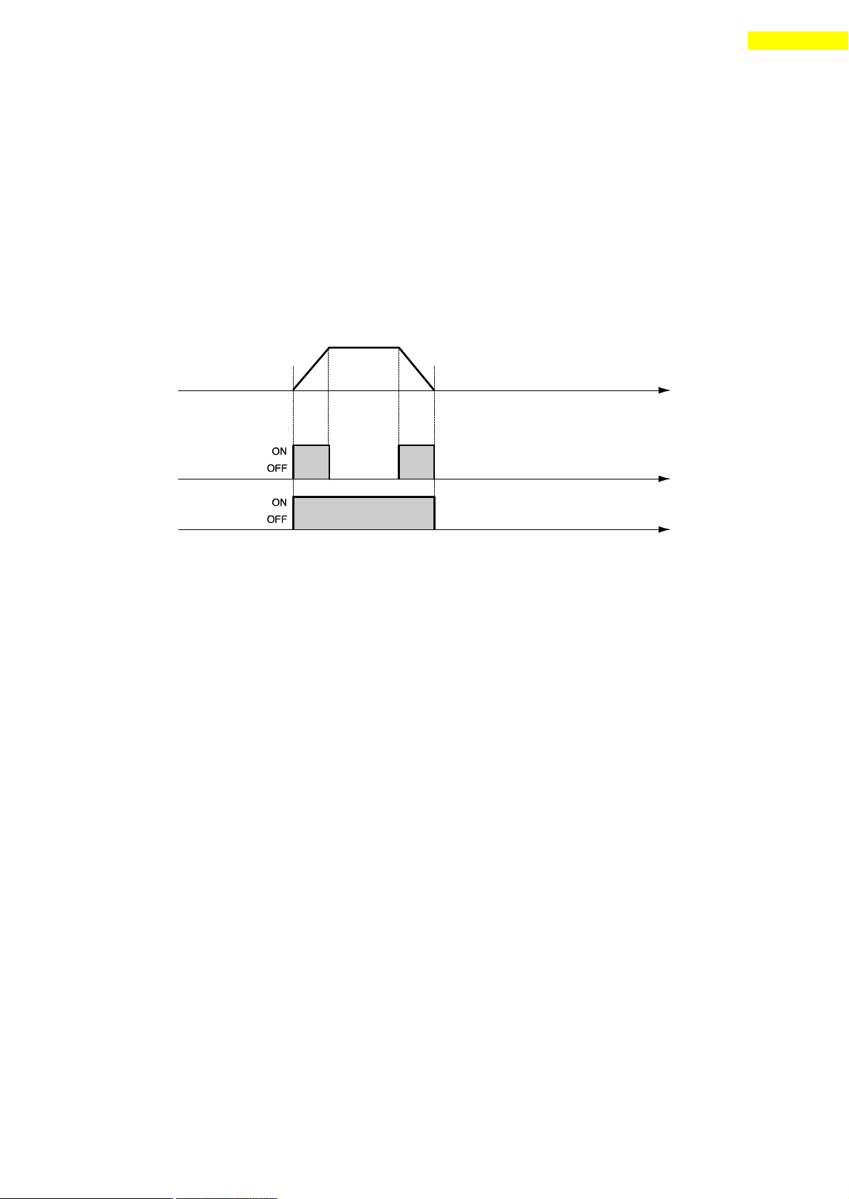
4) ‘Moving’ and ‘Acc/Dec’ Output
As shown below, the position sta rts to move by motion command, and Moving signal
becomes ON and Acc/Dec signal becomes ON in the acceleration and deceleration
section only.
5) ‘Org Search OK’ Output
When the origin return motion is executed by origin search command, ‘Origin
Search OK’ signal is set to OFF. When the origin retu rn motion is normally
finished by the origin sensor, ‘Origin Search OK ’ is set to ON. Refer to 「 7.3
Input Signal - 9) Origin Search Input」.
6) ‘PT(Position Table) Output 0~2 ’ output
Control output used for ‘Start/Stop Message Function ’. When these items are set,
this signal enables the user to check if corresponding PT motion starts or stops
through control output signal. If ‘Start/Stop Message Function ’ is not used,
this signal should be set to 0 or 8. At the position set with other values, the
motion operates as follows.
・ If PT set items are set to ‘1~7’, when the position starts to move, PT
Output HEX value is displayed to ‘PT Output O ~ PT Output 2’.
・ If PT set items are set to ‘9~15’, the position motion is finished and then
PT Output HEX value is displayed to ‘PT Output O ~ PT Output 2’.
For more information, refer to 「 Ezi-STEP Plus-R User Manual – Position Table
Function」.
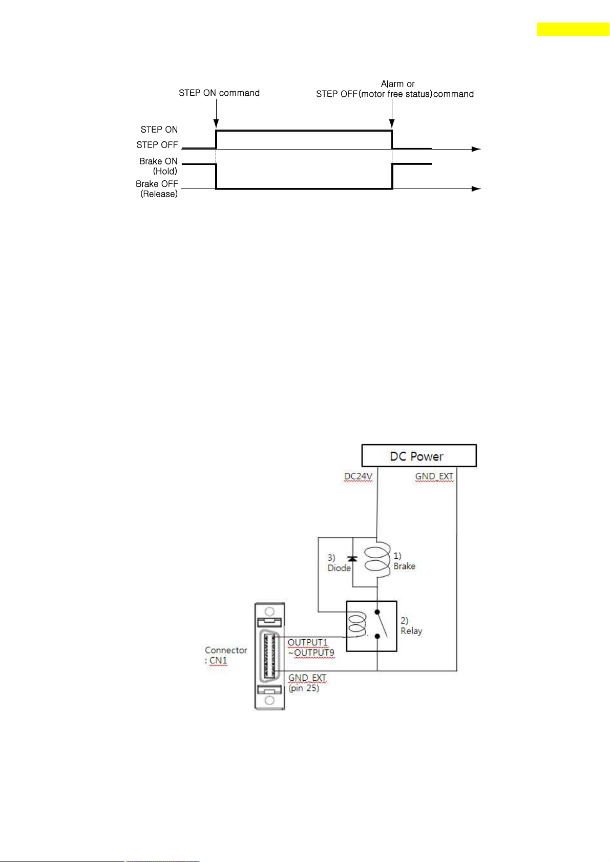
7) ‘BRAKE+’ and ‘BRAKE-‘
This function is used for protect motor rotation in STEP ON status.
DC +24V is connect to ‘BRAKE+’for brake logic and brake control signal
is connect to ‘BRAKE-‘.
It takes some times to supply the current to the motor after STEP ON.
So the Brake signal change to release status after 500[msec] delay.
This function is optional.
www.fastech.co.kr
Page 44
44
8. Control I/O Signal
8) ‘Brake’ Output
This function can be used when the Brake signal is assigned to one of OUTPUT1~
OUTPUT9 of CN1 connector. This is used for protect motor rotation in
Servo ON status. The signal timing diagram between Servo ON command and
Brake signal is same as 7) ‘BRAKE+’ and ‘BRAKE-‘ Output.
This signal used for the Brake that is over 200[mA]/DC24V o f current
consumption. Brake, Relay and diode is needed for this function and the
signal connection diagram is as follows.
*1 Brake : User selected Brake
*2 Relay : under 15[mA] / DC24V
*3 Diode : 1N4004 or equivalent
www.fastech.co.kr
Page 45

45
9. Operation
9. Operation
9.1 Power Supply Timing
Ezi-STEP Plus-R is supplied power through drive module to motor. Therefore, connect
the drive and the motor with a cable and then supply power to the drive module. After
power is supplied, the motor is basically set to STEP ON status.
9.2 STEP ON/OFF Operation
Drive is ‘STEP ON’status after power is supplied.
(1)Click 「STEP OFF」on ‘Motion Test’ window :
It is possible to rotate motor to move initial position by hands. Because
there’s no current supplied to motor (‘motor free’ status).
(2)Click 「STEP ON」on ‘Motion Test’ window :
The motor is prepared to normal motioning by current supply to motor.
‘AlarmReset’command is used for this function through DLL program.
9.3 Operation Mode
This controller can do three control operations such as I/O command, communication
command(DLL program), and User Program(GUI)
(1) I/O Command Mode
This controller can execute control operation like in-position by I/O command
transmitted from the upper controller. The in-position control operation is
executed by operating position table with I/O command.
(2) Communication Command Mode
This controller can execute control operation like in -position by command
transmitted from the upper controller. The in -position control operation is
executed by operating position table with I/O command
Position Table Operation Sequence
In case of Ezi-STEP Plus-R, the system can execute continuous operation by
position table at the I/O command mode.
① By using PT A0 ~ PT A7 input signal or DLL program, set PT number to be
operated.
② In case of Servo OFF, set the controller to Servo ON by communication program
or Servo ON control input.
③ Start to operate by rising edge of PT Start input signal or communication
program.
Stopping Continuous Operation of Position Table
When the motor is executing continuous operation of position table with Ezi-STEP
www.fastech.co.kr
Page 46

46
9. Operation
Parameter Name
Setting Content
Range
Axis Max Speed
Operation speed after acceleration is finished
1~500,000[pps]
Axis Start Speed
Operation start speed before acceleration starts
1~35,000[pps]
Axis Acc Time
Required time until the motor reaches the axis max
speed from stop status
1~9,999[ms]
Axis Dec Time
Required time until the motor reaches from the axis
max speed to the stop status
1~9,999[ms]
Motion Dir
To select motion direction (CW or CCW)
0~1
Pulse per
Revolution
Number of pulses per revolution.
The range of ‘Axis Max Speed’parameter is depend
on this value.
0~15
Plus-R, stop executing position table by following methods.
① To use DLL program or control input signal corresponding to ‘Stop’ and ‘E-
Stop’. In this case, operation is completely finished and is not connected to
next operation.
② The user can click 「 Pause 」 at User Program(GUI) to temporarily stop
operating. In this case, click 「 Pause 」 again, and remaining operation will
be executed again.
Speed Control Operation
To operate the motor by parameters set by User Program(GUI) or DLL program. (This
is not connected with PT operation.)
Once speed control operation is started, PT operation command is overridden.
Likewise, while PT operation is executing, speed control operation command is
overridden.
The followings show parameters applied to speed control op eration. All position
table item values are overridden.
Teaching Function
Teaching can be executed only by User Program(GUI). For more information, refer to
「User Manual – Position Table Function」.
www.fastech.co.kr
Page 47
47
10. Other Operation Functions
PT
No.
Command
type
Position
Low
Speed
High
Speed
Accel.
time
Decel.
time
Wait
time
Continuous
Action
JP Table
No.
0 3 10000
1
2500
50
300 0 1
1
1 3 1000
1
500 - - 0 1
2
2 3 5000
1
1500
50
300
300 0 3
3 3 -2500
1
1000
300
300 0 0
-
No.
Parameter Name
Setting Value
Unit
6
Jog Speed
1500
[pps]
7
Jog Start Speed
100
[pps]
8
Jog Acc Dec Time
200
[msec]
Jog+
Command
Jog-
Command
10. Other Operation Functions
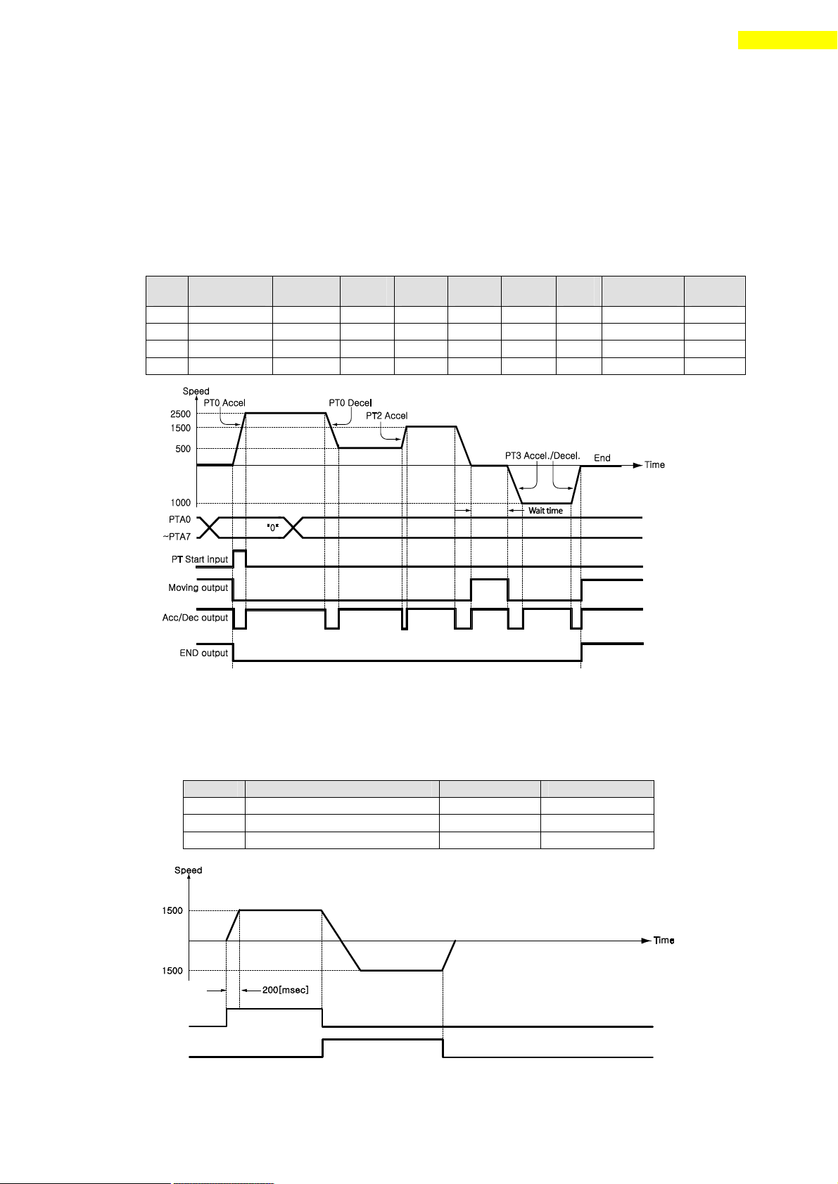
10.1 Position Table(PT) Operation Example
Input ‘PT A0~ PT A7’ signals to set PT number. Input ‘PT Start’number to execute
speed control operation. For more information, refer to 「User Manual – Position Table
Function」.
【Position Table Setting】
10.2 Jog Operation Example
The machine executes speed control operation at the speed set by parameters according to
inputting ‘Jog+’ and ‘Jog-‘ signals.
【Parameter Setting】
www.fastech.co.kr
Page 48
48
10. Other Operation Functions
Parameter Name
Description
Range
Org Speed
Operation speed when origin return starts
1~500,000[pps]
Org Search Speed
Low-speed operation speed after origin sensor is
sensed and operation start speed when origin start.
1~50,000[pps]
Org Acc Dec Time
The time assigned to the acceleration/deceleration
section when origin return starts and sto ps.
1~9,999[ms]
Org Method
To select how to return the origin
0~2
Org Dir
To select operation direction(CW or CCW)
0~1
Org Offset
After origin return is finished, the motor moves
additionally as this setting value and then stops.
-134,217,727 ~
134,217,727
Org Position Set
After origin return is finished, ‘Command Pos’ value
is set to this setting value.
-134,217,727 ~
134,2177,27
Org Sensor Logic
To set the origin sensor signal level.
0~1
Origin Search Command
Origin Sensor Signal Input
Origin Search OK Signal Output
10.3 Origin Return
If the machine is operated by I/O signals, the motor can execute origin return by
inputting ‘Origin Search’ signal. Also, the motor can execute origin return with
User Program(GUI) and DLL program. The following table shows parameter types related
to origin return.
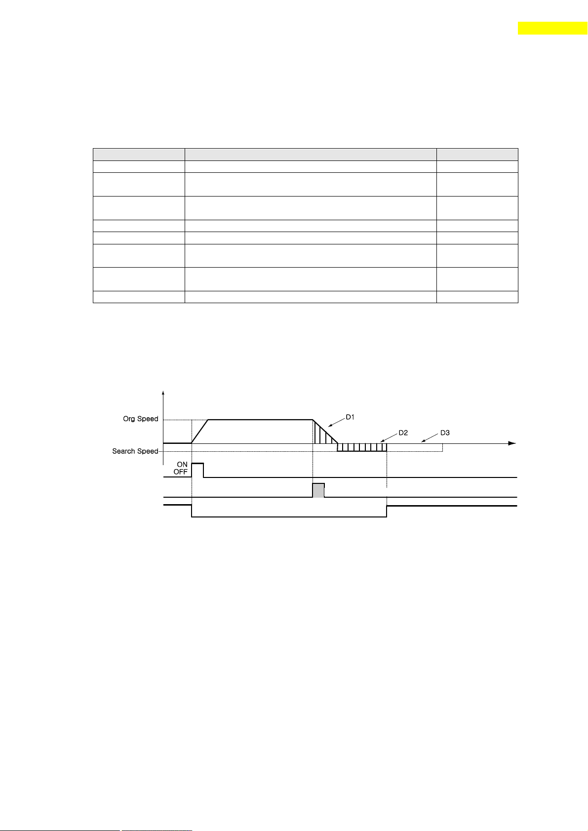
(1) Origin Return Method Setting
To execute origin return, ‘Org Method’ parameter should be set as follows.
① Common Origin (In case of ‘Org Method’= 0)
The machine moves up to the origin sensor by ‘Org Speed’ and ‘Org Acc Dec
Time’ parameters and then finishes precise origin return at the low speed set
to ‘Org Search Speed’. The machine senses the origin sensor and moves as far
as D1 and then stops. And the machine changes its moving direction and
additionally moves as far as D 2 and then stops. D1 and D2 are the same moving
distance. If Org Offset parameter is not ‘0’, the machine moves additionally
as much as the parameter (ex: D3) and then stops. If the limit sensor is sensed
while the machine is under origin return, the machine stops and reverses its
moving direction and then continu es to origin return operation.
www.fastech.co.kr
Page 49
49
10. Other Operation Functions
Origin Search OK Output
Origin Sensor Signal
Origin Return Command
Z Pulse
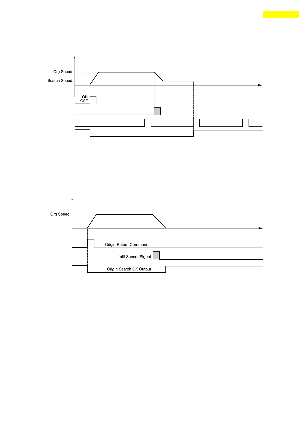
② Z-pulse Origin (In case of ‘Org Method’= 1)
This method can be used when external encoder is connected.
The machine moves up to the origin sensor by ‘Org Speed’ and ‘Org Acc Dec
Time’ parameters and then finishes Z-pulse origin return at the low speed set
to ‘Org Search Speed’. That is, after the origin sensor is sensed, the machine
moves slowly to the original moving direction until Z -pulse signal is sensed.
③ Limit Origin (In case of ‘Org Method’= 2)
The machine moves up to the spot which the limit sensor is sensed by ‘Org
Speed’ parameter, and stops by ‘Org Acc Dec Time ’value. The moving direction
complies with as set in ‘Org Dir’.
If there’s no limit sensor on your system, you can set ‘Origin’ by ‘S/W
Limit Plus Value’ and ‘S/W Limit Minus Value’of parameters.
(2) Origin Return Procedure
Origin return is executed to the following procedure.
j Set parameters required to origin return.
k Start origin return operation to the r ising edge of control input origin
search or the communication program.
www.fastech.co.kr
Page 50

50
10. Other Operation Functions
Setting Item
Description
Range
Start/Stop
Setting start/stop of pulse output
0~1
Pulse Start
Position
Setting the start position of first
pulse output
-134,217,727 ~
134,217,727
Pulse Period
Setting the pulse period.
( 0 : pulse output only 1 time in
Pulse start position.
1~ : pulse output repeatedly
depends on setting.)
0~134,217,727
[pulse]
Pulse Width
Setting the pulse width
1~1000[ms]
(3) Interruption of Origin Return
When the machine is under origin return, click ‘Stop’ or ‘E-Stop’ to stop the
machine. In this case, the machine ’s origin is not edited and origin return is
not finished either.
(4) Output of Origin Return Finish
The completion of origin return operation can be decided with related bit values
of either ‘Origin Search OK ’ of control output or ‘Axis Status’ of
communication program.
10.4 Stop Operating
By using two methods of control input and communication program command, the user can
input stop and emergency stop commands. Even though the emergency stop command is
inputted, the motor will not ‘STEP OFF’(‘motor free’ status). In case emergency
stop, the machine stops immediately without deceleration. So, a special caution for
mechanical impact is required.
10.5 Trigger Pulse Output
This function is used when the output signal becomes ON periodicallyin in specific
condition. External encoder is needed for this function.
(1) Setting
This function is working with RS -485 communication (DLL library) method.
This command can be executed during the positioning command or before the positioning
command also. The following table shows the setting conditi ons and refer to
「User Manual – Communication Function」.
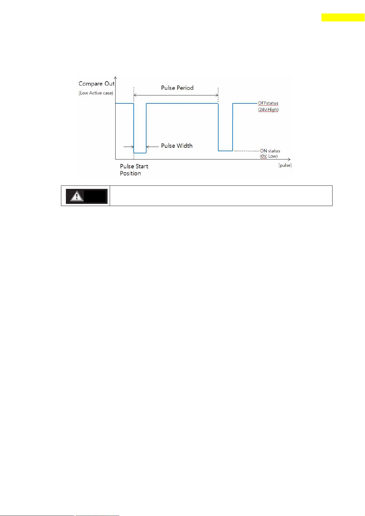
(2) Signal Output
This output pin of CN1 connector for Trigger Pulse is fixed to 「Compare Out」and
the signal disgram is as follows.
www.fastech.co.kr
Page 51
51
10. Other Operation Functions
The pulse is output only in bigger position area than ‘pulse start
position’and is output in both motion direction.
Caution
(3) Status Check
By using DLL program, the user can check the trig ger pulse output status.
Refer to 「User Manual – Communication Function」.
www.fastech.co.kr
Page 52
52
11. Communication Function
If Windows goes to the stand -by mode, serial communication is
basically disconnected. So, after recovering from the stand -by mode,
the user should connect communication again. This content is equally
applied to the library provided with the product.
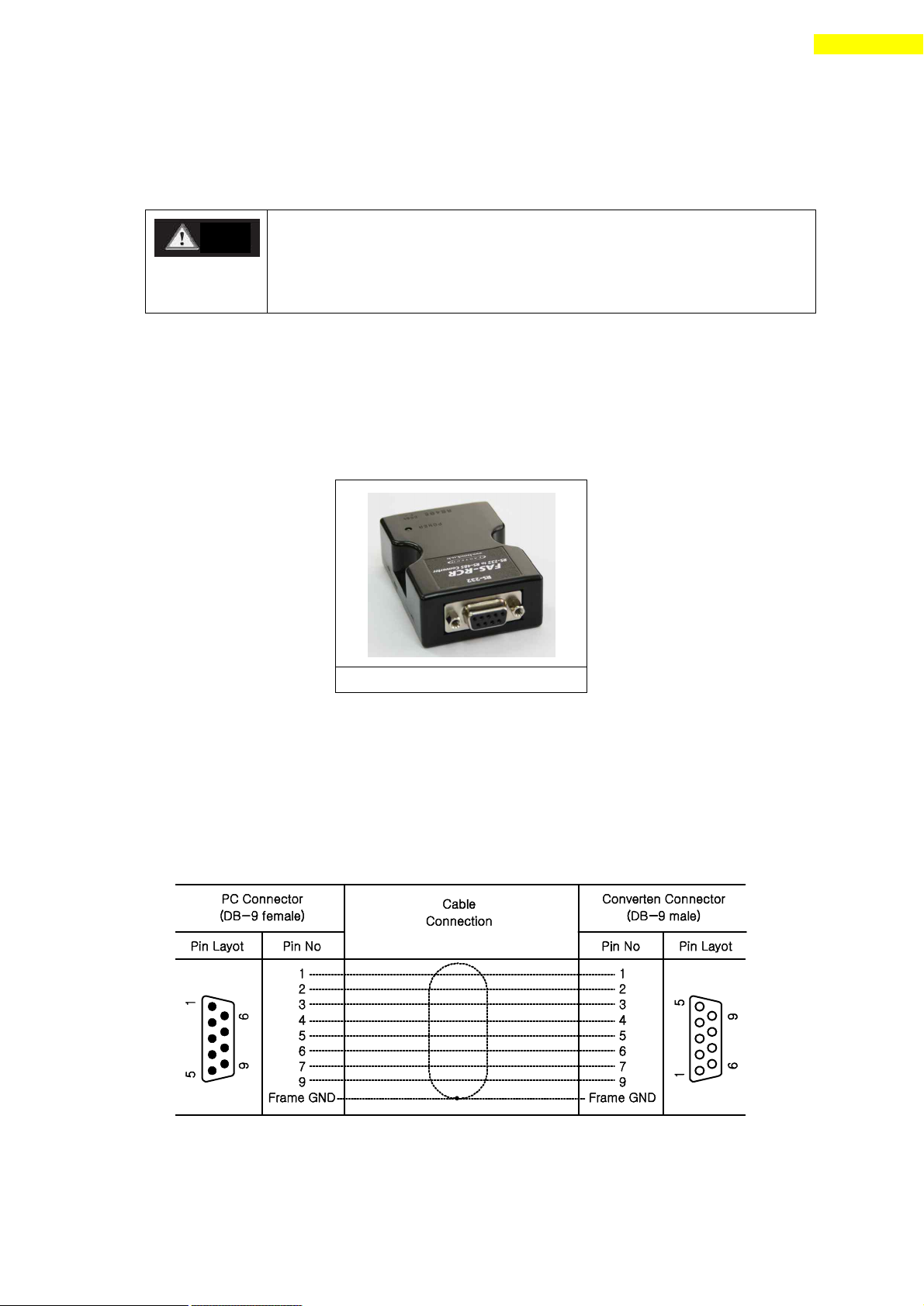
RS-485 Converter (to RS-232)
Caution
11. Communication Function
In case of RS-485, up to 16 axes can be controlled by the multi -drop link(daisy chain).
11.1 Connection with the PC
There are one method of connecting the drive and the PC by RS-485(serial
communication). PC’s RS-232C port is used. By using following communication
converters according to each communication type, the user can connect the PC and the
drive module. The maximum communication speed i s 115200[bps] with RS -232 to RS-485
converter.
For connection with the PC, refer to 「5.2 Controller Configuration」.
1) Cable of Connecting RS232 Port (to PC) and Converter (RS232 ↔ RS-485)
Normally Power does not need to be supplied to the converter module. But when
the communication have problems without power, DC 5~24V external power can connect.
The signal is wired as follows.
www.fastech.co.kr
Page 53
53
11. Communication Function
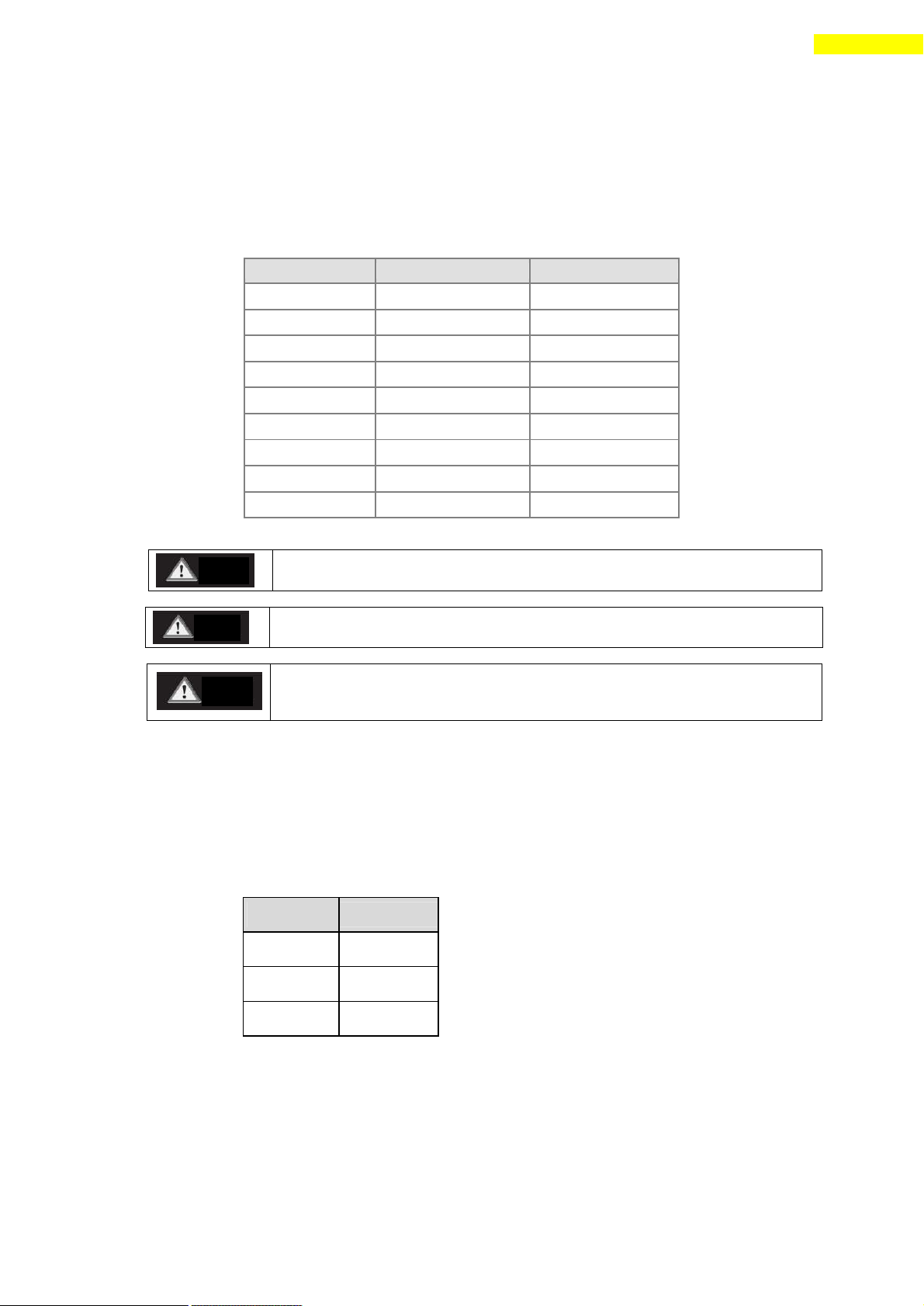
RJ45 Pin No.
UTP CAT5E cable
Function
1
White/Orange
GND
2
Orange
GND
3
White/Green
Data+
4
Blue
GND
5
White/Blue
GND
6
Green
Data-
7
White/Brown
GND
8
Brown
GND
case
Frame GND
The cable length of RS-485 Converter<->Drive or Drive<->Drive must be
longer than 60 cm.
Signal cable ‘Data+’ and ‘Data-’ are differential type signals.
These two signal cables must be twisted.
The connector fixed pin is connected to Frame GND through the mount
hall of the PCB. At this time, it is recommended to use STP CAT5E
cable.
Pin No.
Function
1
Data+
2
Data-
3
GND
Cautio
Caution
Caution
2) Cable of connecting RS-485 Converter and Drive Module(CN5: Ezi-STEP-PR only)
Connector Type : RJ45
Cable Type : LAN cable, CAT5 or better (UTP or STP)
Signal Wiring : Standard Straight Wiring
(1↔1, 2↔2, 3↔3,…, 8↔8)
If multi-axis connection is required at one segment, up to 16 drive modules can be
connected by the daisy -chain method. The pin signal content is as follows.
3) Cable of connecting RS-485 Converter and Drive Module(CN5 : Ezi-STEP-PR-MI only)
Signal Wiring : Standard Straight Wiring
(1↔1, 2↔2, 3↔3)
If multi-axis connection is required at one segment, up to 16 drive modules can be
connected by the daisy -chain method. The pin signal content is as follows.
www.fastech.co.kr
Page 54

54
11. Communication Function
Terminal
Resistance
Internal Circuit
Drive
11.2 Communication Interface Circuit
The above figure shows an I/O circuit of RS485 communication interface signal. When
communication is connected, Ezi-STEP Plus-R maintains the receive stand-by status. It
performs sending only when it receives the signal from upper communication and then
replies. For more information about communication function, refer to 「 User Manual –
Communication Function 」 in a separate volume.
www.fastech.co.kr
Page 55
55
12. Protective Function
Flash
Count
Alarm Name
Condition
1
Over Current
The current through power devices in inverter
exceeds the limit value
2
Over Speed
Motor speed exceed 3000rpm
3
Step Out
Abnormally motor do not followed pulsed input
5
Over Temperature
Inside temperature of drive exceeds 55℃
6
Over Regenerative
voltage
Back-EMF more high limit value*1
7
Motor Connect error
The power is ON without connection of the motor
cable to drive
9
Motor Voltage error
Motor voltage is out of limited value*2
11
System error
Error occurs in drive system
12
ROM error
Error occurs in parameter storage device(ROM)
14
Input voltage error
Power source voltage is out of limited value*3
12. Protective Function
12.1 Alarm Type
When an alarm occurs while the controller is operating, a red LED among status display
LEDs flash and the following protective function will be display ed according to flash
count.
12.2 Acquiring Alarm Information
When an alarm occurs, the motor become S TEP OFF(motor free) and then stops by free run
and at the same time displays alarm message.
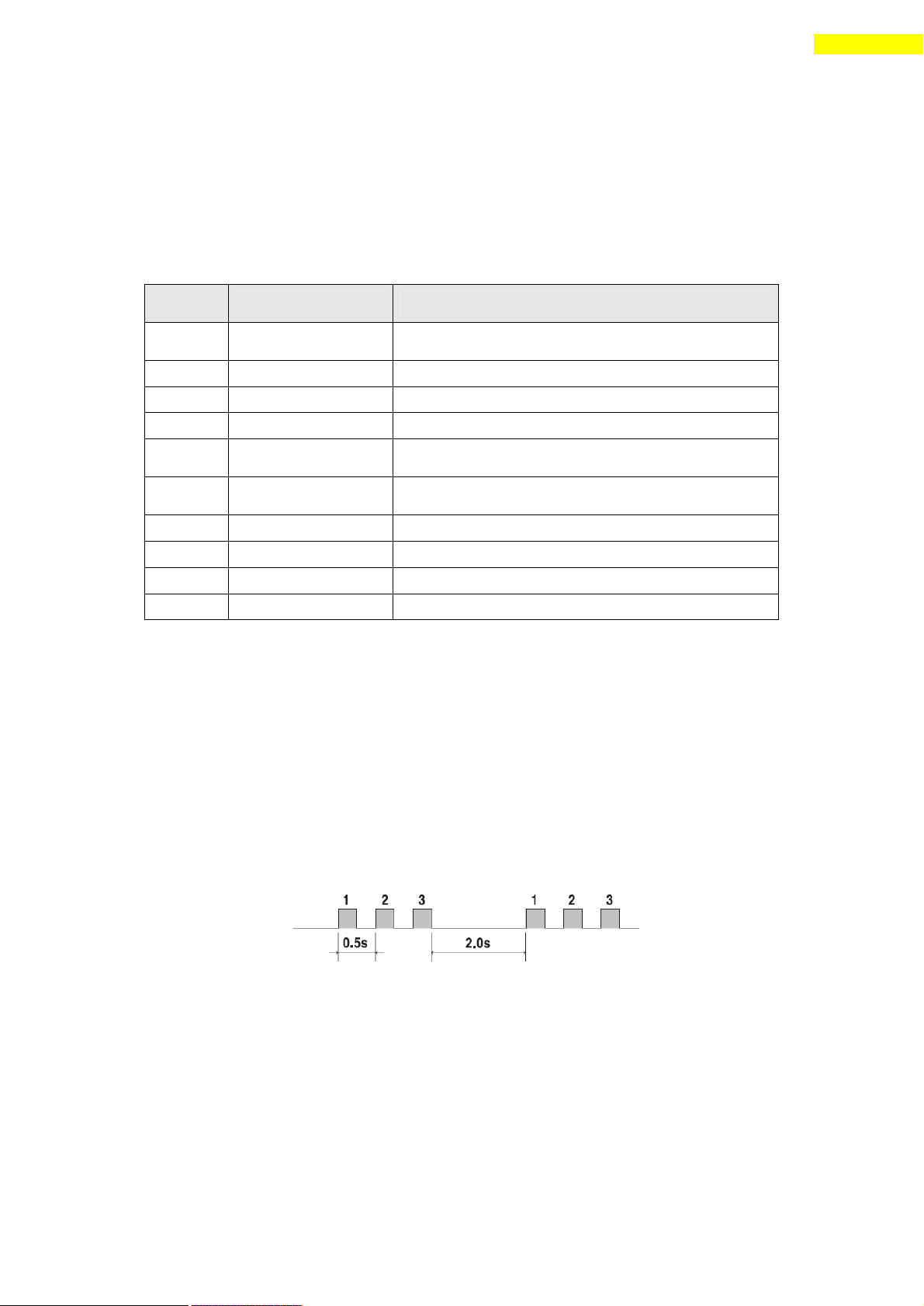
Also, ‘AlarmBlink’ signal repeats On/Off according to the timing as illustrated
below. The red LED flash every 0.5 second in accordance with alarm number and wait for
2 seconds. And then red LED flash repeatedly until inputting ‘AlarmReset’signal.
(Example) Alarm 3: ‘AlarmBlink’display signal occurred when the Stall is occur.
www.fastech.co.kr
Page 56

56
12. Protective Function
Flash
Count
Alarm Name
Description
Reset
1
Over Current
Check the mechanical status such as parameter setting,
motor’s short-circuit, or machine load (whether
machine edge is collided), etc.
Valid
2
Over Speed
Check parameter setting, and abnormal operation of the
motor.
Valid
3
Step Out
Get down the load or increase the acceleration or
deceleration speed.
Valid
5
Over
Temperature
Get down the ambient temperature or install a cooling
fan.
Valid
6
Over
Regenerative
voltage
In case of high-speed operation, check if the
acceleration or deceleration speed is low.
Valid
7
Motor Connect
error
Check the connection status of drive and motor.
Invalid
9
Motor Voltage
error
Check if power is supplied to the drive.
Invalid
11
System error
Check the green LED of CN5.
Invalid
12
ROM error
Check the green LED of CN5.
Invalid
14
Input voltage
error
Check if power is supplied to the drive.
Invalid
12.3 Alarm Reset
If an alarm occurs, remove its cause and then release it. The alarm can be released as
follows. In case of alarms of which ‘Reset’column is indicated to ‘Invalid’, power
must get downed prior to releasing the alarms.
www.fastech.co.kr
Page 57

57
13. Parameter
No.
Name
Unit
Lower Limit
Upper Limit
Default
0
Pulse per Revolution
0 15
10
1
Axis Max Speed
[pps] 1 500,000
500,000
2
Axis Start Speed
[pps] 1 35,000
1
3
Axis Acc Time
[msec] 1 9,999
100
4
Axis Dec Time
[msec] 1 9999
100
5
Speed Override
[%] 1 500
100
6
Jog Speed
[pps] 1 500,000
5,000
7
Jog Start Speed
[pps] 1 35,000
1
8
Jog Acc Dec Time
[msec] 1 9,999
100
9
Servo Alarm Logic
0 1
0
10
Servo On Logic
0 1
0
11
Servo Alarm Reset Logic
0 1
0
12
S/W Limit Plus Value
[pulse]
-134,217,727
+134,217,727
+134,217,727
13
S/W Limit Minus Value
[pulse]
-134,217,727
+134,217,727
-134,217,727
14
S/W Limit Stop Method
0 1
1
15
H/W Limit Stop Method
0 1
1
16
Limit Sensor Logic
0 1
0
17
Org Speed
[pps] 1 500,000
5,000
18
Org Search Speed
[pps] 1 500,000
1,000
19
Org Acc Dec Time
[msec] 1 9,999
50
20
Org Method 0 2 0
21
Org Dir 0 1 0
22
Org Offset
[pulse]
-134,217,727
+134,217,727
0
23
Org Position Set
[pulse]
-134,217,727
+134,217,727
0
24
Org Sensor Logic
0 1
0
25
Stop current
[%]
10
100
50
26
Motion Dir 0 1 0
27
Limit Sensor Dir
0 1
0
28
Encoder Multiply Value
0 3
0
29
Encoder Dir
0 1
0
30
Pos. Value Counting Method
0 1
0
13. Parameter
13.1 Parameter List
13.2 External Encoder Connection
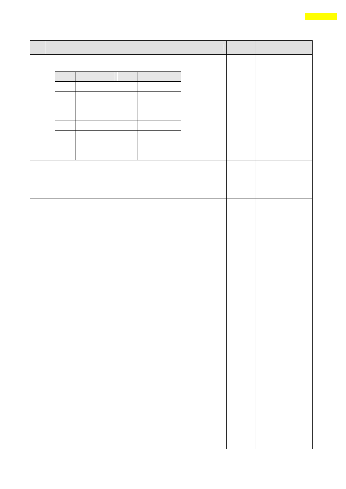
When external encoder is conne cted to Ezi-STEP PlusR, the user have to set correct
parameters for specification of encoder.
‘No.0 (Pulse per Revolution)’: resolution value that include the multiply value.
‘No.28 (Encoder Multiply Value) ’: encoder multiply value
www.fastech.co.kr
Page 58
58
13. Parameter
No.
Description
Unit
Lower
Limit
Upper
Limit
Default
0
Pulse per Revolution :
Number of pulses per revolution.
Vaule
ppr
Vaule
ppr
0
500 8 6400
1
1000 9 8000
2
1600
10
10000
3
2000
11
20000
4
3200
12
25000
5
3600
13
36000
6
4000
14
40000
7
5000
15
50000
0
15
10
1
Axis Max Speed :
When position moving commands (absolute move, incremental move) are
given, this mode sets the maximum speed which the motor can
operate. So, the motor cannot be operated faster than this value
in any case. This value is set to [pps] unit.
pps 1 500,000
500,000
2
Axis Start Speed :
When position moving commands (absolute move, incremental move) are
given, this mode sets the operation start speed to [pps] unit.
pps 1 35,000
1
3
Axis Acc Time :
When position moving commands (absolute move, incremental move) are
given, this mode sets the acceleration section of operation start
segment to [msec] unit.
Possible range is different from Axis Speed.
(Ex.1) Axis Start Speed=1, Move Speed=400000 : 1~1430 [msec]
(Ex.2) Axis Start Speed=1, Move Speed=10000 : 1~350 [msec]
msec 1 9,999
100
4
Axis Dec Time :
When position moving commands (absolute move, incremental move) are
given, this mode sets the deceleration sect ion of operation stop
segment to [msec] unit.
Possible range is different from Axis Speed same as ‘Axis Acc
Time’parameter
msec 1 9,999
100
5
Speed Override :
When position moving commands (absolute move, incremental move) are
given, the operation speed i s subject to the ratio set to ‘Move
Speed’. (Ex) If current move speed is 10,000 and speed override
is 200, actual motion speed is set to 20,000.
% 1 500
100
6
Jog Speed :
When jog position moving command is given, this mode sets the
motor revolution valu e to [pps] unit.
pps 1 500,000
5000
7
Jog Start Speed :
When jog position moving command is given, this mode sets the
operation start speed to [pps] unit.
pps 1 35,000
1
8
Jog Acc Dec Time :
In case of jog operation, this mode sets the time of acceleration
and deceleration sections to [msec] unit.
msec 1 9,999
100
9
Alarm Logic :
When the motor or the drive is defective and so alarm signal
output is ON through CN1 connector, this mode sets the output
signal level.
♦ 0 : 0 V (Active low level)
♦ 1 : 24V (Active high level)
0 1
0
13.3 Parameter Description
www.fastech.co.kr
Page 59

59
13. Parameter
10
Run/Stop Logic:
When the motor is run, this signal output is ON through CN1
connector, this mode sets the output signal level.
♦ 0 : When motor is run, 0 V (low level) is outputted.
♦ 1 : When motor is run, 24V(high level) is outputted.
0 1 0
11
Alarm Reset Logic :
When the motor or the drive is defective and so an alarm occurs,
this mode sets the input signal level to release the alarm signal.
Before releasing the alarm signal, the user must release its
cause.
♦ 0 : 0 V (Active low level)
♦ 1 : 24V(Active high level)
0 1 0
12
S/W Limit Plus Value :
When position moving commands (absolute move, incremental move ,
jog) are given, this move set the maximum input limit that the
motor can move to the plus(+) direction with 28 bits.
When this value set to ‘0’, S/W Limit function is canceled
pulse
-134,217,
727
+134,217,
727
+134,217,
727
13
S/W Limit Minus Value :
When position moving commands (absolute move, incremental move ,
jog) are given, this move set the minimum input limit that the
motor can move to the minus(-) direction with 28 bits..
When this value set to ‘0’, S/W Limit function is canceled
pulse
-134,217,
727
+134,217,
727
-134,217,
727
14
S/W Limit Stop Method :
Sets how to stop the motor by SW Limit Plus/Minus Val ue’, not
stop motion by the limit sensor.
♦ 0 : stops the motor immediately by e mergency stop mode.
♦ 1 : stops the motor gradually by soft stop mode.
0 1
1
15
H/W Limit Stop Method:
In case of stop motion by the limit sensor, this mode sets how to
stop the motor.
♦ 0 : stops the motor immediately by e mergency stop mode.
♦ 1 : stops the motor gradually by s oft stop mode.
0 1
1
16
Limit Sensor Logic :
Sets the signal level so that the motor can recognize limit
sensor’s input to ON.
♦ 0 : 0 V (Active low level)
♦ 1 : 24V(Active high level)
0 1
0
17
Org Speed :
In case of origin return command, this modes sets the operation
speed until the motor senses the origin sensor to [pps] unit.
pps 1 500,000
5,000
18
Org Search Speed :
In case of origin return command, The low operation speed for
precise origin return after the motor senses the origin sensor is
set to [pps] unit by this mode.
pps 1 500,000
1,000
19
Org Acc Dec Time :
In case of origin return command, the acceleration/deceleration
section time of the operation start/stop segment is set to [msec]
unit by this mode.
msec 1 9,999
50
www.fastech.co.kr
Page 60

60
13. Parameter
20
Org Method :
The user can select origin return command types.
♦ 0 : The motor moves up to the origin sensor spot by ‘Org
Speed’ and then executes precise origin return at the low
value of ‘Org Search Speed’.
♦ 1 : The motor moves up to the origin sensor spot by ‘Org
Speed’ and then executes Z-pulse origin return at t he low
value of ‘Org Search Speed’.
♦ 2 : The motor moves up to the limit sensor spot by ‘Org
Speed’ and then immediately stops .
*Z-pulse mode : can used when external encoder connected
For more information, refer to ‘9.3 Origin Return’.
0 2
0
21
Org Dir :
In case of origin return, this mode sets the revolution direction
of the motor.
♦ 0 : moves the motor clockwise.
♦ 1 : moves the motor counterclockwise.
0 1
0
22
Org Offset :
After origin return is finished, the motor moves additionally as
this setting value and then stops. ‘Command Pos/Actual Pos’is
set to ‘0’.
pulse
-134,217,
727
+134,217,
727
0
23
Org Position Set :
After origin return is finished, ‘Command Pos/Actual Pos’value
is set to this setting value.
pulse
-134,217,
727
+134,217,
727
0
24
Org Sensor Logic :
Sets the origin sensor signal level so that the motor can
recognize origin sensor ’s input to ON.
♦ 0 : 0 V (low level)
♦ 1 : 24V(high level)
0 1
0
25
Stop Current :
To set the ratio value of current that supplied to the motor on
Stop status.
(Ex1) 50[%] : Compare to normal running status, 50% of current
Is supplied to the motor when stop status.
%
10
100
50
26
Motion Dir :
When the motor operates by position command, this mode sets the
revolution direction of the motor.
♦ 0 : moves the motor clockwise.
♦ 1 : moves the motor counterclockwise .
If this parameter is changed, normal ly ‘Limit Sensor Dir’is
also changed.
0 1
0
27
Limit Sensor Dir :
Sets the limit sensor direction to stop the motor to the limit
spot under operation.
♦ 0 : When operation direction is ‘CW’, input the sensor
signal to the Limit+ direction, and the motor will stop.
♦ 1 : When operation direction is ‘CW’, input the sensor
signal to the Limit- direction, and the motor will stop.
If this parameter is changed, normally ‘Motion Sensor Dir’is
also changed.
pulse 0 1
0
28
Encoder Multiply Value :
Can select if the external encoder is connected or not.
♦ 0 : No external encoder connected.
(‘Actual Pos/Pos Error ’value display to ‘0’)
♦ 1 : External encoder connected and the value will be
Multiply by ‘1’.
♦ 2 : External encoder connected and the valu e will be
0 3
0
www.fastech.co.kr
Page 61

61
13. Parameter
Multiply by ‘2’.
♦ 3 : External encoder connected and the value will be
Multiply by ‘4’.
29
Encoder Dir :
Can select the encoder signal direction by controller.
♦ 0 : set to clockwise
♦ 1 : set to counterclockwise
0 1
0
30
Pos. Value Counting Method :
To select the display type of ‘position’ value.
♦ 0 : When the position value is display in positive and
negative value together.
♦ 1 : When the position value is display only in positive
value. This type can be used in one direction motioning.
0 1
0
www.fastech.co.kr
Page 62
62
Appendix
Type
Item
Max comm. Speed [bps]
External Power
RS485 to RS232
FAS-RCR
115,200
No need (5~24VDC
optional)
Item
Length
CGNR-C-1R8F
1.8m
CGNR-C-003F
3m
CGNR-C-005F
5m
Item
Length
CGNR-R-0R6F
60cm
CGNR-R-001F
100cm
CGNR-R-1R5F
150cm
CGNR-R-002F
200cm
CGNR-R-003F
300cm
CGNR-R-005F
500cm
Appendix
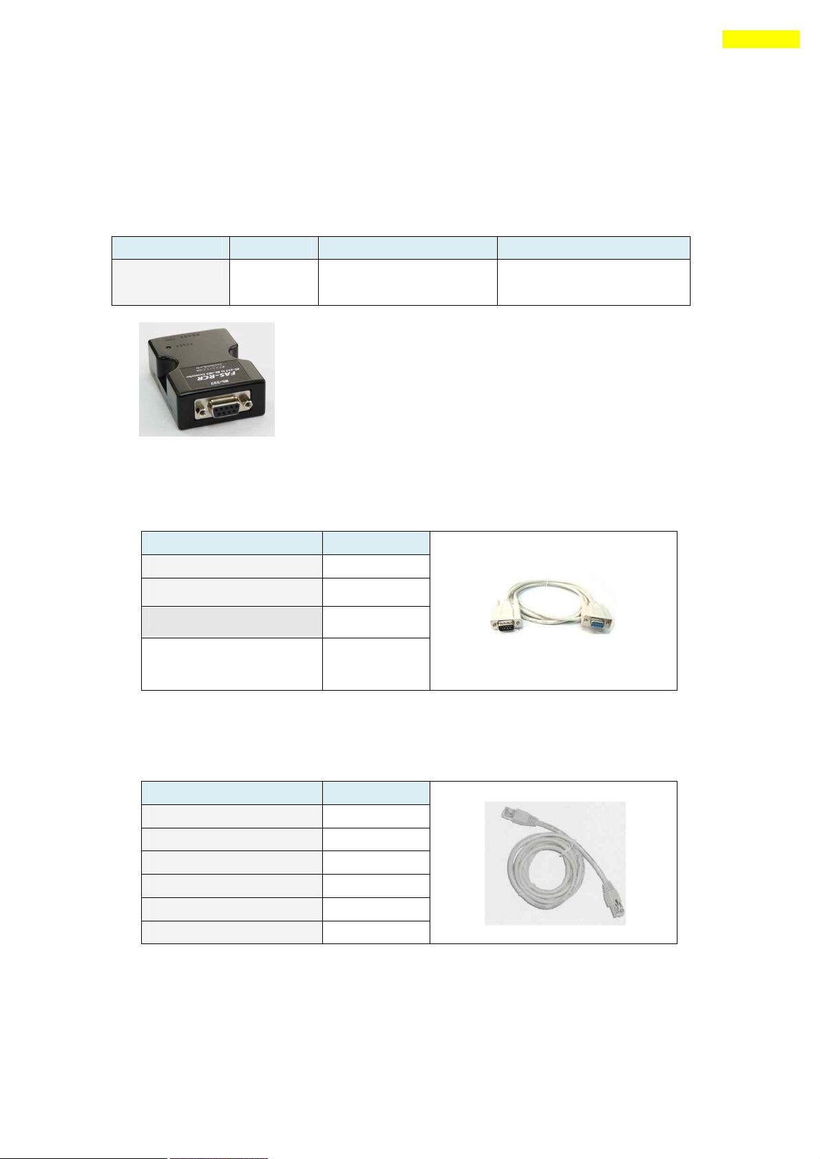
Option for RS-485 Communication
■ RS485 Converter
Available to communicate the PC and the drive. One module per multi -drop link is required.
FAS-RCR
■ RS-232 Connection Cable for FAS-RCR
Universal DB-9 male-female type cable is used.
For more information wiring diagram and connector, refer to 「10. Communication Function」.
■ RS-485 Connection Cable : for Ezi-STEP-PR
Universal RJ-45 (STP:CAT5 category) straight type cable is used.
For more information wiring diagram and connector, refer to 「10. Communication Function」.
For cabling position, refer to ⑤ of 「5.2 Controller Configuration 」.
www.fastech.co.kr
Page 63

63
Appendix
Item
Length
CGNA-R-0R5F
50cm
CGNA-R-001F
100cm
CGNA-R-1R5F
150cm
CGNA-R-002F
200cm
CGNA-R-003F
300cm
CGNA-R-005F
500cm
■ RS-485 Connection Cable :for Ezi -STEP-PR-MI
www.fastech.co.kr
Page 64
64
Appendix
Use
Item
Specification
Maker
Terminal Block
connector
Connector
DB-26 male type
Drive
connector(CN1)
Connector Housing
Backshell
10126-30000VE
10320-52AO-008
3M
3M
Type
Item
Interface (Terminal
Block) Board
TB-Plus
No. of
CN1
Signal
name
Signal name of
TB-Plus
1
Limit+
L+
2
Limit-
L-
3
Origin
ORI
4
IN1
I1
5
IN6
I6
6
IN7
I7
14
IN2
I2
15
IN3
I3
16
IN4
I4
17
IN5
I5
18
IN8
I8
19
IN9
I9
No. of
CN1
Signal
name
Signal name of
TB- Plus
7
COMP
CO
8
OUT1
O1
9
OUT2
O2
10
OUT3
O3
11
OUT4
O4
12
OUT5
O5
13
OUT6
O6
20
OUT7
O7
21
OUT8
O8
22
OUT9
O9
23
Brake+
B+
24
Brake-
B-
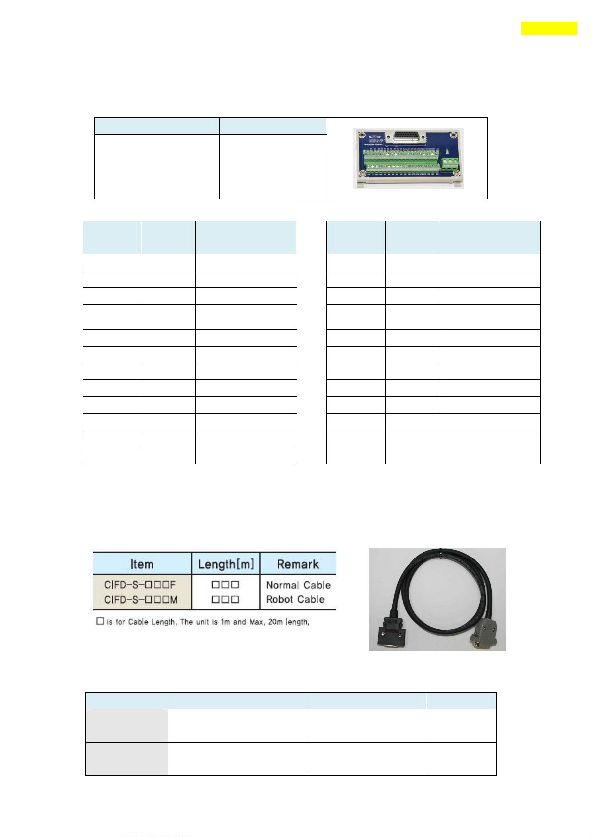
Option for Interface Board
■ Terminal Block
■ Extension cable for Interface Board
Available to extend the distance between the terminal block board and the drive.
The cable connection is 1:1 straight type.
www.fastech.co.kr
Page 65
65
Appendix
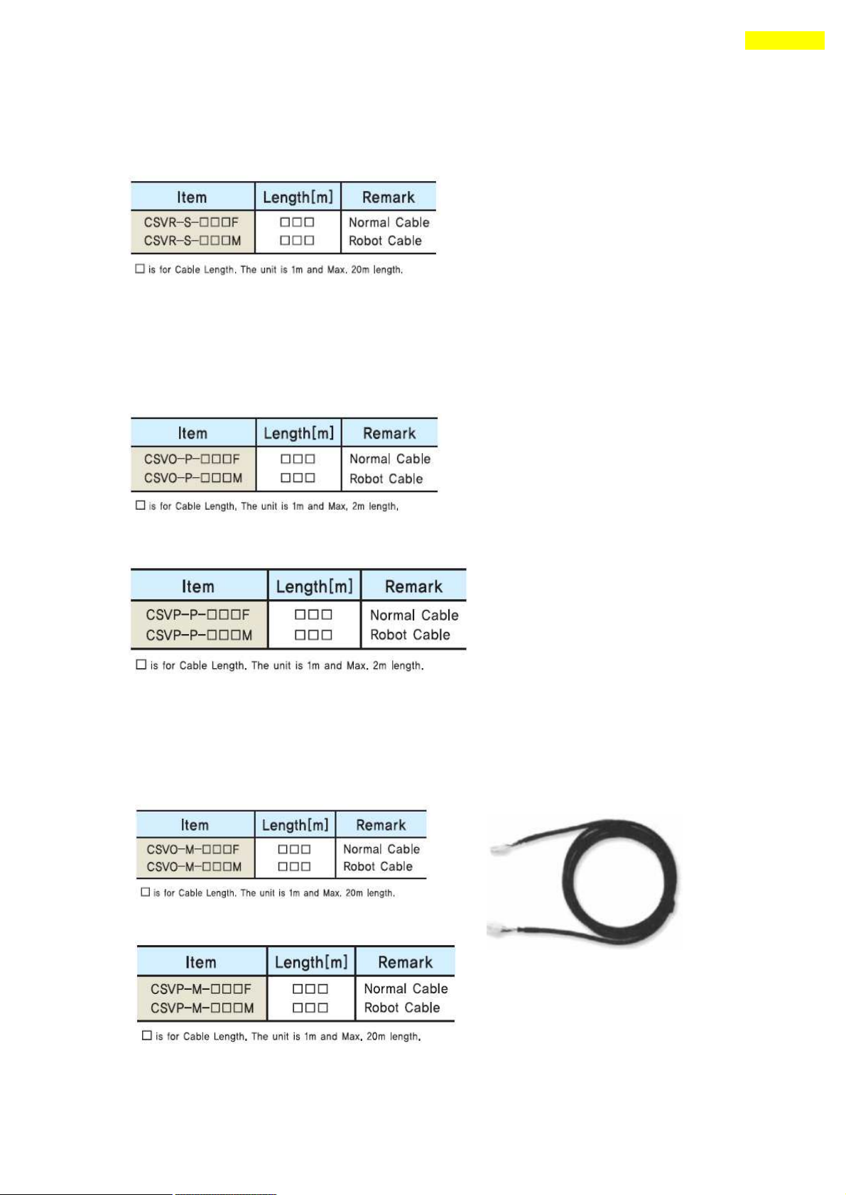
Option for Motor Drive : for Ezi-STEP-PR
■ Cable for Input/Output Signal
Available to connect between Control S ystem and Ezi-STEP Plus-R.
Refer to ① of 「5.2 Controller Configuration」.
■ Cable for Power
Available to connect between Power and Ezi-STEP Plus-R.
Next is for 86mm drive.
Refer to ④ of 「5.2 Controller Configuration」.
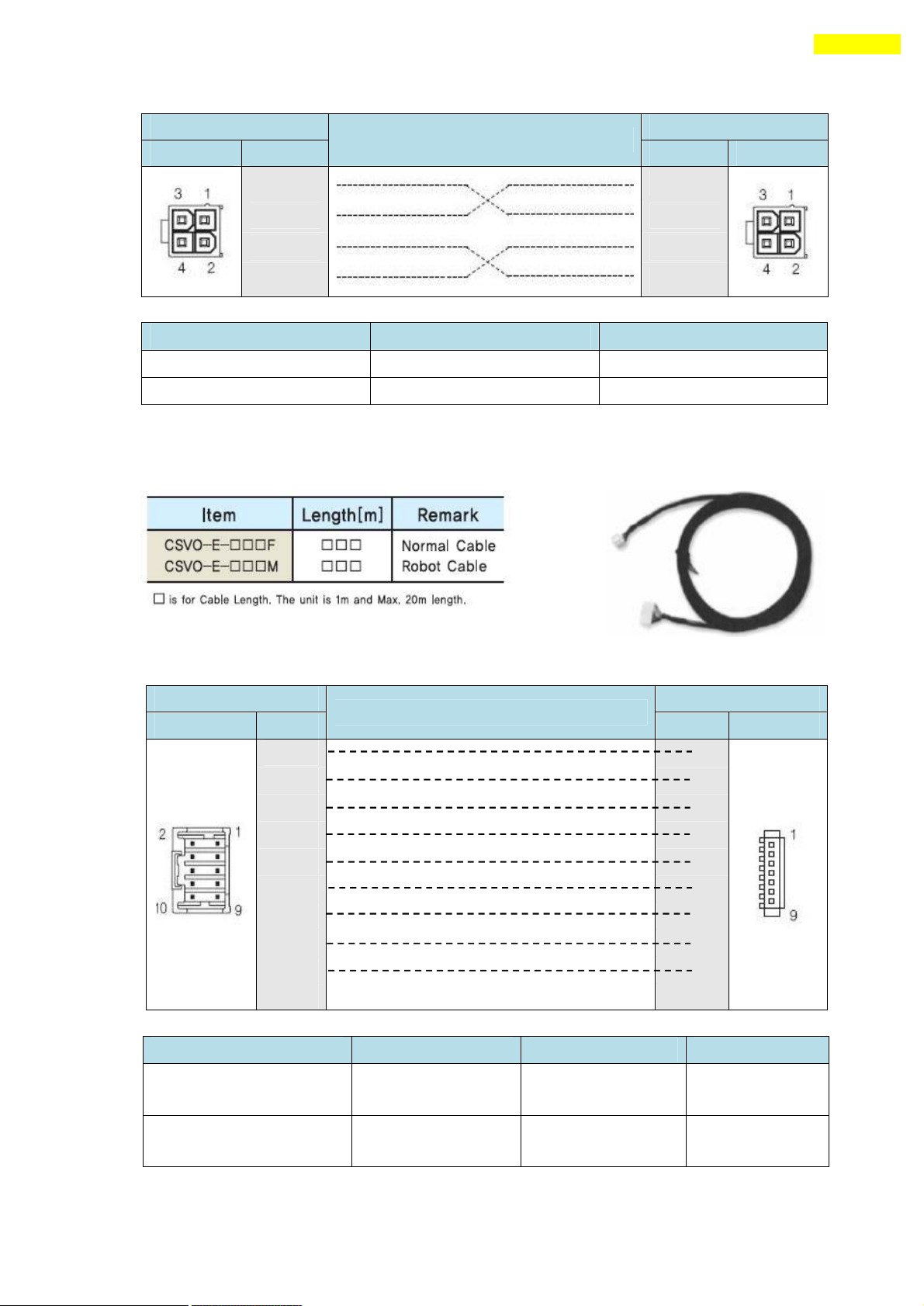
■ Extension Cable for Motor
Available to extended conne ction between motor and Ezi-STEP Plus-R.
Next is for 86mm drive.
Refer to ③ of 「5.2 Controller Configuration」.
www.fastech.co.kr
Page 66
66
Appendix
Drive Connector(CN3)
Cable Connection
Motor Connector
Pin Layout
Pin No.
Pin No.
Pin Layout
1 1
2
2
3
3
4
4
Item
Specification
Maker
Housing
5557-04
MOLEX
Terminal
5556
MOLEX
Drive Connector(CN2)
Cable Connection
Motor Connector
Pin Layout
Pin No.
Pin No.
Pin Layout
1
1
2 2
3 3
4 4
5 5
6 6
7 7
8 8
9 9
10
Type
Item
Specification
Maker
Drive Connector (CN2)
Housing
Terminal
51353-100
56134-9000
MOLEX
MOLEX
Motor Connector
Housing
Terminal
SMP-09V-NC
SHF-001T-0.8BS
JST
JST
Wiring Diagram
Connector Specification
■ Extension cable for Encoder
Available to extend the distance between the encoder and Ezi-STEP Plus-R.
Refer to ② of 「5.2 Controller Configuration」.
Wiring Diagram
Connector Specification
www.fastech.co.kr
Page 67
67
Appendix
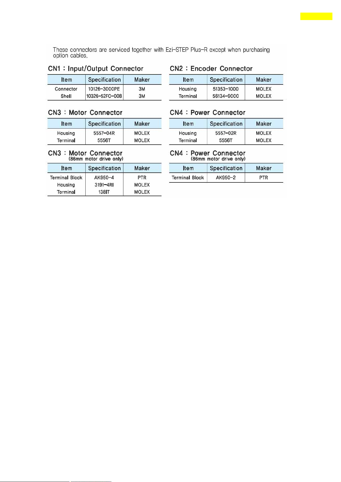
■ Connector for cabling
www.fastech.co.kr
Page 68
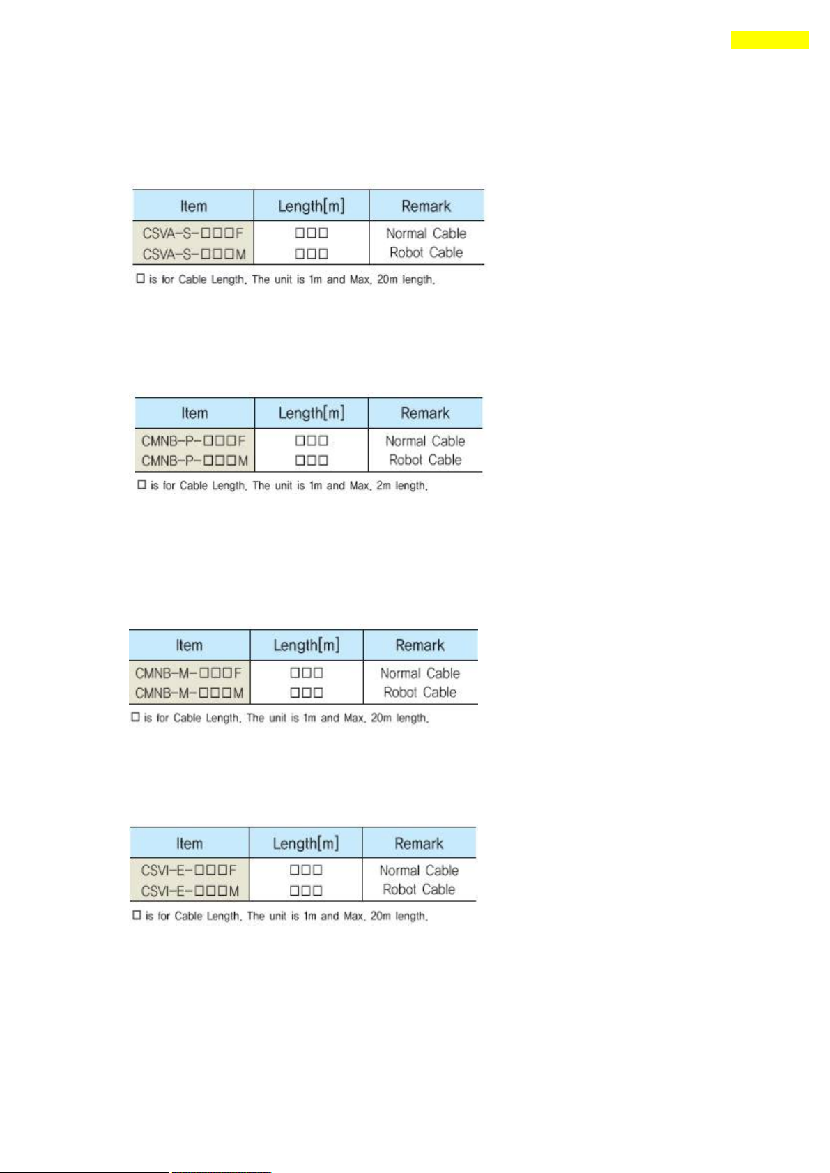
68
Appendix
Option for Motor Drive : f or Ezi-STEP-PR-MI
■ Cable for Input/Output Signal
Available to connect between Control S ystem and Ezi-STEP-PR-MI.
Refer to ① of 「5.2 Controller Configuration」.
■ Cable for Power
Available to connect between Power and Ezi -STEP-PR-MI.
Refer to ④ of 「5.2 Controller Configuration」.
■ Extension Cable for Motor
Available to extended connection between motor and Ezi -STEP-PR-MI.
Refer to ③ of 「5.2 Controller Configuration」.
■ Extension cable for Encoder
Available to extend the distance between the encoder and Ezi -STEP-PR- MI.
Refer to ② of 「5.2 Controller Configuration」.
■ Connector for cabling
These connectors are serviced together with Ezi -STEP-PR-MI except when purchasing
Option cables.
www.fastech.co.kr
Page 69
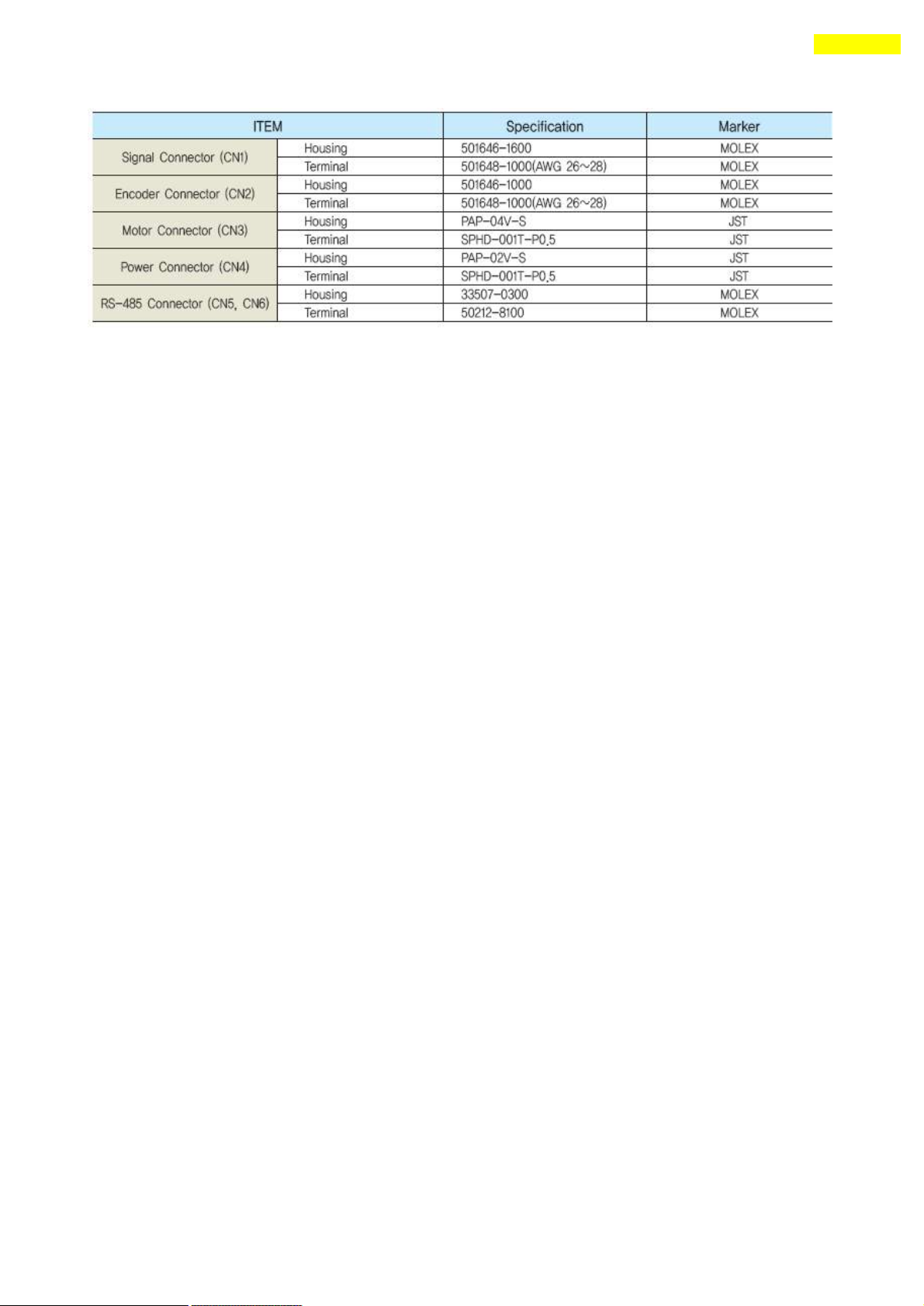
69
Appendix
www.fastech.co.kr
Page 70

70
Appendix
ⓒ Copyright 2008 FASTECH Co.,Ltd.
All Rights Reserved Sep 13, 2012 rev.08.05.027
www.fastech.co.kr
 Loading...