

Page 1
User Manual
Text
( Rev.08.06.23)
www.fastech.co.kr
Page 2

2
1. Safety Pre-cautions
- Table of Contents -
1. Safety Pre-cautions ....................................................... 5
2. Specifications of the Drive ............................................... 8
2.1 Characteristic Table .................................................................. 8
2.2 Dimensions ........................................................................... 11
3. Specifications of the Motor ...............................................12
3.1 EzM-20 Series ........................................................................ 12
3.2 EzM-28 Series ........................................................................ 13
3.3 EzM-35 Series ........................................................................ 14
3.4 EzM-42 Series ........................................................................ 15
3.5 EzM-56 Series ........................................................................ 17
3.6 EzM-60 Series ........................................................................ 19
3.7 EzM-86 Series ........................................................................ 21
4. Characteristics of Motor Torque............................................22
4.1 Ezi-SERVO-PR ......................................................................... 22
4.2 Ezi-SERVO PR-MI ...................................................................... 24
4.3 Ezi-SERVO-ALL ........................................................................ 25
5. Configuration of the Controller............................................26
5.1 Combination of Motor and Drive ....................................................... 26
5.2 Controller Configurtion .............................................................. 31
5.3 External Wiring Diagram .............................................................. 34
6. External Name and Function Setting of Ezi-SERVO-PR .........................40
6.1 Appearance and Part Name ............................................................. 40
6.2 Status Display LED ................................................................... 41
6.3 Drive ID Switch Selection (SW1) ...................................................... 41
6.4 Communication Speed and Terminal Resistance Select Switch(SW2) ........................ 41
6.5 Motor Connection (CN3) ............................................................... 42
6.6 Encoder Connection (CN2) ............................................................. 42
6.7 Power Connection(CN4) ................................................................ 42
www.fastech.co.kr
Page 3

3
1. Safety Pre-cautions
6.8 I/O Signal Connection (CN1) .......................................................... 42
6.9 Communication Connecttion (CN5) ...................................................... 43
7. External Name and Function Setting of Ezi-SERVO-PR-MI ......................44
7.1 Appearance and Part Name ............................................................. 44
7.2 Drive ID Switch Selection (SW1) and 7-segmant ......................................... 44
7.3 Communication Speed and Terminal Resistance Select Switch(SW2) ........................ 44
7.4 Motor Connection (CN3) ............................................................... 45
7.5 Encoder Connection (CN2) ............................................................. 45
7.6 Power Connection(CN4) ................................................................ 45
7.7 I/O Signal Connection (CN1) .......................................................... 46
7.8 Communication Connection (CN5) ....................................................... 46
8. External Name and Function Setting of Ezi-SERVO-ALL42 / ALL56 ...............47
8.1 Appearance and Part Name ............................................................. 47
8.2 Terminal Resistance Select Switch(SW1) ............................................... 47
8.3 Drive ID Switch Selection (SW2) ...................................................... 47
8.4 Communication Speed Select Switch(SW3) ............................................... 47
8.5 I/O Signal Connection (CN1) .......................................................... 48
8.6 Power Connection(CN2) ................................................................ 48
8.7 Communication Connection (CN3, CN4) .................................................. 48
9. External Name and Function Setting of Ezi-SERVO-ALL60 ......................49
9.1 Appearance and Part Name ............................................................. 49
9.2 Terminal Resistance Select Switch(SW1) ............................................... 49
9.3 I/O Signal Connection (CN3) .......................................................... 49
9.4 Power Connection(CN1) ................................................................ 50
9.5 Communication Connection (CN5, CN6) .................................................. 50
10. Control I/O Signal .......................................................51
10.1 Signal Cabling (Ezi-SERVO-PR type) .................................................. 51
10.2 Signal Cabling (Ezi-SERVO-ALL type) ................................................. 52
10.3Connection Circuit ................................................................... 53
10.4 Input Signal ........................................................................ 55
10.5 Output Signal ....................................................................... 64
www.fastech.co.kr
Page 4

4
1. Safety Pre-cautions
11. Operation ................................................................68
11.1 Power Supply Timing ................................................................. 68
11.2 Servo ON Operation .................................................................. 68
11.3 Operation Mode ...................................................................... 68
12. Other Operation Functions ................................................70
12.1 Position Table(PT) Operation Example ................................................ 70
12.2 Jog Operation Example ............................................................... 70
12.3 Origin Return ....................................................................... 71
12.4 Stop Operation ...................................................................... 75
12.5 Trigger Pulse Output ................................................................ 75
12.6 Push Motion ......................................................................... 77
13. Communication Function ...................................................81
13.1 Connection with the PC .............................................................. 81
13.2 Communication Interface Circuit ..................................................... 83
14. Protective Function ......................................................84
14.1 Alarm Type .......................................................................... 84
14.2 Acquiring Alarm Information ......................................................... 84
14.3 Alarm Check and Release ............................................................. 85
14.4 Alarm Log ........................................................................... 86
15. Parameter ................................................................87
15.1 Parameter List ...................................................................... 87
15.2 Encoder Setup ....................................................................... 88
15.3 Parameter Description ............................................................... 89
Appendix .....................................................................94
www.fastech.co.kr
Page 5
5
1. Safety Pre-cautions
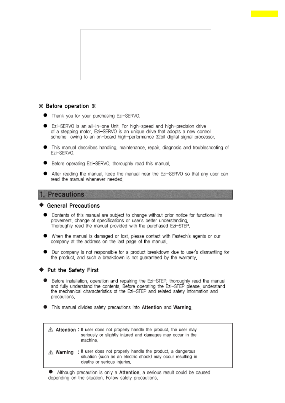
Manual Version ; [ver08.06.23]
Provided Firmware version : 6.x.063.50 ~
Provided GUI version : 6.25.1.628 ~
Fisrt Edition : Oct 02, 2008
Revised Edition : Mar 20, 2018
1. Safety Pre-cautions
www.fastech.co.kr
Page 6
6
1. Safety Pre-cautions
www.fastech.co.kr
Page 7
7
1. Safety Pre-cautions
Notes on Installation
1) This product has been designed for indoor uses. The ambient temperature of the room
should be 0℃~55℃.
2) If the temperature of the case is 50℃ or higher, radiate heat outside to cool down.
3) Do not install this product under direct rays or near magnetic or radioactive
objects.
4) If more than 2 drives are installed in a line, keep the interval of 20mm or more
vertically and 50mm or more horizontally at least.
www.fastech.co.kr
Page 8
8
2. Specifications of the Drive
2. Specifications of the Drive
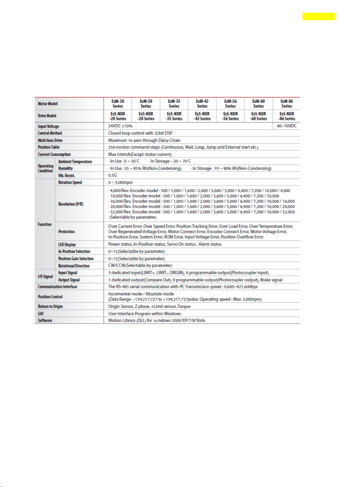
2.1 Characteristic Table
1) Ezi-SERVO-PR
www.fastech.co.kr
Page 9
9
2. Specifications of the Drive
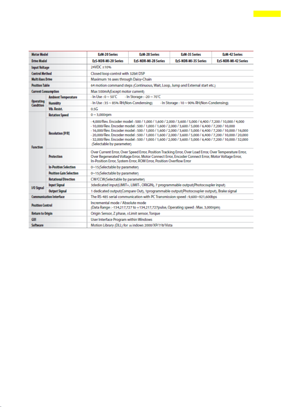
2) Ezi-SERVO-PR-MI
www.fastech.co.kr
Page 10
10
2. Specifications of the Drive
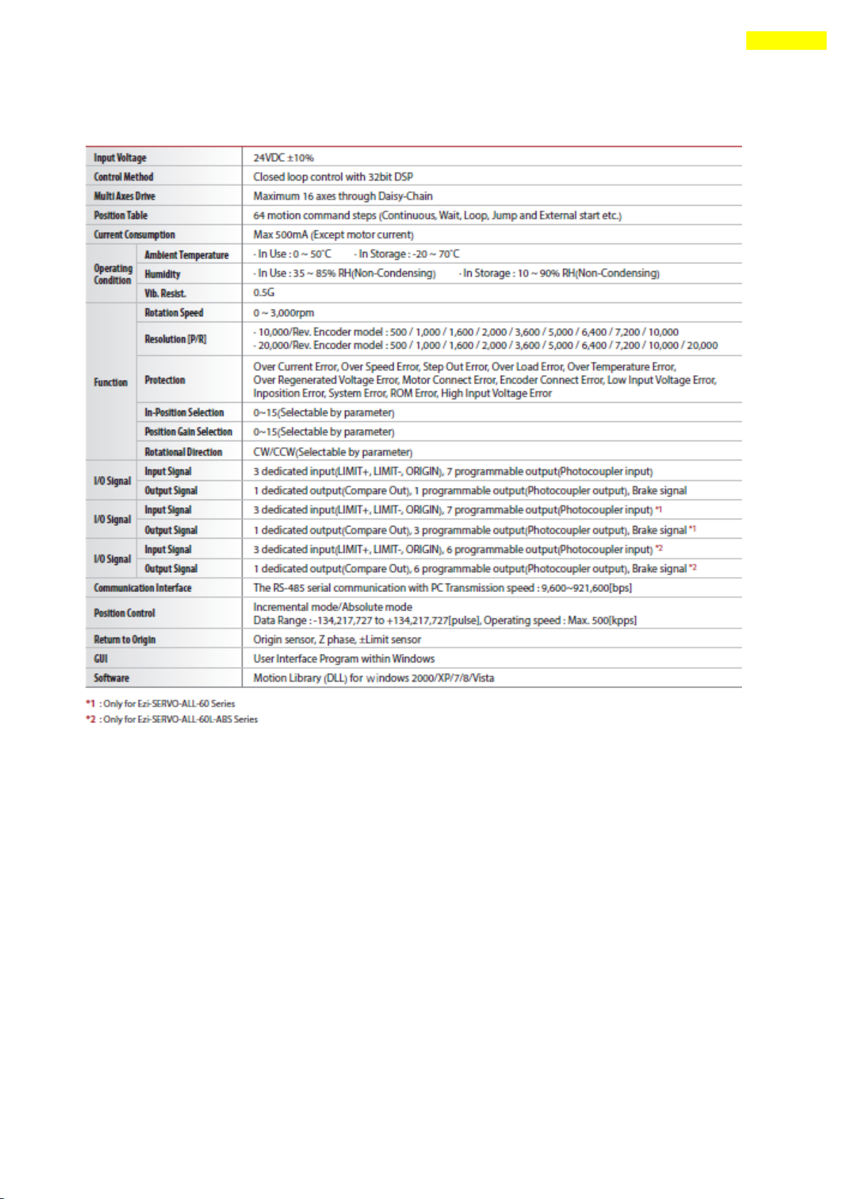
3) Ezi-SERVO-ALL
www.fastech.co.kr
Page 11
11
2. Specifications of the Drive
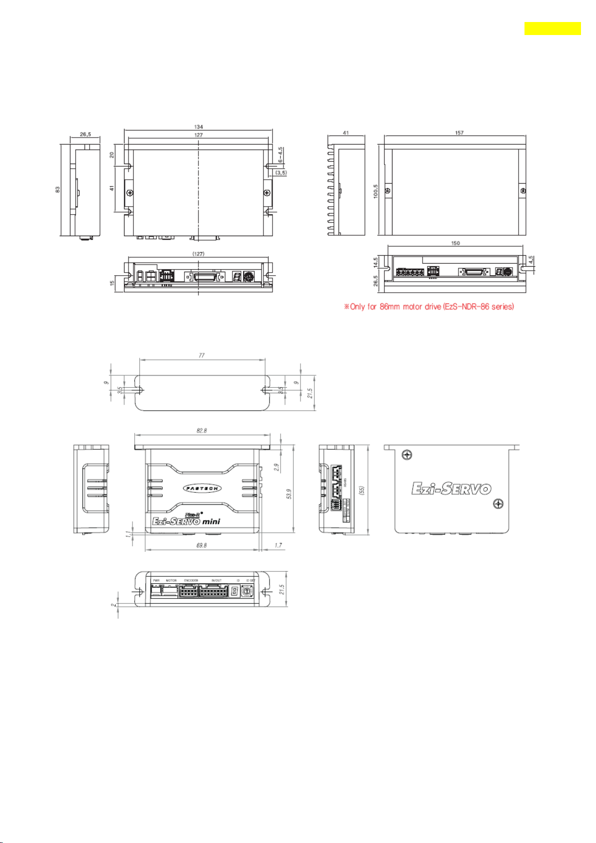
2.2 Dimensions
1) Ezi-SERVO-PR
2) Ezi-SERVO-PR-MI
3) Ezi-SERVO-ALL
For more information, refer to ‘3.Specifications of Motor’.
www.fastech.co.kr
Page 12
12
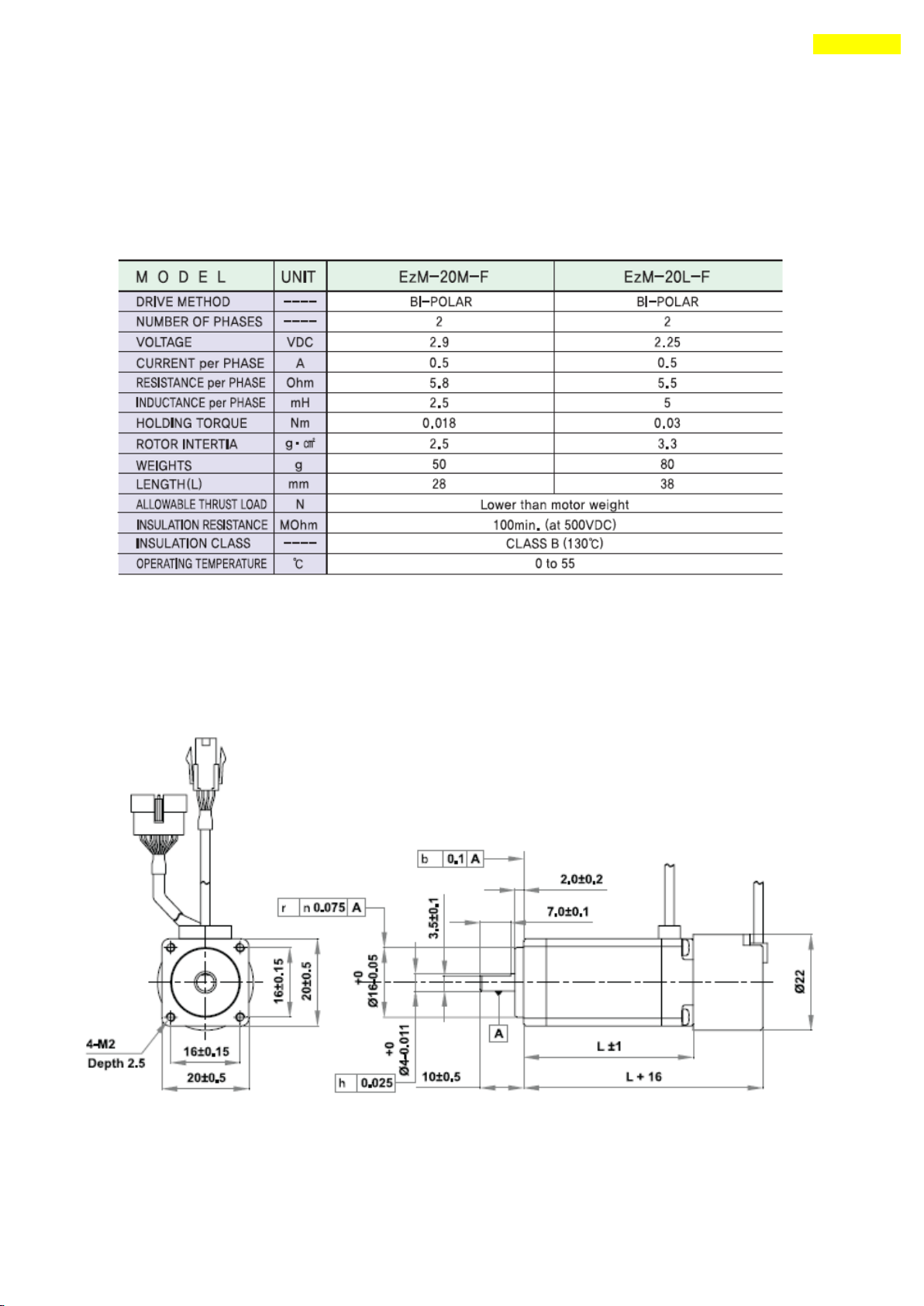
3. Specifications of the Motor
3. Specifications of the Motor
3.1 EzM-20 Series
1) Specifications
2) Dimensions
www.fastech.co.kr
Page 13
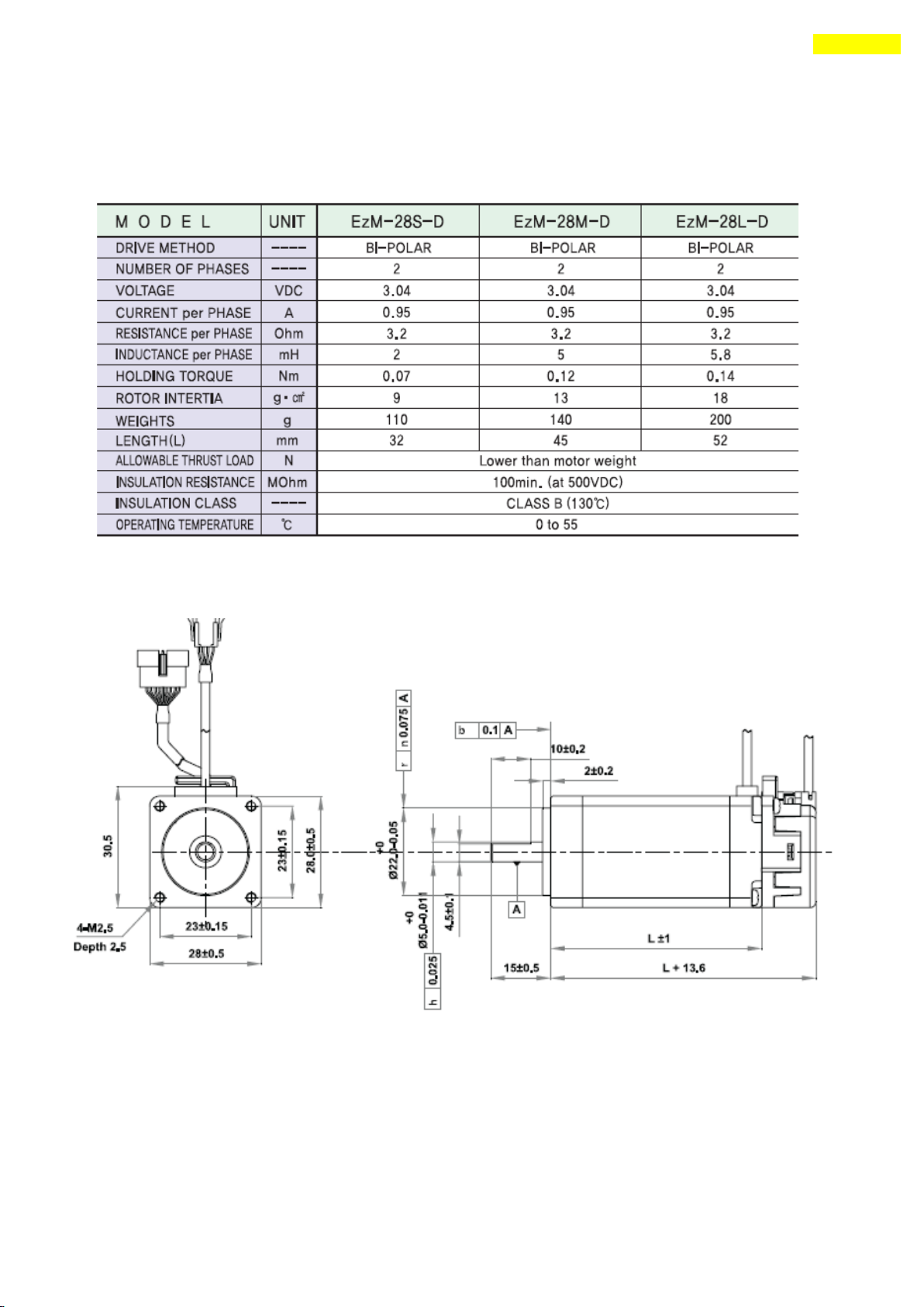
13
3. Specifications of the Motor
3.2 EzM-28 Series
1) Specifications
2) Dimensions
www.fastech.co.kr
Page 14
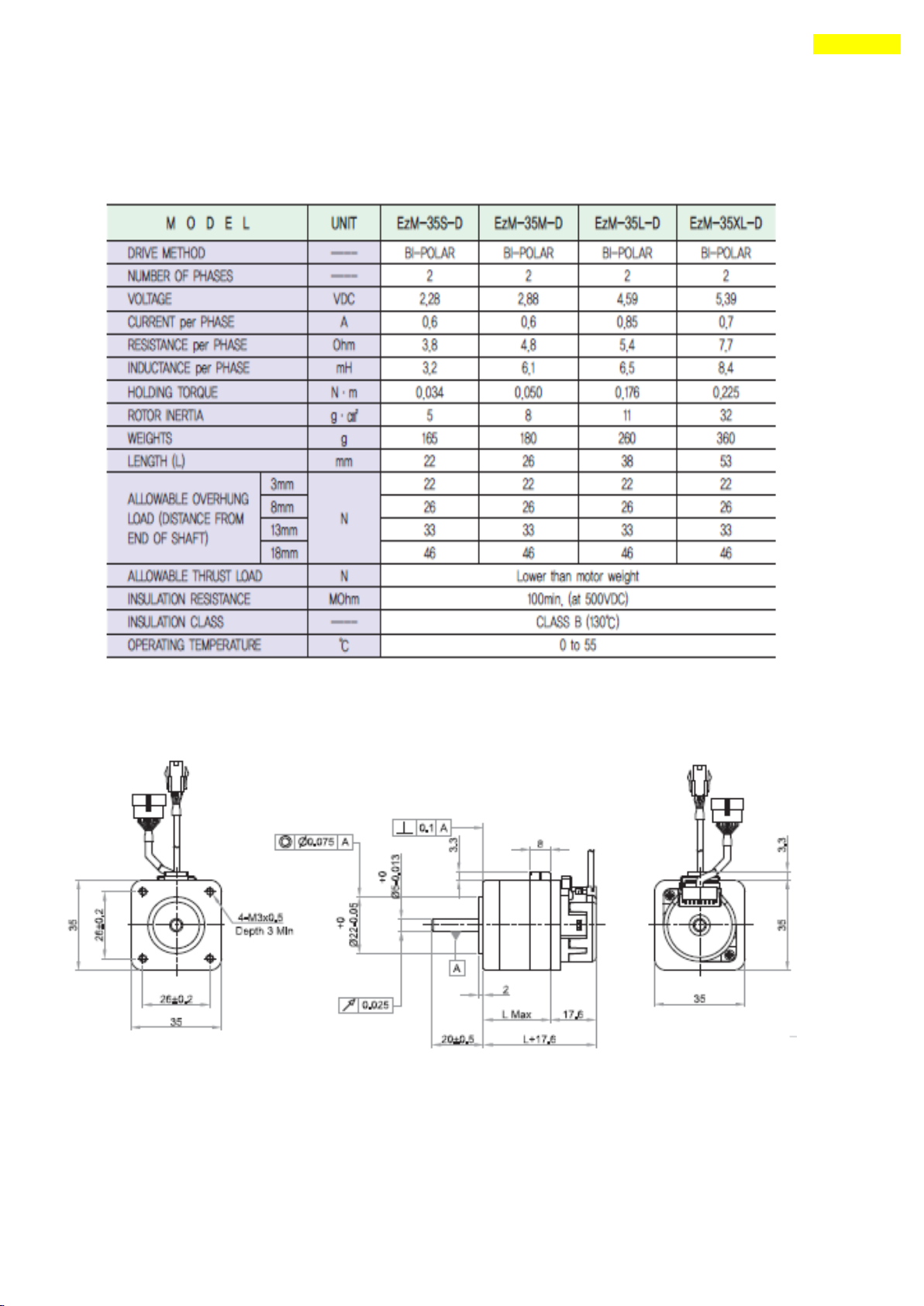
14
3. Specifications of the Motor
3.3 EzM-35 Series
1) Specifications
2) Dimensions
www.fastech.co.kr
Page 15
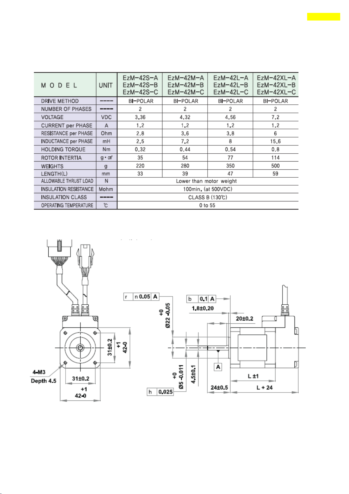
15
3. Specifications of the Motor
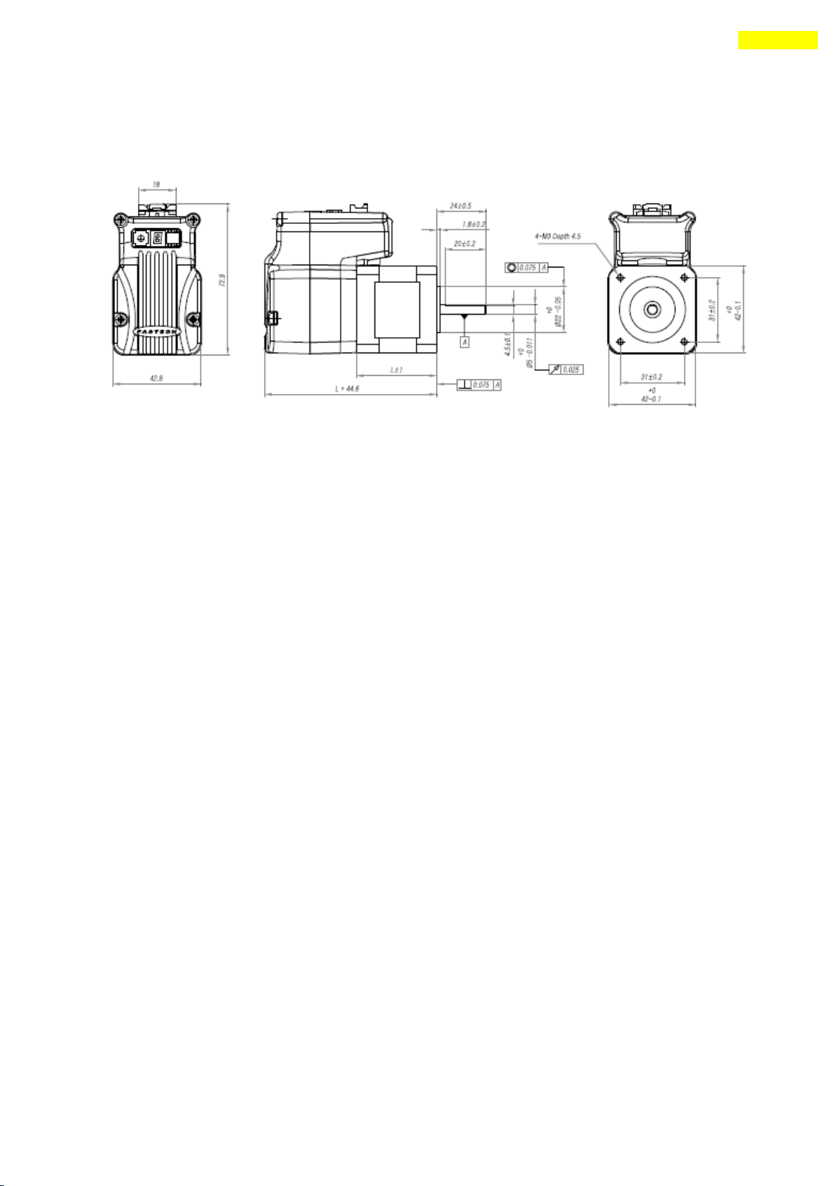
3.4 EzM-42 Series
1) Specifications
2) Dimensions (Ezi-SERVO-PR and Ezi-SERVO-PR-MI)
www.fastech.co.kr
Page 16
16
3. Specifications of the Motor
3) Dimensions (Ezi-SERVO-ALL)
www.fastech.co.kr
Page 17
17
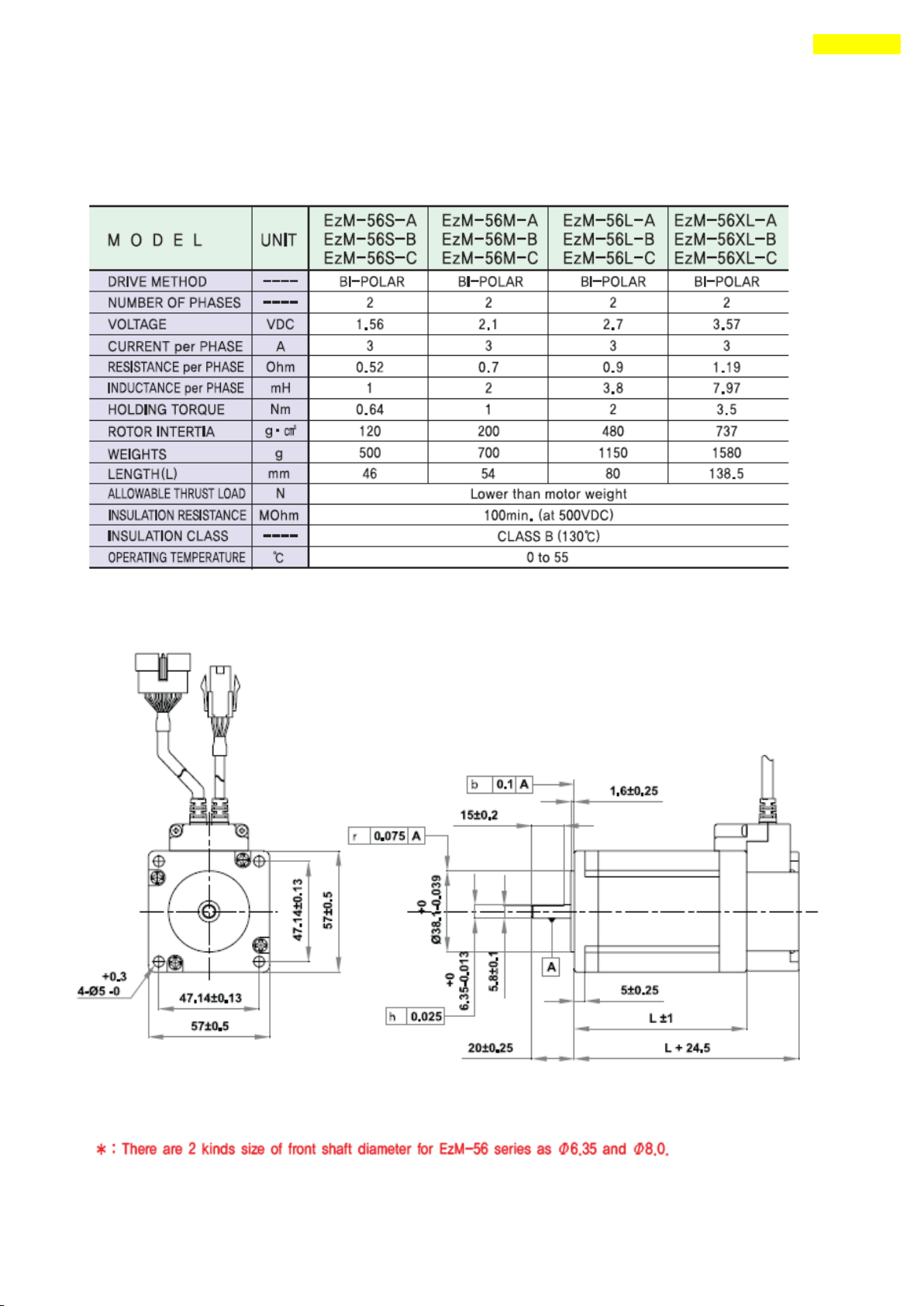
3. Specifications of the Motor
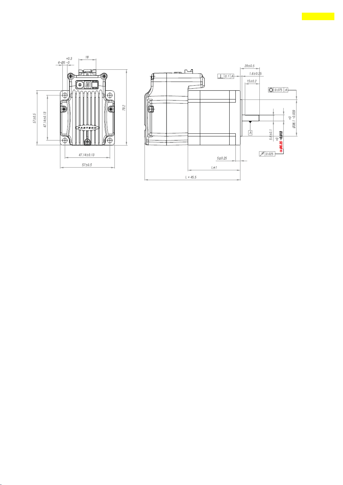
3.5 EzM-56 Series
Ezi-SERVO-PR drive only.
1) Specifications
2) Dimensions (Ezi-SERVO-PR and Ezi-SERVO-PR-MI)
www.fastech.co.kr
Page 18
18
3. Specifications of the Motor
3) Dimensions (Ezi-SERVO-ALL)
www.fastech.co.kr
Page 19
19
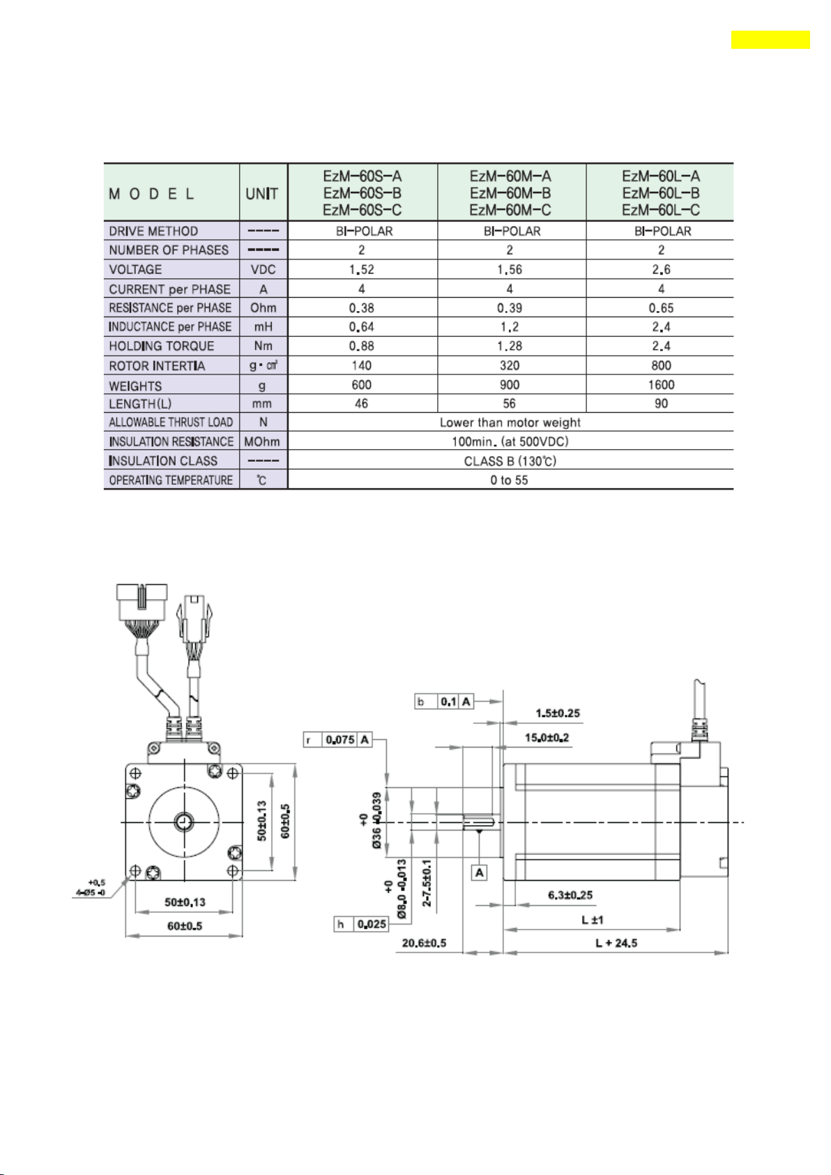
3. Specifications of the Motor
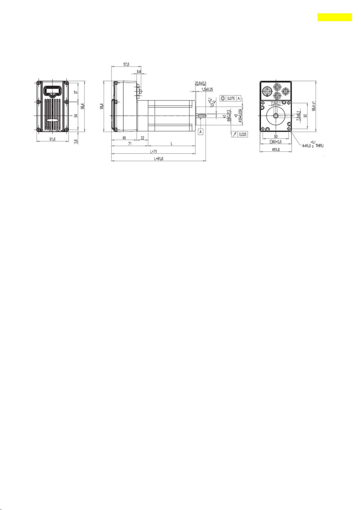
3.6 EzM-60 Series
Ezi-SERVO-PR drive only.
1) Specifications
2) Dimensions (Ezi-SERVO-PR and Ezi-SERVO-PR-MI)
www.fastech.co.kr
Page 20
20
3. Specifications of the Motor
3) Dimensions (Ezi-SERVO-ALL)
www.fastech.co.kr
Page 21
21
3. Specifications of the Motor
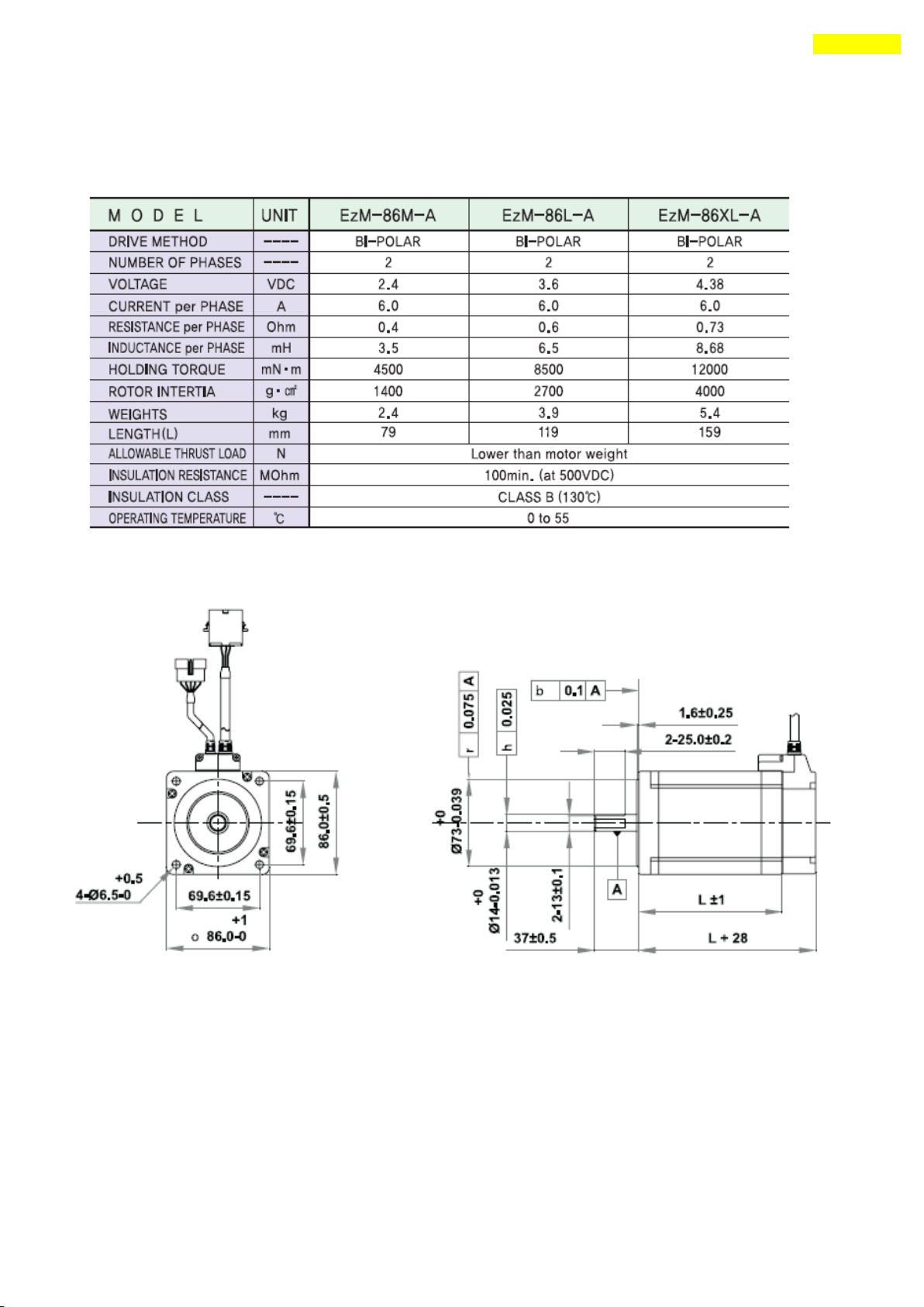
3.7 EzM-86 Series
Ezi-SERVO-PR drive only.
1) Specifications
2) Dimensions
www.fastech.co.kr
Page 22
22
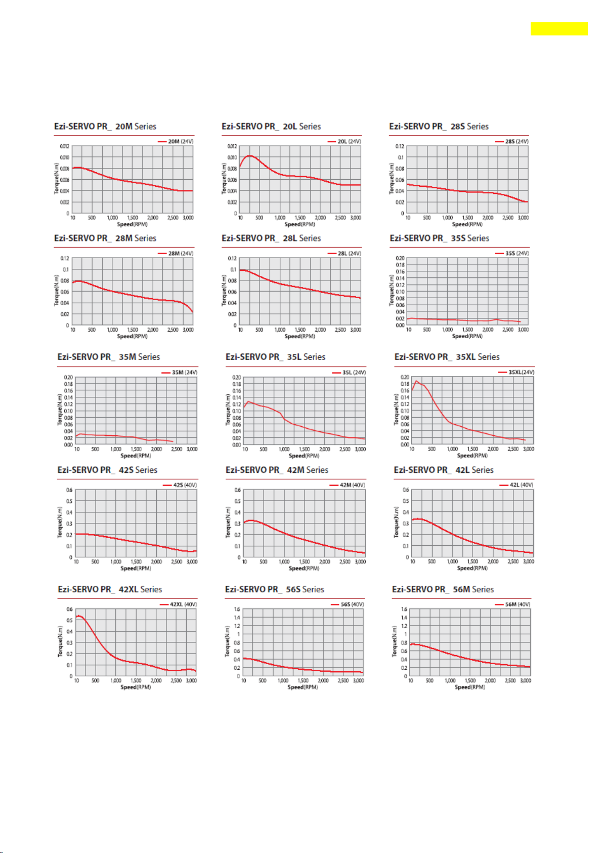
4. Characteristics of Motor Torque
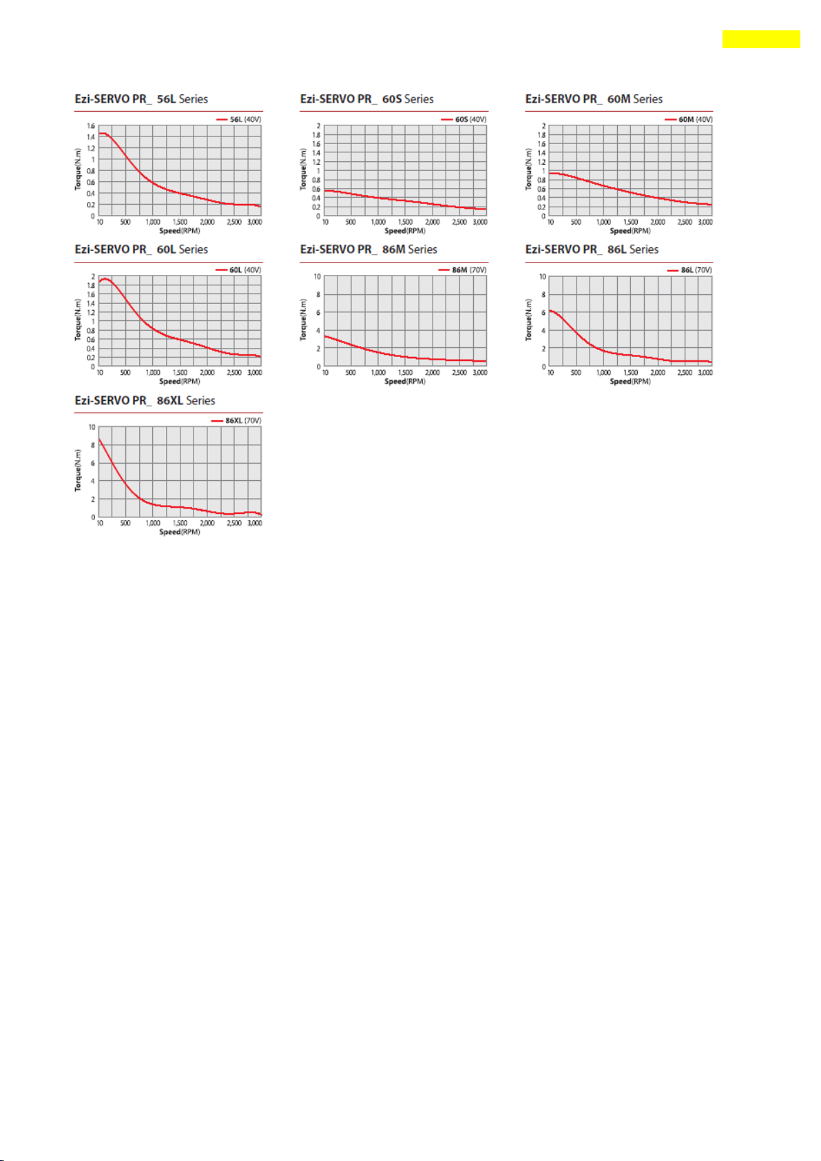
4. Characteristics of Motor Torque
4.1 Ezi-SERVO-PR
www.fastech.co.kr
Page 23
23
4. Characteristics of Motor Torque
www.fastech.co.kr
Page 24
24
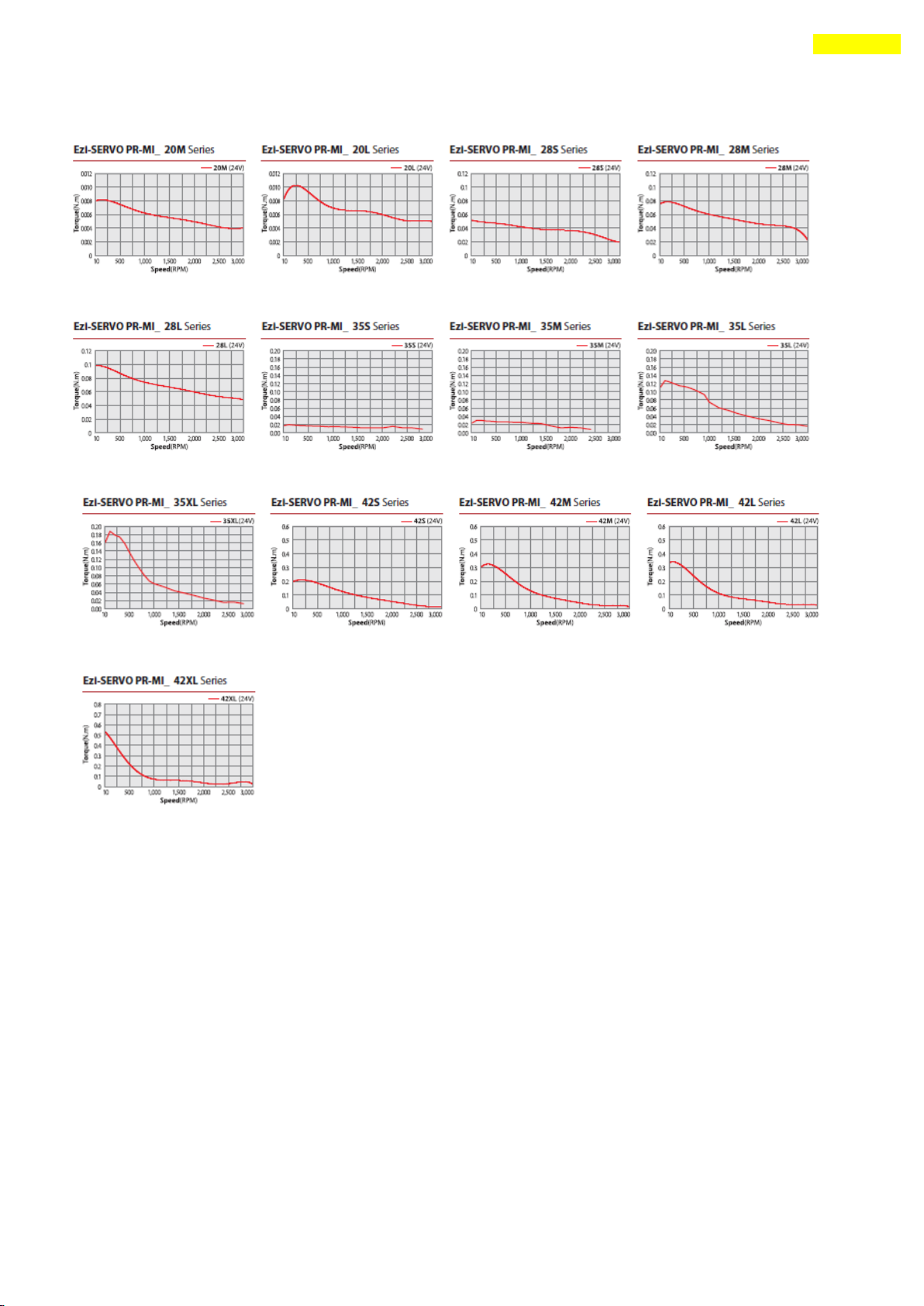
4. Characteristics of Motor Torque
4.2 Ezi-SERVO PR-MI
www.fastech.co.kr
Page 25
25
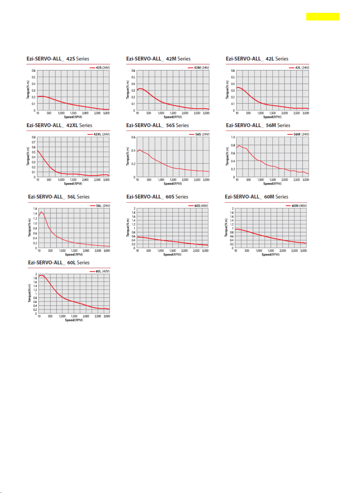
4. Characteristics of Motor Torque
4.3 Ezi-SERVO-ALL
www.fastech.co.kr
Page 26
26
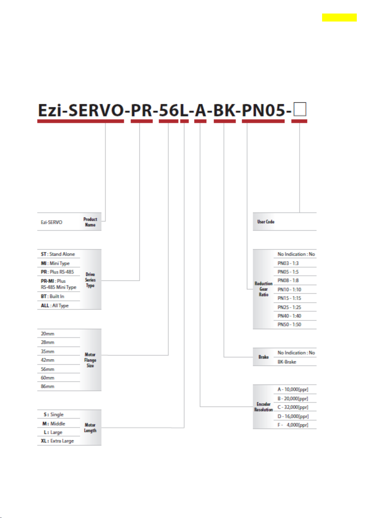
5. Configuration of the Controller
5. Configuration of the Controller
5.1 Combination of Motor and Drive
1) Ezi-SERVO-PR
www.fastech.co.kr
Page 27
27
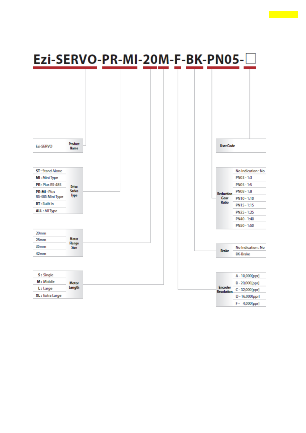
5. Configuration of the Controller
2) Ezi-SERVO-PR-MI
www.fastech.co.kr
Page 28
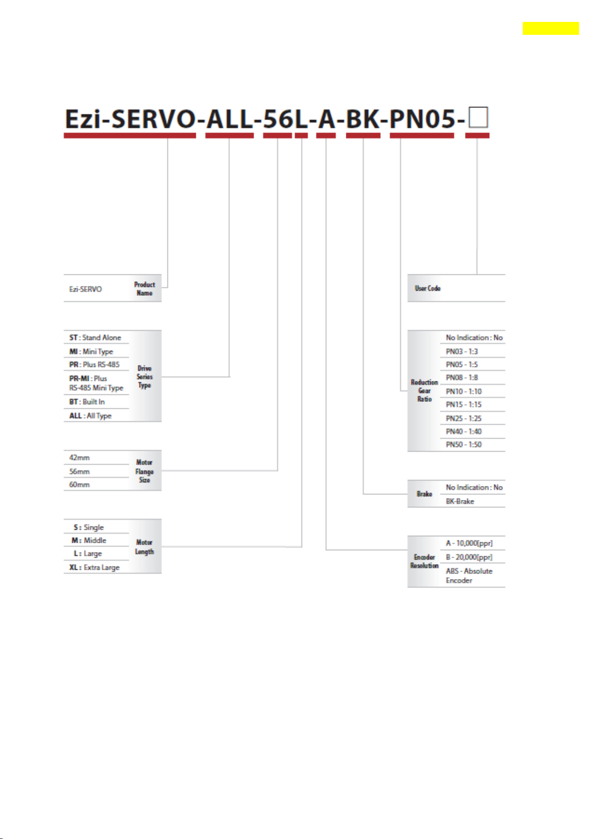
28
5. Configuration of the Controller
3) Ezi-SERVO-ALL
www.fastech.co.kr
Page 29
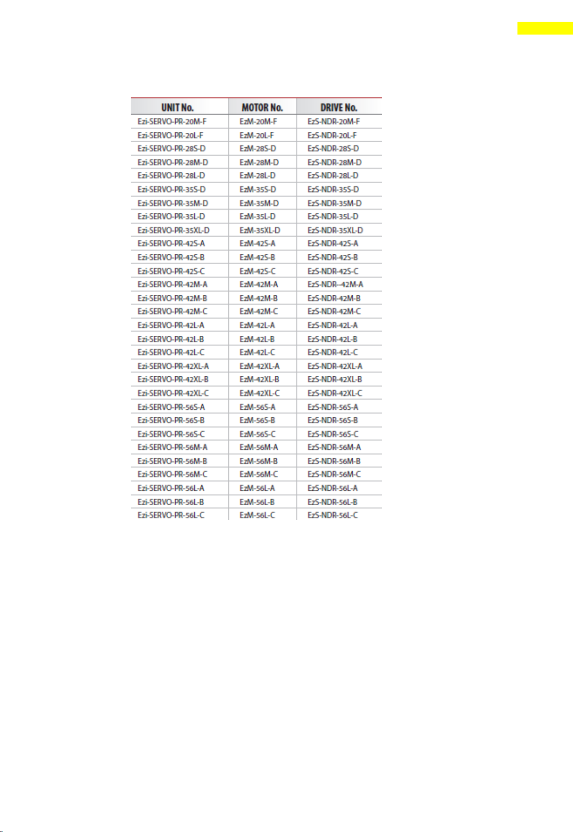
29
5. Configuration of the Controller
4) Combination of Ezi-SERVO-PR
www.fastech.co.kr
Page 30
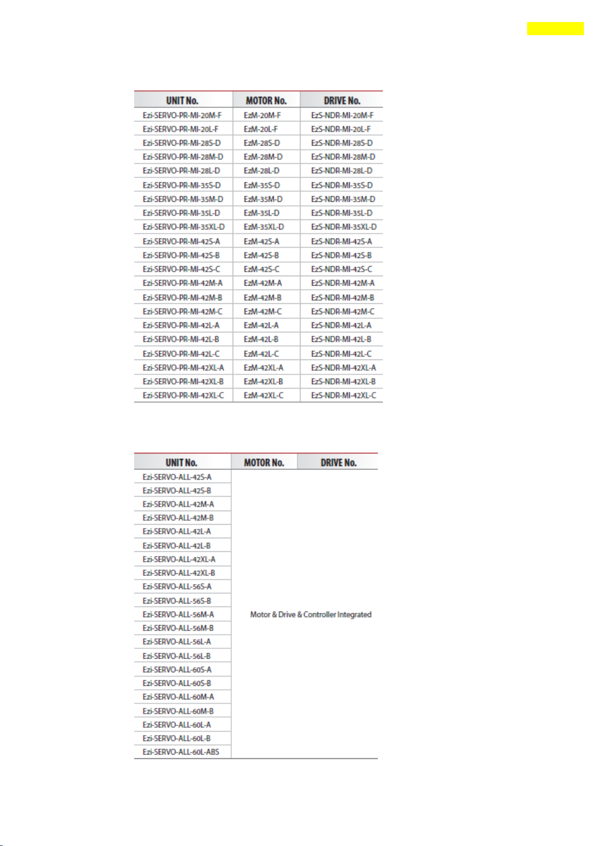
30
5. Configuration of the Controller
5) Combination of Ezi-SERVO-PR-MI
6) Combination of Ezi-SERVO-ALL
www.fastech.co.kr
Page 31
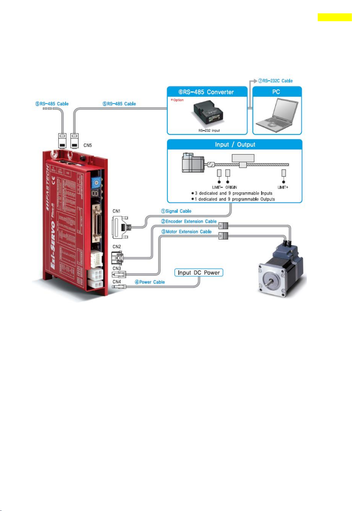
31
5. Configuration of the Controller
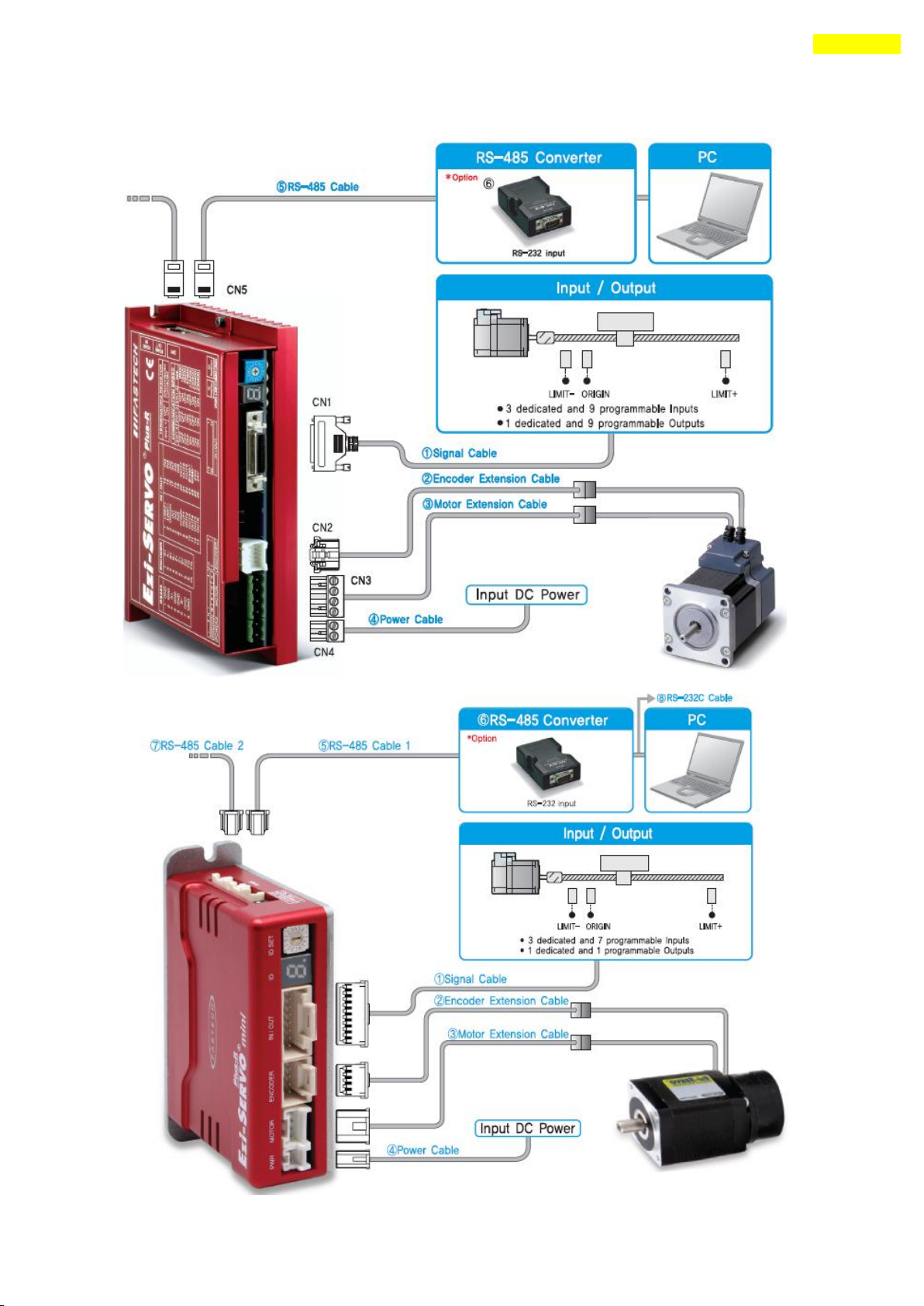
5.2 Controller Configurtion
1) Configuration of Ezi-SERVO-PR20/ Ezi-SERVO-PR28/ Ezi-SERVO-PR42/ Ezi-SERVO-PR56/
Ezi-SERVO-PR60
www.fastech.co.kr
Page 32
32
5. Configuration of the Controller
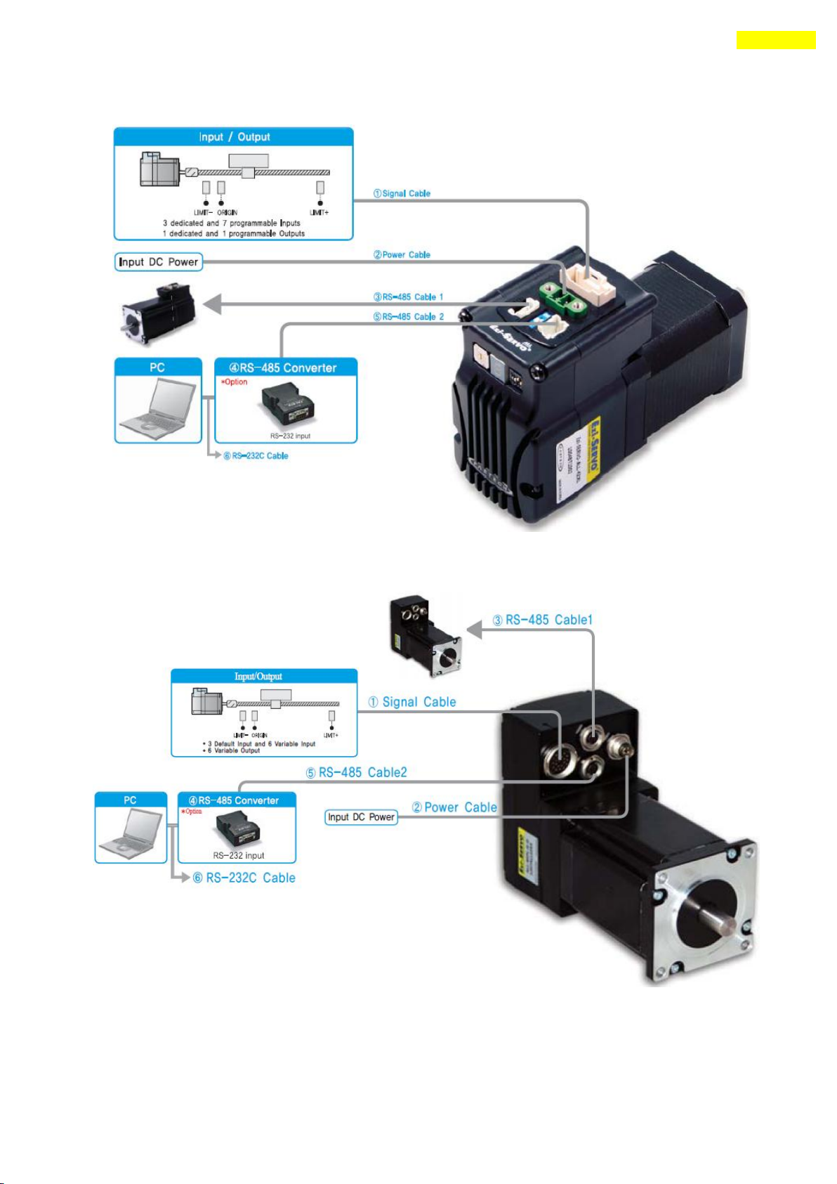
2) Configuration of Ezi-SERVO-PR86
3) Configuration of Ezi-SERVO-PR-MI
www.fastech.co.kr
Page 33
33
5. Configuration of the Controller
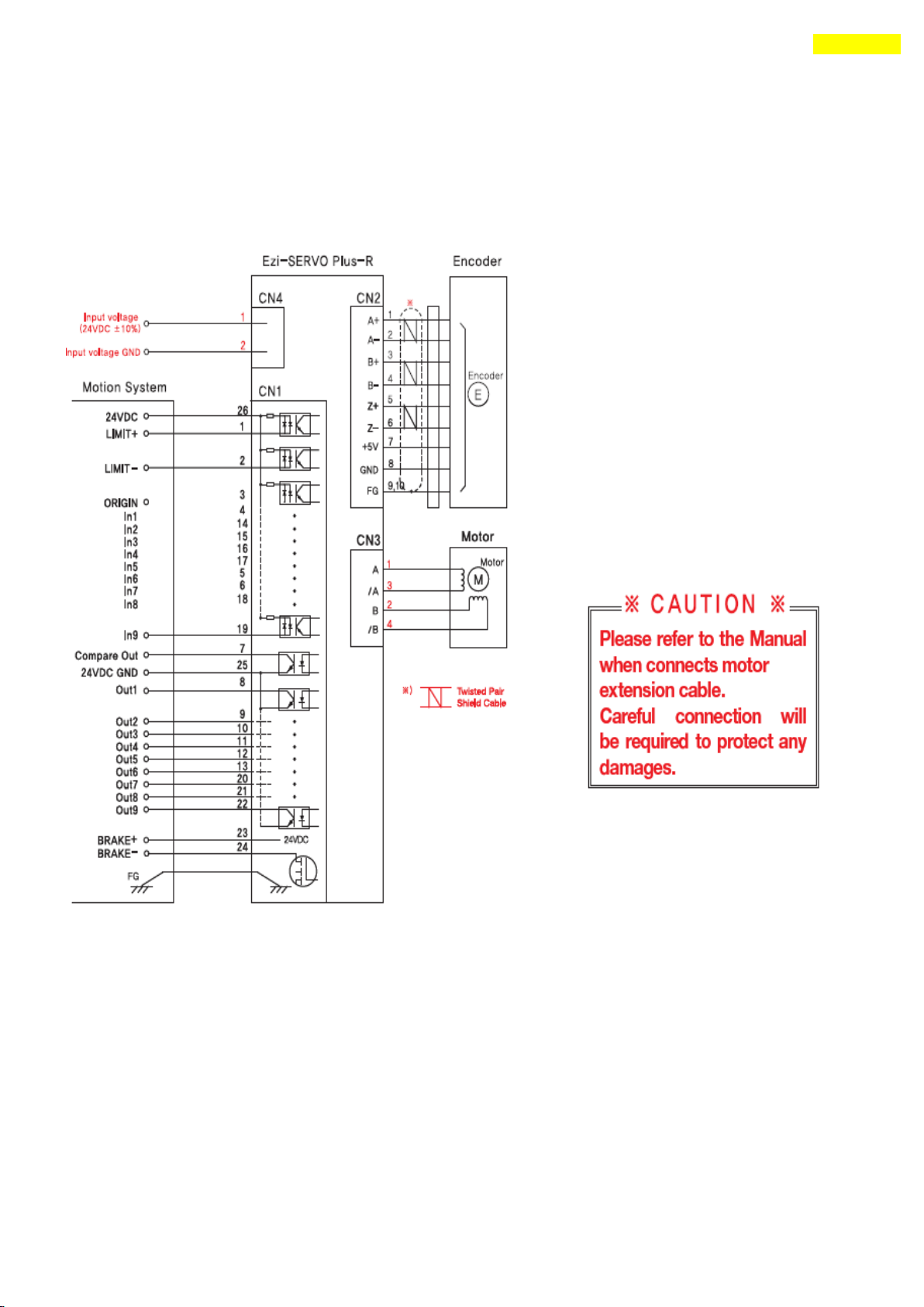
4) Configuration of Ezi-SERVO-ALL42 / Ezi-SERVO-ALL56
5) Configuration of Ezi-SERVO-ALL60
www.fastech.co.kr
Page 34
34
5. Configuration of the Controller
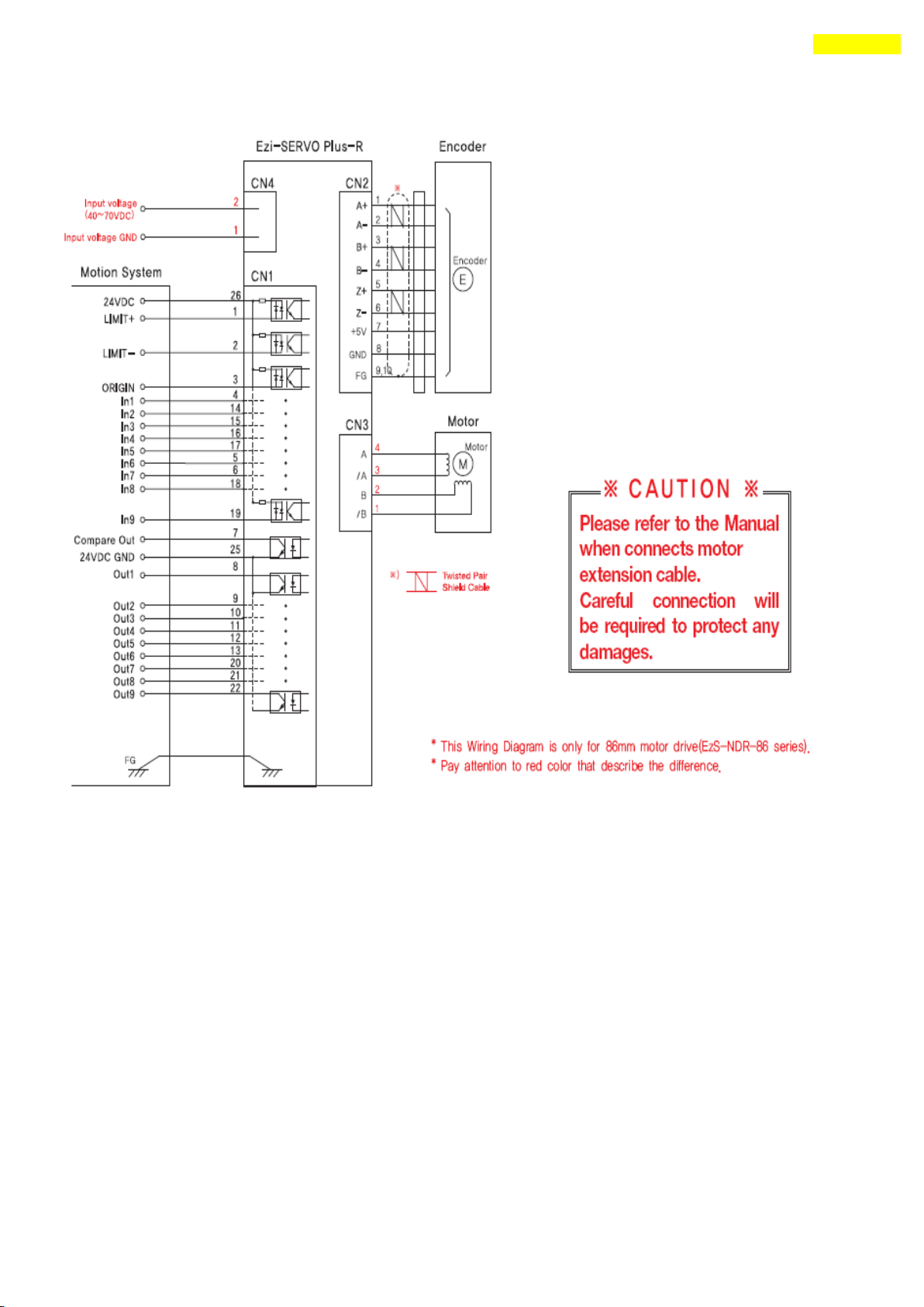
5.3 External Wiring Diagram
1) Wiring of Ezi-SERVO-PR20/ Ezi-SERVO-PR28/ Ezi-SERVO-PR42/ Ezi-SERVO-PR56/
Ezi-SERVO-PR60
www.fastech.co.kr
Page 35
35
5. Configuration of the Controller
2) Wiring of Ezi-SERVO-PR86
www.fastech.co.kr
Page 36
36
5. Configuration of the Controller
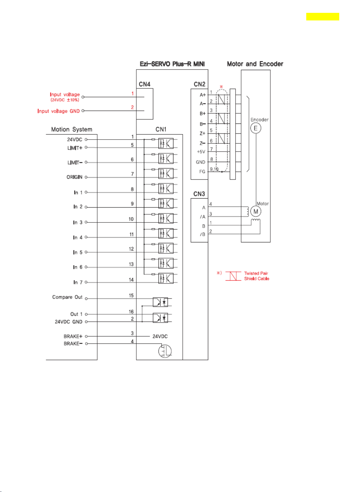
3) Wiring of Ezi-SERVO-PR-MI
www.fastech.co.kr
Page 37
37
5. Configuration of the Controller
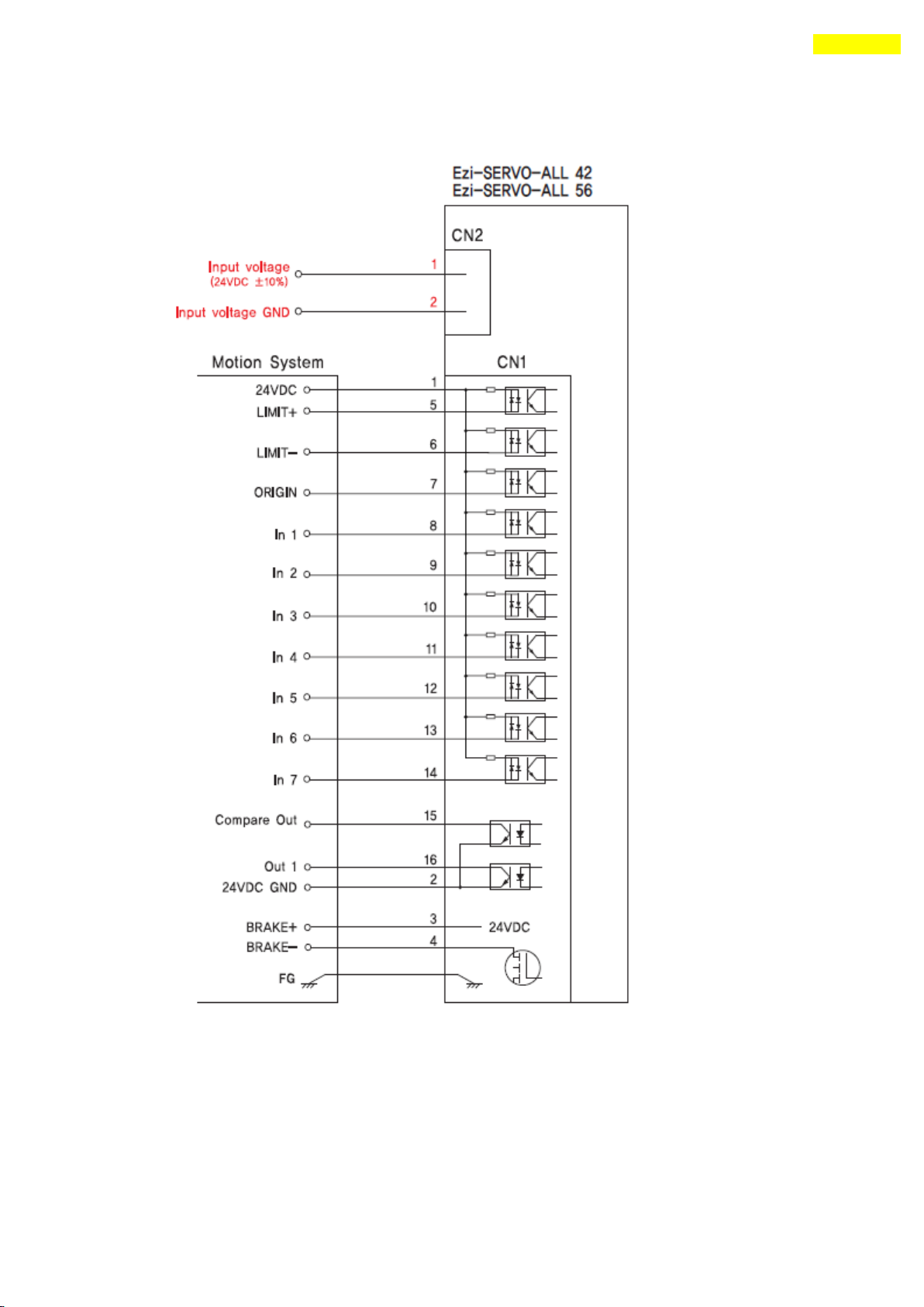
4) Wiring of Ezi-SERVO-ALL42 / Ezi-SERVO-ALL56
www.fastech.co.kr
Page 38
38
5. Configuration of the Controller
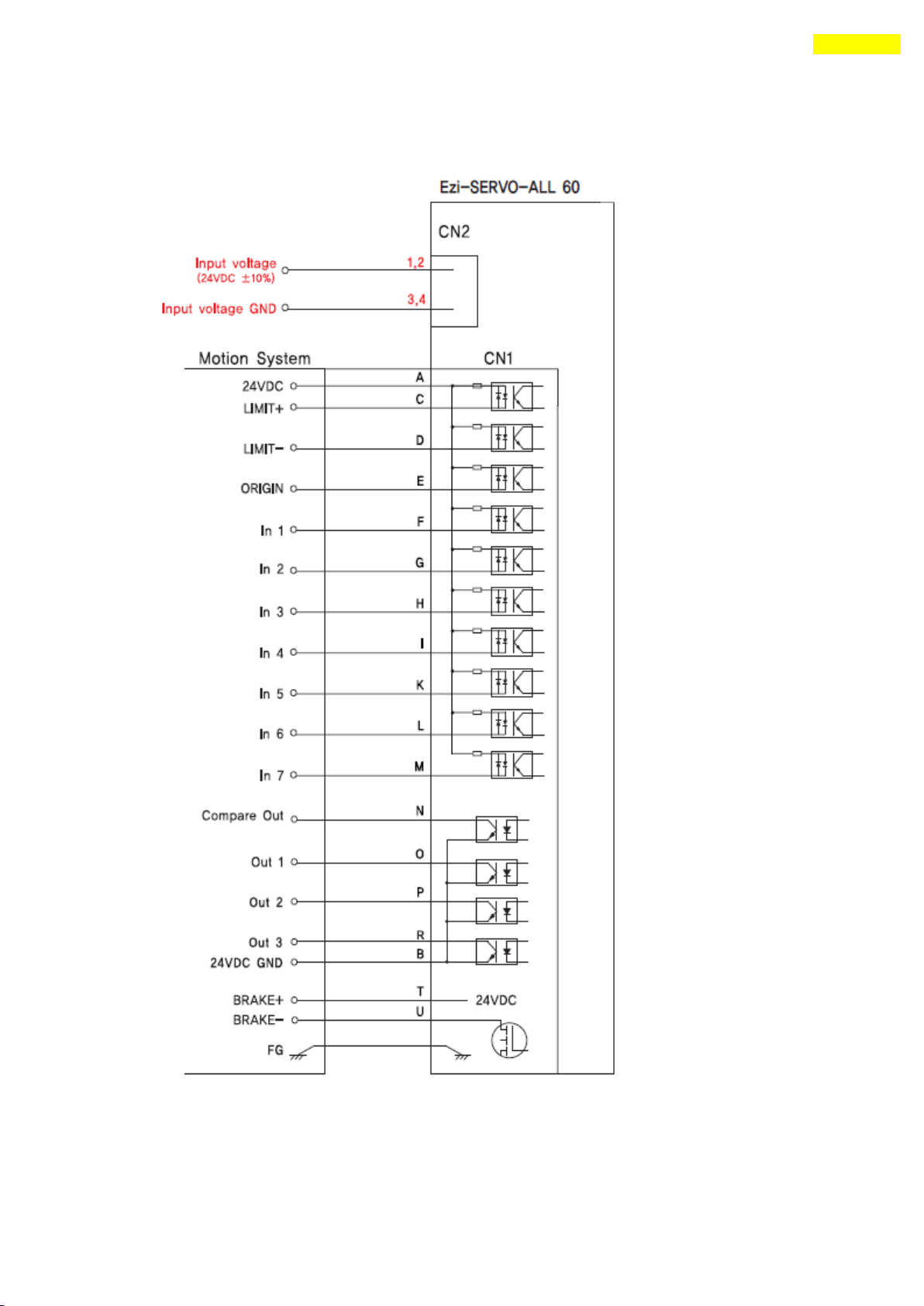
5) Wiring of Ezi-SERVO-ALL60
www.fastech.co.kr
Page 39
39
5. Configuration of the Controller
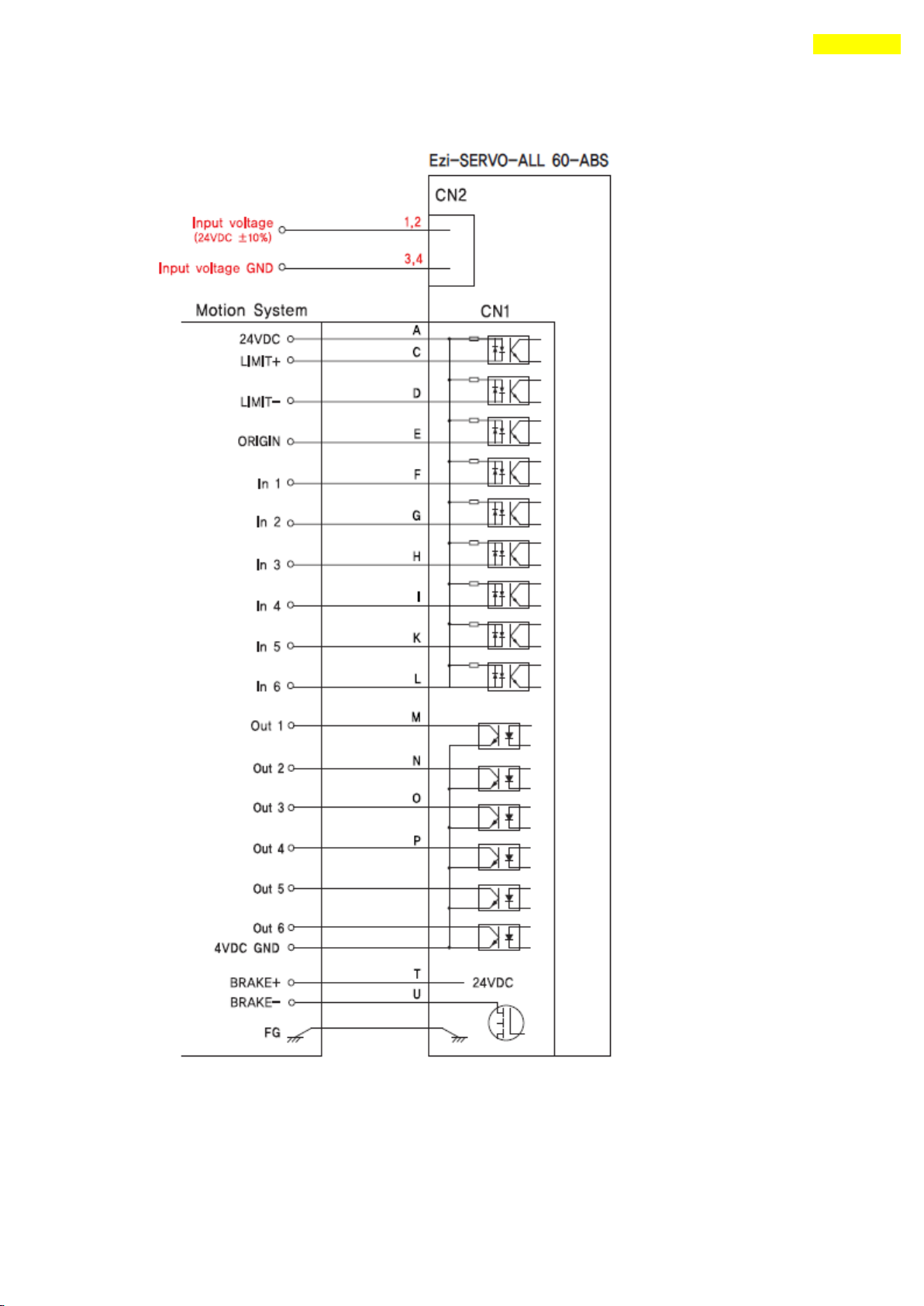
6) Wiring of Ezi-SERVO-ALL60-ABS
www.fastech.co.kr
Page 40
40
6. External Name and Function Setting of Ezi-SERVO-PR
6. External Name and Function Setting of Ezi-SERVO-PR
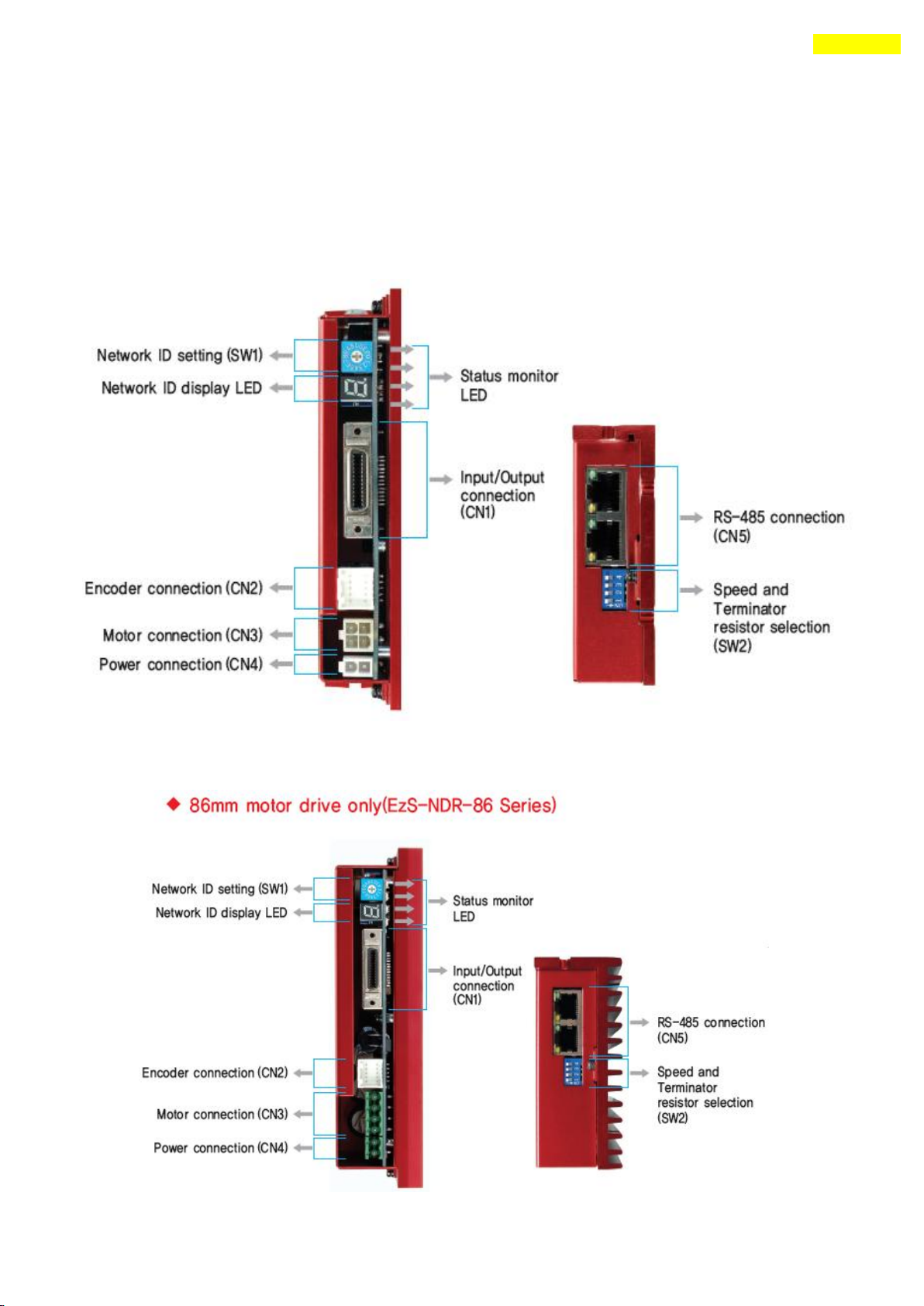
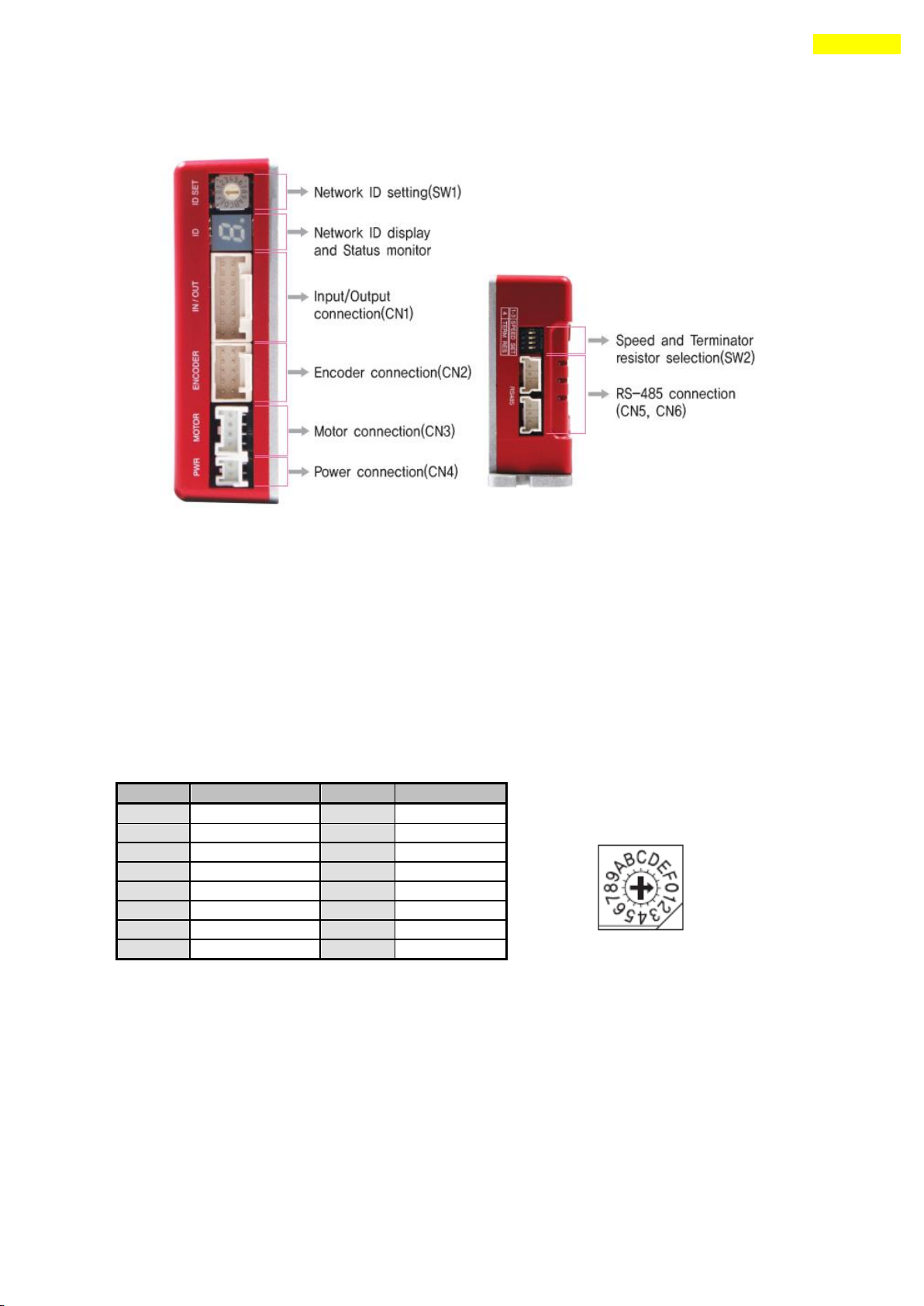
6.1 Appearance and Part Name
1) Ezternal setting of Ezi-SERVO-PR20/ Ezi-SERVO-PR28/ Ezi-SERVO-PR42/ Ezi-SERVO-PR56/
Ezi-SERVO-PR60
2) Ezternal setting of Ezi-SERVO-PR86
www.fastech.co.kr
Page 41
41
6. External Name and Function Setting of Ezi-SERVO-PR
Display
Color
Function
On/Off Condition
① POW
Green
Power input indication
Lights On when power is applied.
② INP
Yellow
Complete Positioning
motion
When position command pulse input and then
the position deviation is within the value
set by the parameter, this lights On.
③ SON
Orange
Servo On/Off indication
Servo On : light On
Servo Off : light Off
④ ALM
Red
Alarm indication
Flash when protective function is
activated.
(If you count LED flash time, you can check
what protective function is run.)
Position
ID No.
Position
ID No. 0 0 8 8 1 1 9 9
2 2 A
10 3 3 B 11 4 4 C 12
5 5 D
13 6 6 E 14
7 7 F
15
The communication speed of drive modules connected to one segment must
be set with same value.
Support max. 115200[bps] when using RS-232 to RS-485 conveter.
SW2.1
SW2.2
SW2.3
SW2.4
Baud rate
[bps]
*1 : default setting value.
.
SW2.1 is OFF.: Terminal resistance is Off.
SW2.1 is ON. : Terminal resistance is On.
X
OFF
OFF
OFF
9600
X
ON
OFF
OFF
19200
X
OFF
ON
OFF
38400
X
ON
ON
OFF
57600
X
OFF
OFF
ON
115200 *1
X
ON
OFF
ON
230400
X
OFF
ON
ON
460800
X
ON
ON
ON
921600
Caution
Caution
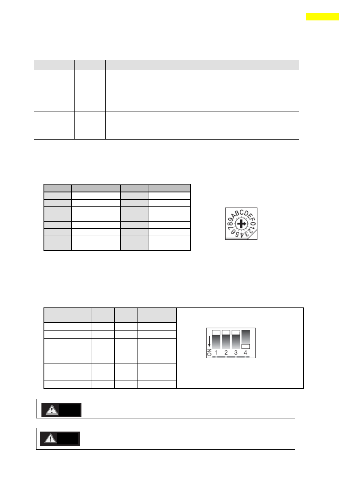
6.2 Status Display LED
6.3 Drive ID Switch Selection (SW1)
1) When several modules are connected to one daisy chain network, this switch is to set
intrinsic ID to each module.
2) The switch can set intrinsic ID to each module up to 16 numbers from 0 to F(15).
6.4 Communication Speed and Terminal Resistance Select Switch(SW2)
SW2 is to set the communication speed between central controller(PC) and Drive. If
corresponding drive module is connected to the end of one network segment, SW2 sets whether
terminal resistance is used. SW2.1 is to set the use of terminal resistance, and SW2.2~SW2.4
is to set the communication speed as follows.
www.fastech.co.kr
Page 42
42
6. External Name and Function Setting of Ezi-SERVO-PR
No.
Function
1
A Phase
2
B Phase
3
/A Phase
4
/B Phase
No.
Function
1
A+
2
A- 3 B+
4
B-
5
Z+ 6 Z-
7
5VDC
8
5VDC GND
9
Frame GND
10
Frame GND
Connect the Brake (current consumption is under 200[mA]) for pin 24.
Refer to 8.4 Output signal for the Brake that is over 200[mA].
No.
Function
1
/B Phase
2
B Phase
3
/A Phase
4
A Phase
No.
Function
1
Power input : 24VDC ± 10%
2
Power input : GND
No.
Function
1
Power input : GND
2
Power input : 40~70VDC
Caution
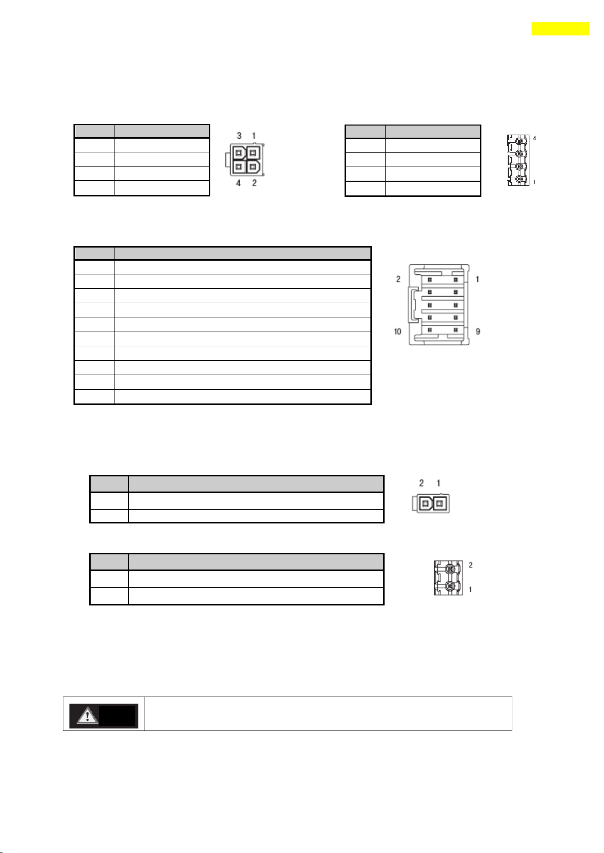
6.5 Motor Connection (CN3)
Motor connector
(Connector Type : Molex 5569-04A2) (86mm)
6.6 Encoder Connection (CN2)
Encoder connector (Connector Type : Molex 55959-1030)
To setup connected encoder resolution, refer to 「13 Parameter」.
6.7 Power Connection(CN4)
Power supply connector (Connector Type : Molex 5569-02A2)
(86mm : PTR AK950-2 )
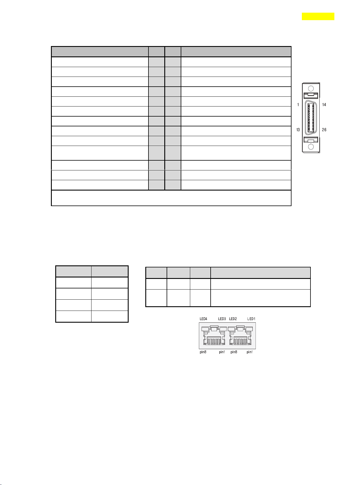
6.8 I/O
Signal Connection (CN1)
Input/output signal connector (Connector Type : 3M 10226-5A2JL)
The programmable input/output pin is set by using user program(GUI) or DLL library.
www.fastech.co.kr
Page 43
43
6. External Name and Function Setting of Ezi-SERVO-PR
Function
No
No
Function
LIMIT+ (Dedicated Input)
1
14
Digital In2 ( Programmable Input)
LIMIT- (Dedicated Input)
2
15
Digital In3 ( Programmable Input)
ORIGIN (Dedicated Input)
3
16
Digital In4 ( Programmable Input)
Digital In1 (Programmable Input)
4
17
Digital In5 ( Programmable Input)
Digital In6 (Programmable Input)
5
18
Digital In8 ( Programmable Input)
Digital In7 (Programmable Input)
6
19
Digital In9 ( Programmable Input)
Compare Out/COMP (Dedicated Output)
7
20
Digital Out7 ( Programmable Output)
Digital Out1 (Programmable Output)
8
21
Digital Out8 ( Programmable Output)
Digital Out2 (Programmable Output)
9
22
Digital Out9 ( Programmable Output)
Digital Out3 (Programmable Output)
10
23
+24V for Brake system(Output)
Digital Out4 (Programmable Output)
11
24
Control signal of Brake system(Output)
Digital Out5 (Programmable Output)
12
25
GND external(Input)
Digital Out6 (Programmable Output)
13
26
+24V external(Input)
* This connector fixed pin is connected to frame GND through a mount hall.
Pin No.
Function
1,2,4,5,7,8
GND
3
Data+
6
Data-
case
Frame GND
LED No.
Display
Color
Lighting Condition
1,3
RUN
Green
Flash when CPU in the drive operates
2,4
COMM
Yellow
Flash when this communicates with the
upper controller
6.9 Communication Connecttion (CN5)
Connector Type : RJ45
Cable Type : UTP/STP CAT5E
www.fastech.co.kr
Page 44
44
7. External Name and Function Setting of Ezi-SERVO-PR-MI
Position
ID No.
Position
ID No. 0 0 8 8
1 1 9 9 2 2 A
10 3 3 B 11
4 4 C
12 5 5 D 13 6 6 E 14
7 7 F
15
7. External Name and Function Setting of Ezi-SERVO-PR-MI
7.1 Appearance and Part Name
7.2 Drive ID Switch Selection (SW1) and 7-segmant
1) When several modules are connected to one daisy chain network, this switch is to set
intrinsic ID to each module.
2) The switch can set intrinsic ID to each module up to 16 numbers from 0 to F(15).
3) 7-segmant of status monitor is display the ID number in normal status, but in
alarm status it display the protection number by flash times.
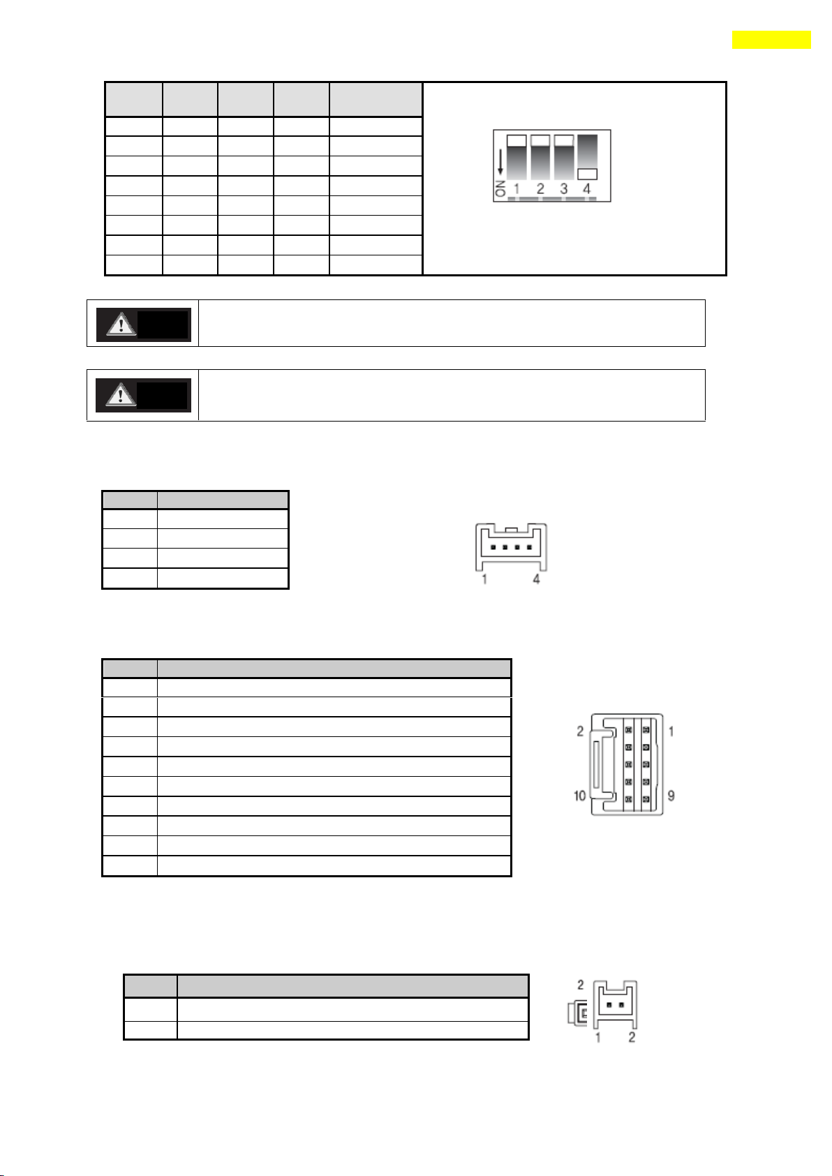
7.3 Communication Speed and Terminal Resistance Select Switch(SW2)
SW2 is to set the communication speed between central controller(PC) and Drive. If
corresponding drive module is connected to the end of one network segment, SW2 sets whether
terminal resistance is used. SW2.1 is to set the use of terminal resistance, and SW2.2~SW2.4
is to set the communication speed as follows.
www.fastech.co.kr
Page 45
45
7. External Name and Function Setting of Ezi-SERVO-PR-MI
The communication speed of drive modules connected to one segment must
be set with same value.
Support max. 115200[bps] when using RS-232 to RS-485 conveter
No.
Function
1
B Phase
2
A Phase
3
/A Phase
4
/B Phase
No.
Function
1
A+
2
A-
3
B+ 4 B-
5
Z+
6
Z- 7 5VDC
8
5VDC GND
9
Frame GND
10
Frame GND
SW2.1
SW2.2
SW2.3
SW2.4
Baud rate
[bps]
*1 : default setting value.
.
SW2.1 is OFF.: Terminal resistance is Off.
SW2.1 is ON. : Terminal resistance is On.
X
OFF
OFF
OFF
9600
X
ON
OFF
OFF
19200
X
OFF
ON
OFF
38400
X
ON
ON
OFF
57600
X
OFF
OFF
ON
115200 *1
X
ON
OFF
ON
230400
X
OFF
ON
ON
460800
X
ON
ON
ON
921600
No.
Function
1
Power input : 24VDC ± 10%
2
Power input : GND
Caution
Caution
7.4 Motor Connection (CN3)
7.5 Encoder Connection (CN2)
To setup connected encoder resolution, refer to 「13 Parameter」.
7.6 Power Connection(CN4)
www.fastech.co.kr
Page 46
46
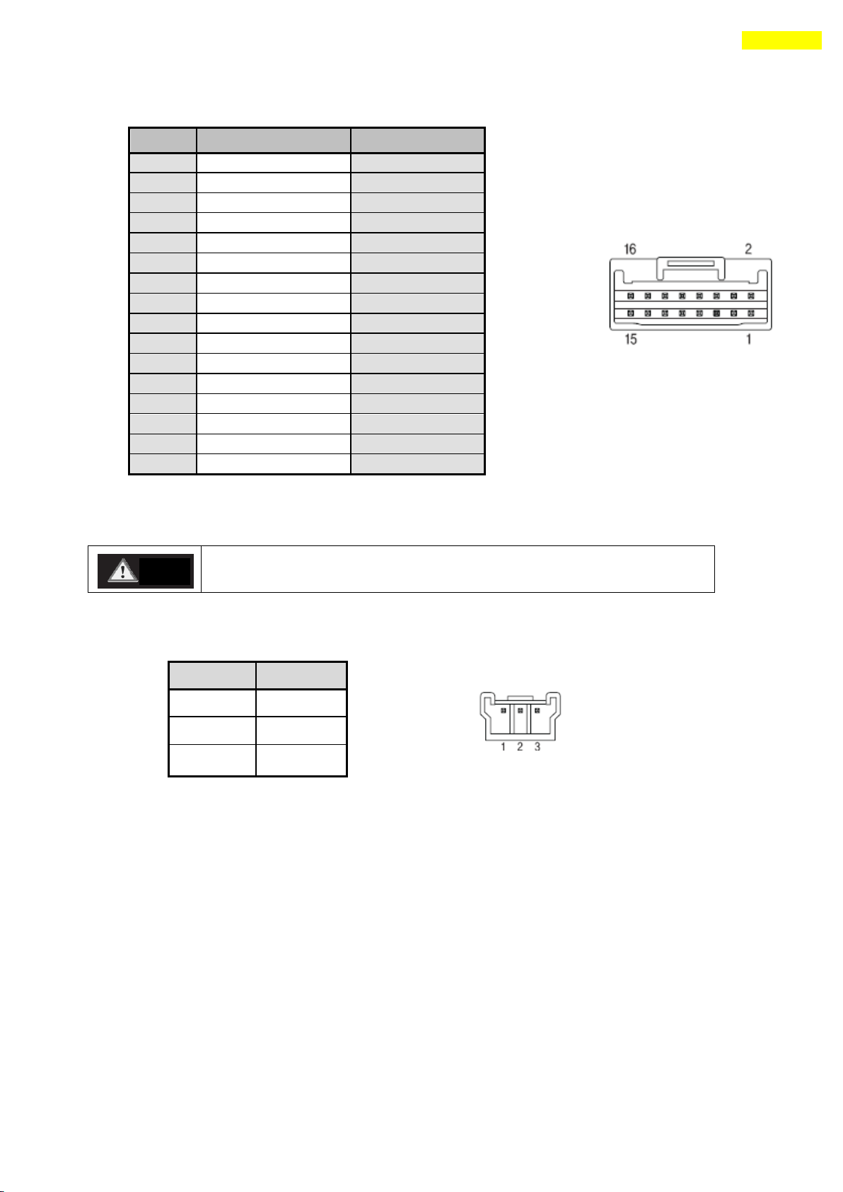
7. External Name and Function Setting of Ezi-SERVO-PR-MI
No.
Function
Input/Output
1
24VDC
Input
2
24VDC GND
Input
3
BRAKE+
Output
4
BRAKE-
Output
5
+Limit sensor
Input
6
-Limit sensor
Input
7
Origin sensor
Input
8
Digital IN1
Input
9
Digital IN2
Input
10
Digital IN3
Input
11
Digital IN4
Input
12
Digital IN5
Input
13
Digital IN6
Input
14
Digital IN7
Input
15
Compare Out (COMP)
Output
16
Digital OUT1
Output
Connect the Brake (current consumption is under 200[mA]) for pin 24.
Refer to 8.4 Output signal for the Brake that is over 200[mA].
No.
Function
1
Data+
2
Data-
3
GND
Caution
7.7 I/O Signal Connection (CN1)
The programmable input/output pin is set by using user program(GUI) or DLL library.
7.8 Communication Connection (CN5)
www.fastech.co.kr
Page 47
47
8. External Name and Function Setting of Ezi-SERVO-ALL42 / ALL56
8. External Name and Function Setting of Ezi-SERVO-ALL42 / ALL56
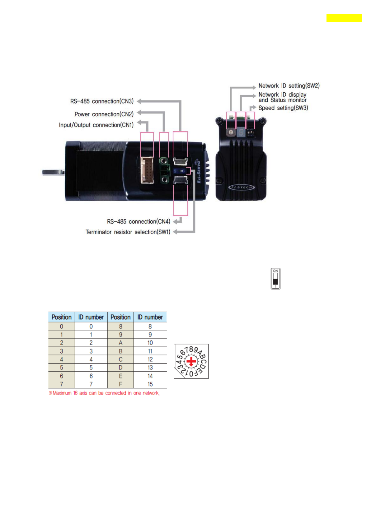
8.1 Appearance and Part Name
8.2 Terminal Resistance Select Switch(SW1)
Terminator resistor selection switch under RS-485 communication.
Please set ON for Terminator Controller of Network.
8.3 Drive ID Switch Selection (SW2)
8.4 Communication Speed Select Switch(SW3)
www.fastech.co.kr
Page 48
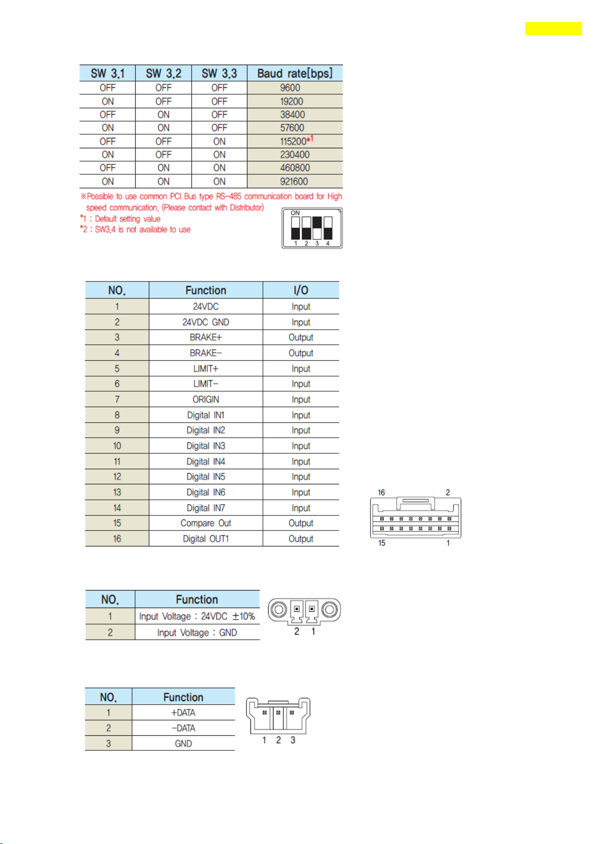
48
8. External Name and Function Setting of Ezi-SERVO-ALL42 / ALL56
8.5 I/O Signal Connection (CN1)
8.6 Power Connection(CN2)
8.7 Communication Connection (CN3, CN4)
www.fastech.co.kr
Page 49
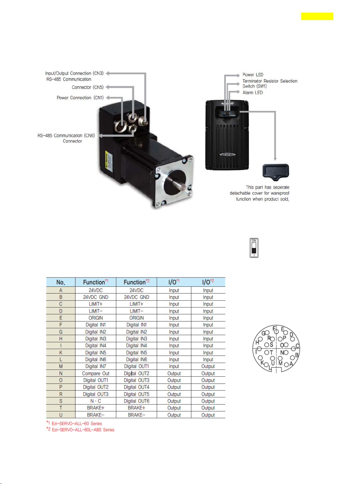
49
9. External Name and Function Setting of Ezi-SERVO-ALL60
9. External Name and Function Setting of Ezi-SERVO-ALL60
9.1 Appearance and Part Name
9.2 Terminal Resistance Select Switch(SW1)
Terminator resistor selection switch under RS-485 communication.
Please set ON for Terminator Controller of Network.
9.3 I/O Signal Connection (CN3)
www.fastech.co.kr
Page 50
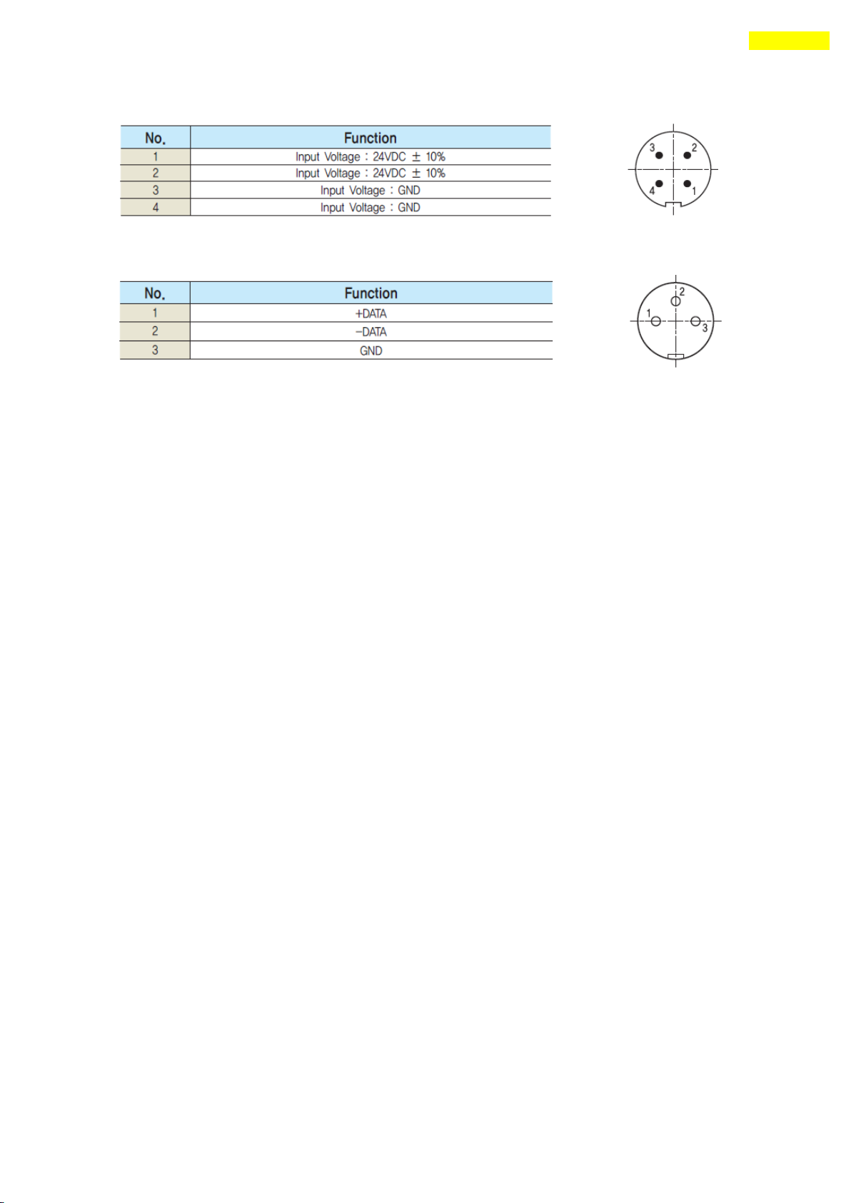
50
9.4 Power Connection(CN1)
9.5 Communication Connection (CN5, CN6)
www.fastech.co.kr
Page 51
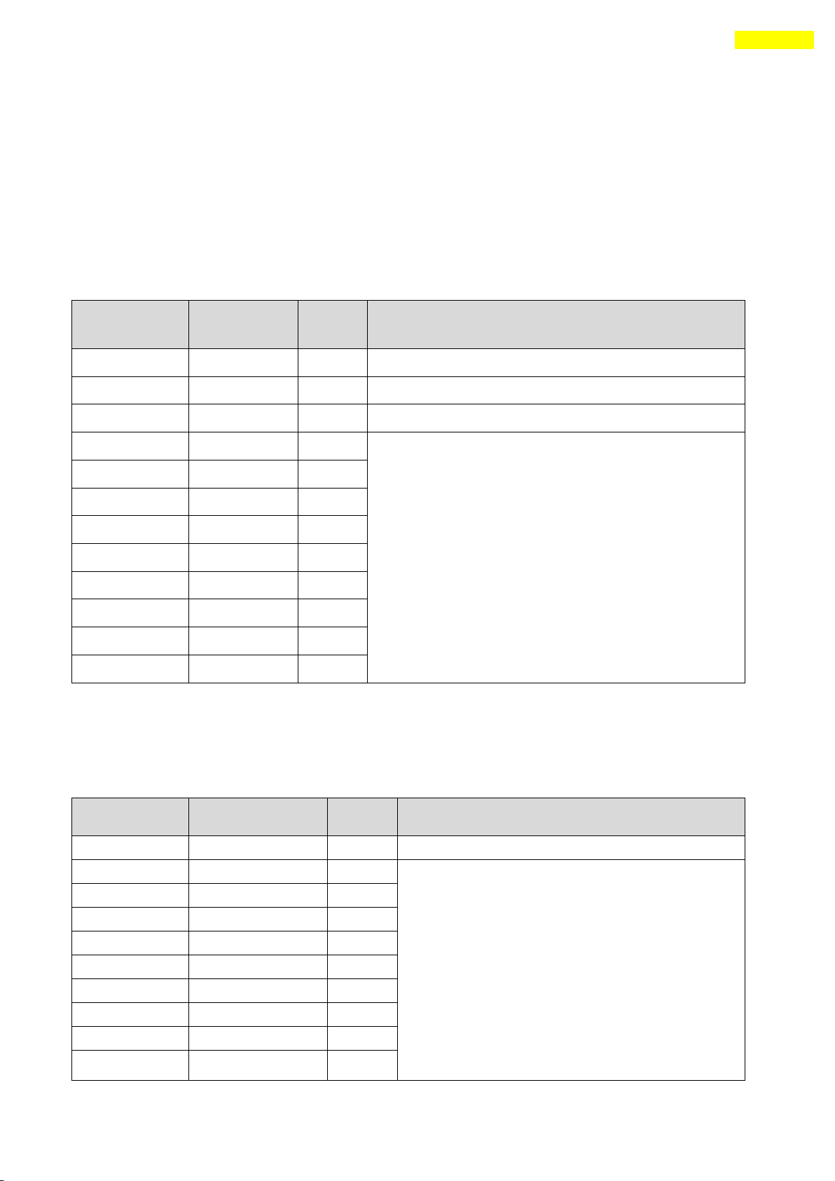
51
10. Control I/O Signal
Ezi-SERVO-PR
CN1 No.
Ezi-SERVO-PR-
MI
CN1 No.
Signal
Name
Function
1
5
Limit+
Positive limit sensor signal
2
6
Limit-
Negative limit sensor signal
3
7
Origin
Origin sensor signal
4
8
IN1
Clear Pos
Position table A0 ~ Position table A7 (PT A0~PT A7)
Position table start execution (PT Start)
Soft Stop(Stop)
Jog+
JogAlarmReset
ServoON
Pause
Origin Search
Teaching
Emergency Stop(E-Stop)
Jump Position Table input 0 ~ Jump Position Table input 2
(JPT IN 0~ JPT IN 2)
Jump Position Table start (JPT Start)
User input 0 ~ User input 8 (User IN 0 ~ User IN 8)
14
9
IN2
15
10
IN3
16
11
IN4
17
12
IN5
5
13
IN6
6
14
IN7
18
None
IN8
19
None
IN9
Ezi-SERVO-PR
CN1 No.
Ezi-SERVO-PR-MI
CN1 No.
Signal
Name
Function
7
15
COMP
Specific output signal (Compare Out)
8
16
OUT1
InPosition
Alarm
Moving
Acc/Dec
ACK
END
AlarmBlink
OriginSearchOK
ServoReady
Brake
Position Table output 0 ~ Position Table output 2
(PT OUT 0 ~ PT OUT 2)
User Output 0 ~ User Output 8
9
None
OUT2
10
None
OUT3
11
None
OUT4
12
None
OUT5
13
None
OUT6
20
None
OUT7
21
None
OUT8
22
None
OUT9
10. Control I/O Signal
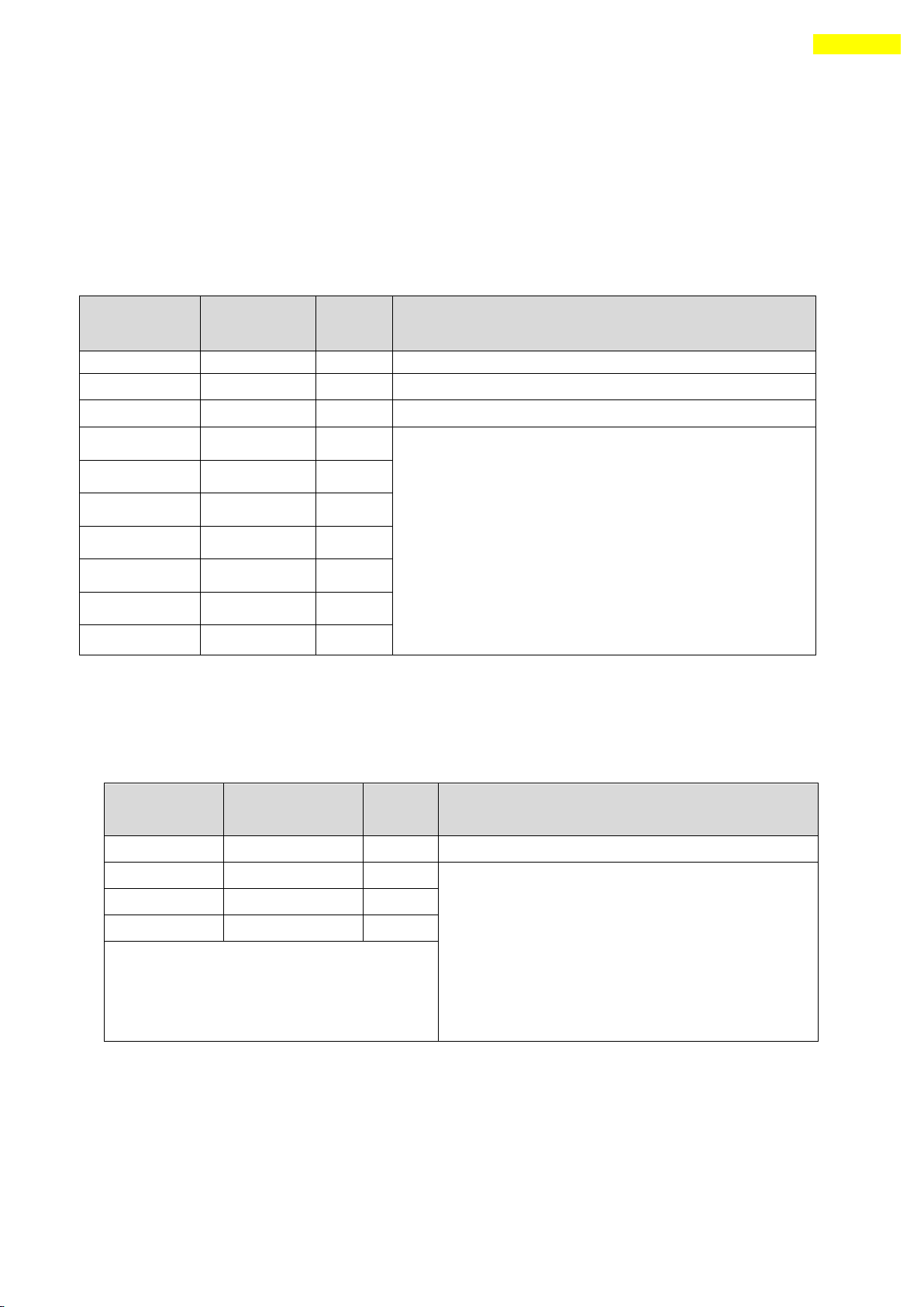
10.1 Signal Cabling (Ezi-SERVO-PR type)
All control I/O signals use connector CN1 as specified below.
1) Input : 「Limit+」, 「Limit-」, 「Origin」 signals are fixed to CN1 No. 1,2,3.
Other signals as like ‘Clear Pos’are assigned to IN1~IN9 terminal blocks.
(3 dedicated input + 9 programmable input = total 12 input pins.)
Ezi-SRERVO-PR : 3 dedicated In + 9 programmable In = 12 Inputs
Ezi-SRERVO-PR-MI : 3 dedicated In + 7 programmable In = 10 Inputs
2) Output : 「COMP」 signal is dedicated to CN1 No.7. Other signals like
Inposition are assigned to OUT1~OUT9 terminal blocks.
Ezi-SRERVO-PR : 1 dedicated Out + 9 programmable Out = 10 Outputs
Ezi-SRERVO-PR-MI : 1 dedicated Out + 1 programmable Out = 2 Outputs
www.fastech.co.kr
Page 52
52
10. Control I/O Signal
Ezi-SERVO-ALL
42/ALL56
CN1 No.
Ezi-SERVO-ALL60
CN1 No.
Signal
Name
Function
15
N
COMP
Specific output signal (Compare Out)
16
O
OUT1
InPosition, Moving
Alarm, Acc/Dec
ACK, END
AlarmBlnk
OriginSearchOK
ServoReady, Brake
Position Table output 0 ~ Position Table
output 2
(PT OUT 0 ~ PT OUT 2)
User Output 0 ~ User Output 8
None
P
OUT2
None
R
OUT3
Ezi-SERVO-ALL
42/ALL56
CN1 No.
Ezi-SERVO-
ALL60
CN1 No.
Signal
Name
Function
5
C
Limit+
Positive limit sensor signal
6
D
Limit-
Negative limit sensor signal
7
E
Origin
Origin sensor signal
8
F
IN1
ClearPos
Position Table A0 ~ Position Table A7 (PT A0~PT A7)
Position Table start execution (PT Start)
Soft Stop(Stop) Emergency Stop(E-Stop)
Jog+, JogAlarmReset, ServoON
OriginSearch
Teaching, Pause
Jump Position Table input 0 ~ Jump Position Table
input 2
(JPT IN 0~ JPT IN 2)
Jump Position Table start (JPT Start)
User input 0 ~ User input 8 (User IN 0 ~ User IN 8)
9
G
IN2
10
H
IN3
11
I
IN4
12
K
IN5
13
L
IN6
14
M
IN7
10.2 Signal Cabling (Ezi-SERVO-ALL type)
All control I/O signals use connector CN1 as specified below.
1) Input : 「Limit+」, 「Limit-」, 「Origin」 signals are fixed to CN1 No. 1,2,3.
Other signals as like ‘Clear Pos’are assigned to IN1~IN7 terminal blocks.
(3 dedicated input + 9 programmable input = total 12 input pins.)
Ezi-SRERVO-ALL42 / ALL56 : 3 dedicated In + 7 programmable In = 10 Inputs
Ezi-SRERVO-ALL60 : 3 dedicated In + 7 programmable In = 10 Inputs
2) Output : 「COMP」 signal is dedicated to CN1 No.7. Other signals like
Inposition are assigned to OUT1~OUT9 terminal blocks.
Ezi-SRERVO- ALL42/ALL56 : 1 dedicated Out + 1 programmable Out = 2 Outputs
Ezi-SRERVO-ALL60 : 1 dedicated Out + 3 programmable Out = 4 Outputs
www.fastech.co.kr
Page 53
53
10. Control I/O Signal
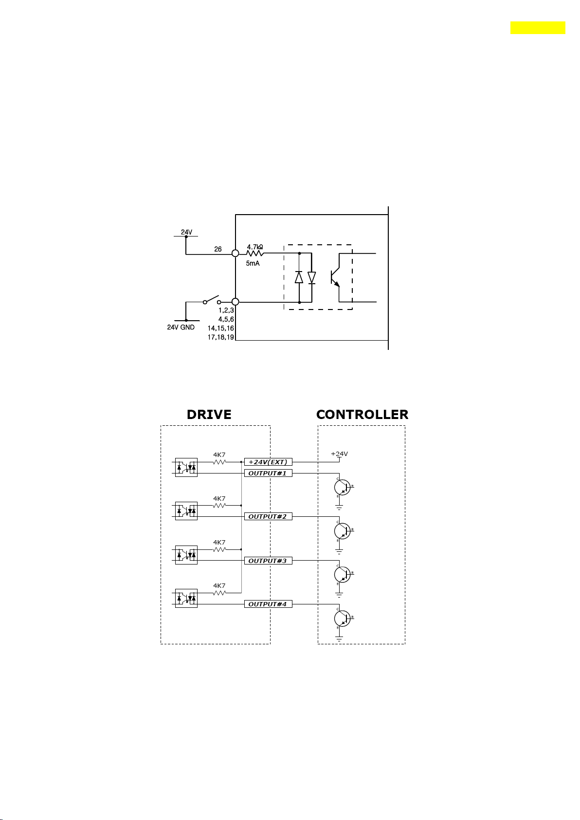
10.3Connection Circuit
All drive I/O signals are insulated by a photocoupler. The signals display the internal
photocoupler status - [ON: Conduction] and [OFF: Non- Conduction], not the signal voltage
level.
1) Input Circuit
Input circuit power of DC24V±10% (consumed current : about 5mA/circuit) should be
separately prepared.
Connect NPN type Input signal
Connect the ‘+24V external’signal of drive to ‘+24V’ of Controller .
www.fastech.co.kr
Page 54
54
10. Control I/O Signal
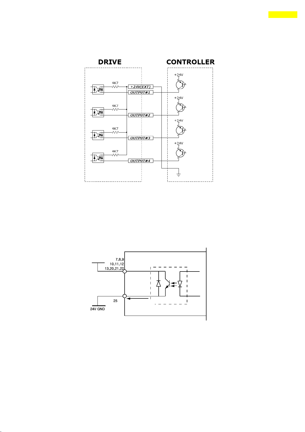
Connect PNP type Input signal
Connect the ‘+24V external’signal of drive to ‘GND’ of Controller .
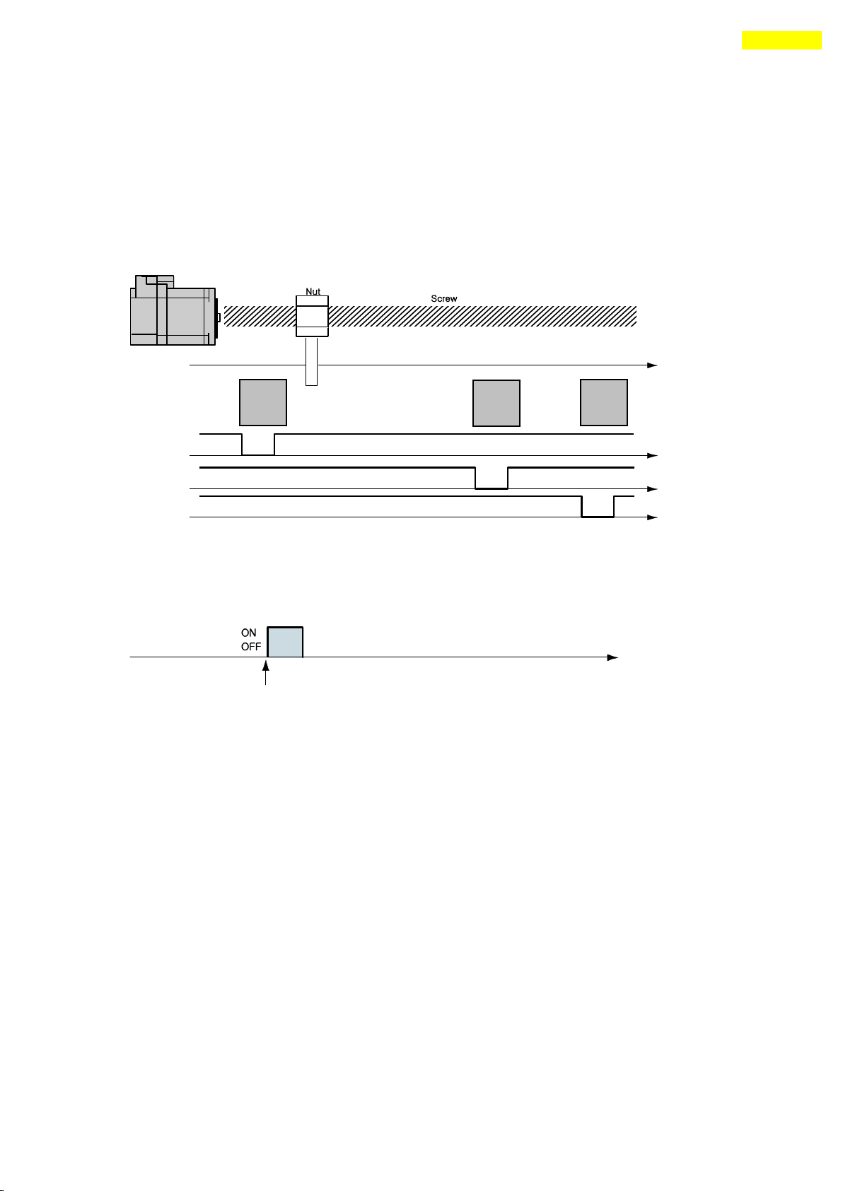
2) Output Circuit
Output circuit power should be separately prepared. This may share input circuit power.
In this case, working power capacity should add output power capacity to input power
capacity.
Applied voltage and power capacity in the control output port are as follows.
·Applied voltage ≤ 30V
·Electrified current ≤ 15mA
www.fastech.co.kr
Page 55
55
10. Control I/O Signal
10.4 Input Signal
1) ‘Limit’ Sensor and ‘Origin’ Sensor
Limit sensor and origin sensor are assigned to LIMIT+, LIMIT- , and ORIGIN pin in the
CN1 connector respectively. LIMIT+ and LIMIT- sensors are used to limit the motion of
each axis clockwise and counterclockwise to prevent mechanical collision. Origin sensor
is to set the origin of equipment.
2) ‘Clear Pos’ Input
This input signal sets the command position and the actual position to 0 in relation to
motion position control. The reset signal pulse scale is 10ms or more.
3) ‘Position Table A0 – A7 (PT A0~A7)’Input
The position table supports the machine so that its motion can be controlled by I/O
signals of central controller. It can directly transmit commands such as position table
number, start/stop and origin return to the machine through the PLC. Also, the user can
check output signals such as in-position, completion of origin return and Servo ready
through the PLC.
「Position Table A0~A7」 inputs are total 8 bits of input signal. It is used to set 256
position table numbers. There are two application methods as follows.
* Ezi-SRERVO-PR-MI / Ezi-SERVO-ALL : maximum 64 position table numbers can be set.
1) To set position table number(0~255) to be set by ‘PT start’ input signal.
2) To set position table number(0~255) to save current position values by ‘Teaching’
input signal.
By using PT A0~A7 signals, the position table address can be set from 0 to 255 with a
www.fastech.co.kr
Page 56
56
10. Control I/O Signal
A7
A6
A5 ~ A3
A2
A1
A0
PT No.
0 0 0
0 0 0 0 0 0 0
0 0 1 1 0 0 0
0 1 0 2 0 0 0
0 1 1 3 … … … … … … … … … … … … … … … … … …
1 1 1
1 1 0
254
1 1 1
1 1 1
255
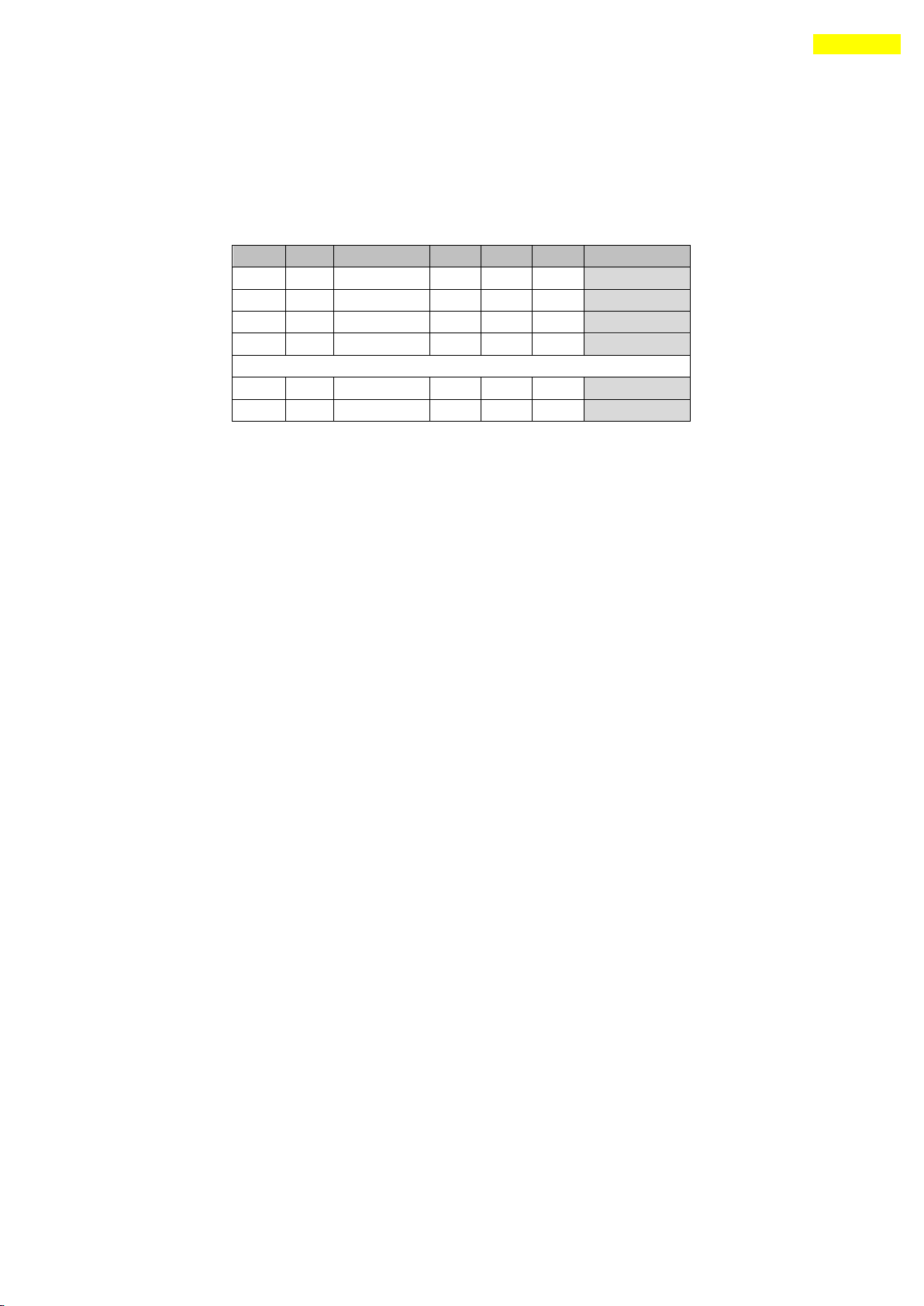
binary number. A0 is least significant bit and A7 is most significant bit. The following
table shows how to assign position table number.
*1. Save signal cabling : If‘PT A0~A7’signal is not connected when motioning by
‘PT Start’signal, the position table number will be ‘0’
*2. ‘PT A5/UserIN 6’ ‘PT A6/UserIN 7’ ‘PT A7/UserIN 8’signal setting :
This signal can be used as‘PT A5~A7’, and also can be used as
‘User IN6~IN8’signal when the input signal ‘User IN0~IN5’is not enough.
4) ‘Position Table Start (PT Start)’Input
By using PT A0~A7 signals, set and input the running PT start number. Then the motion
pattern corresponds to the PT No. will be executed.
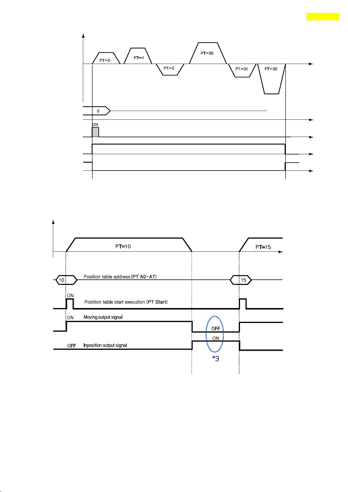
Following example shows that total 6 motion patterns are in order executed from No.0 to
No.32 and then stopped.
1) All of PT A0~A7 is set to ‘0’ and PT number is set to ‘0’.
2) Set PT Start signal to [ON], and PT No.0 motion pattern will be executed.
3) When the motion pattern is started by PT, ACK signal and END signal are displayed to
[ON] at CN1 output port as illustrated below. The signal is kept until one motion
pattern loop is stopped. After all motions are stopped, the output signal level is
set to [OFF].
4) PT Start signal is edge trigger type and pulse scale is 10ms or more.
www.fastech.co.kr
Page 57
57
10. Control I/O Signal
*1. Timing of signals : PT A0~A7 signals must be set before(50msec)
PT Start signal set to [ON].
*2. If the PT A0~A7 signals are not used and the PT Start signal set to [ON],
the PT No. 0 will be executed.
*3. Checking the ‘Moving’ and ‘Inposition’signals :
Between sequencial ‘PT Start’ motion command signal, the checking step
for motion status(Moving, Inposition) is needed before next motion command.
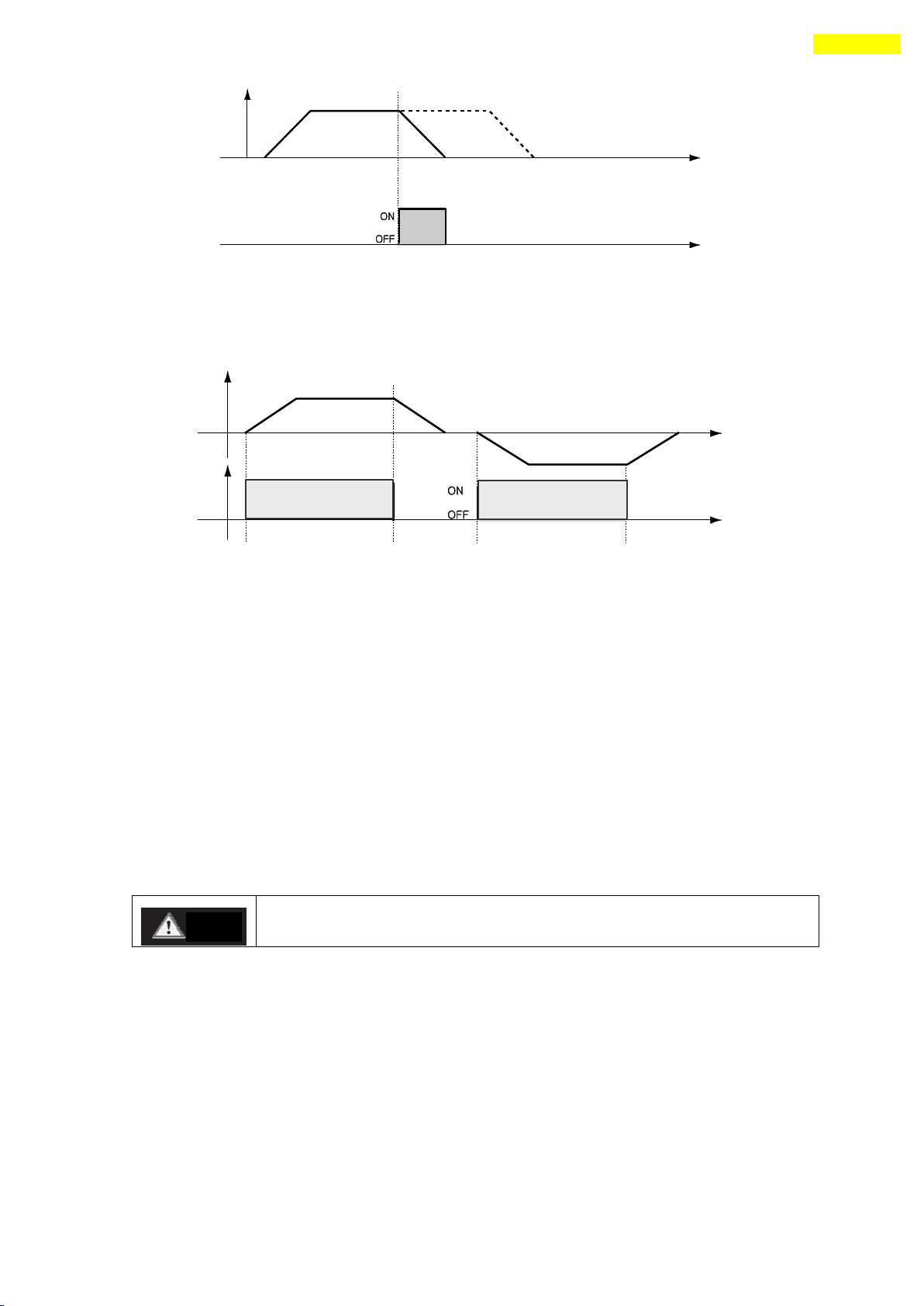
5) ‘Soft Stop’Input
Soft stop input signal is to stop motion patterns under operation. The deceleration
condition until they stop complies with the deceleration time value and the start speed
value set previously. The soft stop signal is active in ON level and pulse scale is 10ms
or more.
www.fastech.co.kr
Page 58
58
10. Control I/O Signal
If the ‘Servo ON’ signal is assigned to input pin, ServoON command
from GUI or DLL library will not executed.
Caution
6) ‘Jog+’ and ‘Jog-‘Input
When Jog+ or Jog- signal is ON, the motor rotates clockwise or counterclockwise until it
reaches the hardware limit or the software limit. Jog motion pattern is subject to jog
related parameters (No.7: start speed, No.6: speed, No.8: Acc Dec time).
7) ‘Servo ON’ and ‘AlarmReset’Input
When the protective function of drive executes, alarm output is released. When
AlarmReset input is set to ON, alarm output and alarm blink output are released. Before
releasing alarm output, the user must remove any cause of alarm operating.
When Servo ON/OFF signal is set to OFF, the drive stops supplying the current to the
motor and so the user can directly adjust the output position. When Servo ON/OFF signal
is set to ON, the drive restarts to supply the current to the motor and its torque is
recovered. Before operating the motor, the user must set it to ON.
When the drive is set to Servo ON, CN1 connector’s ServoReady output signal is
set to ON. Servo ON signal is edge trigger type and pulse scale is 10ms or more.
www.fastech.co.kr
Page 59
59
10. Control I/O Signal
*1. If ‘No.0: Pulse per Revolution’ in the parameter list is changed, the motor is set
to Servo OFF.
*2. After ‘ServoON’ signal is assigned to input pin, it is impossible to use
‘SERVO ON’ button in UserProgram(GUI).
*3. After ‘ServoON’ is executed, the ‘Command Position’value will change as
same as ‘Actual Position’value to remove ‘Position Error’.
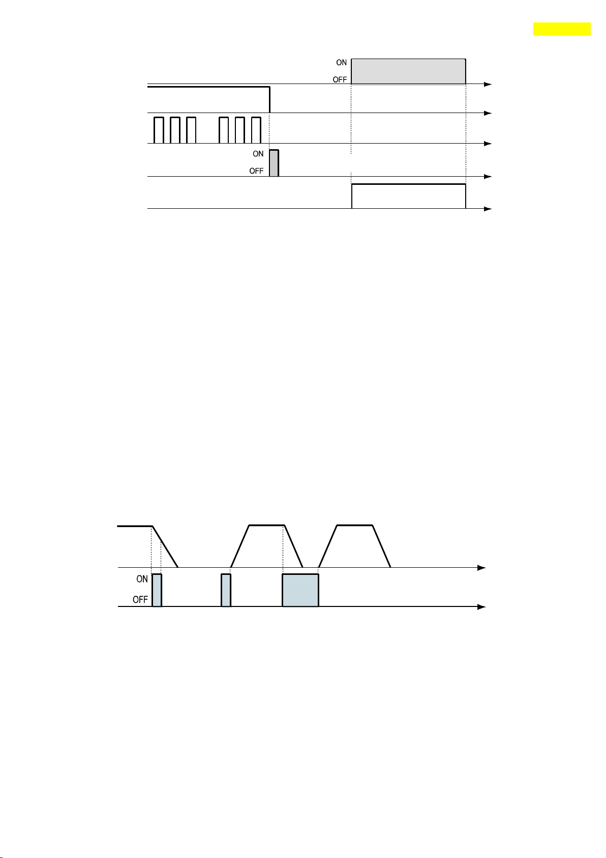
8) ‘Pause’Input
When Pause signal is set to ON, the motion in service is stopped. There are two pause
signal operation modes as follows.
① Case A : When Pause signal is set to ON, the motor starts to decelerate. Pause
signal becomes OFF before the motor is completely stopped. To start motion, Pause
signal should be set to ON.
② Case B : When Pause signal is set to ON, the motor starts to decelerate. The signal
is continuously maintained since the motor is completely stopped. To start motion,
Pause signal should be set to OFF.
Pause signal pulse scale is 10ms or more.
*1. This function is not applied while ‘Repeat Test’ of the User Program(GUI) is
executing.
*2. This function is not applied while ‘Push Motion’ positioning.
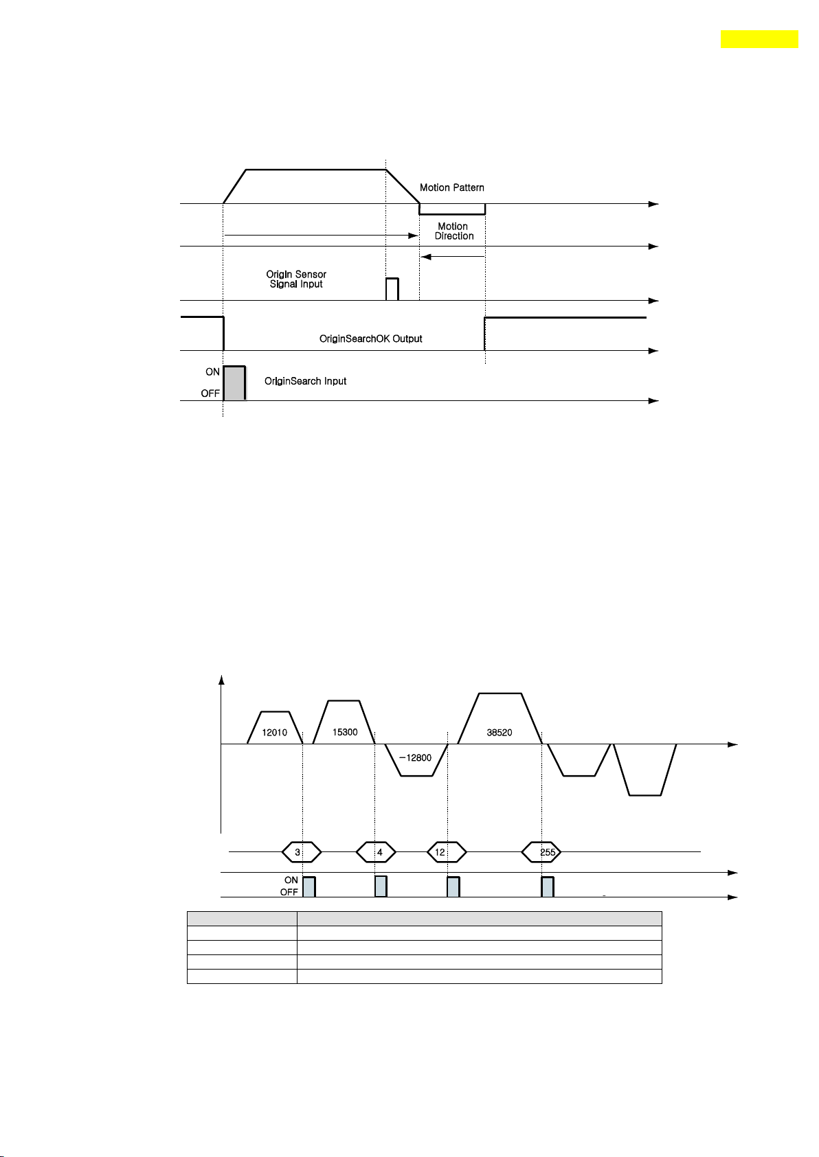
9) ‘Origin Search’Input
When ‘Origin Search’ signal is set to ON (10ms or more), it starts to search the
origin position according to selected conditions. The conditions are subject to
parameters such as No.20:Org Method, No.17:Org Speed, No.18:Org Search Speed, No.19:Org
AccDec Time, No.21:Org Dir. (For more information, refer to ‘15.Parameter’.) When the
www.fastech.co.kr
Page 60
60
10. Control I/O Signal
PT No.
Position Value [pulse] of Corresponding PT
3
12010
4
15300
12
-12800
255
38520
origin search command is completed, ‘Origin Search OK’ signal is set to ON to CN1
connector’s output port.
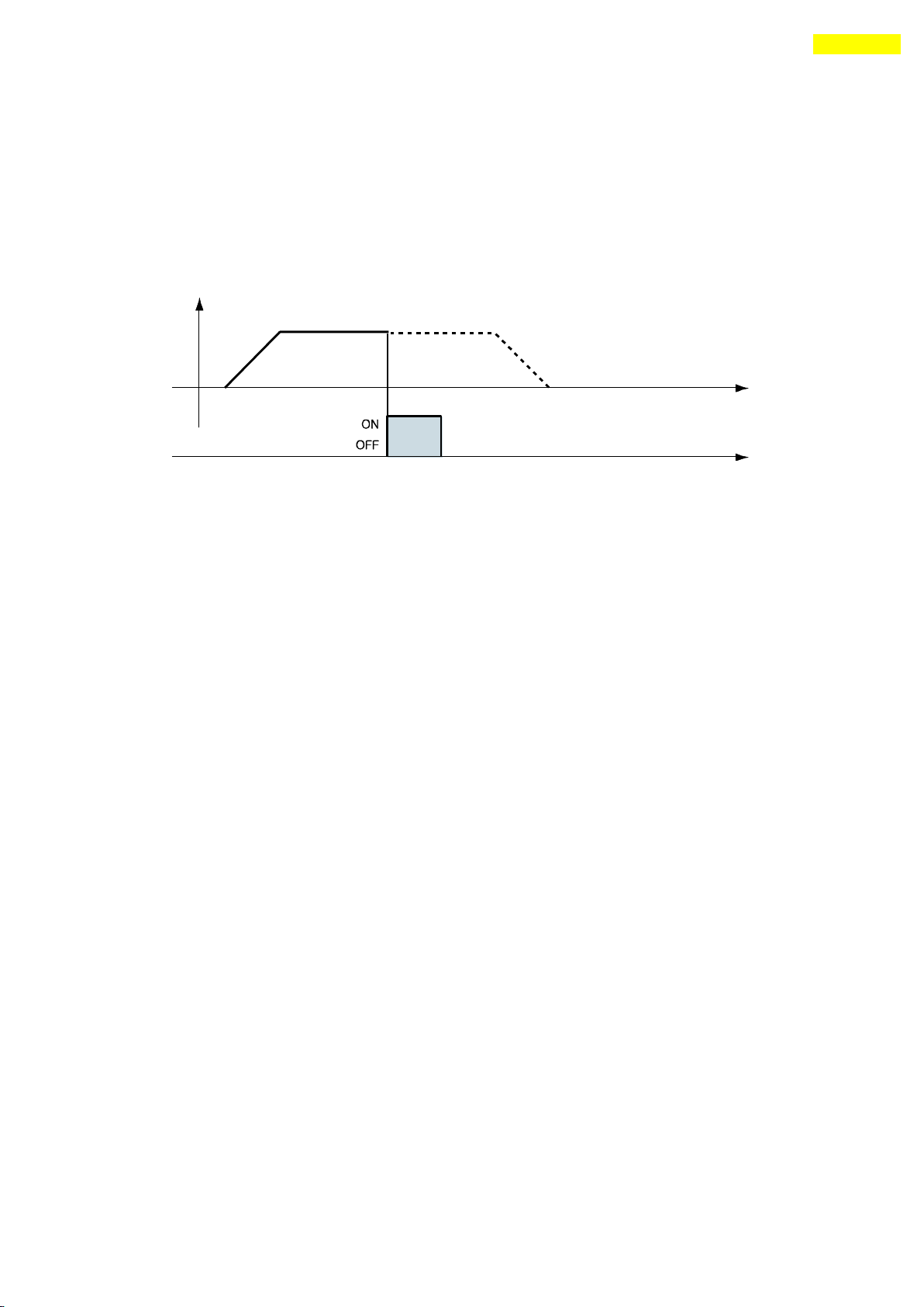
10) ‘Teaching’Input
Teaching signal functions that the position value[pulse] being working can be
automatically inputted into a ‘position’ value of a specific position table. If it is
hard to calculate the exact moving distance(position value) of specific motion
mechanically, the user can measure and set the distance(position value) easily by using
this signal.
1) By using User Program(GUI), set a command type of corresponding PT number among 4
kinds of absolute moving commands(Absolute Move).
2) By using input signal(PT A0~A7), select corresponding PT number.
3) When Teaching signal is set to ON, the position value[pulse] is save to the position
value of corresponding PT. At this time, it becomes the absolute position value.
4) Teaching signal pulse scale is 10ms or more.
* After executing Teaching, click ‘Refresh’ icon, and the position value will be
displayed to the position table.
* Click ‘Save to ROM’ icon, and the position value will be saved to the ROM area.
www.fastech.co.kr
Page 61
61
10. Control I/O Signal
* Teaching signal can be used by two methods; the user assigns actual signal to the
motor, or he clicks ‘Teaching’ icon at the ‘I/O Monitoring’ window of User
Program(GUI).
11) ‘E-Stop’Input
When ‘Emergency stop’ signal is set to ON, the current motion is stopped immediately
without deceleration. E-Stop signal is active in ON level and pulse scale is 10ms or
more.
www.fastech.co.kr
Page 62
62
10. Control I/O Signal
PT No.
…
JP Table No.
JPT 0
JPT 1
JPT 2
14 … 15
115
116
225
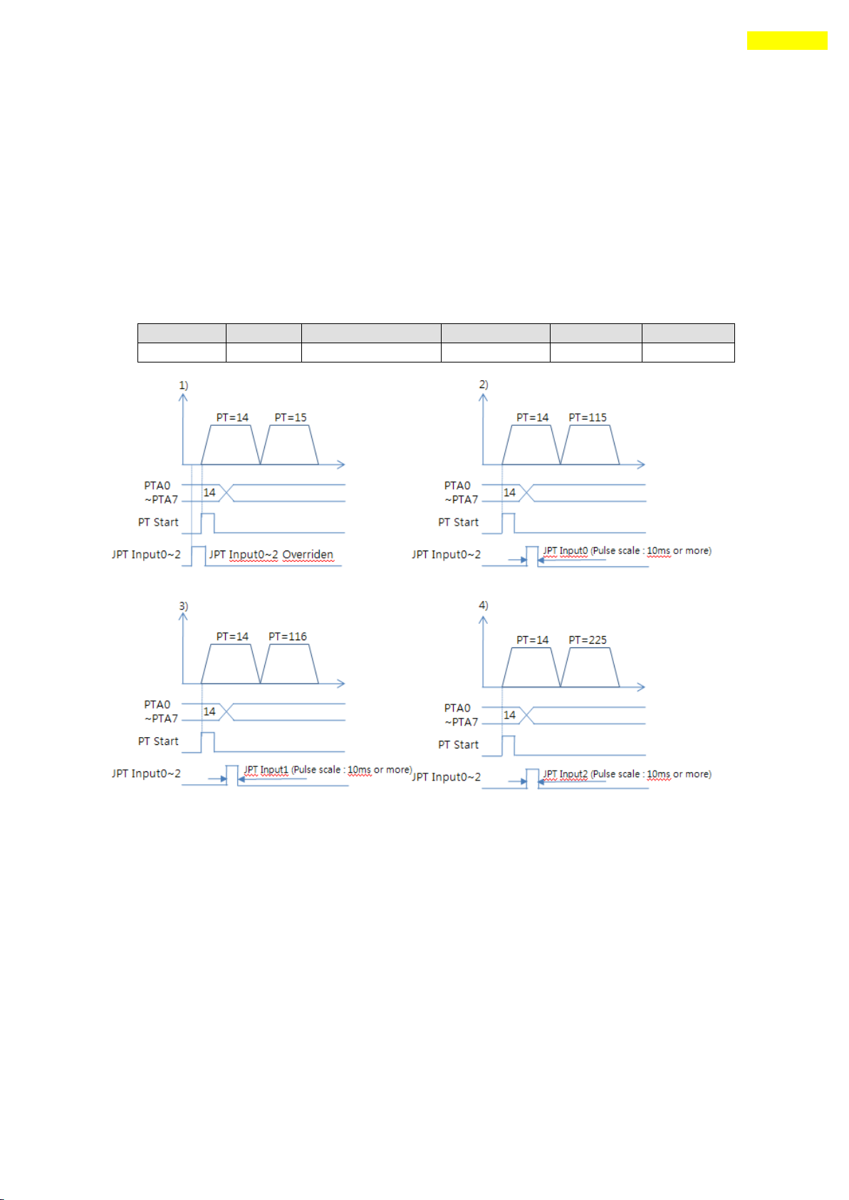
12) ‘JPT Input0~Input2 (Jump Position Table Input)’Input
Select motion pattern(position table number) to be subsequently executed according to
input signal conditions.
【Example】 If PT 14 motion operates, when there is no other input signal, next motion
becomes PT 15 as shown in Figure 1). However, if ‘JPT Input0~Input2’ input signal is
set to ON while PT 14 is executing, each corresponding position number is executed as
shown in Figure 2)~4).
PT 14 Data
www.fastech.co.kr
Page 63
63
10. Control I/O Signal
PT No.
…
Wait Time
JP Table No
JPT 0
JPT 1
JPT 2
14 … 500
10015
10115
10116
10255
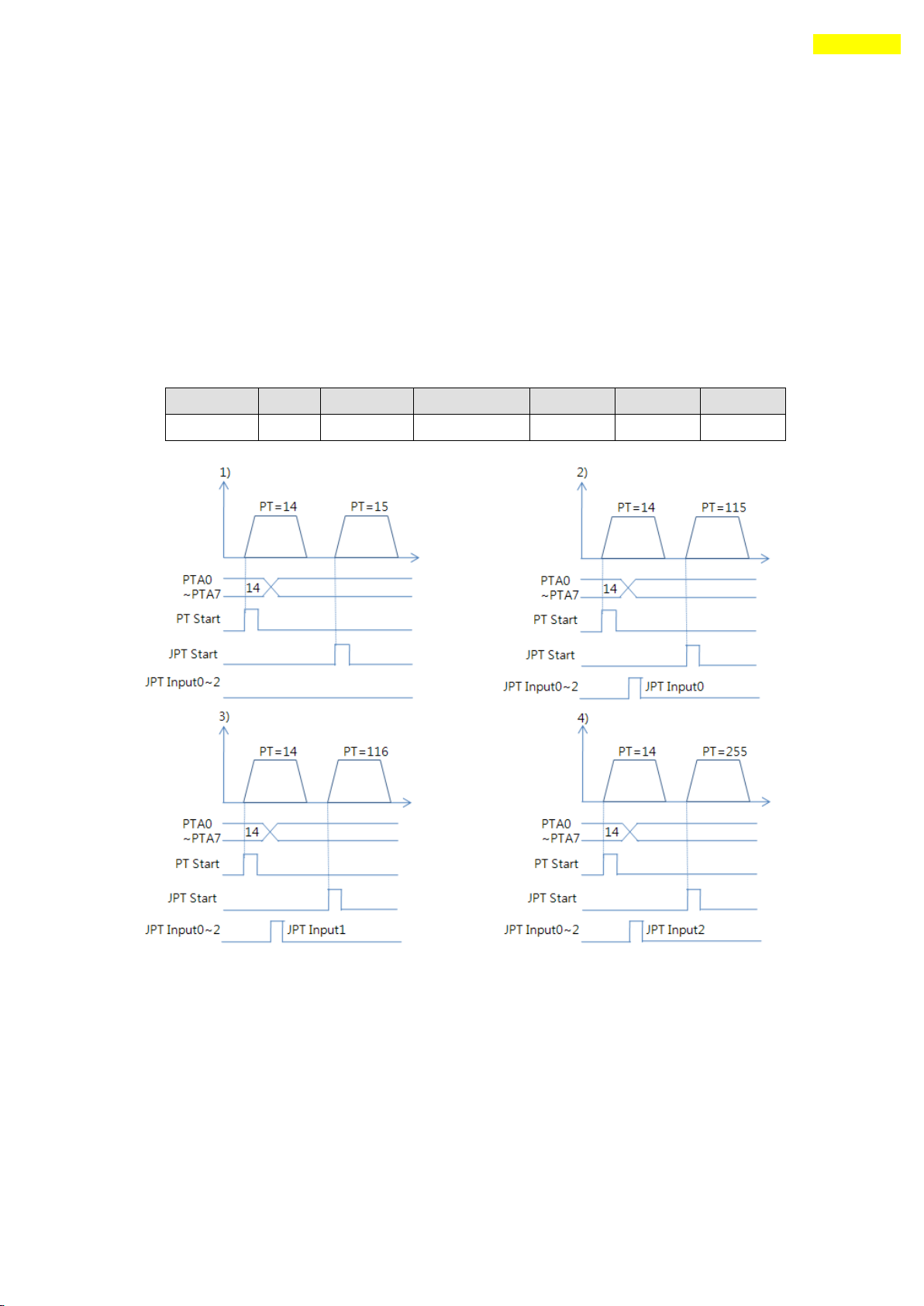
13) ‘JPT(Jump Position Table) Start’Input
To select motion pattern(position table number) to be subsequently executed according to
input signal conditions. The difference from Paragraph 「13) ‘JPT Input0~Input2 Input」
is:
1) PT number to be jumped must be composed to 10XXX;
2) Next motion is not executed until ‘JPT Start’ is set to ON. If ‘Wait Time’ value
of PT data is more than ‘0’, the time lapses additionally and then next motion is
executed.
【Example】
PT 14 Data
www.fastech.co.kr
Page 64
64
10. Control I/O Signal
Value
Mode
Description
0~7
Fast mode
Output the signal in 1[msec] after the motor stop
in target position.
8~15
Accurate mode
Output the signal in maximum 100[msec] after the
motor stop in target position.
(Time is needed to check find exact positioning)
10.5 Output Signal
1) ‘Compare Out’/ ’Trigger Pulse Output’Output
‘Trigger Pulse Output’ signal is displayed when specific conditions are performed. It
is fixed to CN1 connector’s COMP (Compare Out) pin. And it is available when the motor
needs to be synchronously controlled by an external controller. Refer to 「12.5 Trigger
Pulse Output」.
2) ‘Inposition’Output
After the motor stop in target position exactly on Servo ON status, the signal
becomes [ON]. The condition of this signal depends on parameter ‘Position Loop
Gain’and ‘Inpos Value’.
* Time delay of Output signal depends on the parameter‘Inpos Value’:
3) ‘Alarm’ & ‘AlarmBlink’Output
When the motor operates normally, alarm output becomes OFF. When the protective function
operates, alarm output becomes ON. The upper controller being used by the user detects
this alarm and then stops motor operation command. If overload or overcurrent occurs
while the motor is operating, the drive detects it and cuts off the motor’s current.
And alarm output is set to ON and also ‘AlarmBlink’ flash so that the user can check
abnormality type. The following table shows alarm type according to LED flash count.
www.fastech.co.kr
Page 65
65
10. Control I/O Signal
Flash
Count
Alarm Name
Description
1
Overcurrent
The current through power devices in inverter exceeds the limit
value
2
Overspeed
Command speed for motor exceeds 3300[rpm].
3
Position Tracking
Position error value is higher than specified value*1 in position
command status. *1
4
Overload
The motor is continuously operated more than 5 second under a
load exceeding the max. torque.
5
Overheat
The internal temperature of the drive exceeds 85℃.
6
Over regeneratived
voltage
Back-EMF more than limit value. *2
7
Motor connection
The connection of drive and motor is defective.
8
Encoder connection
The connection of drive and encoder is defective.
9
Motor voltage error
The power supplied to the motor is less than low limit value.*3
10
Inposition error
After operation is finished, a position error occurs.
11
System error
Drive system is halted(Watch Dog Timer).
12
ROM error
Read/Write error on ROM device in drive system.
15
Pos. Error Overflow
Position error value is higher than specified value*1 in motor
stop status. *5
*1 Values[pulse] of parameter ‘Pos Tracking Limit[No.27]
*2 70V : EzS-NDR-20, EzS-NDR-28, EzS-NDR-42, EzS-NDR-56, EzS-NDR-60 model
90V : EzS-NDR-86 model
*3 20V : EzS-NDR-20, EzS-NDR-28, EzS-NDR-42, EzS-NDR-56, EzS-NDR-60 model
40V : EzS-NDR-86 model
*5 Values[pulse] of parameter ‘Pos. Error Overflow Limit[No.33]
4) ‘PT ACK’and ‘PT End’Output
‘PT ACK’ and ‘PT End’ signals are available only when the motion is executed by
position table. When PT ACK signal is set to ON and PT End signal is set to OFF, all
motion loops are finished. Then PT ACK signal becomes OFF and PT End signal becomes ON.
If the ‘Wait time’ value in PT item is not 0, the defined time is needed to PT End
signal becomes ON.
Refer to 「Ezi-SERVO Plus-R User Manual – ‘Position Table Function’」.
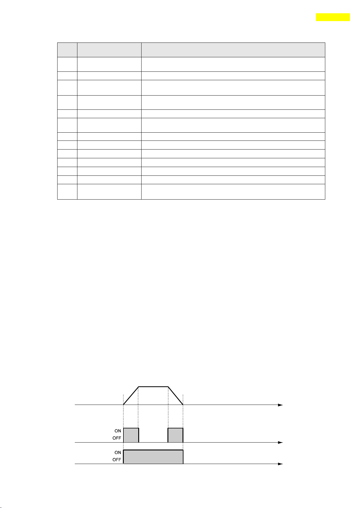
5) ‘Moving’and ‘Acc/Dec’Output
As shown below, the position starts to move by motion command, and Moving signal becomes
ON and Acc/Dec signal becomes ON in the acceleration and deceleration section only.
www.fastech.co.kr
Page 66
66
10. Control I/O Signal
* Moving signal is not related to actual position. The signal becomes to [OFF]
Just after the ‘position command’is finished.
6) ‘Org Search OK’Output
When the origin return motion is executed by origin search command, ‘Origin Search OK’
signal is set to OFF. When the origin return motion is normally finished by the origin
sensor, ‘Origin Search OK’ is set to ON. When the alarm happens, this signal is set to
OFF. Refer to 「10.3 Input Signal - 9) Origin Search Input」.
7) ‘Servo Ready’Output
When the drive supplies power to the motor by Servo ON signal or command and is ready to
perform motion command, ‘ServoReady’ signal displays ON signal. Refer to 「10.3 Input
Signal – 7) Servo On and AlarmReset Input」.
8) ‘PT(Position Table) Output 0~2 ‘Output
Control output used for ‘Start/Stop Message Function’. When these items are set, this
signal enables the user to check if corresponding PT motion starts or stops through
control output signal. If ‘Start/Stop Message Function’ is not used, this signal
should be set to 0 or 8. At the position set with other values, the motion operates as
follows.
・ If PT set items are set to ‘1~7’, when the position starts to move, PT Output HEX
value is displayed to ‘PT Output O ~ PT Output 2’.
・ If PT set items are set to ‘9~15’, the position motion is finished and then PT
Output HEX value is displayed to ‘PT Output O ~ PT Output 2’.
For more information, refer to 「 Ezi-SERVO Plus-R User Manual – Position Table
Function」.
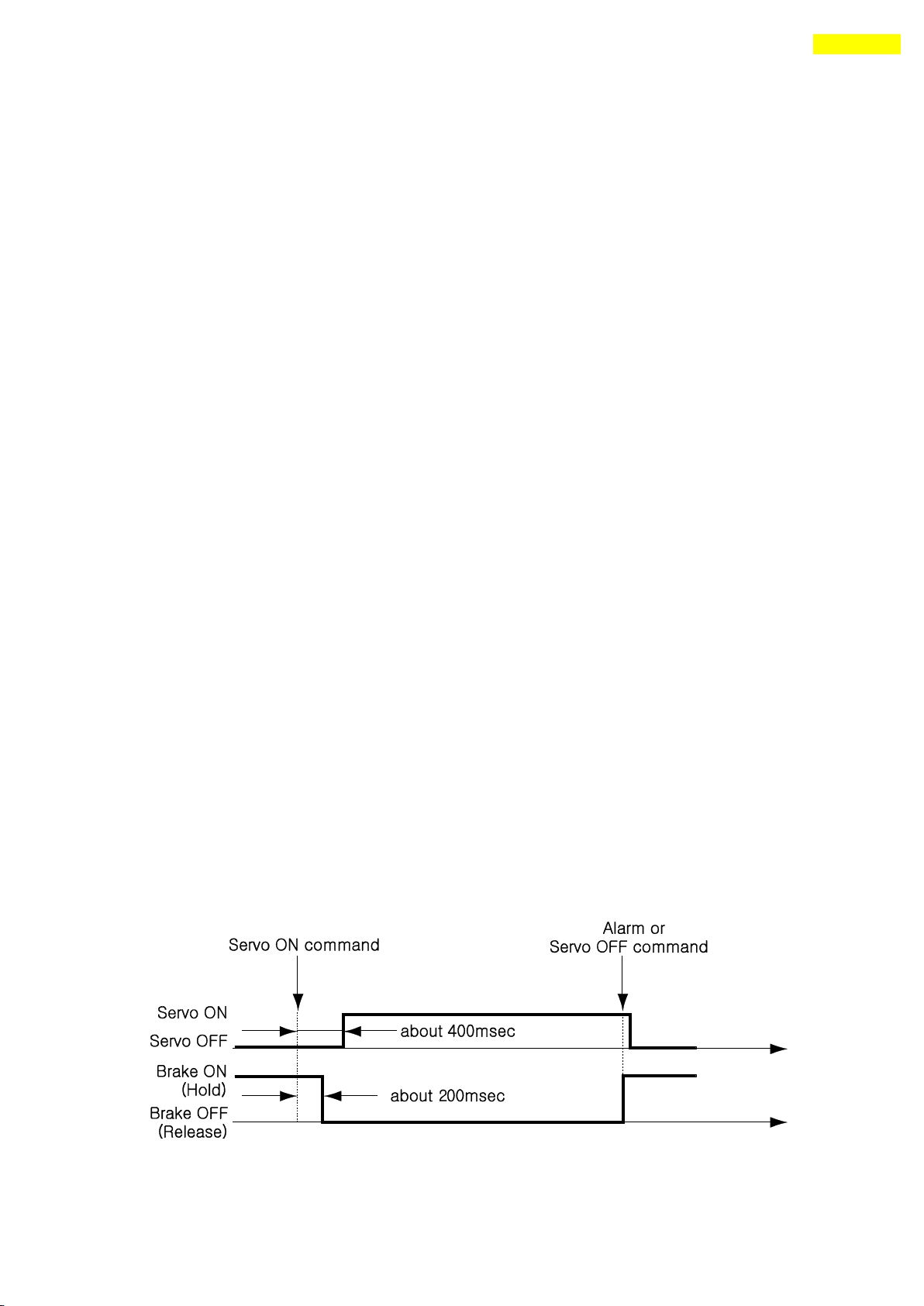
9) ‘BRAKE+’and ‘BRAKE-‘ Output
This function is used to protect motor rotation in Servo ON status by pin23
And pin24 of CN1 connector. DC +24V is connect to‘BRAKE+’for brake logic
and brake control signal is connect to ‘BRAKE-‘.
This output function must be used to the Brake that is under 200[mA]/DC24V
of current consumption.
* The delay time of ‘Brake OFF’process after Servo ON command is define in
‘Brake Delay Time [No.34]’parameter.
www.fastech.co.kr
Page 67
67
10. Control I/O Signal
10) ‘Brake’ Output for high current
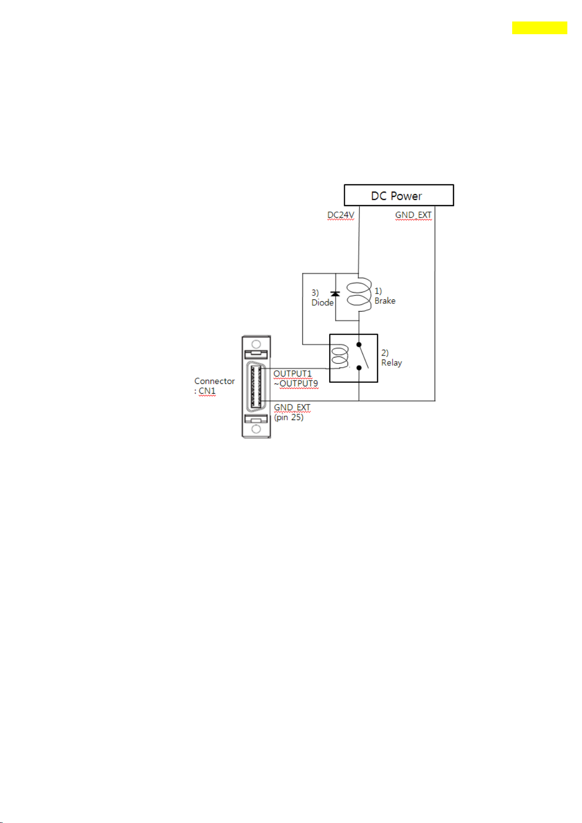
This function can be used when the Brake signal is assigned to one of OUTPUT1~
OUTPUT9 of CN1 connector. This is used for protect motor rotation in
Servo ON status. The signal timing diagram between Servo ON command and
Brake signal is same as 9) ‘BRAKE+’ and ‘BRAKE-‘ Output.
This signal used for the Brake that is over 200[mA]/DC24V of current
consumption. Brake, Relay and diode is needed for this function and the
signal connection diagram is as follows.
*1 Brake : User selected Brake
*2 Relay : under 15[mA] / DC24V
*3 Diode : 1N4004 or equivalent
www.fastech.co.kr
Page 68
68
11. Operation
If the ‘Servo ON’ signal is assigned to input pin, ServoON command
from GUI or DLL library will not executed.
Servo ON command
Position Set
Caution
11. Operation
11.1 Power Supply Timing
Ezi-SERVO Plus-R is supplied power through drive module to motor. Therefore, connect the
drive and the motor with a cable and then supply power to the drive module. After power is
supplied, the motor is basically set to Servo OFF.
11.2 Servo ON Operation
After power is supplied, set the drive module to Servo ON as follows.
① Click ‘Servo OFF’ button at the User Program(GUI).
② Give the drive a command through DLL library.
③ Assign ‘Servo ON’ to a control input pin, and supply the drive with the signal through
the pin.
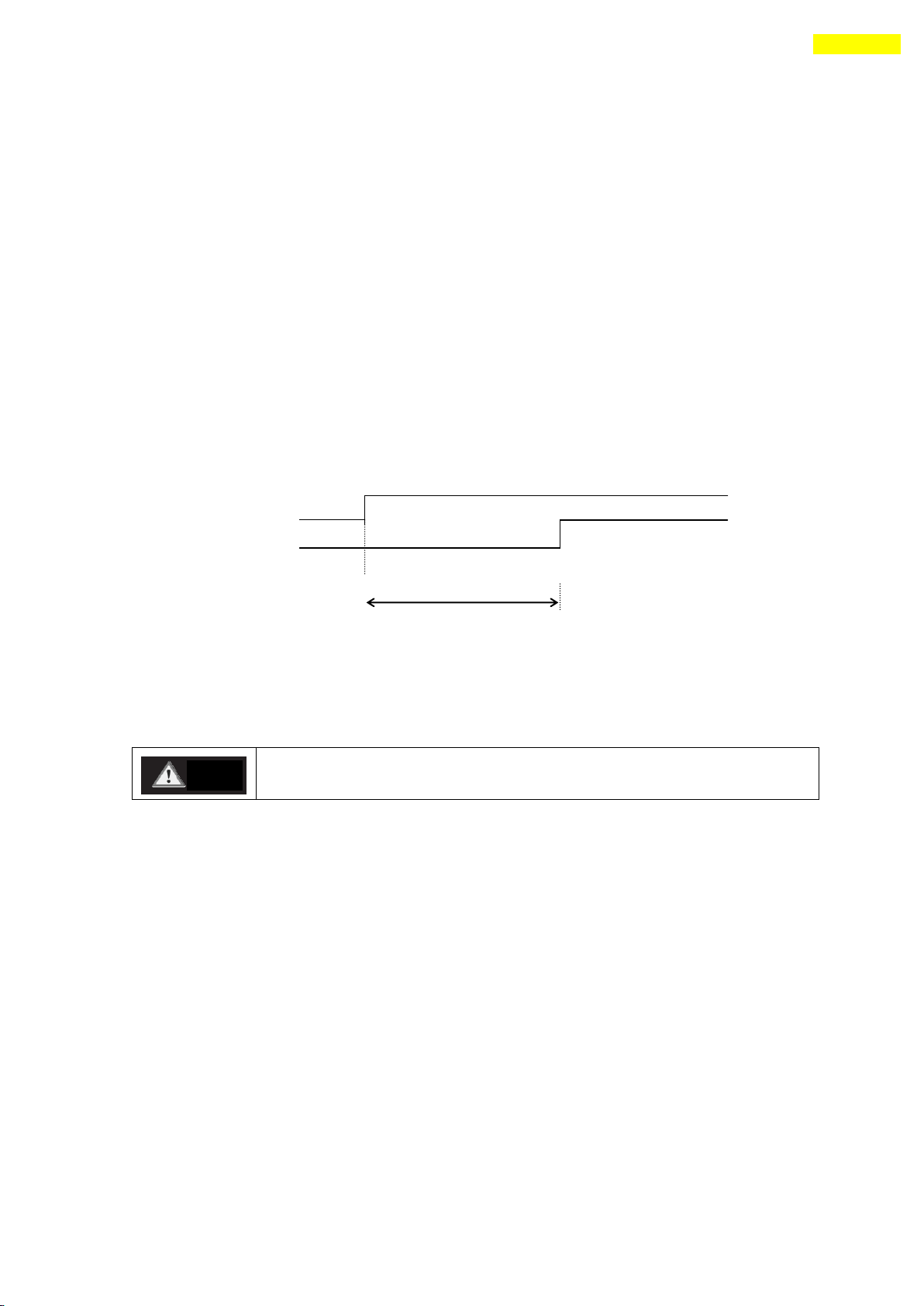
After Servo ON command is given, In-position is finished to the time as shown below.
‘t1’ is the time until Servo ON command is given and then the position is decided. It is
about 400 [msec] with factory default value and it can be change with ‘Servo ON Method
[No.33]’ parameter. It is subject to the rising time of supplying power and the motor
status.
11.3 Operation Mode
This controller can do three control operations such as I/O command, communication
command(DLL program), and User Program(GUI)
(1) I/O Command Mode
This controller can execute control operation like in-position by I/O command
transmitted from the upper controller. The in-position control operation is executed by
operating position table with I/O command.
(2) Communication Command Mode
This controller can execute control operation like in-position by command transmitted
from the upper controller. The in-position control operation is executed by operating
position table with I/O command
www.fastech.co.kr
Page 69

69
11. Operation
Parameter Name
Setting Content
Range
Axis Max Speed
Operation speed after acceleration is finished
1~2,500,000[pps]
Axis Start Speed
Operation start speed before acceleration starts
1~35,000[pps]
Axis Acc Time
Required time until the motor reaches the axis max
speed from stop status
1~9,999[ms]
Axis Dec Time
Required time until the motor reaches from the axis
max speed to the stop status
1~9,999[ms]
Motion Dir
To select motion direction (CW or CCW)
0~1
Pulse per
Revolution
Number of pulses per revolution.
The range of ‘Axis Max Speed’parameter is depend
on this value.
0~9
Position Table Operation Sequence
In case of Ezi-SERVO Plus-R, the system can execute continuous operation by position
table at the I/O command mode.
① By using PT A0 ~ PT A7 input signal or DLL program, set PT number to be operated.
② In case of Servo OFF, set the controller to Servo ON by communication program or
Servo ON control input.
③ Start to operate by rising edge of PT Start input signal or communication program.
Stopping Continuous Operation of Position Table
When the motor is executing continuous operation of position table with Ezi-SERVO Plus-R,
stop executing position table by following methods.
① To use DLL program or control input signal corresponding to ‘Stop’ and ‘E-Stop’.
In this case, operation is completely finished and is not connected to next
operation.
② The user can click 「Pause」 at User Program(GUI) to temporarily stop operating. In
this case, click 「Pause」 again, and remaining operation will be executed again.
Position Control Operation
To operate the motor by parameters set by User Program(GUI) or DLL program. (This is not
connected with PT operation.)
Once position control operation is started, PT operation command is overridden. Likewise,
while PT operation is executing, position control operation command is overridden.
The followings show parameters applied to position control operation. All position table
item values are overridden.
Teaching Function
Teaching can be executed only by User Program(GUI). For more information, refer to
「User Manual – Position Table Function」.
www.fastech.co.kr
Page 70
70
12. Other Operation Functions
PT
No.
Command
type
Position
Low
Speed
High
Speed
Accel.
time
Decel.
time
Wait
time
Continuous
Action
JP Table
No.
0 3 10000
1
2500
50
300 0 1
1 1 3
1000
1
500 - - 0 1
2
2 3 5000
1
1500
50
300
300 0 3
3 3 -2500
1
1000
300
300 0 0
-
No.
Parameter Name
Setting Value
Unit
6
Jog Speed
1500
[pps]
7
Jog Start Speed
100
[pps]
8
Jog Acc Dec Time
200
[msec]
12. Other Operation Functions
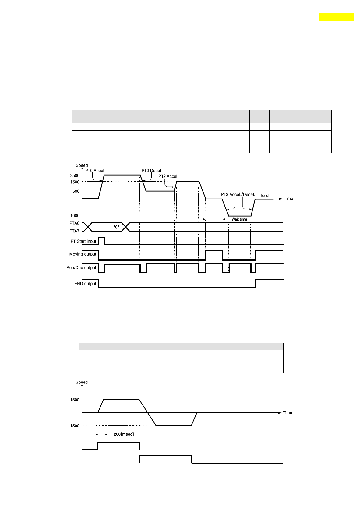
12.1 Position Table(PT) Operation Example
Input ‘PT A0~ PT A7’ signals to set PT number. Input ‘PT Start’number to execute speed
control operation. For more information, refer to 「User Manual – Position Table Function」.
【Position Table Setting】
12.2 Jog Operation Example
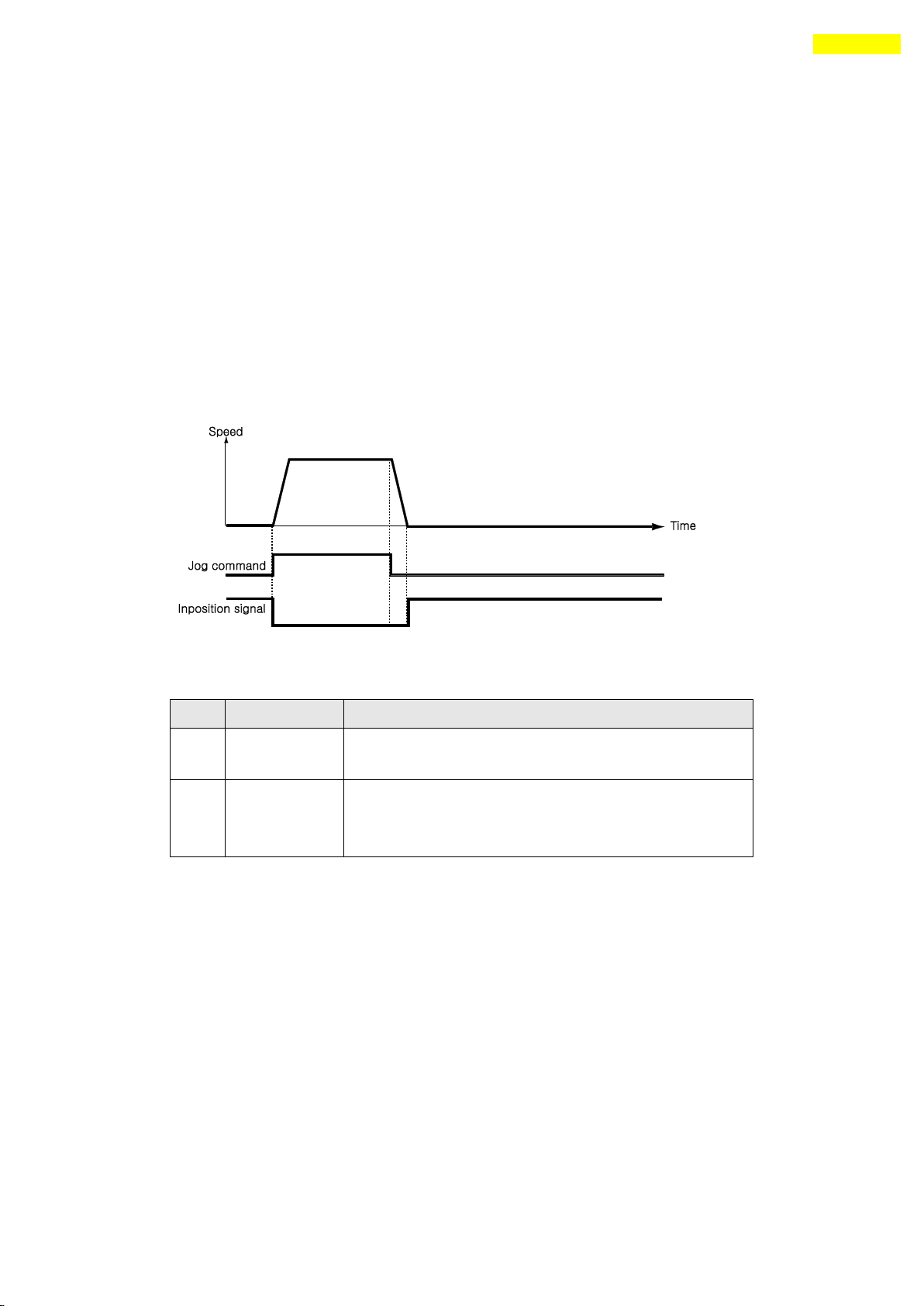
The machine executes speed control operation at the speed set by parameters according to inputting
‘Jog+’ and ‘Jog-‘ signals.
【Parameter Setting】
www.fastech.co.kr
Page 71
71
12. Other Operation Functions
Parameter Name
Description
Range
Org Speed
Operation speed when origin return starts
1~500,000[pps]
Org Search Speed
Low-speed operation speed after origin sensor is
sensed and operation start speed when origin start.
1~50,000[pps]
Org Acc Dec Time
The time assigned to the acceleration/deceleration
section when origin return starts and stops.
1~9,999[ms]
Org Method
To select how to return the origin
0~5
Org Dir
To select operation direction(CW or CCW)
0~1
Org Offset
After origin return is finished, the motor moves
additionally as this setting value and then stops.
-134,217,727 ~
134,217,727
Org Position Set
After origin return is finished, ‘Command Pos’ value
is set to this setting value.
-134,217,727 ~
134,2177,27
Org Sensor Logic
To set the origin sensor signal level.
0~1
Org Torque Ratio
To set the torque ratio during Torque origin method
10~100[%]
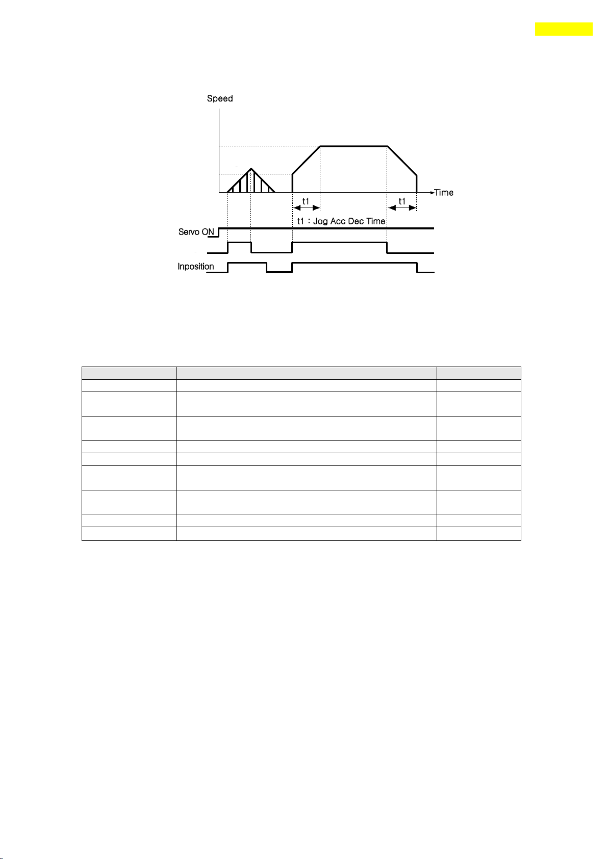
Also, when any value except 0 is set to the ‘Jog Start Speed’parameter, the relation between jog
command and in-position is shown below.
12.3 Origin Return
If the machine is operated by I/O signals, the motor can execute origin return by inputting
‘Origin Search’ signal. Also, the motor can execute origin return with User Program(GUI)
and DLL program. The following table shows parameter types related to origin return.
(1) Origin Return Method Setting
To execute origin return, ‘Org Method’ parameter should be set as follows.
www.fastech.co.kr
Page 72
72
12. Other Operation Functions
Motion speed
Origin speed
[No.17]
D2
Origin Return Command
Origin Sensor Signal
Origin Search OK Output
(when ‘Org Offset [No.22]’ is 0)
ON
OFF
D1
Motion Direction
1) D1 : Set by ‘Org Dir[No.21]’
2) D2 : Reverse of ‘D1’
Origin
Search speed
[No.18]
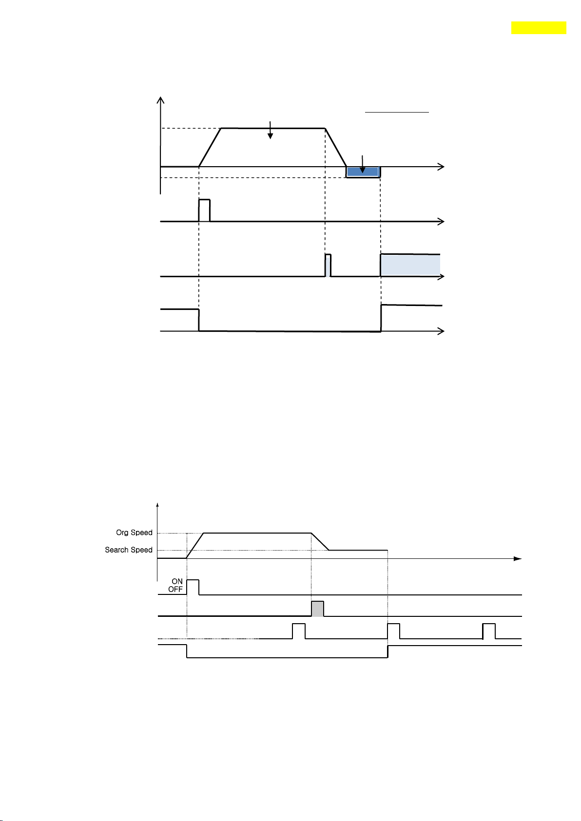
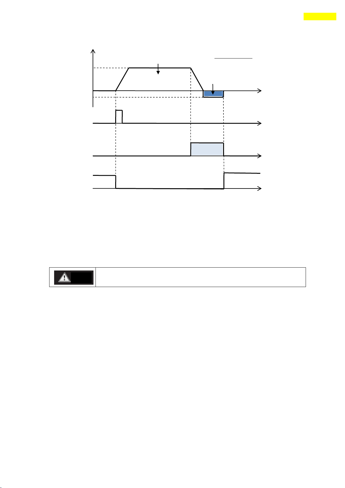
① Common Origin (In case of ‘Org Method’= 0)
The machine moves up to the origin sensor by ‘Org Speed’ and ‘Org Acc Dec Time’
parameters and then completes precise origin return at the low speed set to ‘Org
Search Speed’. When the origin sensor, the motion is stop change direction and move
upto origin sensor OFF. And finally move until origin sensor ON. If the limit sensor
is sensed while the machine is under origin return, the machine stops and reverses its
moving direction and then continues to origin return operation.
② Z-pulse Origin (In case of ‘Org Method’= 1)
The machine moves up to the origin sensor by ‘Org Speed’ and ‘Org Acc Dec Time’
parameters and then completes Z-pulse origin return at the low speed set to ‘Org
Search Speed’. That is, after the origin sensor is sensed, the machine moves slowly
to the original moving direction until Z-pulse signal is sensed.
www.fastech.co.kr
Page 73
73
12. Other Operation Functions
When the limit sensor is detected, the stop method is fixed to
‘Soft Stop’, nt depends on parameter value.
Caution
Motion speed
Origin speed
[No.17]
D2
Origin Return Command
Limit Sensor Signal
Origin Search OK Output
(when ‘Org Offset [No.22]’ is 0)
ON
OFF
D1
Motion Direction
1) D1 : Set by ‘Org Dir[No.21]’
2) D2 : Reverse of ‘D1’
Origin
Search speed
[No.18]
③ Limit Origin (In case of ‘Org Method’= 2)
The machine moves up to the position which the limit sensor is sensed by ‘Org Speed’
& ‘Org Search Speed’parameters, and stops by ‘Org Acc Dec Time’value. The moving
direction complies with as set in ‘Org Dir’.
If there’s no limit sensor on your system, you can set ‘Origin’ by ‘S/W Limit Plus
Value’ and ‘S/W Limit Minus Value’of parameters.
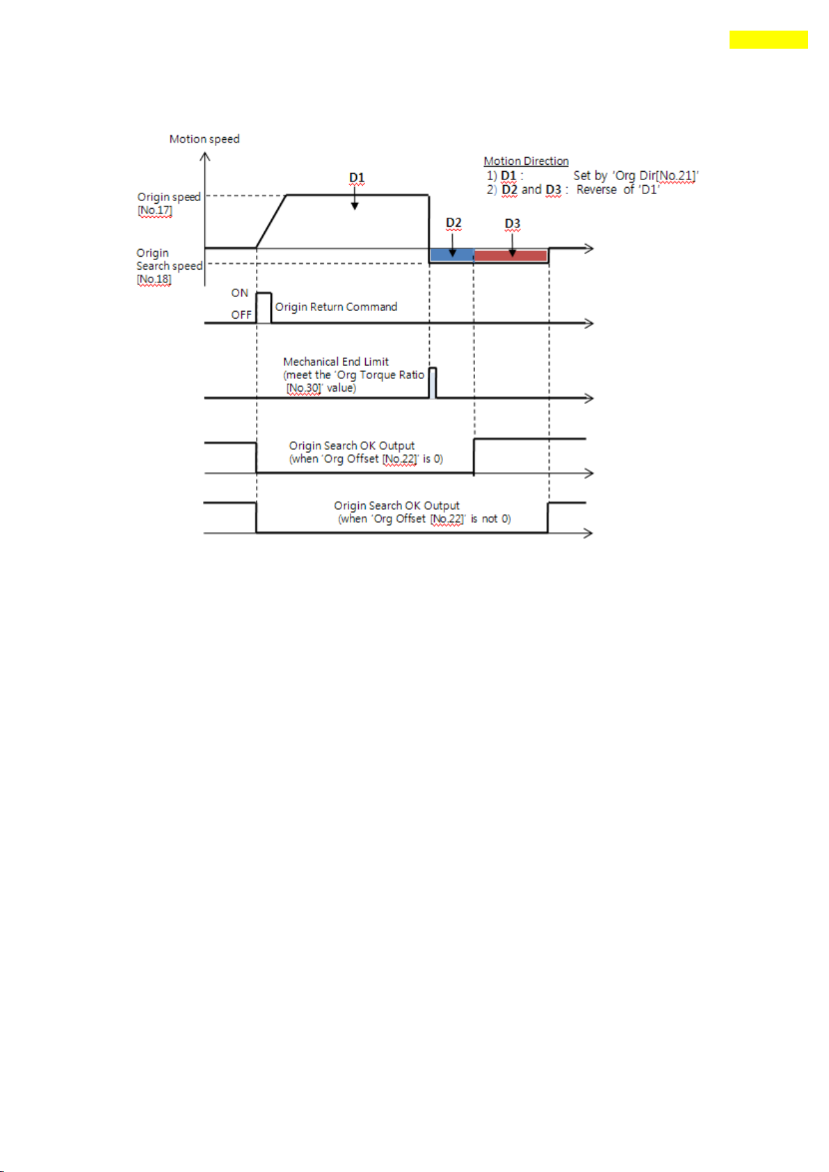
④ Torque Origin (In case of ‘Org Method’= 3 )
The machine moves up to the wall which the pushing torque is reached to ‘Org Torque
Ratio’value. This method can be used without origin sensor and without limit sensor.
If the HW limit sensor is sensed, the motion is stop and the Origin Search OK signal
Remains OFF status.
www.fastech.co.kr
Page 74
74
12. Other Operation Functions
When the machine moves up to the mechanical limit by ‘Org Dir’direction,
it stop immediately and moves in reverse direction until ‘D2’ distnace.
If the ‘Org Offset’ parameter is not 0, it moves more as ‘D3’distance.
* Be careful not to contact ‘HW limit sensor’ during torque origin command.
(By HW limit sensor, the motor will stop and command is canceled)
⑤ Torque Z Origin (In case of ‘Org Method’= 4 )
After the machine moves up to ‘Torque Origin’, it moves additionally up to
meet ‘Z-pulse’ of encoder. The motioning of‘Torque Origin’is same as
Torque Origin (In case of‘Org Method’=3) and the remaining
Z-pulse motioning is same as Z-pulse Origin(In case of ‘Org Method’=1).
* In case of this, the ‘Org Search Speed’value is working under 10000[pps].
* Be careful not to contact ‘HW limit sensor’ during torque origin command.
⑥ Set Origin (In case of ‘Org Method’=5 )
Set to origin in current mechanical position without origin sensor.
(2) Origin Return Procedure
Origin return is executed according to the following procedure.
① Set parameters required to origin return.
② If the Servo is OFF, (reset an alarm when it occurs) input a control input Servo ON
command or send a communication program so that the Servo can be ON.
www.fastech.co.kr
Page 75

75
12. Other Operation Functions
Setting Item
Description
Range
Start/Stop
Setting start/stop of pulse output.
0~1
Pulse Start
Position
Setting the start position of first
pulse output.
-134,217,727 ~
134,217,727
Pulse Period
Setting the pulse period.
( 0 : pulse output only 1 time in
Pulse start position.
1~ : pulse output repeatedly
depends on setting.)
0~134,217,727
[pulse]
Pulse Width
Setting the pulse width.
1~1000[ms]
③ Start origin return operation to the rising edge of control input origin search or
the communication program.
(3) Interruption of Origin Return
When the machine is under origin return, click ‘Stop’ or ‘E-Stop’ to stop the
machine. In this case, the machine’s origin is not edited and origin return is not
completed either.
(4) Output of Origin Return Finish
The completion of origin return operation can be decided with related bit values of
either ‘Origin Search OK’ of control output or ‘Axis Status’ of communication
program.
12.4 Stop Operation
By using two methods of control input and communication program command, the user can input
stop and emergency stop commands. Even though the emergency stop command is inputted, the
Servo will be not OFF. In case emergency stop, the machine stops immediately without
deceleration. So, a special caution for mechanical impact is required.
12.5 Trigger Pulse Output
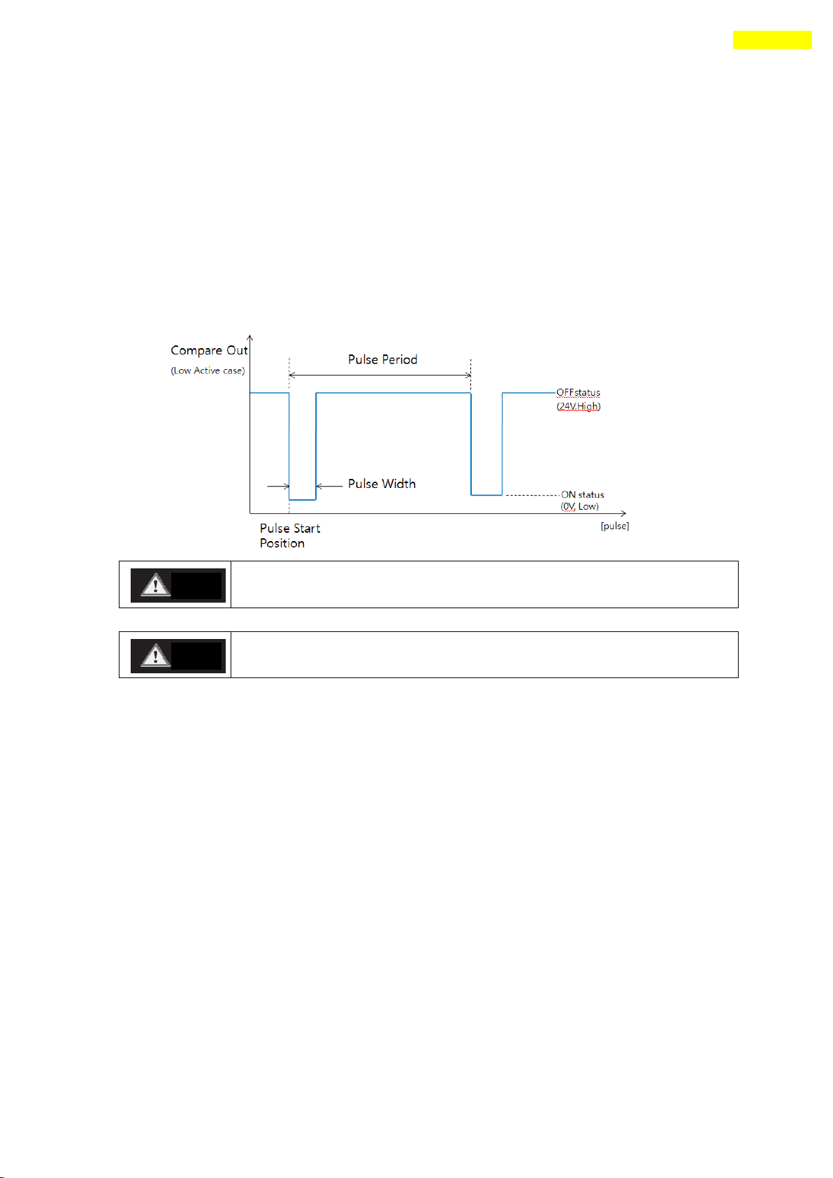
This function is used when the output signal becomes ON periodicallyin in specific
condition. This function can be used in absolute coordinate system.
(1) Setting
This function is working with RS-485 communication (DLL library) method ony.
This command can be executed during the positioning command or before the positioning
command also. The following table shows the setting conditions and refer to
「User Manual – Communication Function」.
(2) Formula for Setting Items
To calculate the minimum ‘Pulse Period’value the next formular is used.
- Motioning speed = speed[pps]
- Pulse width = pulse_width[msec]
The minimum ‘Pulse Period[pulse]’= (speed / 1000) * pulse_width * 10.
For example, the motioning speed is 100,000[pps], pulse width is 5[msec] ,
www.fastech.co.kr
Page 76
76
12. Other Operation Functions
The pulse is output only in bigger position area than ‘pulse start
position’and is output in incremental motion direction.
The sign of current position value and the sign of ‘pulse start
position’ must be same to pulse output.
Caution
Caution
The minimum ‘pulse period’ must set to more than ‘5000[pulse] value.
(3) Signal Output
This output pin of CN1 connector for Trigger Pulse is fixed to 「Compare Out」and
the signal diagram is as follows.
(4) Status Check
By using DLL program, the user can check the trigger pulse output status.
Refer to 「User Manual – Communication Function」.
www.fastech.co.kr
Page 77
77
12. Other Operation Functions
12.6 Push Motion
This function is used when the specified motor torque is needed during motioning and
Stop(only in Stop-mode) status.
This function is working only in absolute position value.
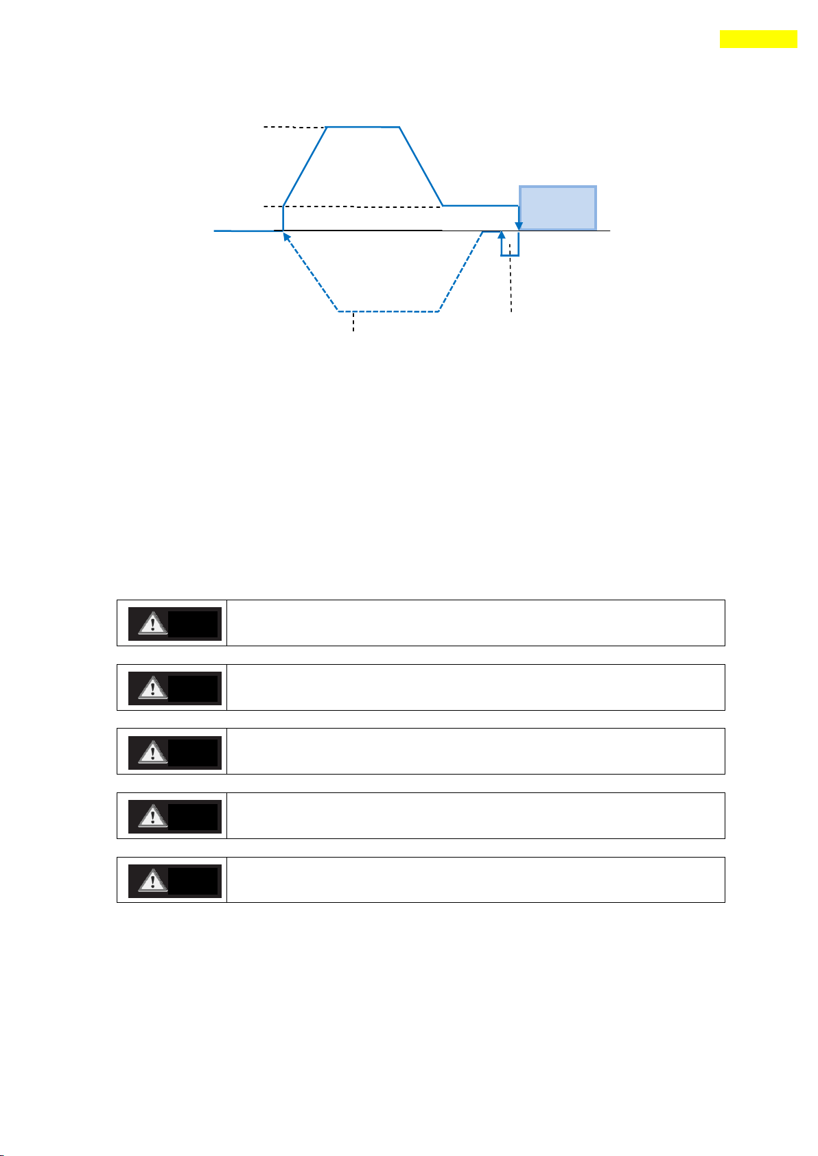
(1) Function
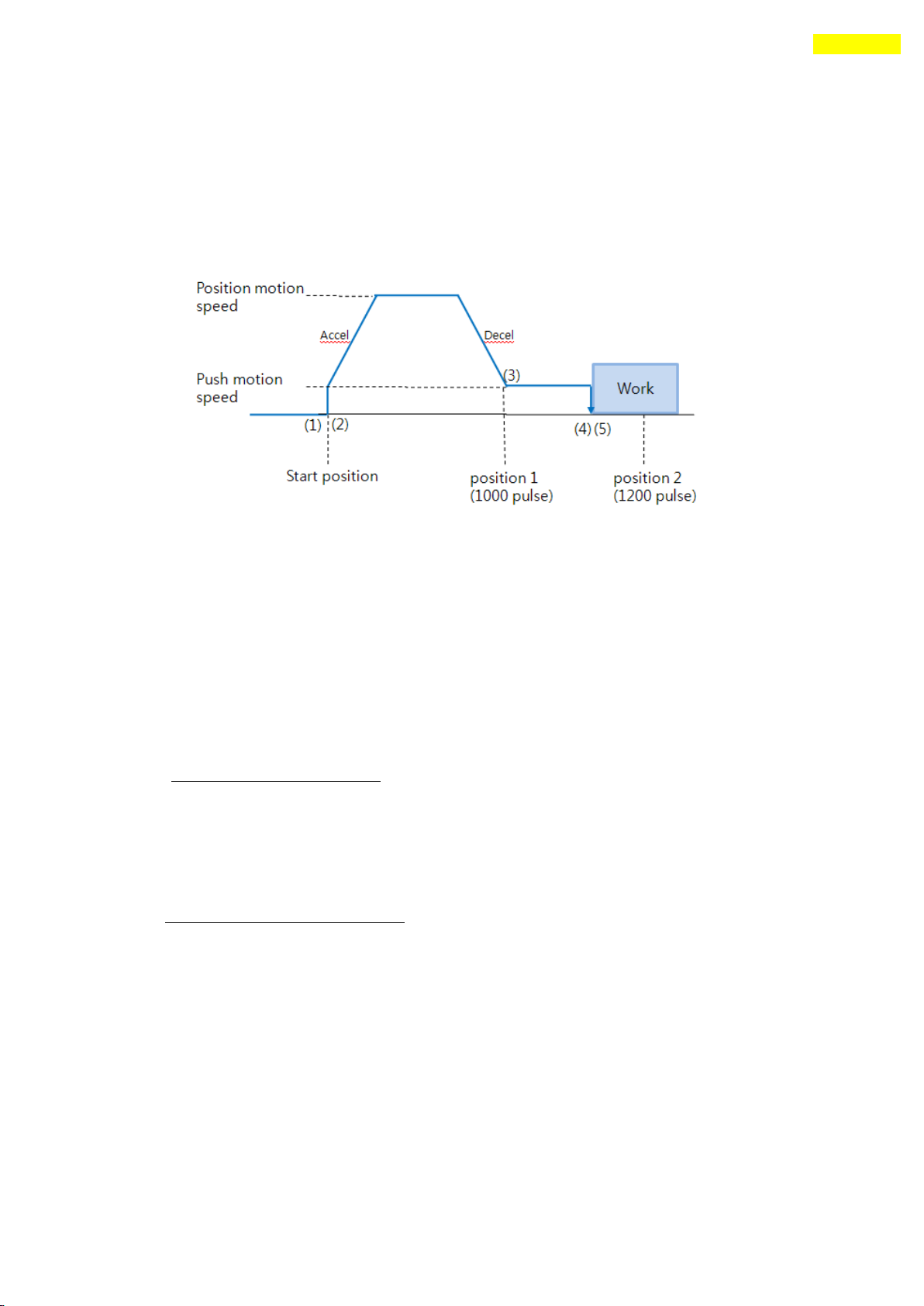
Figure 10.6.1
Start Push Motion command
Normal position motion command is executed.
(status : position mode)
Decelerate the speed from position motion to push motion.
(push motion speed must be lower than 200[rpm].)
④ Push motioning until the work detected with specified motor torque.
(status : push mode)
The motioning will stop just after the work detected.
⑤ When Push mode is ‘Stop’:
After the work detected, the motor will stop but the motor torque will be
maintained and the ‘inposition’/ ‘PT Stoped’/’END’ signal is effective.
The maintained motor torque will be return to normal(Servo ON) status by ‘stop’
command.
(status : release push mode and return to position mode)
When Push mode is ‘Non-stop’:
After the work detected, the motor will not stop and the motor torque will be
maintained and the ‘inposition’and other signal is effective.
www.fastech.co.kr
Page 78
78
12. Other Operation Functions
Non-stop mode : must be execute the ‘Stop’ command before next motion
command in the work detect situation.
If there is shock in mechanism, the time delay is needed after ‘Stop’
operation.
Extends the distance of Position motion command when Push motion is not
excuted.
If alarm happens with ‘stop’ command after push motion executed,
change the ‘Push mode’ value to bigger or smaller.
If the work can not be detect during Push Position, the push mode is
Automatically finished.
Work
Position motion
Push motion speed
Backward motion in STOP
Return motion to start
(6)
(8)
(7)
Caution
Caution
Caution
Caution
Caution
⑥ Additional the next step is needed as below diagram (Figure 10.6.2).
Figure 10.6.2
The ‘Stop’command must be executed before next motion command. (In Stop mode
it is no need to ‘stop’when there is no shock in mechanism) At this
'stop’ procedure, the motor move to backward as much as the ‘Push mode’
parameter values. This motion will be reduce the shock in mechanism. So if the Stop
command is not used, ‘Backward motion’ is also not executed. ‘Backward motion’
speed is set to 5000[pps] at this moment.
⑦ Time delay can be needed before returning to start position depends on
mechanical conditions.
⑧ Return to start position.
(2) Specification
The push torque is different for each motor size. Refer to 「4.Characteristic
of Motor Torque」.
Push ratio (from 20~90[%] ) value is referenced to stop status torque on ‘Torque
www.fastech.co.kr
Page 79
79
12. Other Operation Functions
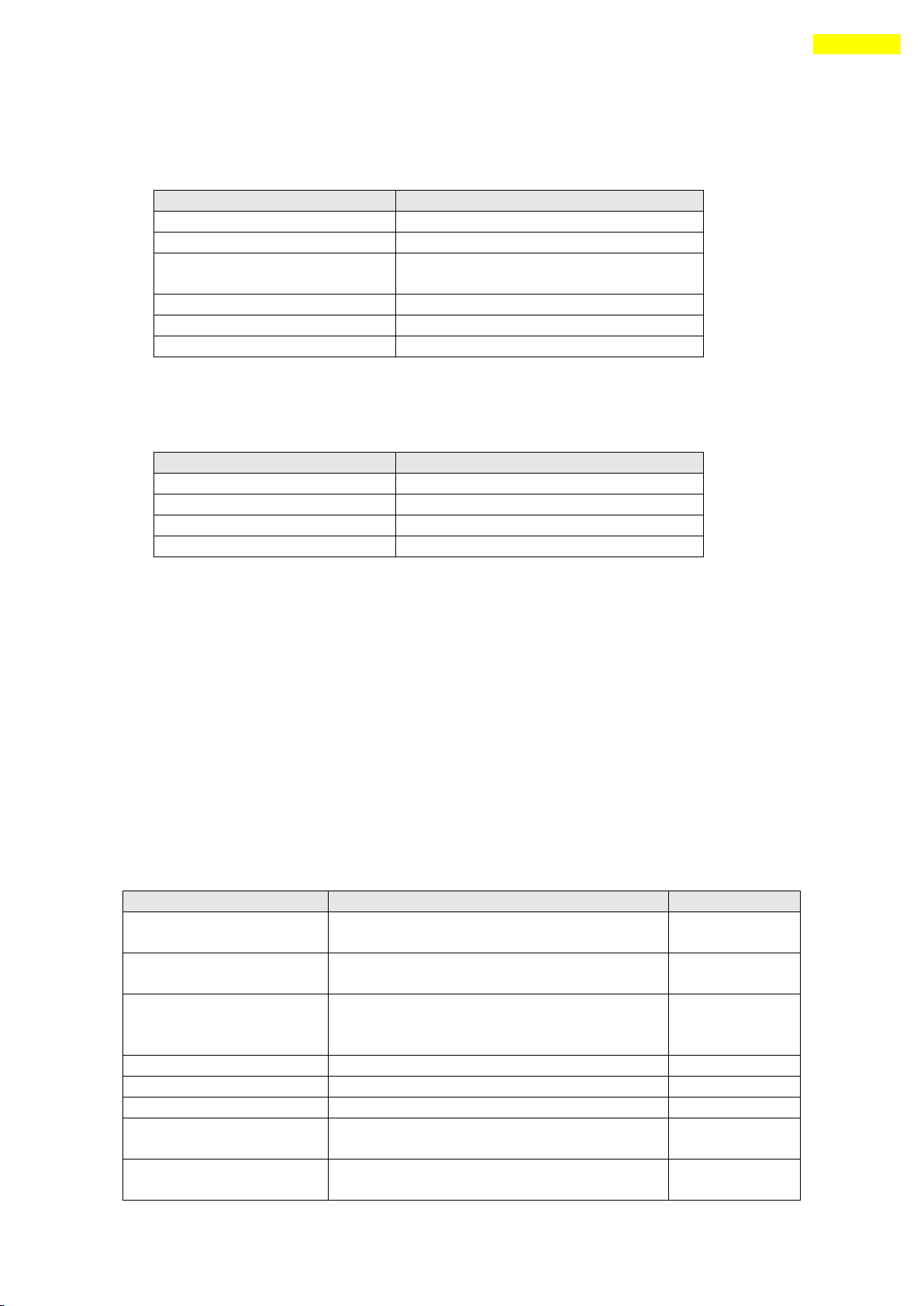
Item
MC-28VA with Ezi-SERVO-PR-MI
Pushing force [N] *1
20 ~ 83 (push ratio : 20~90 [%])
Pushing speed [mm/sec]
6.6 or less
Positioning repeatability
[mm]
0.01
Driven method
Lead screw
Max velocity [mm/s]
24
Lead [mm]
2
Item
17C2035S4 with Ezi-SERVO-PR-MI
Pushing force [N] *1
22 ~ 106 (push ratio : 20~90 [%])
Pushing speed [mm/sec]
19.05 or less
Driven method
Lead screw
Lead [mm]
6.35
Setting Item
Description
Range *1
Position command Start
speed
Start speed value of position motion
1~35000[pps]
Position command Moving
speed
Moving speed of position motion
1~500000[pps]
Position command Target
position
Absolute taregt position value of
position command
(‘position 1’ of Figure10.6.1)
134,217,727 ~
134,217,727
Accel time
Accel time of position motion
1~9,999[ms]
Deceleration time
Decelerate time of position motion
1~9,999[ms]
Push ratio
Motor torque value in push mode
20~90[%]
Push command Moving
speed
Moving speed of Push motion
(max 400[rpm])
1~66000[pps]
Push command Target
position
Absolute taregt position value of
push command
134,217,727 ~
134,217,727
Graph’. And the accuracy is -10 ~ +10[%].
When this function is working specially in Ezi-Actuator that is combined
Ezi-SERVO-PR-MI and MC-28VA cylinder, the push motion characteristic is as follows.
*1 : Accuracy is -10 ~ +10 [%]
When this function is working specially in Captive LinearStep that is combined
Ezi-SERVO-PR-MI and 17C2035S4 motor, the push motion characteristic is as follows.
*1 : Accuracy is -10 ~ +10 [%]
(3) Setting Method
This function is working only in absolute position value. The position error can
happen due to the work status in push mode. Push motion command can be executed
by 2 methods. One is RS-485 communication(DLL library) method and the other is
external digital signal(PT Start command) method.
DLL library method
The following table shows the setting conditions and refer to 「User Manual
– Communication Function」.
There is another library for status checking of push motioning.
www.fastech.co.kr
Page 80
80
12. Other Operation Functions
(‘position 2’ of Figure10.6.1)
*Non-stop mode : the value must be set
more than ‘ Position command Target
Position’ value.
*The motor will stop if the position is
exceed this value even if the work is not
detected.
Push mode
Set Stop mode(0) or Non-stop mode(1~
10000) after the work detect. In case of
Non-stop mode, the motor move backward as
much as this value[pulse] distances.
0~10,000
*1 : The unit of [pps] in this item is referenced to 10,000[ppr] encoder.
Input signal(PT Start) Method
Firstly the position table data must be entered before the push motioning and
refer to 「User Manual – Position Table Function」.
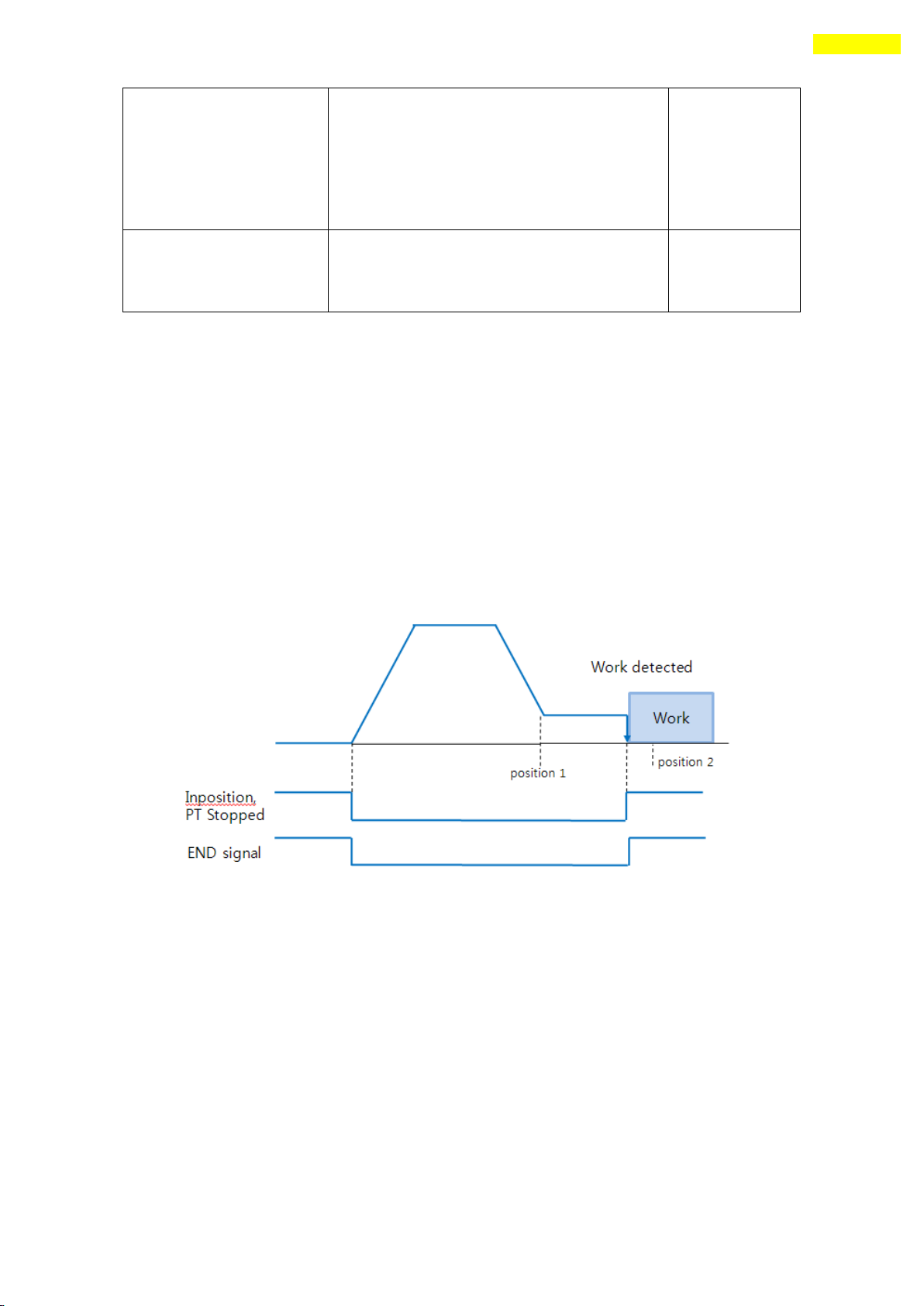
(4) Status Check
Basically the current push motion status can be checked by DLL library and
Additionally can be checked by Flag(Inposition & PT Stoped signal) and Output
(END signal) as follows.
Work detected
Work not detected
The ‘Inposition’ and other signals are still OFF when the work is not detected.
By ‘stop’ command these signals change to ON status. If the work is overdue
after work detect(‘Inposition’ signal is ON), the ‘Inposition’ signal change to OFF
status. But the ‘PT Stopped/END’signal is still ON after the first work detect.
The push command is stoped at ‘position 2’(absolute position value in push command).
(5) Alarm
Basically the alarm (#3 and #4) function is not working during push motion moving.
This is because of the position error and overload alarm can be happen in push mode.
If the alarm happens during return to start position after finishing push motioning,
increase the parameter ’27. Position Tracking Limit’value.
www.fastech.co.kr
Page 81
81
13. Communication Function
If Windows goes to the stand-by mode, serial communication is
basically disconnected. So, after recovering from the stand-by mode,
the user should connect communication again. This content is equally
applied to the library provided with the product.
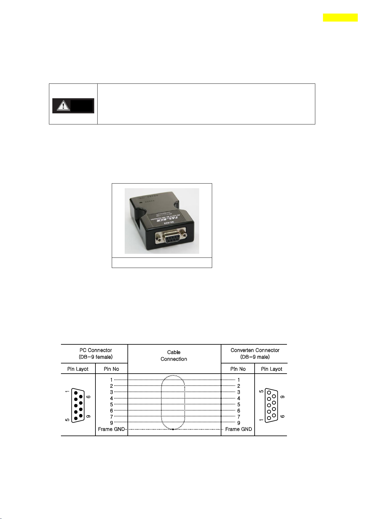
RS-485 Converter (to RS-232)
Caution
13. Communication Function
In case of RS-485, up to 16 axes can be controlled by the multi-drop link(daisy chain).
13.1 Connection with the PC
There are one method of connecting between the drive and the PC by RS-485(serial
communication). PC’s RS-232C port can be used. By using following communication converters
according to each communication type, the user can connect the PC and the drive module. The
maximum communication speed is 115200[bps] with RS-232 to RS-485 converter.
For connection with the PC, refer to 「5.2 Controller Configuration」.
1) Cable of Connecting RS232 Port (to PC) and Converter (RS232 ↔ RS-485)
Normally Power does not need to be supplied to the converter module. But when
the communication have problems without power, DC 5~24V external power can be connected.
The signal is wired as follows.
www.fastech.co.kr
Page 82
82
13. Communication Function
RJ45 Pin No.
UTP CAT5E cable
Function
1
White/Orange
GND
2
Orange
GND
3
White/Green
Data+
4
Blue
GND
5
White/Blue
GND 6 Green
Data-
7
White/Brown
GND 8 Brown
GND
case
Frame GND
Signal cable ‘Data+’ and ‘Data-’ are differential type signals.
These two signal cables must be twisted.
The cable length of RS-485 Converter<->Drive or Drive<->Drive must be
longer than 60 cm.
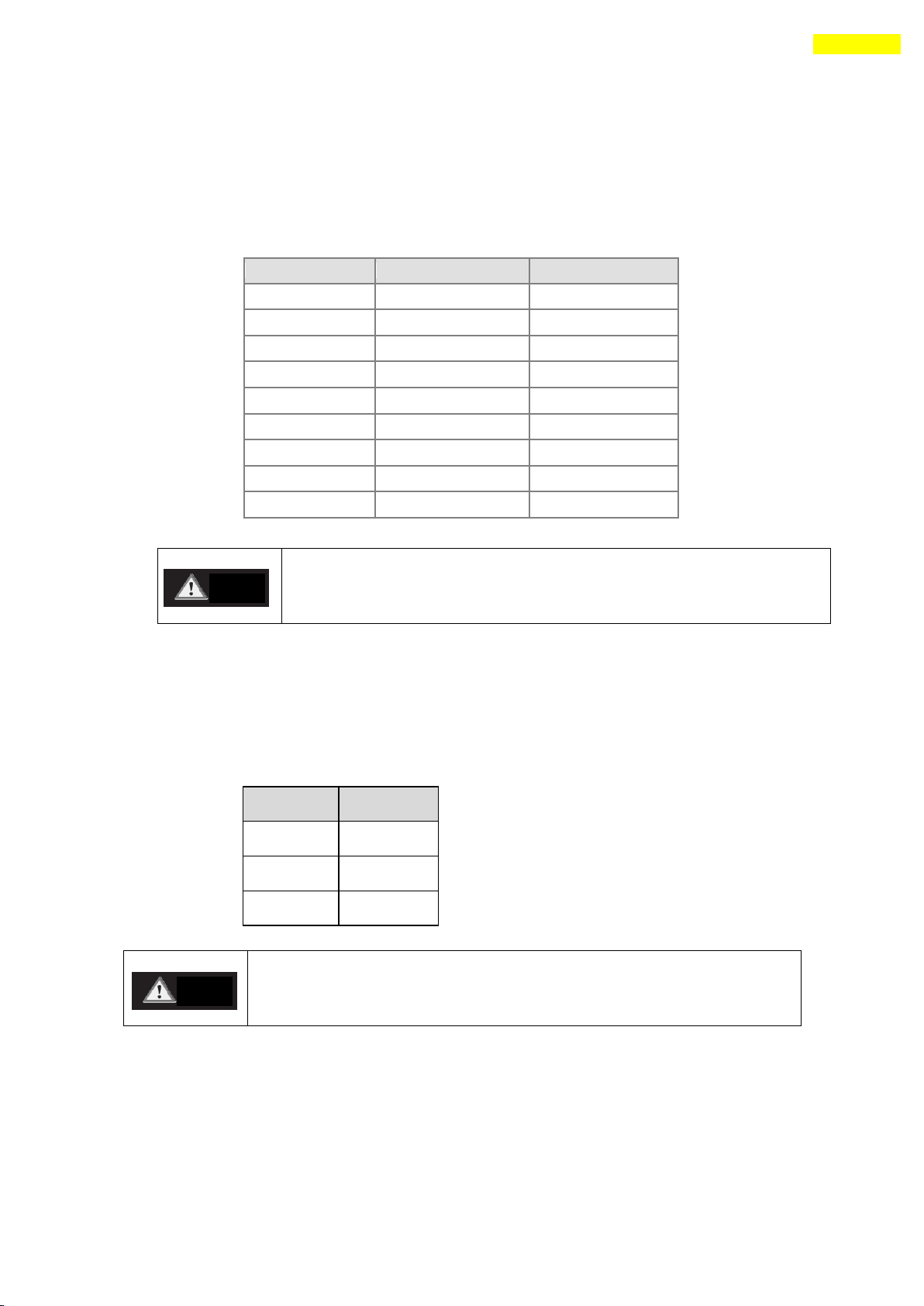
Pin No.
Function
1
Data+
2
Data-
3
GND
Caution
Caution
2) Cable of connecting RS-485 Converter and Drive Module(CN5 : Ezi-SERVO-PR only)
Connector Type : RJ45
Cable Type : LAN cable, CAT5E or better (UTP or STP)
Signal Wiring : Standard Straight Wiring
(1↔1, 2↔2, 3↔3,…, 8↔8)
If multi-axis connection is required at one segment, up to 16 drive modules can be
connected by the daisy-chain method. The pin signal content is as follows.
3) Cable of connecting RS-485 Converter and Drive Module(CN5) : Ezi-SERVO-PR-MI and
Ezi-SERVO-ALL
Signal Wiring : Standard Straight Wiring
(1↔1, 2↔2, 3↔3)
If multi-axis connection is required at one segment, up to 16 drive modules can be
connected by the daisy-chain method. The pin signal content is as follows.
www.fastech.co.kr
Page 83
83
13. Communication Function
13.2 Communication Interface Circuit
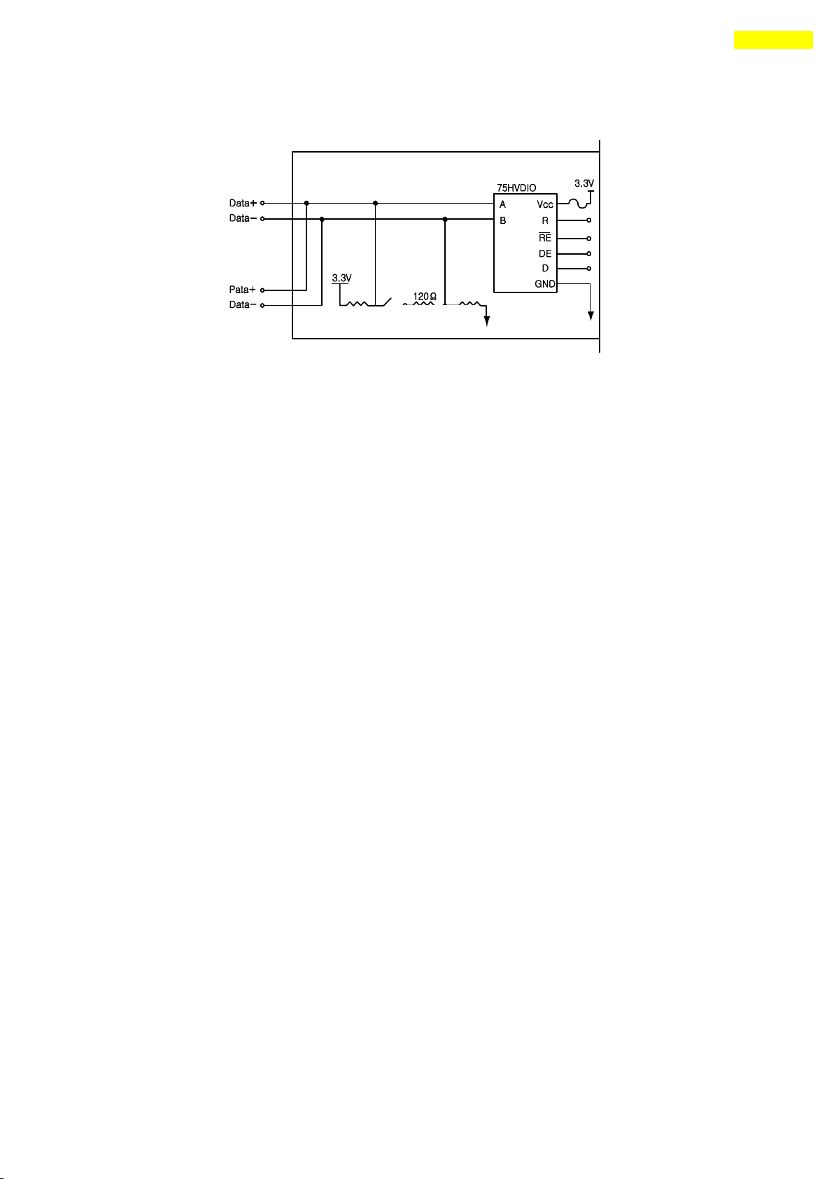
The above figure shows an I/O circuit of RS-485 communication interface signal. When
communication is connected, Ezi-SERVO Plus-R maintains to receive stand-by status. It
performs sending only when it receives the signal from upper communication and then replies.
For more information about communication function, refer to 「 User Manual – Communication
Function」 in a separate volume.
www.fastech.co.kr
Page 84

84
14. Protective Function
Flash
Count
Alarm Name
Description
1
Overcurrent
The current through power devices in inverter exceeds the limit
value *1
2
Overspeed
Command speed for motor exceeds 3300[rpm].
3
Position Tracking
Position error value is higher than specified value*1 in
position command status . *2
4
Overload
The motor is continuously operated more than 5 second under a
load exceeding the max. torque.
5
Overheat
The internal temperature of the drive exceeds 85℃.
6
Over regeneratived
voltage
Back-EMF more than limit value. *3
7
Motor connection
The connection of drive and motor is defective.
8
Encoder connection
The connection of drive and encoder is defective.
9
Motor voltage error
The power supplied to the motor is less than low limit value.*4
10
Inposition error
After operation is finished, a position error occurs.
11
System error
Drive system is halted(Watch Dog Timer).
12
ROM error
Read/Write error on ROM device in drive system.
15
Pos. Error Overflow
Position error value is higher than specified value*1 in motor
stop status. *6
14. Protective Function
14.1 Alarm Type
When an alarm occurs while the controller is operating, a red LED among status display LEDs
flash and the following protective function will be displayed according to the number of LED
flash counting.
Alarm Table
*1 4.5A : EzS-NDR-20, EzS-NDR-28, EzS-NDR-42, EzS-NDR-56, EzS-NDR-60 model
9.0A : EzS-NDR-86 model
*2 Values[pulse] of parameter ‘Pos Tracking Limit[No.27]
*3 70V : EzS-NDR-20, EzS-NDR-28, EzS-NDR-42, EzS-NDR-56, EzS-NDR-60 model
90V : EzS-NDR-86 model
*4 20V : EzS-NDR-20, EzS-NDR-28, EzS-NDR-42, EzS-NDR-56, EzS-NDR-60 model
40V : EzS-NDR-86 model
*6 Values[pulse] of parameter ‘Pos. Error Overflow Limit[No.33]
14.2 Acquiring Alarm Information
When an alarm occurs, the motor become Servo OFF and then stops by free run and at the same
time displays alarm message.
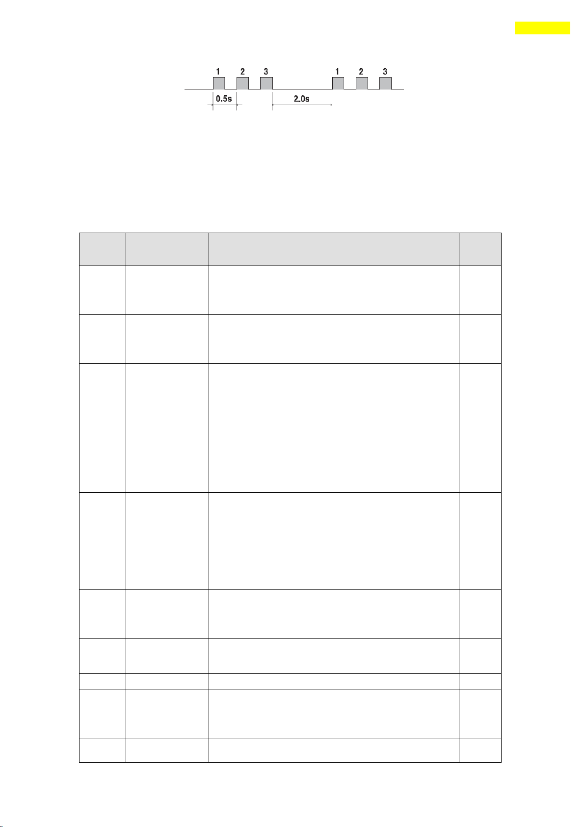
Also, ‘AlarmBlink’ signal repeats On/Off according to the timing as illustrated below. The
red LED flash every 0.5 second in accordance with alarm number and wait for 2 seconds. And
then red LED flash repeatedly until inputting ‘AlarmReset’signal.
(Example) Alarm 3: ‘AlarmBlink’display signal occurred when the step-out is occured.
www.fastech.co.kr
Page 85
85
14. Protective Function
Flash
Count
Alarm Name
Description
Reset
1
Overcurrent
1)Check the motor’s short-circuit (A, /A, B, /B)
2)Check the mechanical status such as parameter
setting.
Valid
2
Overspeed
1)Check parameter setting, and abnormal operation of
the motor.
2)Check the speed command of upper controller(ex:PLC).
Valid
3
Position
Tracking
1)Get down the load or increase the acceleration or
deceleration speed.
2)Check assemble status of mechanism.
3)Check the brake signal cable.
4)Check the motor’s short-circuit (A, /A, B, /B)
5)Check the encoder cable connection status.
6)Check the parameter(27:Position Tracking Limit)
setting value.
Valid
4
Overload
1)Compare the motor’s rating with load scale.
2)Check assemble status of mechanism.
3)Check ‘SW limit’value of parameter.
4)Check the status of sensors.
5)Check the motorDB for driver and motor.
6) Check the motor’s short-circuit (A, /A, B, /B)
Valid
5
Overheat
1)Get down the ambient temperature or install a
cooling fan.
2)Check the distance is over 50mm between drivers.
Valid
6
Over
regeneratived
voltage
1)In case of high-speed operation, check if the
acceleration or deceleration speed is low.
Valid
7
Motor connection
1)Check the connection status of drive and motor.
Invalid
8
Encoder
connection
1)Check the connection status of drive and encoder.
2)Check the screw condition, cabling short-circuit of
encoder.
Invalid
9
Motor voltage
error
1)Check if power is supplied to the drive.
Invalid
14.3 Alarm Check and Release
If an alarm occurs, remove its cause and then release it. The alarm can be released as
follows. In case of alarms of which ‘Reset’column is indicated to ‘Invalid’, power must
get down prior to releasing the alarms.
www.fastech.co.kr
Page 86
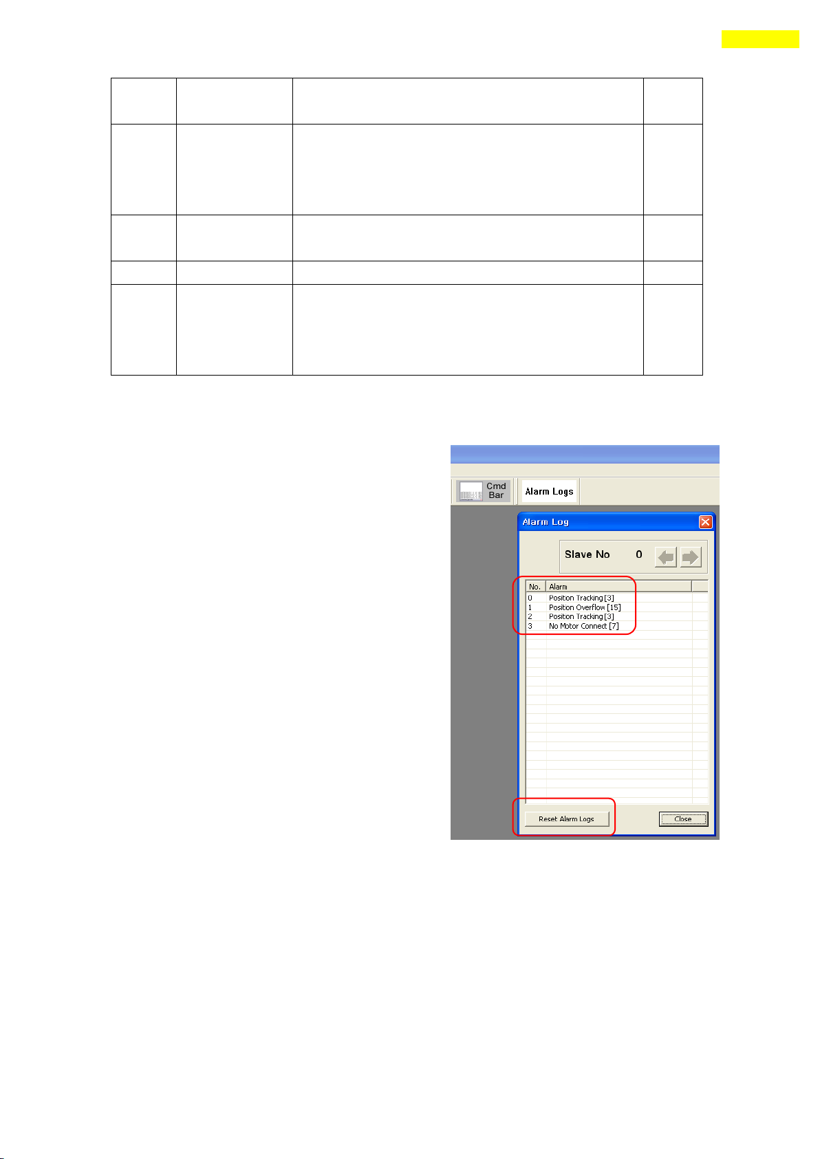
86
14. Protective Function
2)Check the diameter and length of power cable to
driver.
10
Inposition error
1)Check if parameters are set correctly or the machine
is over-loaded.
2)Check the vibration of mechanism and belt tension.
3)Check the cabling status of motor and encoder.
Valid
11
System error
1)Check if current of power supply is supplied to the
drive.
Invalid
12
ROM error
1)Contact to distributor.
Invalid
15
Pos. Error
Overflow
1)Get down the load or increase the acceleration or
deceleration speed.
2)Check the brake and encoder is working correctly or
not.
Valid
14.4 Alarm Log
If an alarm occurs, its log informations are save in
ROM area in the drive.
The maximum number of alarm logs are 30.
The inquiry of alarm log is possible only on
Servo OFF status.
To remove alarm log, use the ‘Reset Alarm
Logs’ menu.
www.fastech.co.kr
Page 87

87
15. Parameter
No
Name
Unit
Lower Limit
Upper Limit
Default
0
Pulse per Revolution
0 9
9
1
Axis Max Speed
[pps]
1
2,500,000
500,000
2
Axis Start Speed
[pps]
1
35,000
1
3
Axis Acc Time
[msec]
1
9,999
100
4
Axis Dec Time
[msec]
1
9,999
100
5
Speed Override
[%] 1 500
100
6
Jog Speed
[pps]
1
2,500,000
5,000
7
Jog Start Speed
[pps]
1
35,000
1
8
Jog Acc Dec Time
[msec]
1
9,999
100
9
Servo Alarm Logic
0 1
0
10
Servo On Logic
0 1
0
11
Servo Alarm Reset Logic
0 1
0
12
S/W Limit Plus Value
[pulse]
-134,217,727
+134,217,727
+134,217,727
13
S/W Limit Minus Value
[pulse]
-134,217,727
+134,217,727
-134,217,727
14
S/W Limit Stop Method
0 1
1
15
H/W Limit Stop Method
0 1
1
16
Limit Sensor Logic
0 1
0
17
Org Speed
[pps]
1
500,000
5,000
18
Org Search Speed
[pps]
1
500,000
1,000
19
Org Acc Dec Time
[msec]
1
9,999
50
20
Org Method
0 4
0
21
Org Dir 0 1 0
22
Org Offset
[pulse]
-134,217,727
+134,217,727
0
23
Org Position Set
[pulse]
-134,217,727
+134,217,727
0
24
Org Sensor Logic
0 1
0
25
Position Loop Gain
0 15
4
26
Inpos Value
0 15
0
27
Pos Tracking Limit
[pulse]
0
+134,217,727
5,000
28
Motion Dir
0 1
0
29
Limit Sensor Dir
0 1
1
30
Org Torque Ratio
[%]
20
90
50
31
Pos. Error Overflow Limit *2
[pulse]
0
+134,217,727
5,000
32
Pos. Value Counting Method
[pulse] 0 1
0
33
Servo ON Method *3
0 1
1
34
Brake Delay Time *3
[msec]
10
5000
400
35
Reserved
36
Run Current *4
*10 [%] 5 15
10
37
Stop Current *4
*10 [%] 2 10
5
38
Boost Current *4
*50 [%] 0 7
0
15. Parameter
15.1 Parameter List
*1 It can be applied over the Firmware version of 08.13.045.1
*2 It can be applied over the Firmware version of 06.03.043.10
www.fastech.co.kr
Page 88

88
15. Parameter
*3 It can be applied over the Firmware version of 06.0x.063.51
*4 It can be applied over the Firmware version of 06.0x.063.61
15.2 Encoder Setup
The setup of encoder can do in‘No.0 (Pulse per Revolution)’ item on next table.
Normally the resolution of encoder is 10000. If the resolution is 20000, 32000 or
other value, you have to set ‘0’in parameter setup.
If you don’t use default value for ‘No.0 (Pulse per Revolution)’, ‘Position Error’
can happen because of the function of Electronic Gear Ratio.
www.fastech.co.kr
Page 89

89
15. Parameter
No.
Description
Unit
Lower
Limit
Upper
Limit
Default
0
Pulse per Revolution :
Number of pulses per revolution.
If this value is changed, the motor is set to Servo OFF.
*1 : In case of encoder resolution is 2000,4000, 16000, 20000
32000
Value
Pulse/Revolution
Value
Pulse/Revolution
0
500 *1
5
3600 1 500 6 5000 2 1000 7 6400 3 1600 8 7200 4 2000
9
10000
0 9 9
1
Axis Max Speed :
When position moving commands(absolute move, incremental move) are
given, this mode sets the maximum speed which the motor can
operate. So, the motor cannot be operated faster than this value
in any case. This value is set to [pps] unit.
Upper Limit value has limit by encoder resolution value.
*in case of 10,000 : 500,000
In case of 32,000 : 1,600,000
pps
1
2,500,000
500,000
2
Axis Start Speed :
When position moving commands(absolute move, incremental move) are
given, this mode sets the operation start speed to [pps] unit.
pps 1 35,000
1
3
Axis Acc Time :
When position moving commands(absolute move, incremental move) are
given, this mode sets the acceleration section of operation start
segment to [msec] unit.
Possible range is different from Axis Speed.
(Ex.1) Axis Start Speed=1, Move Speed=400000 : 1~14316 [msec]
(Ex.2) Axis Start Speed=1, Move Speed=10000 : 1~356 [msec]
msec 1 9,999
100
4
Axis Dec Time :
When position moving commands(absolute move, incremental move) are
given, this mode sets the deceleration section of operation stop
segment to [msec] unit.
Possible range is different from Axis Speed same as ‘Axis Acc
Time’parameter
msec 1 9,999
100
5
Speed Override :
When position moving commands(absolute move, incremental move) are
given, the operation speed is subject to the ratio set to ‘Move
Speed’.
(Ex) If current move speed is 10,000 and speed override is 200,
actual motion speed is set to 20,000.
% 1 500
100
6
Jog Speed :
When jog position moving command is given, this mode sets the
motor revolution value to [pps] unit.
pps
1
2,500,000
5000
7
Jog Start Speed :
When jog position moving command is given, this mode sets the
operation start speed to [pps] unit.
pps 1 35,000
1
8
Jog Acc Dec Time :
In case of jog operation, this mode sets the time of acceleration
and deceleration sections to [msec] unit.
Possible range is different from Axis Speed.
(Ex.1) Axis Start Speed=1, Move Speed=400000 : 1~14316 [msec]
(Ex.2) Axis Start Speed=1, Move Speed=10000 : 1~356 [msec]
msec 1 9,999
100
15.3 Parameter Description
www.fastech.co.kr
Page 90

90
15. Parameter
9
Servo Alarm Logic :
When the motor or the drive is defective and so alarm signal
output is ON through CN1 connector, this mode sets the output
signal level.
♦ 0 : 0 V (Active low level)
♦ 1 : 24V (Active high level)
0 1
0
10
Servo On Logic :
By using the input pin of CN1 connector, the drive may be
converted into Servo ON. In this case, this mode sets the input
signal condition so that the drive can be Servo ON.
♦ 0 : When 0 V (low level) is inputted, servo is set to ON.
♦ 1 : When 24V(high level) is inputted, servo is set to ON.
0 1 0
11
Servo Alarm Reset Logic :
When the motor or the drive is detected to generate alarm, this
mode sets the input signal level to release the alarm signal.
Before releasing the alarm signal, the user must release its
cause.
♦ 0 : 0 V (Active low level)
♦ 1 : 24V(Active high level)
0 1 0
12
S/W Limit Plus Value :
When position moving commands(absolute move, incremental move,
jog) are given, this move set the maximum input limit that the
motor can move to the plus(+) direction with 28 bits.
When position reach to this value during ‘Limit Origin’, it will
be recognized to the Origin.
When this value set to ‘0’, S/W Limit function is canceled
pulse
-134,217,
727
+134,217,
727
+134,217,
727
13
S/W Limit Minus Value :
When position moving commands(absolute move, incremental move,
jog) are given, this move set the minimum input limit that the
motor can move to the minus(-) direction with 28 bits.
When position reach to this value during ‘Limit Origin’, it will
Be recognized to Origin.
When this value set to ‘0’, S/W Limit function is canceled
pulse
-134,217,
727
+134,217,
727
-134,217,
727
14
S/W Limit Stop Method :
Sets how to stop the motor by SW Limit Plus/Minus Value’, not
stop motion by the limit sensor.
♦ 0 : stops the motor immediately by emergency stop mode.
♦ 1 : stops the motor gradually by soft stop mode.
0 1
1
15
H/W Limit Stop Method:
In case of stop motion by the limit sensor, this mode sets how to
stop the motor.
♦ 0 : stops the motor immediately by emergency stop mode.
♦ 1 : stops the motor gradually by soft stop mode.
0 1
1
16
Limit Sensor Logic :
Sets the signal level so that the motor can recognize limit
sensor’s input to ON.
♦ 0 : 0 V (Active low level)
♦ 1 : 24V(Active high level)
0 1
0
www.fastech.co.kr
Page 91

91
15. Parameter
17
Org Speed :
In case of origin return command, this modes sets the operation
speed until the motor senses the origin sensor to [pps] unit.
pps 1 500,000
5,000
18
Org Search Speed :
In case of origin return command, The low operation speed for
precise origin return after the motor senses the origin sensor is
set to [pps] unit by this mode.
pps 1 500,000
1,000
19
Org Acc Dec Time :
In case of origin return command, the acceleration/deceleration
section time of the operation start/stop segment is set to [msec]
unit by this mode.
msec 1 9,999
50
20
Org Method :
The user can select origin return command types.
♦ 0 : The motor moves up to the origin sensor spot by ‘Org
Speed’ and then executes precise origin return at the low
value of ‘Org Search Speed’.
♦ 1 : The motor moves up to the origin sensor spot by ‘Org
Speed’ and then executes Z-pulse origin return at the low
value of ‘Org Search Speed’.
♦ 2 : The motor moves up to the limit sensor spot by ‘Org
Speed’ and then immediately stops.
♦ 3 : The motor moves up to the wall by ‘Org Torque Ratio’ and
then immediately stops.
♦ 4 : The motor moves up to the wall by ‘Org Torque Ratio’ and
then executes Z-pulse origin return at the low value of ‘Org
Search Speed’.
♦ 5 : To set origin in current mechanical position..
For more information, refer to ‘12.3 Origin Return’.
0 5
0
21
Org Dir :
In case of origin return, this mode sets the revolution direction
of the motor.
♦ 0 : moves the motor clockwise.
♦ 1 : moves the motor counterclockwise.
0 1
0
22
Org Offset :
After origin return is completed, the motor moves additionally as
this setting value and then stops. ‘Command Pos/Actual Pos’is
set to ‘0’.
pulse
-134,217,
727
+134,217,
727
0
23
Org Position Set :
After origin return is completed, ‘Command Pos/Actual Pos’value
is set to this setting value.
pulse
-134,217,
727
+134,217,
727
0
24
Org Sensor Logic :
Sets the origin sensor signal level so that the motor can
recognize origin sensor’s input to ON.
♦ 0 : 0 V (low level)
♦ 1 : 24V(high level)
0 1
0
25
Position Loop Gain :
After the motor stops, this mode controls the motor’s response by
a load attached to the motor. The user can control this value by
the motor’s load and so get the motor’s performance that
responds fast and stably. Set this mode as follows.
1) Set the value to ‘0’.
2) Increase the value until the motor’s response is stabilized.
3) Previously adjust the setting status by increasing/decreasing
one or two steps of the current setting value.
0 15
4
www.fastech.co.kr
Page 92
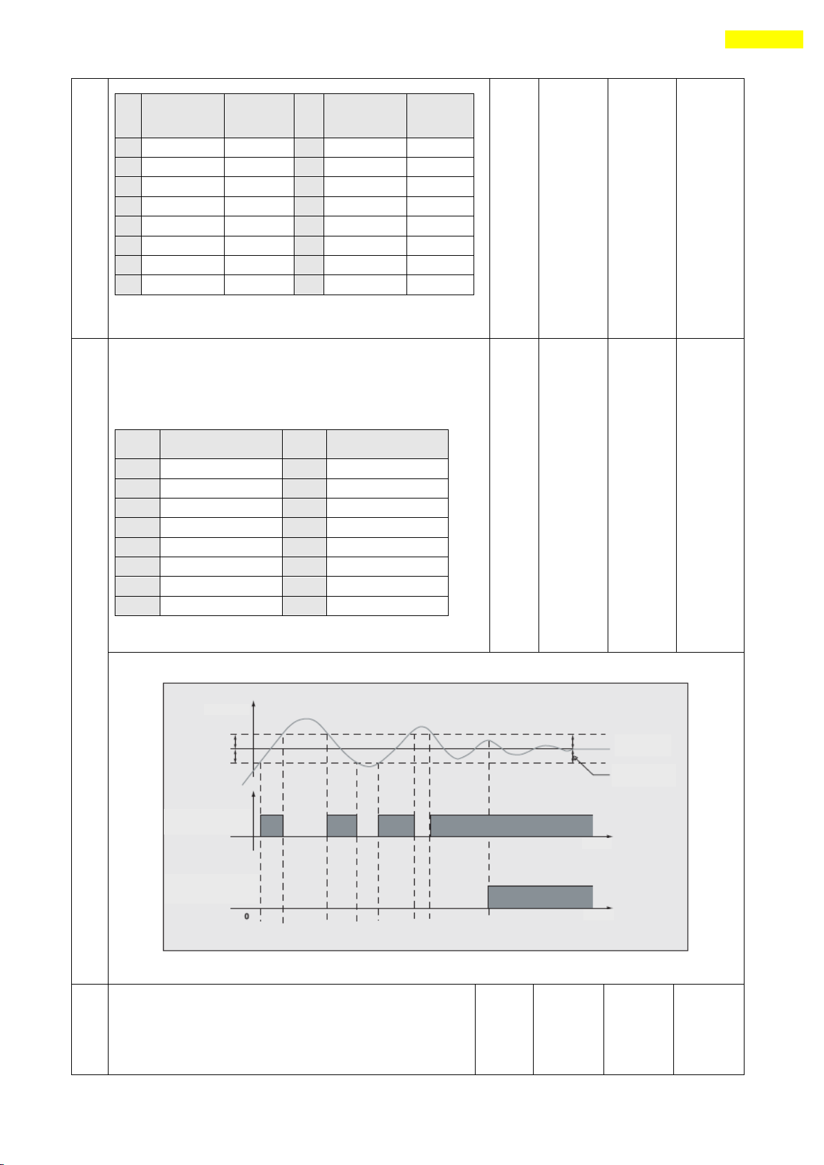
92
15. Parameter
Va
lu
e
Integral
Part’s Time
Constant*
Proportion
al Gain*
Va
lu
e
Integral
Part’s Time
Constant*
Proportio
nal Gain*
0 1 1 8 2
3 1 1
2 9 2
4
2 1 3
10 2 5
3 1 4
11 3 1 4 1
5
12 3 2
5 1 6
13 3 3
6 2 1
14 3 4 7 2
2
15 3 5
* The above value is not the actual value used inside the drive
but the relative value.
26
Inpos Value :
Sets the output condition of the in-position finish signal. After
position command pulse is finished, when the position deviation
from target position is within ‘Inpos Value’, this mode displays
in-position finish signal.
Value
In-position [pulse]
Fast Response
Value
In-position [pulse]
Accurate Response
0 0 8
0
1 1 9 1 2 2 10
2
3 3 11
3
4 4 12 4 5 5 13
5
6 6 14
6
7 7 15
7
0 15
0
Fast response and accurate response can be controlled as illustrated below.
27
Pos Tracking Limit :
Acts to protect the motor and the drive. While the motor is
run, when ‘Position Error’ is greater than this setting
value, this mode generates an alarm to stop a flow of
electricity to the motor and then set it to Servo OFF.
pulse
1
+134,217,
727
5,000
www.fastech.co.kr
Page 93

93
15. Parameter
28
Motion Dir :
When the motor operates by position command, this mode sets the
revolution direction of the motor.
♦ 0 : moves the motor clockwise.
♦ 1 : moves the motor counterclockwise.
If this parameter is changed, normally ‘Limit Sensor Dir’is
also changed.
0 1
0
29
Limit Sensor Dir :
Sets the limit sensor direction to stop the motor to the limit
spot under operation.
♦ 0 : When operation direction is ‘CW’, input the sensor
signal to the Limit+ direction, and the motor will stop.
♦ 1 : When operation direction is ‘CW’, input the sensor
signal to the Limit- direction, and the motor will stop.
If this parameter is changed, normally ‘Motion Sensor Dir’is
also changed.
0 1
0
30
Org Torque Ratio :
This parameter can be used only when ‘Origin Method’ is
‘3’. To set the maximum torque value to stop the motor with
some material(wall)
%
20
90
50
31
Pos. Error Overflow Limit :
Acts to protect the motor and the drive. While the motor stops
and is set to Servo ON, when ‘Position Error’ is greater than
this setting value, this mode generates an alarm to stop a flow
of electricity to the motor and then set it to Servo OFF. *2
pulse
1
+134,217,
727
5,000
32
Pos. Value Counting Method :
To select the display type of ‘position’ value.
♦ 0 : When the position value is display in positive and
negative value together.
♦ 1 : When the position value is display only in positive
value. This type can be used in one direction
motioning.
0 1
0
33
Servo ON Method :
To select the Servo ON processing depends on mechanical
characteristics.
♦ 1 : When the normal process is enough and it takes about
400[msec].
♦ 0 : For the safe Servo ON process on big friction mechanism
and it takes about 2~3 [sec]. *3
0 1
1
34
Brake Delay Time :
To set the delay time of brake control signal depends on
Servo ON process. *3
msec
10
5000
400
35
Run Current :
To set the maximum value of the current of motor during
operates by position command. *4
*10[%] 5 15
10
36
Stop Current :
To set the maximum value of the current of motor while the
motor stop. *4
*10[%] 2 10
5
37
Boost Current :
To set the maximum value of the current of motor during
accelerate or decelerate operation. *4
*50[%] 0 7
0
*1 It can be applied over the Firmware version of 08.13.045.1
*2 It can be applied over the Firmware version of 06.03.043.10
*3 It can be applied over the Firmware version of 06.0x.063.51
*4 It can be applied over the Firmware version of 06.0x.063.61
www.fastech.co.kr
Page 94
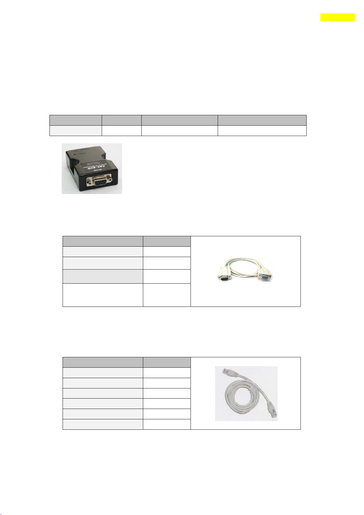
94
Appendix
Type
Item
Max comm. Speed [bps]
External Power
RS485 to RS232
FAS-RCR
115,200
No need (5~24VDC optional)
Item
Length
CGNR-C-1R8F
1.8m
CGNR-C-003F
3m
CGNR-C-005F
5m
Item
Length
CGNR-R-0R6F
60cm
CGNR-R-001F
100cm
CGNR-R-1R5F
150cm
CGNR-R-002F
200cm
CGNR-R-003F
300cm
CGNR-R-005F
500cm
Appendix
Option for RS-485 Communication
■ RS485 Converter : Common
Available to communicate between the PC and the drive. One module per multi-drop
link is required.
FAS-RCR
■ RS232 Connection Cable for FAS-RCR : Common
Universal DB-9 male-female type cable is used.
For more information wiring diagram and connector, refer to 「13. Communication Function」.
■ RS-485 Connection Cable : Ezi-SERVO-PR only
Universal RJ-45 (STP:CAT5E category) straight type cable is used.
For more information wiring diagram and connector, refer to 「13. Communication Function」.
For cabling position, refer to ⑤ of 「5.2 Controller Configuration」.
www.fastech.co.kr
Page 95
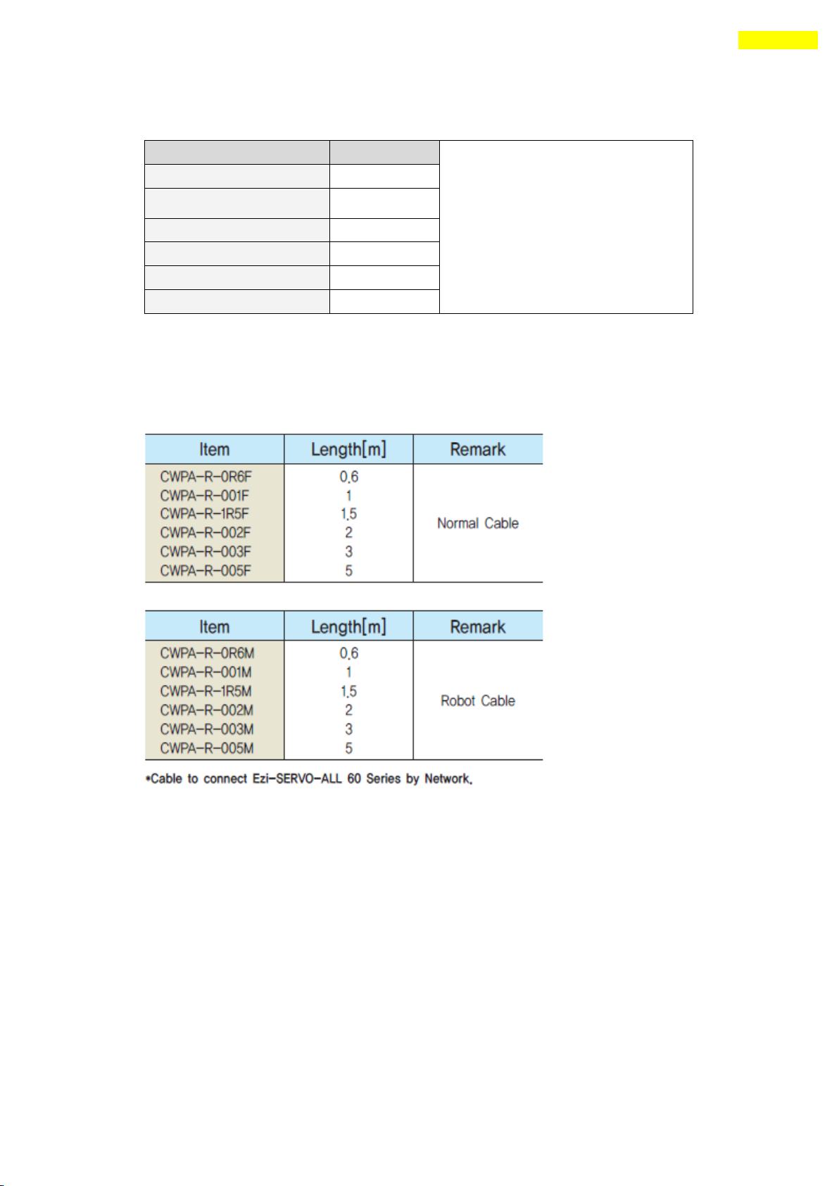
95
Appendix
Item
Length
CGNA-R-0R5F
50cm
CGNA-R-001F
100cm
CGNA-R-1R5F
150cm
CGNA-R-002F
200cm
CGNA-R-003F
300cm
CGNA-R-005F
500cm
■ RS-485 Connection Cable : Ezi-SERVO-PR-MI / Ezi-SERVO-ALL42 / Ezi-SERVO-ALL56
For more information wiring diagram and connector, refer to 「13. Communication Function」.
■ RS-485 Connection Cable : Ezi-SERVO-ALL60
For more information wiring diagram and connector, refer to 「13. Communication Function」.
www.fastech.co.kr
Page 96
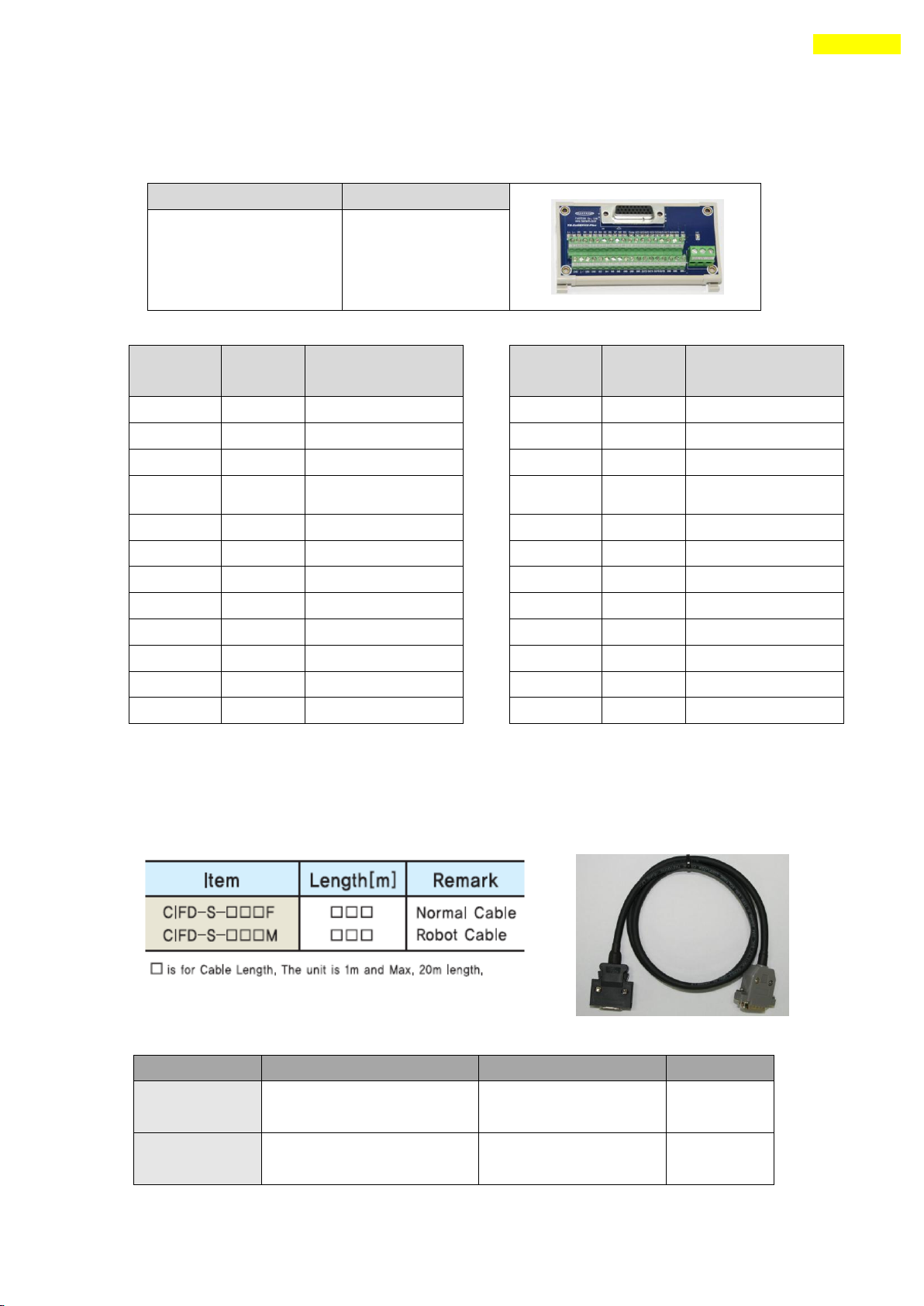
96
Appendix
Use
Item
Specification
Maker
Terminal Block
connector
Connector
DB-26 male type
Drive
connector(CN1)
Connector Housing
Backshell
10126-30000VE
10320-52AO-008
3M
3M
Type
Item
Interface (Terminal
Block) Board
TB-Plus
No. of
CN1
Signal
name
Signal name of
TB-Plus
1
Limit+
L+
2
Limit-
L-
3
Origin
ORI
4
IN1
I1
5
IN6
I6
6
IN7
I7
14
IN2
I2
15
IN3
I3
16
IN4
I4
17
IN5
I5
18
IN8
I8
19
IN9
I9
No. of
CN1
Signal
name
Signal name of
TB- Plus
7
COMP
CO
8
OUT1
O1
9
OUT2
O2
10
OUT3
O3
11
OUT4
O4
12
OUT5
O5
13
OUT6
O6
20
OUT7
O7
21
OUT8
O8
22
OUT9
O9
23
Brake+
B+
24
Brake-
B-
Option for Interface Board : Ezi-SERVO-PR only
■ Terminal Block
■ Extension cable for Interface Board
Available to extend the distance between the terminal block board and the drive.
The cable connection is 1:1 straight type.
www.fastech.co.kr
Page 97
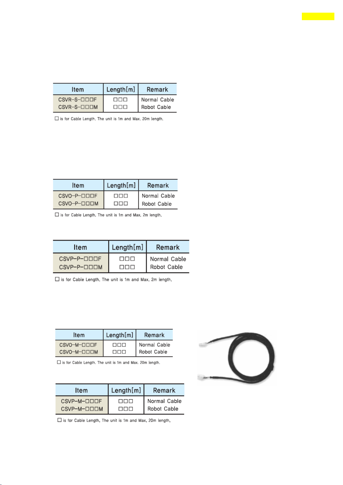
97
Appendix
Option for Motor Drive : Ezi-SERVO-PR only
■ Cable for Input/Output Signal
Available to connect between Control System and Ezi-SERVO Plus-R.
Refer to ① of 「5.2 Controller Configuration」.
■ Cable for Power
Available to connect between Power and Ezi-SERVO Plus-R.
Next is for 86mm drive.
Refer to ④ of 「5.2 Controller Configuration」.
■ Extension Cable for Motor
Available to extended connection between motor and Ezi-SERVO Plus-R.
Next is for 86mm drive.
Refer to ③ of 「5.2 Controller Configuration」.
www.fastech.co.kr
Page 98
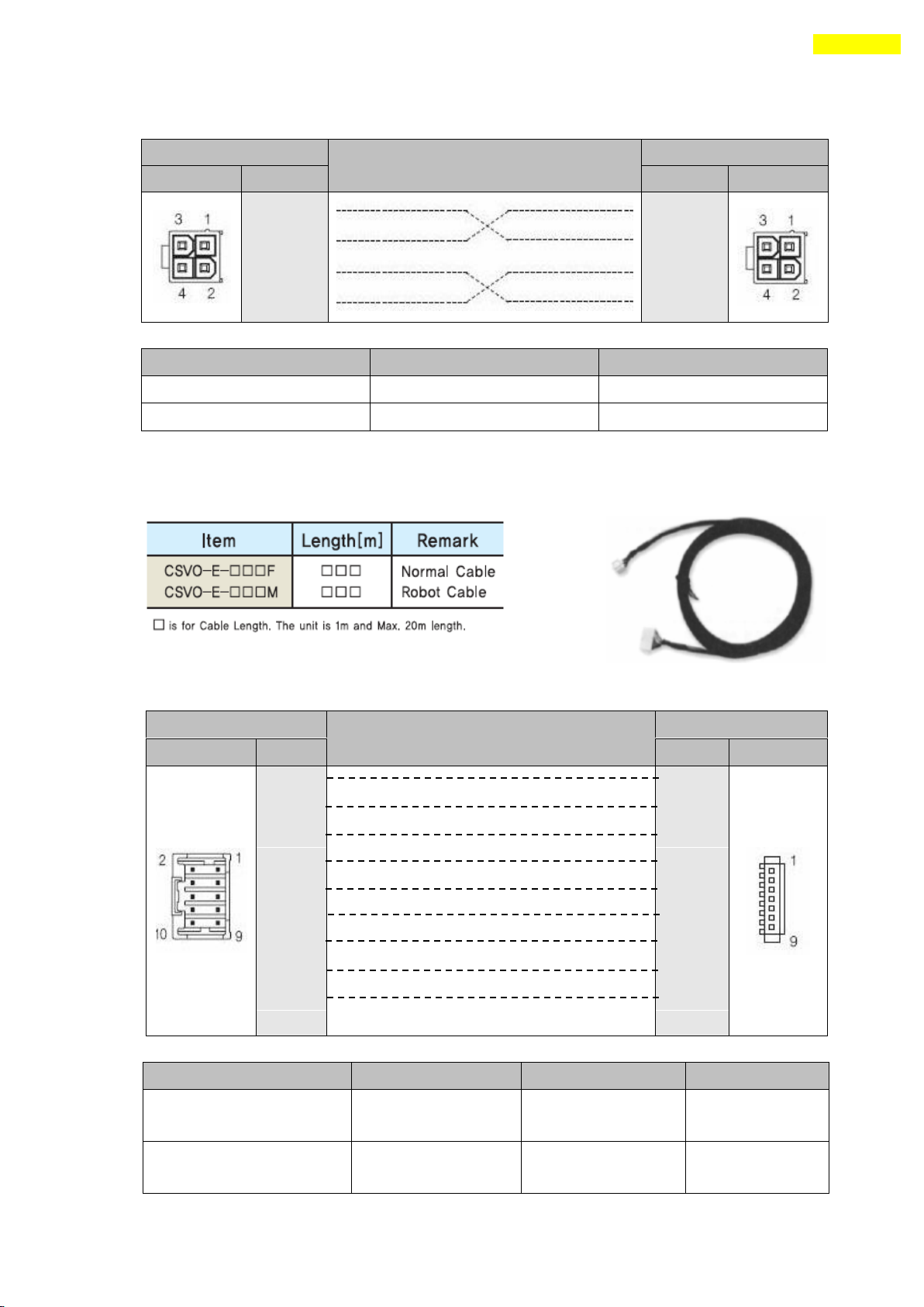
98
Appendix
Drive Connector(CN3)
Cable Connection
Motor Connector
Pin Layout
Pin No.
Pin No.
Pin Layout
1 1
2
2
3
3
4
4
Item
Specification
Maker
Housing
5557-04
MOLEX
Terminal
5556
MOLEX
Drive Connector(CN2)
Cable Connection
Motor Connector
Pin Layout
Pin No.
Pin No.
Pin Layout
1
1
2 2
3 3
4 4
5 5
6 6
7 7
8 8
9 9
Type
Item
Specification
Maker
Drive Connector (CN2)
Housing
Terminal
51353-100
56134-9000
MOLEX
MOLEX
Motor Connector
Housing
Terminal
SMP-09V-NC
SHF-001T-0.8BS
JST
JST
Wiring Diagram
Connector Specification
■ Extension cable for Encoder
Available to extend the distance between the encoder and Ezi-SERVO Plus-R.
Refer to ② of 「5.2 Controller Configuration」.
Wiring Diagram
Connector Specification
www.fastech.co.kr
Page 99
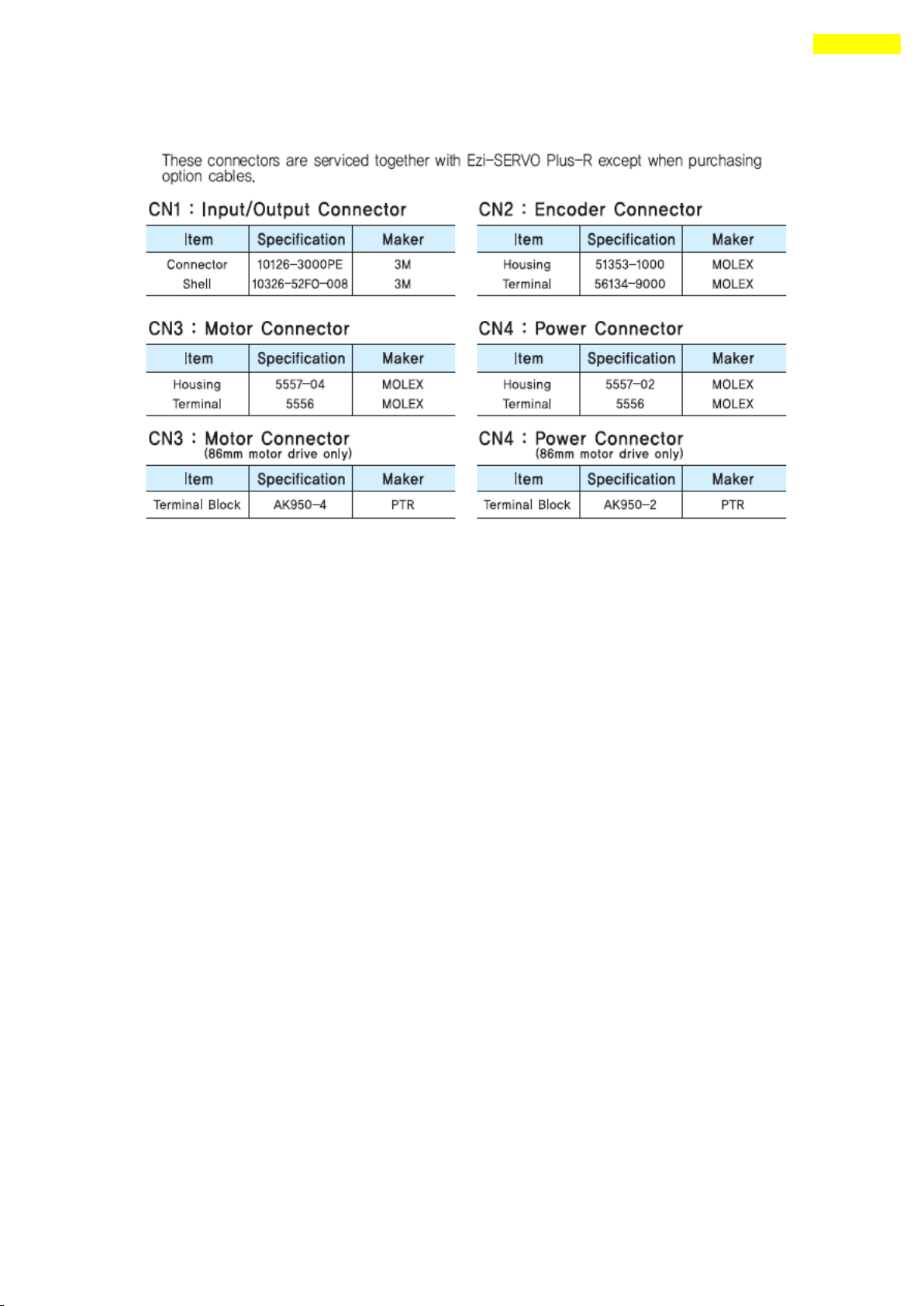
99
Appendix
■ Connector for cabling
www.fastech.co.kr
Page 100
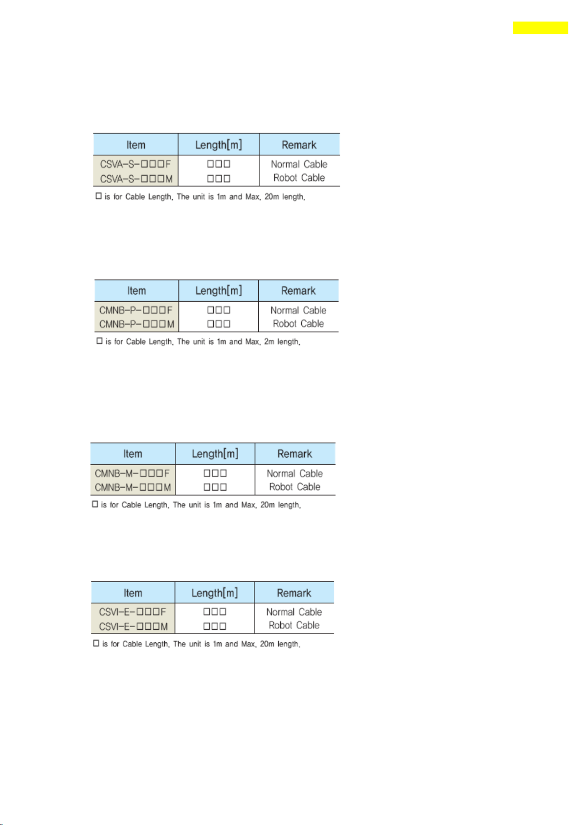
100
Appendix
Option for Motor Drive : Ezi-SERVO-PR-MI only
■ Cable for Input/Output Signal
Available to connect between Control System and Ezi-SERVO-PR-MI.
Refer to ① of 「5.2 Controller Configuration」.
■ Cable for Power
Available to connect between Power and Ezi-SERVO-PR-MI.
Refer to ④ of 「5.2 Controller Configuration」.
■ Extension Cable for Motor
Available to extended connection between motor and Ezi-SERVO-PR-MI.
Refer to ③ of 「5.2 Controller Configuration」.
■ Extension cable for Encoder
Available to extend the distance between the encoder and Ezi-SERVO-PR-MI.
Refer to ② of 「5.2 Controller Configuration」.
■ Connector for cabling
These connectors are serviced together with Ezi-SERVO-PR-MI except when purchasing
Option cables.
www.fastech.co.kr
 Loading...