

Page 1
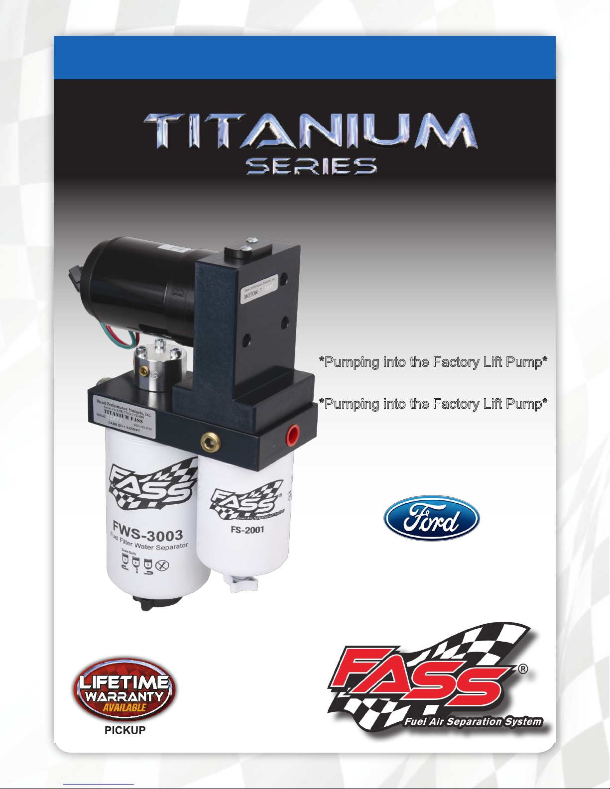
INSTALLATION MANUAL
APPLICATION:
T F12 095G (95gph @ 15psi)
Powerstroke 7.3L 1999-2003
*Pumping into the Factory Lift Pump*
Powerstroke 6.0L 2003-2004
*Pumping into the Factory Lift Pump*
Page 2
Dear Valued Customer,
“Made in the USA” is not just a slogan at FASS; it‟s what we live by! FASS is not only
assembled in the USA but 98%+ of the FASS product is manufactured in the USA, helping to employ Americans and strengthen America. At FASS, we scrutinize our suppliers and demand the
highest quality American-made components. However, this does come at a price, which is one of
the main reasons FASS products are more expensive than the competition. Remember price does
not dictate quality but quality does dictate price! Here at FASS, we believe it‟s worth the commit-
ment and will continue this practice to support America! Our competition is doing exactly the opposite by using foreign-made components.
Building extremely “High-Quality” fuel products is our business. We concentrate all of our
efforts in this arena. No one else is as specialized as FASS in what we do! This is one of the ingre-
dients to insure you are running with the “Highest-Quality” fuel system in the world! We have implemented very rigorous testing procedures to provide the “Highest Quality” we have become
known for. Not only is our product superior, but customer satisfaction is #1 at FASS. It is our goal
to provide the best service possible. Our confidence is evident in the products we make as each
product is backed by an industry leading warranty!
Our R & D department, in conjunction with our Dealer Support department, is continually
searching for ways to improve quality, expand our product line, and provide superb support to our
network of dealers so our customers‟ needs and expectations will be exceeded.
To help insure you receive the proper system and customer support at the local level, FASS
has a VIP and Authorized Dealer network representing FASS products. This is one reason you
must purchase through a dealer to comply with our warranty policies. If you do not, there is no
warranty! We recommend you go to www.FASSride.com, click “Find A Dealer”, put in their ZIP
code, select the type of dealer, and see if the company you purchased from is listed. If they are not,
put their phone number in the field below the ZIP code field to see if they are listed. Below these
two fields is a list of “Terminated/Unauthorized” dealers. You may want to review this list. If the
company is not listed or is on the “Terminated/Unauthorized” list, we suggest you return the product immediately to that dealer and call FASS. We‟ll recommend you to the nearest dealer.
VERY IMPORTANT: Make sure to fill out your product registration form and return the
original form to FASS Fuel Systems within 30 days of purchase accompanied with a copy of the
purchase receipt. Complying with these guidelines will qualify you for the Extended Warranty!
See the Owner‟s Manual for full Limitation of Warranty. In the event that the buyer does
not agree with this agreement: the buyer may promptly return this product, in a new and unused
condition, with a dated receipt, to the place of purchase within thirty (30) days from date of purchase for a full refund less shipping.
The installation of this product indicates that the buyer has read and understands the
Limitation of Warranty agreement and accepts its terms and conditions.
3
Page 3
¡WARNINGs!
Read all instructions before starting installation of this product!
Installing the improper FASS Pump can cause severe engine damage.
T F12 095G
bypass it. Because of the higher fuel flow these systems have to offer, you may encounter
problems with the stock fuel module. FASS can solve this issue with a Suction Tube Kit.
Secure vehicle from ROLLING!
Use caution when drilling. Steer clear of any electrical wires , air lines or other damageable
components.
FASS Recommended Application
Powerstroke 1999-2004 with stock - moderate horsepower modifications
Note: This pump was designed to feed your stock electrical lift pump, do not attempt to
Consult vehicle’s manufacturers’ instructions concerning the electrical system before at-
tempting any electrical connections.
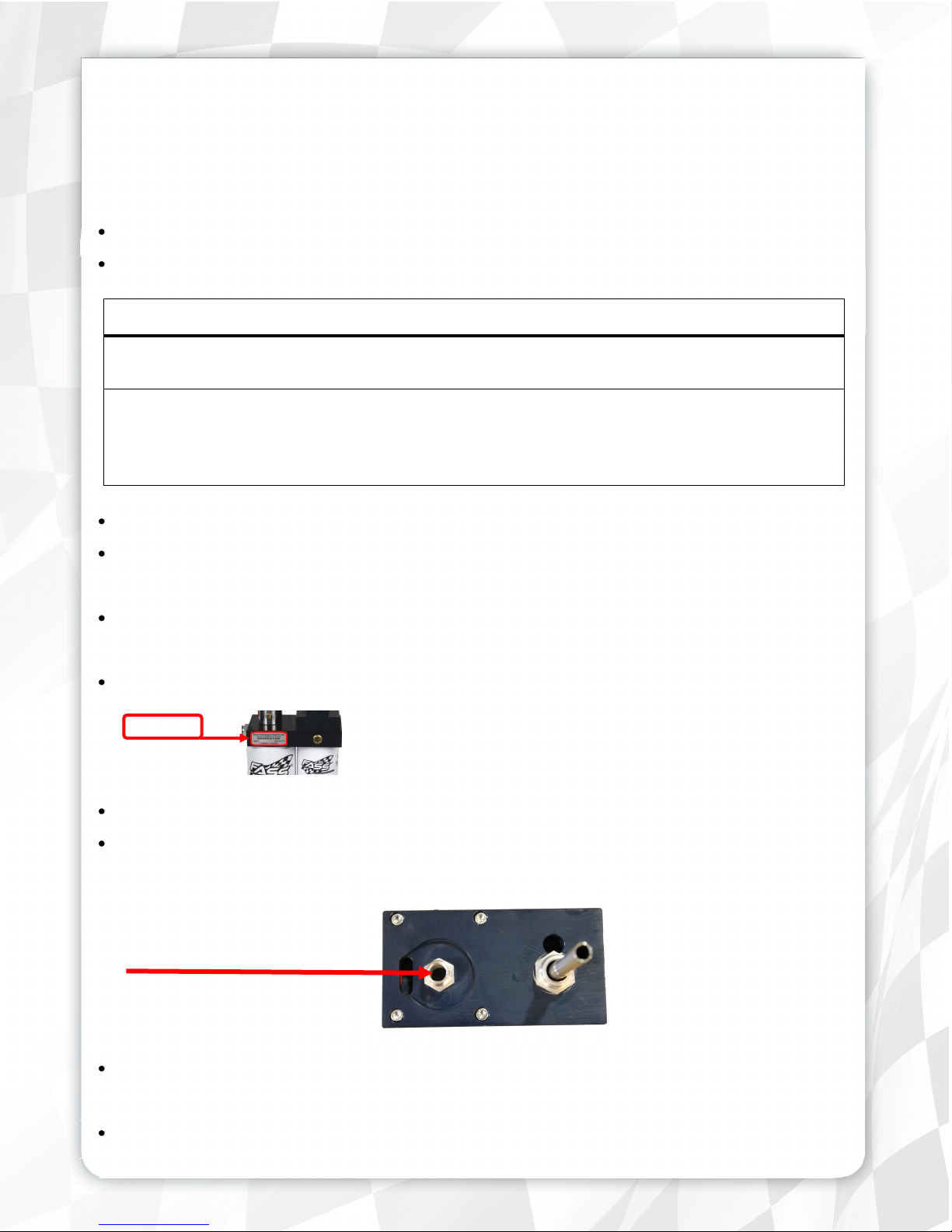
Be sure that the serial # on this installation manual matches that of the outside of the box.
Serial #
Flush and clean all brass fittings and fuel line from debris
Keep debris from entering the internals of the system during installation. Getting debris in
the water separator nipple can lock up the motor. If the motor does lock up from debris call
FASS for technical assistance.
Wear safety glasses when operating power tools such as drills and grinders or when using a
punch or chisel.
Properly secure lines to prevent chaffing.
4
Page 4
INSTALLATION MANUAL
Follow these steps to ensure a simple installation of your new
FASS TITANIUM FUEL SYSTEM
1. Inventory the package components completely. Notify the place of purchase imme-
diately of any parts missing or damaged.
2. Read the installation manual completely before attempting installation. Under-
stand how the system operates and read installation recommendations before be-
ginning installation.
3. The installation recommendations contained herein are guidelines. Its important to
understand your vehicles accessories and limitations. Use good judgment and take
in to consideration your vehicles' accessories.
4. For best results in accuracy and efficiency (due to training, communication, and our
relationship with our dealer network), we recommend an Authorized or ViP FASS
Fuel Systems dealer for the installation. They are prepared to install the FASS fuel
pumps with the most efficiency. If a situation/problem arises during the installation,
they are the most prepared for that situation/problem. We are not responsible for
any installation mistakes.
5. Normally, technical issues can be resolved by your dealer‟s service department, as
they can usually inspect the situation physically. If you have any questions or con-
cerns email or call FASS.
6. If any installation procedure is uncertain, contact FASS technical support.
Email [email protected] with the following information:
Your Name, address and daytime phone number
Model
Serial Number
Last 6 of vehicles‟ VIN
Date of purchase
Nature of Your Concern
Call customer service; 636-433-5410 with the following information:
Model
Serial Number
Last 6 of vehicles‟ VIN
Date of purchase
(T F12 095G)
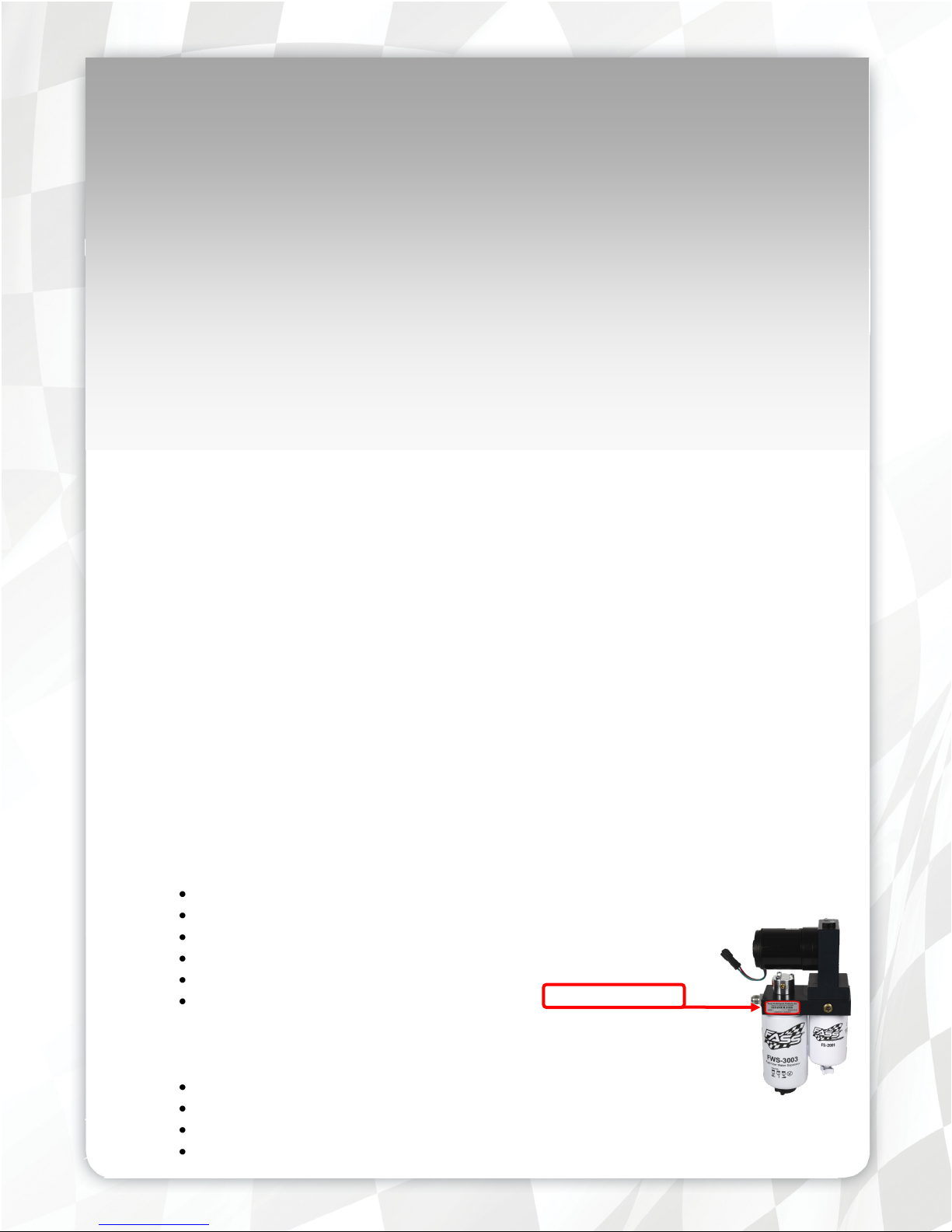
Serial # Found Here….
(T F12 095G)
5
Page 5
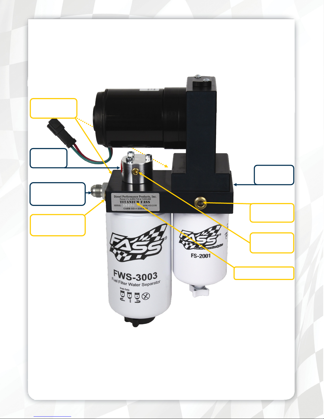
Titanium Series
95 GPH
15 PSI (Approximately)
A fuel pressure gauge is highly recommended to identify fuel filter life and to prevent engine damage!
“H”
Coolant Heater
“E”
To Engine
„T‟
Fuel Inlet
„R‟
Fuel Return to Tank
2nd
Electric Heater Port
Installation
Step 1: Install Electrical Harness
Step 2: Prepare Suction and Return Lines
Electric Heater
Port
„G‟
Fuel Pressure
Serial Number Location
Step 3: Mount Fuel System
Step 4: Install Fuel Line
Step 5: Check Installation
6
Page 6
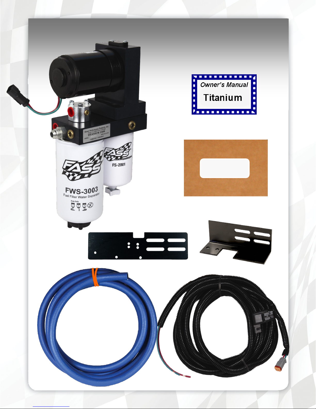
Contents
MP-9023
FL-1001 x15‟
BR-2001
FB-2001
WH-1001
7
Page 7
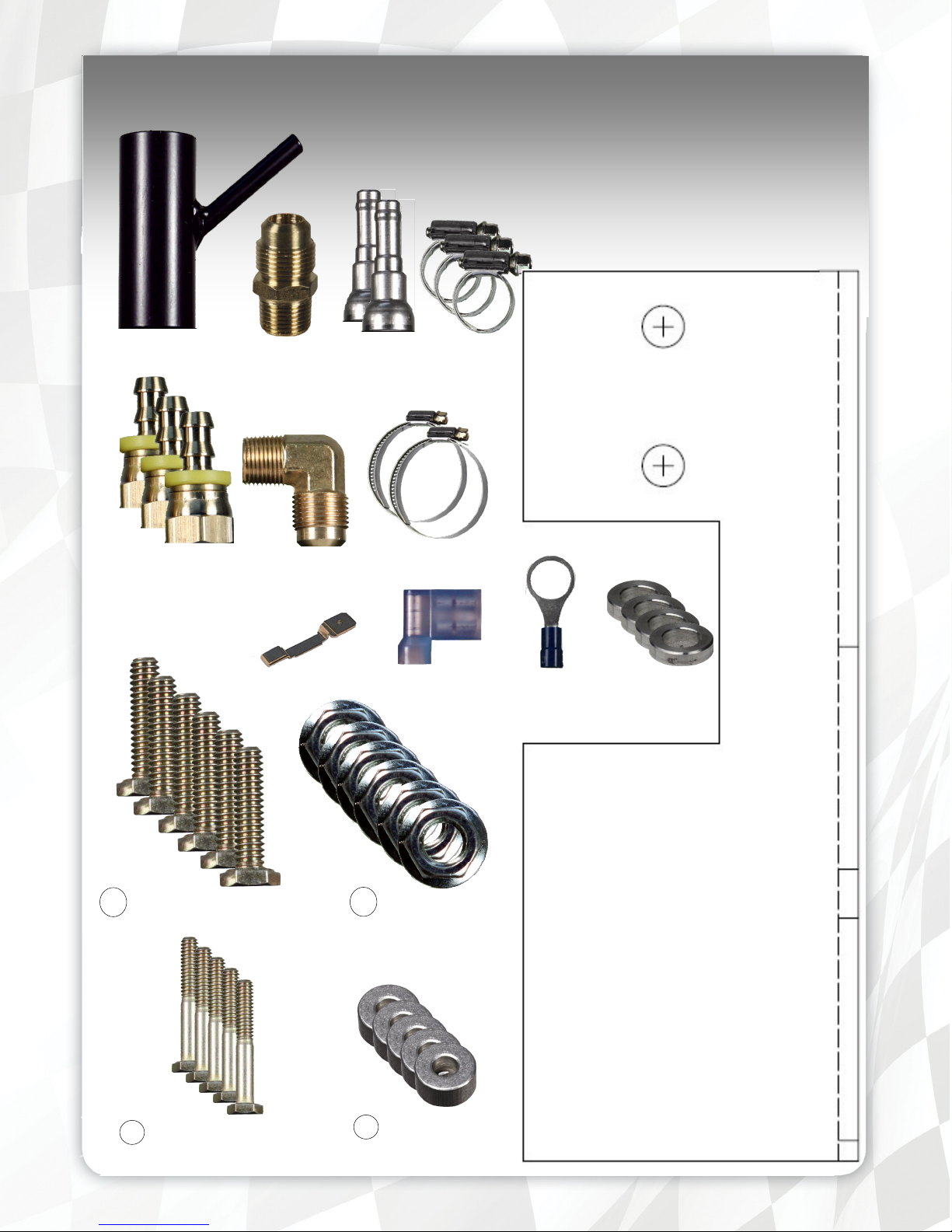
Mounting Package Contents
RM-1002
PL-1002
10-298
10-299
Fuse Tap
QD-1001
HC-1004
Flag Terminal
HC-1001
Ring Terminal
WA-1001C
6 Hex Bolt 3/8” -16x 1 1/4”
5 Hex Bolt 1/4”-20x1.25”
6 Locking Nut 3/8”
5 WA-2001
8
Page 8
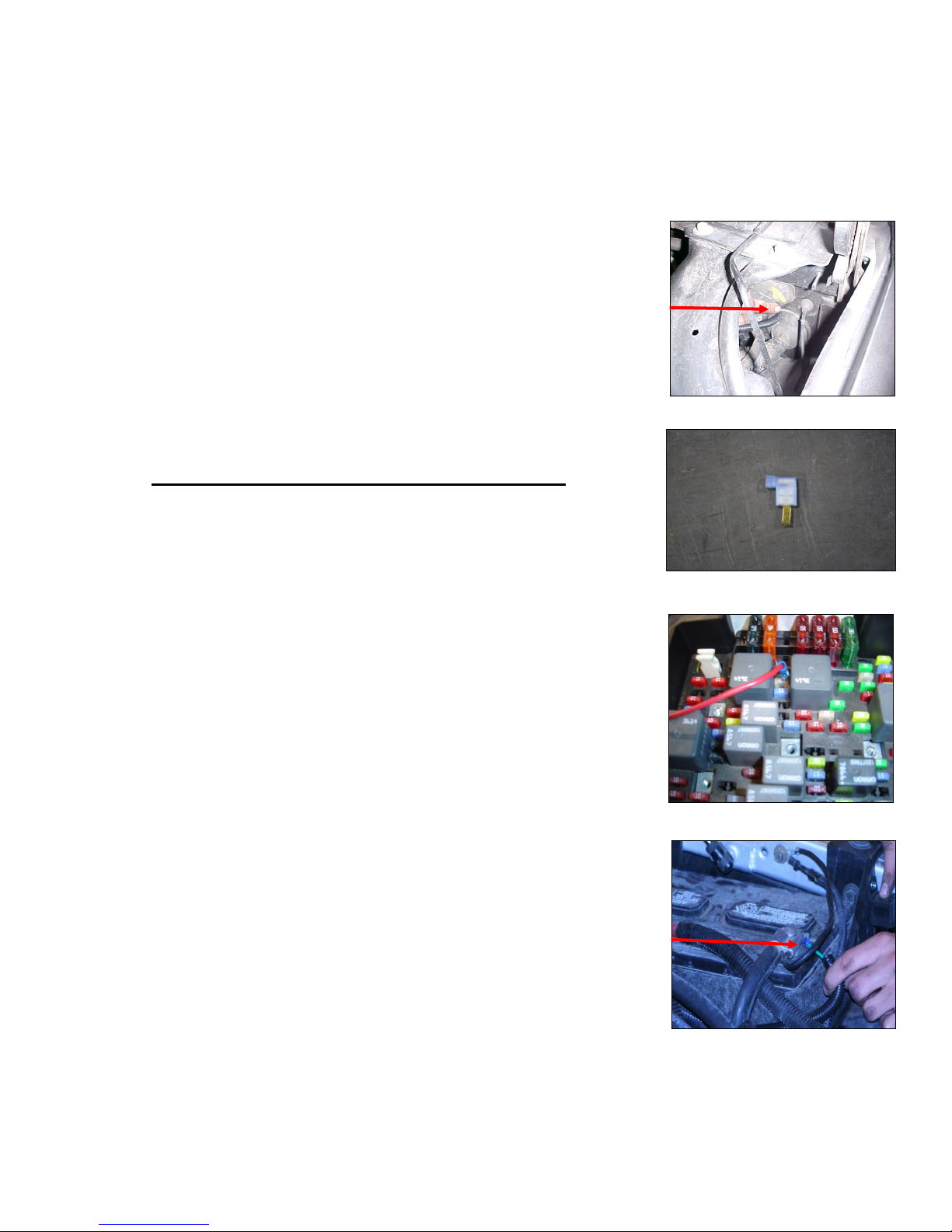
Step 1: Install Electrical Harness
Note: The installation of the electrical harness is done first, allowing power to be applied to the pump
for lubrication purposes later in the installation.
a. The red wire of the WH-1001 wire harness will travel thru the rubber
grommet in the firewall or into the fuse panel in the engine compartment.
Note: Connect the fuse tap to the hot side of the fuse
b. Use a test probe to locate the “hot side” of the circuit in the fuse block.
c. Using the fuse tap & flag terminal, connect the red lead to a terminal on the
circuit board that is “hot” when the key is on.
Note: The use of a corrosion preventative on electrical connections is recommended.
d. Green wire must be connected to a clean ground without being exposed to
any corrosion, preferably the negative battery terminal. Secure fuse block in
a location protected from outside elements.
Note: Completion of this step will be addressed in the Mounting Step 3.
e. Route wire harness along frame rail to mounting location of pump.
9
Page 9
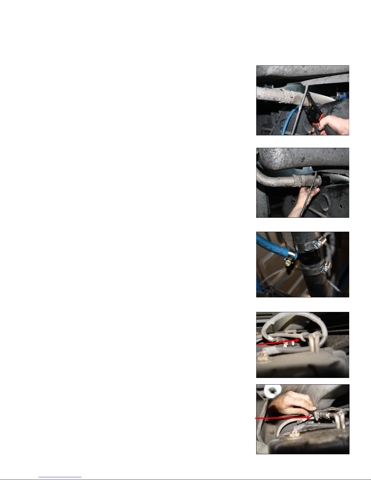
Step 2: Prepare Suction and Return Line
Caution: make sure there is enough tube on each side of the cut to insert the RM-1002 and to place the hose
clamps.
a. Mark location on the filler tube that allows you to install RM-1002. Cut
tube.
b. Position RM-1002 with the junction pipe aiming to outside of bed. Connect
rubber and RM-1002 using both HC-1004‟s but do not tighten.
c. Using a HC-1001 connect FL-1001 to the junction of RM-1002.
d. Disconnect factory suction line by pinching in on the side tabs. Thoroughly
clean this suction port .
e. Insert QD-1001 and clamp into opposite end of fuel line. Oil O-rings inside
QD-1001 and slide onto factory suction port until you hear a click. Loop
fuel line over frame. Do not cut at this time.
10
Page 10
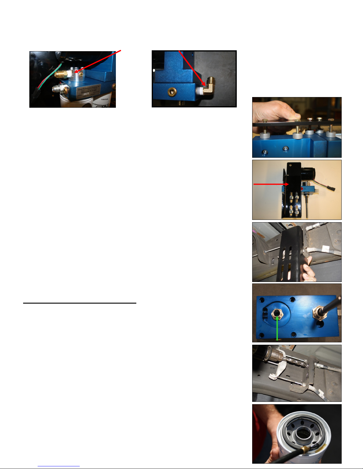
Step 3: Mount Fuel System
a. Using thread tape, install the 10-298 into “E” and the 10-299 into the “T” port (on opposite end).
b. Attach BR-2001 to back of system using 5 1 1/4” Hex bolts and WA-2001
spacers. Torque to 110in/lbs.
c. Placing the WA-1001C‟s between the FB-2001 & the BR-2001, assemble
the FASS pump brackets together. Hold pump up to the mounting location
for rough fitting. Once location is established, use template on back of manual to accurately mark drill points. As seen in next step.
d. Position the pump assembly at the mounting location (emergency brake
cable bracket) check for fit. Once location is established, use template lo-
cated on the contents page to accurately mark drill points.
Note - Before Mounting in Position: Route wire harness along frame rail to
mounting location. Plug female plug of the FASS harness into pump. Turn key
on. With pump operating, liberally spray WD-40 (or equivalent) into „T‟ port
lubricating gear.
e. Pre-drill holes. Final drill with 3/8” bit. Mount pump, level, tighten all
bolts.
f. Apply motor oil to gasket located on filters. Attach to system and hand
tighten.
11
Page 11
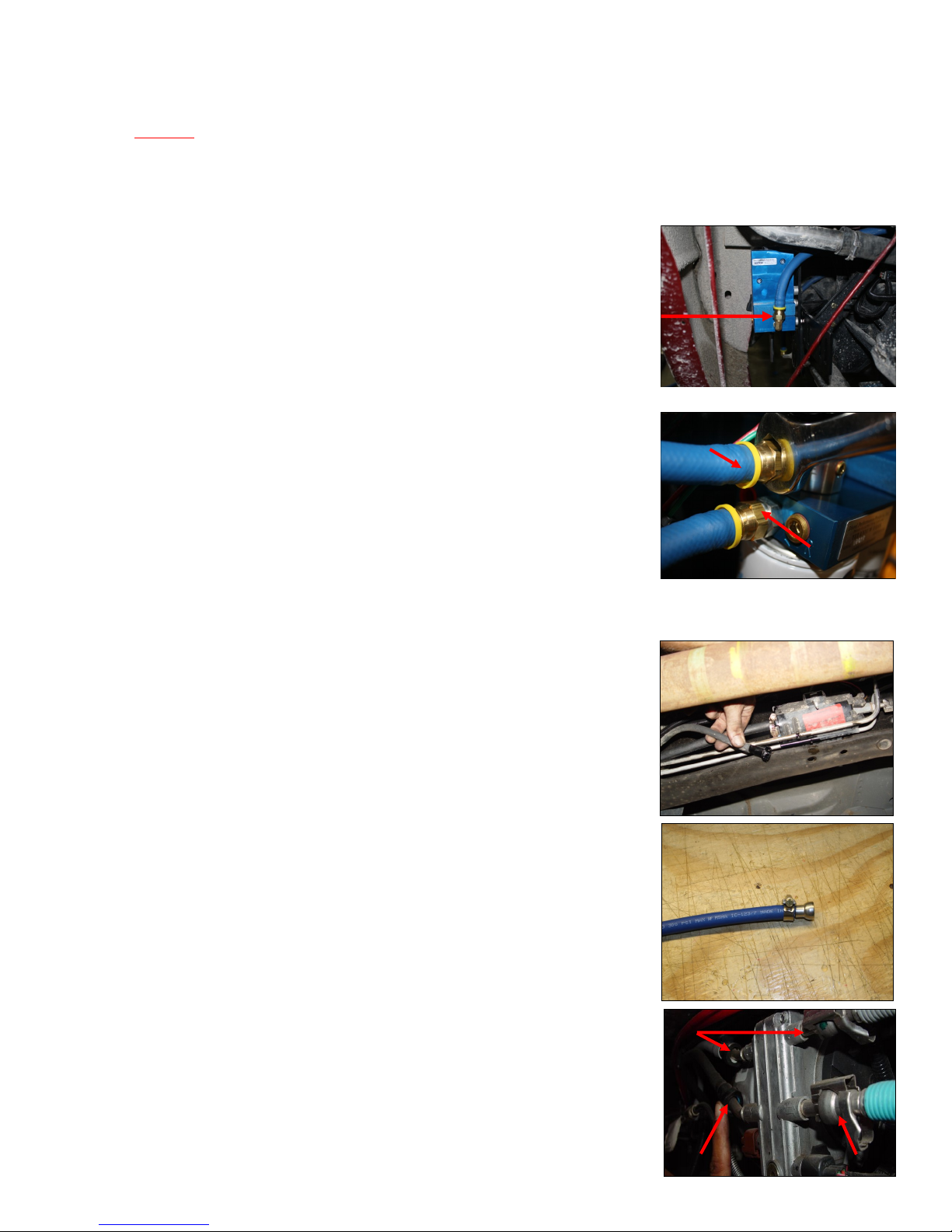
Step 4: Installing Fuel Line
Caution: Do Not use sealant on AN fittings. Only use sealant on threads installed into pump assembly.
Note: Hose clamps are not recommended for push lock fittings. They will hold up to 300psi!
Note: Use oil on fittings and inside fuel line when installing Push-Lok fittings.
a. Route suction line to „T‟ port . Cut FL-1001 to needed length and insert PL-
1002 using oil. Connect to 10-299 in ‟T‟ port . Torque to 18 ft./lbs.
b. Route fuel line from the Return Manifold in the filler neck to the „R‟ port on
the FASS system with a gentle bend. Cut and attach the PL-1002 fitting to
the hose. Use oil. Attach fitting to the „R‟ port. Do not use any sealant.
Torque to 18 ft/lbs.
c. Insert PL-1002 in remaining fuel line. Connect to the „E‟‟ port of the FASS
system. Use oil. Torque to 18 ft./lbs. Route this line up to the area of the
factory fuel pump.
E
R
d. Connect fuel line from the FASS system to the factory fuel pump.
1999-2002 with 7.3L Powerstroke
Remove inlet fuel line to factory fuel pump. Route fuel line from „E‟ port of
the FASS system to inlet of factory fuel pump., cut to length. Slide clamp and
fuel line over inlet of factory fuel pump. Tighten.
2003-2004 with 6.0L Powerstroke
Using a 3/8” hose clamp install the QD-1001 into the fuel line. Oil O-rings inside Quick Disconnect.
Return
Pinch in tabs of the inlet fuel line fitting and remove the inlet fuel line from the
factory fuel pump. Slide QD-1001 onto inlet fuel port of factory fuel until you
hear it click.
12
Inlet
Outlet
Page 12

Step 5: Review Installation
Blow out any open lines/cover any open ports
Bolts and fasteners properly tightened?
Electrical harness and fuel lines secured and properly tightened?
Has the system been primed?
1. Turn key to the ignition position, turning on the FASS pump.
2. While the pump is running, loosen the fuel filter just enough to break the gasket seal. Once the tone
of the pump changes, quickly retighten filter.
Check for leaks.
Start the engine (you will hear the system running)
Recheck all fluid and filter connections for leaks
Fill out product registration, attach receipt of purchase and mail to:
FASS Fuel Systems
16240 State Hwy O, Suite B
Marthasville, MO 63357
13
Page 13

14
 Loading...