

APPLICATION:
T 125G (125gph @ 45psi)
INSTALLATION MANUAL
CLASS 1-CLASS 8
*Requires a Fuel Line Kit*
Dear Valued Customer,
“Made in the USA” is not just a slogan at FASS; it’s what we live by! FASS is not only
assembled in the USA but 98%+ of the FASS product is manufactured in the USA, helping to employ Americans and strengthen America. At FASS, we scrutinize our suppliers and demand the
highest quality American-made components. However, this does come at a price, which is one of
the main reasons FASS products are more expensive than the competition. Remember price does
not dictate quality but quality does dictate price! Here at FASS, we believe it’s worth the commitment and will continue this practice to support America! Our competition is doing exactly the opposite by using foreign-made components.
Building extremely “High-Quality” fuel products is our business. We concentrate all of our
efforts in this arena. No one else is as specialized as FASS in what we do! This is one of the ingredients to insure you are running with the “Highest-Quality” fuel system in the world! We have implemented very rigorous testing procedures to provide the “Highest Quality” we have become
known for. Not only is our product superior, but customer satisfaction is #1 at FASS. It is our goal
to provide the best service possible. Our confidence is evident in the products we make as each
product is backed by an industry leading warranty!
Our R & D department, in conjunction with our Dealer Support department, is continually
searching for ways to improve quality, expand our product line, and provide superb support to our
network of dealers so our customers’ needs and expectations will be exceeded.
To help insure you receive the proper system and customer support at the local level, FASS
has a VIP and Authorized Dealer network representing FASS products. This is one reason you
must purchase through a dealer to comply with our warranty policies. If you do not, there is no
warranty! We recommend you go to www.FASSride.com, click “Find A Dealer”, put in their ZIP
code, select the type of dealer, and see if the company you purchased from is listed. If they are not,
put their phone number in the field below the ZIP code field to see if they are listed. Below these
two fields is a list of “Terminated/Unauthorized” dealers. You may want to review this list. If the
company is not listed or is on the “Terminated/Unauthorized” list, we suggest you return the product immediately to that dealer and call FASS. We’ll recommend you to the nearest dealer.
VERY IMPORTANT: Make sure to fill out your product registration form and return the
original form to FASS Fuel Systems within 30 days of purchase accompanied with a copy of the
purchase receipt. Complying with these guidelines will qualify you for the Extended Warranty!
See the Owner’s Manual online at www.FASSride.com for full Limitation of Warranty. In
the event that the buyer does not agree with this agreement: the buyer may promptly return this
product, in a new and unused condition, with a dated receipt, to the place of purchase within thirty
(30) days from date of purchase for a full refund less shipping.
The installation of this product indicates that the buyer has read and understands the
Limitation of Warranty agreement and accepts its terms and conditions.
¡WARNINGs!
WARNING: Do not tie FASS Return in
with engine return. Back pressure can
cause damage to engine.
Read all instructions before starting installation of this product!
Installing the improper FASS Pump can cause severe engine damage. This unit was not de-
signed to be used on Unit Injected Mechanical Engines. Refer to the FASS kits with UIME
in the model number.
Do Not Remove any factory installed secondary fuel filter! Removal of a factory installed
secondary fuel filter may void the engine manufacturer’s warranty. This is the fuel filter
between the engines fuel pump and the injectors.
Be sure that the serial # on this installation manual matches that of the outside of the box.
Keep debris from entering the internals of the system during installation. Getting debris in
the water separator nipple can lock up the motor. If the motor does lock up from debris call
FASS for technical assistance.
Properly secure lines to prevent chaffing.
FASS Recommended Application
T 125G
Class 1– Class 8, Agriculture, Industrial, Recreational, Hwy and off-road.
Applications requiring fuel flow demands of 45psi and less than 125gph
Use caution when drilling. Steer clear of any electrical wires , air lines or other damageable
components.
Below is a chart of available fuel line kits FASS has to offer. Using one of these kits will
make the installation cost effective and easier. This manual will refer to these FLK #’s
Take caution when producing extra ports. Do only as directed as to be careful not to cause
back pressure to engine return or severe engine damage.
INSTALLATION MANUAL
Follow these steps to ensure a simple installation of your new
FASS TITANIUM FUEL SYSTEM
1. Read the installation manual completely before attempting installation. The instal-
lation of this product indicates that the buyer has read and understands the limita-
tions of the FASS manufacturers warranty agreement and accepts the responsibility
of its terms and conditions.
2. Inventory the package components. Notify the place of purchase immediately of
any parts missing or damaged.
3. The installation recommendations contained herein are guidelines. Use good judg-
ment and take into consideration your vehicles' accessories.
4. For best results in accuracy and efficiency (due to training, communication, and our
relationship with our dealer network), we recommend a ViP FASS dealer for the
installation. They are prepared to install the FASS fuel pumps with the most effi-
ciency. If a situation/problem arises during the installation, they are the most pre-
pared for that situation/problem. DPPI is not responsible for any installation mis-
takes.
5. If you have any questions or concerns that can not be addressed with your dealer,
email or call FASS.
6. If any installation procedure is uncertain, contact FASS technical support.
Email techsupport@FASSride.com with the following information:
:
Your Name, address and daytime phone number
Model
Serial Number
Last 6 of vehicles’ VIN
Date of purchase
Nature of Your Concern
Call customer service; 636-433-5410 with the following information:
Model
Serial Number
Last 6 of vehicles’ VIN
Date of purchase
(T 125G)
Serial # Found
(T 125G)
Titanium Duty Series
125 GPH
45 PSI (Approximately)
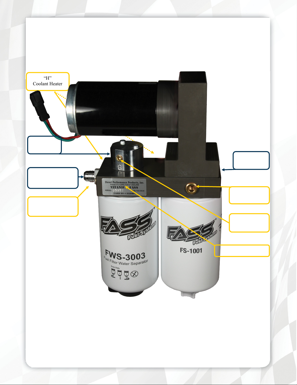
A fuel pressure gauge is highly recommended to identify fuel filter life and to prevent engine damage!
“H”
Coolant Heater
“E”
To Engine
‘T’
Fuel Inlet
‘R’
Fuel Return to Tank
2nd
Electric Heater Port
Installation
Step 1: Install Electrical Harness
Step 2: Prepare Suction and Return Lines
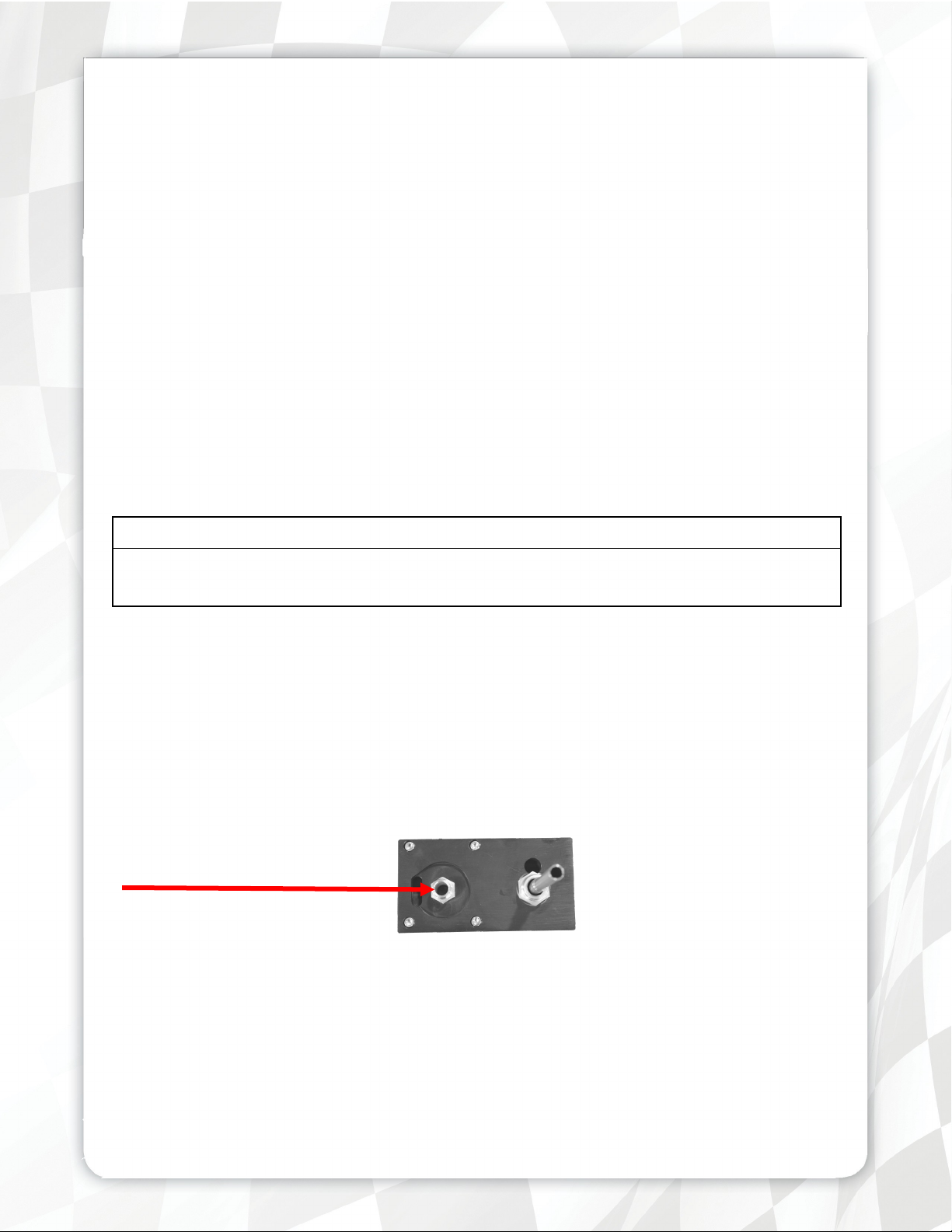
Electric Heater
Port
‘G’
Fuel Pressure
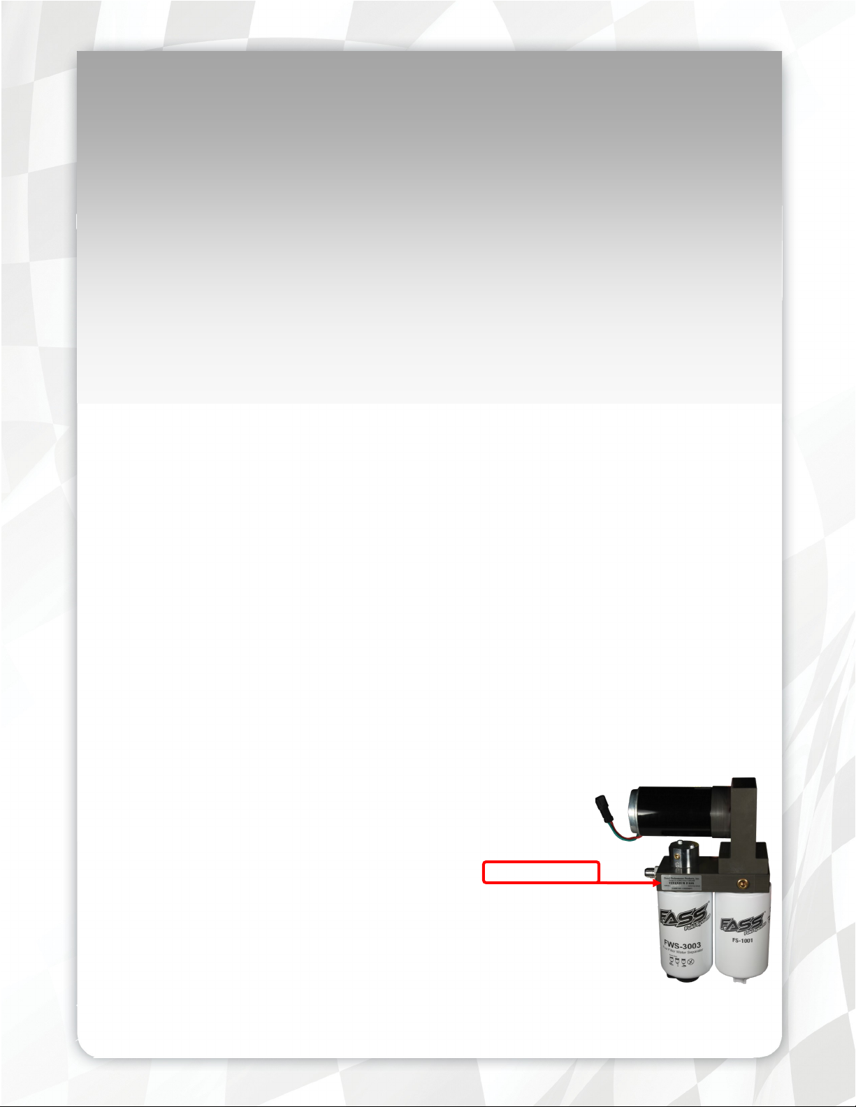
Serial Number Location
Step 3: Mount Fuel System
Step 4: Install Fuel Line
Step 5: Check Installation
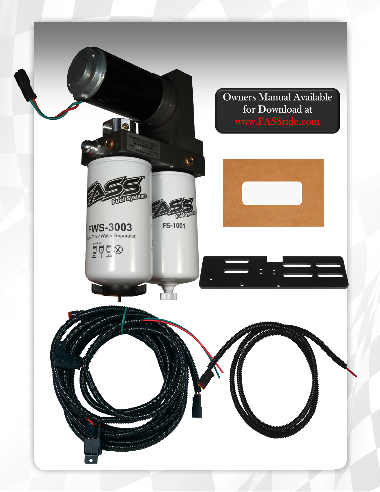
Contents
MP-9050
BR-2001
WH-1005
*WE-1001*
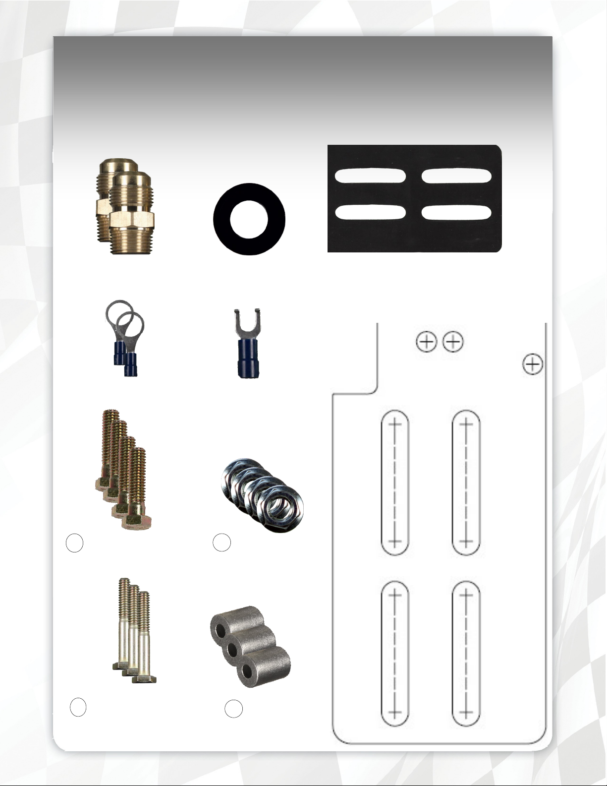
Mounting Package Contents
10-273
Ring Terminal
4 3/8-16”x 1 1/2” Hex Bolt
RS-2684
Spade Terminal
4 Locking Nut 3/8”
RS-1001
3 Hex Bolt 1/4-20 13/4"
Mounting template
3 WA-1001D

The installation of the electrical harness is done first, allowing power to be applied to the pump for
lubrication purposes.
A. Select best location in firewall for passage of wiring harness from cab to engine compartment.
B. Find or drill a 7/8” hole in firewall. Install RS-2684 grommet for ease of installation and protection of
wire harness.
C. Connect WE-1001 wire extension to the WH-1005.
D. Route red wire/ loom of the wire extension through the grommet in the firewall to the ignition or fuse
panel. The use of corrosion preventative spray and dielectric grease is recommended where elec-
trical connection are made..
E. Connect the “Red” lead to the “ON” terminal of the ignition switch or
a terminal on the circuit breaker board that is “hot” when the key is
on. Use a test probe to locate the “hot side” of the circuit in the
fuse block.
F. Using the ring terminals, connect the green wire of the wire harness to the negative post and the red
wire to the positive post of the battery.
G. Secure relay in an upright position, preferably on the firewall out of
the weather.
H. Properly secure all electrical leads and harness.

Some of the photo’s are of a different application, procedures are the same.
A. Remove primary fuel and/or water separator. If primary filter is part of the fuel pump, ignore this step.
Note: Use thread tape on “ALL” male pipe threads, do not use on male flared fittings.
B. Skip this step if primary filter is part of the engine’s fuel pump. If 90° fitting is needed use OEM
fitting (as seen in this photo)
B1. Remove upside down “T” Block pump assembly (Item # 1) by removing the 4 bolts holding it to the
FASS filter base. Pay attention to the O-rings (2) and ball
B2. Remove the fuel manifold (Item #2) and assemble 90° fitting directing it in the correct direction.
B3. Reassemble fuel manifold then pump assembly to FASS filter base making sure all O-rings & the ball
are seated in their proper place. Torque to 110 in./lbs.

Some of the photo’s are of a different application, procedures are the same.
C. Attach BR-2001 to back of system using the spacers and 1/4” bolts. Use the two bottom bolts and the
very top one bolt opening.
D. Position system where it will be mounted. Mark the (4) mounting
points (using the template located on the contents page). Prior holes may be used. Drill these
marked locations with a 13/32 bit.
E. Connect factory plug into the FASS harness. Turn key to “on”. With pump operating, turn pump over,
liberally spray WD-40 (or equivalent) into water separator nipple lubricating the Gerotor.
F. Assemble to frame using the (4) - 3/8” bolts & flange nuts placing the RS-1001 between the frame and
bracket.
G. Apply motor oil to O-rings located on filters. Attach to system and tighten appropriately

For optimal engine performance gains, the return line should return to its own port.
A. Fuel lines, excluding nylon type fuel lines, in excess of 6 years old should be replaced due to interior
lining deterioration. This condition can cause many problems including but not limited to: fuel
starvation, uneven fuel tank levels and etc.
B. When routing the return line from the FASS Fuel System, you will need to first identify your current
fuel system. Now match with the correct fuel line section below and follow the corresponding procedures. Uneven fuel level conditions can occur between the tanks if the pickup/return lines are im-
properly installed.
B1. Most Popular - Usually on 1994 Trucks & Newer including Volvo and Mercedes Engines:
Double Draw/Double Return Line System. FASS fuel line kit (FLK-S03) or Double Vent Return Line
Kit for trucks without the extra port of the fuel tanks(FLK-SO6)should have all of the product to complete this process
B2. 2nd Most Popular - Usually on 1993 Trucks & Older (except 359 Peterbilt - next selection):
Single Draw/Single Return Line System. FASS fuel line kit (FLK-S02) should have all of the product
to complete this process
B3. 359 Peterbilt: Single Draw Out of Cross Over Fuel Line/Single Return Line System
Dual Tank Recommendation:
1st Choice - Convert to a complete Double Draw/Double Return Line System(FLK-S03) or Double
Vent Return Line Kit (FLK-S06).
2nd Choice - Convert to a true Single Draw/Single Return Line System FLK-S02).
B4. DD15 - DD15 Supply/Double Return Fuel Line Kit (FLK-S07) should have all of the product to com-
plete this process

Caution: Do Not use sealant on AN fittings. Only use sealant on threads installed into pump assembly or joining fittings.
Note: No extra ports? - Refer to the option located at the back of the manual.
Return line from
FASS with straight
ends to cross member where the line
will “T” off.
These lines must be the exact length on both sides.
From “T” to each fuel tank with
1-straight fitting &
1-90° fitting on each line.
A. Locate extra bung on the fuel tanks, most KW’s have a 1/4”, Peterbilt have
3/8” or 1/2” extra pipe plug located by the fuel lines at the top of the fuel tank.
Other models may have an extra port some where at the top of the fuel tank.
Remove the plugs and install a –8 AN fitting into each tank. It maybe necessary to use a bushing to adapt fitting to tank.
B. Install (90° or straight) fitting into fuel line using the following procedures: refer to this procedure
when necessary.
B1. Assemble fuel line into female hose fitting (reverse threads), then
apply a modest amount of oil to the interior lining.
B2. Secure female end in vise.
B3. Oil male JIC swivel (90° or straight) and assemble into female end.
B4. The male portion should tightened all the way, as seen.

C. Assemble the “T” using (1) 3/8 NPT ‘T’, (2) -8 ANx3/8 MPT & (1) -8 ANx3/8
MPT 90° as seen in the photo.
Note: Hose clamps are not recommended for push lock fittings. They
will hold up to 300psi! Use oil on fittings and inside fuel line when in-
stalling Push-Lok fittings
D. Attach the line completed in Step 4b to the return port of the FASS labeled with
an “R”. Route to the center of the nearest cross member aligned with the ports in
the fuel tank being used for return fuel. Measure & mark this line as it will connect to the 90° fitting of the “T” in this location.
E. Cut the fuel line and assemble a –8 AN hydraulic fitting in the opposite end of
the line connecting to the “R” port of the FASS.
F. Assemble a –8 AN hydraulic fitting into one end of the remaining fuel line.
Route this fuel line from straight fitting of the “T” to the return port in the
fuel tank, mark & cut.
G. Caution: Route the side with the exhaust first as it will be necessary to
travel below the frame to avoid the exhaust, each side has to be the exact
same length. Later it will install as seen.
H. Cut the remaining fuel line to the “Exact” same length line as the line in Step 4f.
I. Assemble (1) of each –8 AN 90° & -8 AN Straight into each line addressed in
Steps 4f & 4g.
J. In the same manner as previously covered, route and loosely connect the assem-
bled fuel lines discussed in this section to the appropriate points of connection
including the ‘T’.
K. Torque all connections to 18 ft./lbs. Secure the fuel line and all fittings. Contin-
ue to Step 5

Caution: Do Not use sealant on AN fittings. Only use sealant on threads installed into pump assembly or joining fittings.
Note: No extra ports? - Refer to the option located at the back of the manual.
A. Locate a fuel return port into the fuel tank. Most KW’s have a 1/4”, Peterbilts
have 3/8” or 1/2” extra pipe plug located by the fuel lines at the top of the fuel
tank. Other models may have an extra port some where at the top of the fuel
tank. Remove the plugs and install the –8 ANx5/16 NPT into each tank, it maybe necessary to use a brass bushing.
B. Install –8 AN hydraulic fitting into fuel line using the following procedures: refer to this procedure
when necessary.
B1. Assemble fuel line into female hose fitting (reverse threads), then
apply a modest amount of oil to the interior lining.
B2. Secure female end in vise.
B3. Oil male end of 90° JIC swivel fitting and assemble into female end.
B4. The male portion should tightened all the way, as seen.

Note: Hose clamps are not recommended for push lock fittings.
They will hold up to 300psi! Use oil on fittings and inside fuel line
when installing Push-Lok fittings
C. Attach the line completed in Step 4b to the return port of the FASS labeled
with an “R”. Route to the port in the fuel tank being used for return fuel.
Measure, mark & cut.
D. In the same manner as previously covered, route and loosely connect the fuel
lines discussed in this section to the appropriate points of connection.
E. Torque all connections to 18 ft./lbs. Secure all fuel lines and fittings. Continue to Step 5

A. Attach the fuel supply line from the fuel tank to the FASS using a 10-273L
or one of the fitting from the filter housing removed in step 2. IF fuel sup-
ply line connects directly to engine-the primary fuel filter is not remote
mounted-skip to step C (Usually, not always, on NTC/STC’s and N14’s).
B. Attach the fuel supply line from the FASS to the engine pump using a 10- 273L or
one of the fittings from the filter housing removed in step 2. Once completed, you
are finished with step 5 and you may go directly to step 6.
C. Disconnect fuel line from engine. Connect to “T” port of the FASS.
D. Assemble a –10 AN hydraulic fitting into one end of the #10 fuel line and loosely
connect to either the FASS or the engine.
E. Route fuel line to open port (engine or FASS) measure and cut.
Note: Part # 3915423S from Fleetguard will take the place of the engine mounted
fuel filter.
F. Assemble a –10 AN hydraulic fitting into the cut end. Remember, clocking of the fuel fittings may be
necessary to connect to ports in discussion.
G. Attach the assembled fuel line to the FASS and engine. CAUTION: IT IS VERY IMPORTANT TO
BLOW THIS FUEL LINE OUT BEFORE FINAL ASSSEMBLY TO ENGINE!!
Note: Secure all fuel lines with cable ties. Cable ties are an economical way to prevent the
possibility of problems occurring!

Caution: Do Not use sealant on AN fittings. Only use sealant on threads installed into pump assembly or joining fittings.
Return line from
FASS with straight
ends to cross member
where the line will
“T” off.
From “T” to each fuel tank with
2-straight fittings on 2 of the lines going to the Vent Line &
1-90° fitting on Return line connecting to the FASS
These lines must be the exact length on both sides.
A. Assemble fuel line into female hose fitting (reverse threads), then
apply a modest amount of oil to the interior lining.
B. Secure female end in vise.
C. Oil male JIC swivel (90° or straight) and assemble into female end.
D. The male portion should tightened all the way, as seen.
E. Assemble the “T” using (1) 3/8 NPT ‘T’, (2) -8 ANx3/8 MPT & (1) -8 ANx3/8
MPT 90° as seen in the photo.

F. Attach the line completed in Step 4b to the return port of the FASS labeled with
an “R”. Route to the center of the nearest cross member aligned with the ports in
the fuel tank being used for return fuel. Measure & mark this line as it will connect to the 90° fitting of the “T” in this location.
G. Cut the fuel line and assemble a –8 AN hydraulic fitting in the opposite end of
the line connecting to the “R” port of the FASS.
H. Assemble a –8 AN hydraulic fitting into one end of the remaining fuel line.
Route this fuel line from straight fitting of the “T” to the return port in the fuel
tank, mark & cut.
I. Caution: Route the side with the exhaust first as it may be necessary to travel below the frame to
avoid the exhaust, each side has to be the exact same length. Later it will install as seen.
J. Cut the remaining fuel line to the “Exact” same length line as the line in Step 4f.
K. Assemble (2) of each -8 AN Straight into each side of the line addressed in Steps 4f & 4g.
L. In the same manner as previously covered, route and loosely connect the assembled fuel lines discussed
in this section to the appropriate points of connection including the ‘T’.
M. Torque all connections to 18 ft./lbs. Secure the fuel line and all fittings. Continue to Step 5

N. Locate Fuel Tank Vent Line and remove vent and vent line from tank. Thread tape reducer on both
ends and install reducer into tank. Once reducer has been secured install “T” onto reducer and secure.
Thread tape bushings and install them on the “T” . NOTE: Not all configurations will be able to be
assembled this way.Install the vent line on the top portion of the “T” and the FASS return line into the
middle of the “T”. Repeat previous steps on other tank to install the Double Vent Line Return Kit.
Fuel Tank Vent Line
FASS Return
Fuel Tank
O. The below picture illustrates the configuration previously mentioned..

A. Bolts and fasteners properly tightened?
B. Electrical harness and fuel lines secured and properly tightened?
C. Has the system been primed, refer to owners manual?
D. Check for leaks.
E. Start the engine
F. Recheck all fluid and filter connections for leaks
G. Product registration filled out and ready to be mailed or faxed.
A. Most Preferred & Easiest
1. Drill and tap a 3/8”fpt in the thicker band of aluminum as seen.
2. If possible, install the fuel tank vent in this port and connect the FASS
(Bung fitting)
B. Weld a Bung Fitting
1. Fire Hazard, must be accomplished by a professional.
To assist with priming your FASS pump crack the FWS-3003. Put power to the FASS pump to
activate the pump. When the tone of the pump changes you can tighten up the fuel filter. If you
need a video of the priming process go to www.FASSride.com.
Note: The Red Plastic Plugs located in the “H” ports can stay in place fuel will not flow
through these ports. Coolant can be plumbed into these ports to heat the fuel in the Winter
months.

Note: O-Ring must be put back on suction side of pump. Failure to do so can result in
priming issues, cavitation, or pressure loses.
Fuel Filter –Install FWS-3003
on side of pump with draw tube
in the middle of the filter nipple.
Water Separator Filter –Install FS-1001 on water
separator nipple without the draw tube. Make sure
to insert O-Ring provided on nipple.

Disclaimer: To help insure you receive the proper system and customer support at the local level, FASS has a VIP and
Authorized Dealer network representing FASS products. This is one reason you must purchase through a dealer to comply
with our warranty policies. If you do not, there is no warranty! We recommend you go to www.FASSride.com, click “Find
a Dealer”, put in their ZIP code, select the type of dealer, and see if the company you purchased from is listed. If they are
not, put their phone number in the field below the ZIP code field to see if they are listed. Below these two fields is a list of
“Terminated/Unauthorized” dealers. You may want to review this list. If the company is not listed or is on the
“Terminated/Unauthorized” list, we suggest you return the product immediately to that dealer and call FASS. We’ll recommend you to the nearest dealer.
Diesel Performance Products, Inc. (hereafter “SELLER”) gives Limited Warranty as to description, quality, merchantability, fitness for any product’s purpose, productiveness, or any other matter of SELLER’S product sold herewith. The SELLER shall be in no way responsible for the product’s open use and service and the BUYER hereby waives all rights other
than those expressly written herein. This Warranty shall not be extended or varied except by a written instrument signed by
SELLER and BUYER.
When MANUFACTURER receives the “ORIGINAL” PRODUCT REGISTRATION form with a copy of the “BILL
OF SALE/SALES RECEIPT” within 30 days of the sale, then the following applies! The Warranty will then and only
then be validated to that of which typically accompanies your unit for your specific application from the date of sale or for
recommended service life and limited solely to the original purchaser and/or vehicle and parts contained within the
product’s kit. This warranty does not cover normal wear on consumable items such as but not limited to filters, fuel line,
wire harness & etc. The warranty does not cover seized gears due to lack of filtration. Warranty is voided if used with other
than diesel fuel. Returned items will arrive prepaid to the place of purchase. Diesel Performance Products, Inc. will repair,
without cost, any product found to be defective during the warranty period; parts only, or at its option, will replace such
products in exchange for the product. Repair or replacements are warranted for the remainder of the original warranty period. All Warranty claims are subject to approval by Diesel Performance Products, Inc.
A Return Material Authorization (RMA) number must be obtained before any product is to be returned to Diesel
Performance Products, Inc. for warranty consideration, repair or product return. Requests for product returns must
be offset by an equal value order. Return parts must be completed and in resalable condition. No returns after 30 days.
The following information is required to obtain a RMA number before returning product:
Your Name, Address, and Phone Number’s
Model and Serial Number (Not Motor Number) Example: Model HD Series, Serial: 00125966
VIN Number of Vehicle
Date of Purchase
Nature of Problem
RMA and Product Serial Number must be on all paperwork and correspondence. Failure to obtain the required information
or paperwork will result in $25.00/item penalty and delay or denial of any warranty claim.
Under no circumstances shall the SELLER and/or MANUFACTURER be liable for any labor charged or travel time incurred in diagnosis for defects, removal, or reinstallation of this product, or any other contingent expenses.
Under no circumstances shall the SELLER and/or MANUFACTURER be liable for any damage or expenses insured by
reason of the use or sale of any such equipment. This warranty does not apply to products which Diesel Performance Products, Inc. has determined to have been misused or abused, improperly maintained by the user, or where the malfunction or
defect can be attributed to the use of non-genuine Diesel Performance Products, Inc. parts.
IN THE EVENT THAT THE BUYER DOES NOT AGREE WITH THIS AGREEMENT: THE BUYER MAY PROMPLY
RETURN THIS PRODUCT, IN A NEW AND UNUSED CONDITION, WITH A DATED PROOF OF PURCHASE, TO
THE PLACE OF PURCHASE WITHIN THIRTY (30) DAYS FROM DATE OF PURCHASE FOR A FULL REFUND
LESS SHIPPING.
THE INSTALLATION OF THIS PRODUCT INDICATES THAT THE BUYER HAS READ AND UNDER-
STANDS THIS AGREEMENT AND ACCEPTS ITS TERMS AND CONDITIONS.
Technical Support:
Diesel Performance Products, Inc.
16240 State Hwy O Suite B
Marthasville, MO 63357
636-433-5410

 Loading...