


INSTALLATION MANUAL
APPLICATION:
DRP 04 (110GPH @ 16-18psi)
Dodge Replacement
2003-2004

¡WARNINGs!
Read all instructions before starting installation of this product!
Installing the improper FASS Pump can cause severe engine damage.
FASS Recommended Application
DRP 04
Note: Due to the increase of fuel flow you may encounter a problem with the stock fuel
Secure vehicle from ROLLING!
Use caution when drilling. Steer clear of any electrical wires , air lines or other damageable
components.
Consult vehicle’s manufacturers’ instructions concerning the electrical system before at-
tempting any electrical connections.
Be sure that the serial # on this installation manual matches that of the outside of the box.
Flush and clean all brass fittings and fuel line from debris.
Keep debris from entering the internals of the system during installation. Getting debris in
the “T” port can lock up the motor.
module. Adding a FASS suction tube kit will solve that issue.
Dodge 2003-2004 with stock horsepower modifications
Serial #
Be sure to utilize the inline fuel filter included in this kit, or the equivalent, to prevent a
motor lock up.
Wear safety glasses when operating power tools such as drills and grinders or when using a
punch or chisel.
Properly secure lines to prevent chaffing.

INSTALLATION MANUAL
Follow these steps to ensure a simple installation of your new
FASS DRP
1. Having a retrofitted in-tank life pump slightly changes your needs with the FASS
DRP . You will also need a STK (Suction Tube Kit) from FASS to allow the fuel to
be drawn to the new DRP.
2. Inventory the package components completely. Notify the place of purchase immediately of any parts missing or damaged.
3. Read the installation manual completely before attempting installation. Under-
stand how the system operates and read installation recommendations before be-
ginning installation.
4. The installation recommendations contained herein are guidelines. Its important to
understand your vehicles accessories and limitations. Use good judgment and take
in to consideration your vehicles' accessories.

DRP Series
110 GPH
16-18 PSI (Approximately)
A fuel pressure gauge is highly recommended to identify fuel filter life and to prevent engine damage!
“E” To Engine
Mounting
Bracket
Weep Hole
Serial #
Installation
Step 1: Remove Factory Lift Pump
Step 2: Mount Pump
Step 3: Install Fuel Line
Step 4: Review Installation
‘T’
Fuel Inlet Port

Contents
FF-3270
FB-4001
FL-1001X 3’
BW-4001
BF-4001 QD-1001 DIPF-1001 PL-1003
FP-1001
WE-1007
HC-1001
Hex Bolt 5/16-18x1/2 Self Tapping Screws
TEMPLATE
BB-4001

Requires a FASS suction tube kit if truck has been retrofitted with an in tank fuel pump.
What you will need:
Angle Drill and Drill Bits
Air Ratchet & Sockets
Metric Wrenches
Allen wrenches or sockets
Razor Knife
Factory Lift Pump
A. Disconnect battery before beginning installation. Unplug factory
lift pump electrical connection and drain factory filter housing by
rotating the yellow drain valve counter-clockwise (towards you).
Use a drip pan under factory filter housing to catch excess
Slightly loosening the black lid may help with faster draining.
B. Disconnect factory fuel pump from the side of the factory filter
housing using a 5mm Allen head socket. Keep the top two Allen
bolts and the O-ring from the inlet port. These will be re-used.
C. Disconnect the factory feed line at the frame by pinching in on the
blue tabs. The factory lift pump can now be lifted out and removed. Remove the blue locking tab from the factory fuel line
and discard.

NOTE: Before installing fittings make sure to inspect for burs or flare imperfections.
When cutting fuel line make sure to blow out line to keep debris from moving forward.
A. Attach the FB-4001 bracket to the DRP using the supplied 5/16”
Hex head bolts. Locate the DRP between the driver’s side frame
rail and starter and check for clearances. When locating the
DRP, make sure there is clearance from any moving parts including suspension, steering, and aftermarket components.
Using the template or bracket, mark the 3 mounting holes to the
frame. Remove bracket from DRP.
B. Drill 3 pilot holes at the marked location. Secure bracket to frame
using the provided self-tapping screws.
NOTE: Hose clamps are not recommended for push lock
fittings. They will hold up to 300psi! Use oil on fittings and
inside fuel line when installing Push-Lok fittings
C. Measure from the front of the installed FB-4001 bracket to the
factory fuel line on the frame. Cut the provided FL-1001 fuel line
to length and insert a BF-4001 banjo fitting using oil. Insert the
QD-1001 quick disconnect with a HC-1001 clamp. Measure between the fittings and insert the FF3270 using two HC-1001
clamps making sure the arrow on the filter is in the direction of
the flow.
Note: Inline filter will need to be replaced every 6,000 miles.
D. With the remaining fuel line, insert a BF-4001 using oil. Attach to the outlet port of the DRP with the
supplied banjo bolt using supplied copper washers on each side of the banjo fitting. Point the fuel line
towards the back of the pump and slightly up as shown to clear the mounting bracket. Torque to 18
lbs./ft.
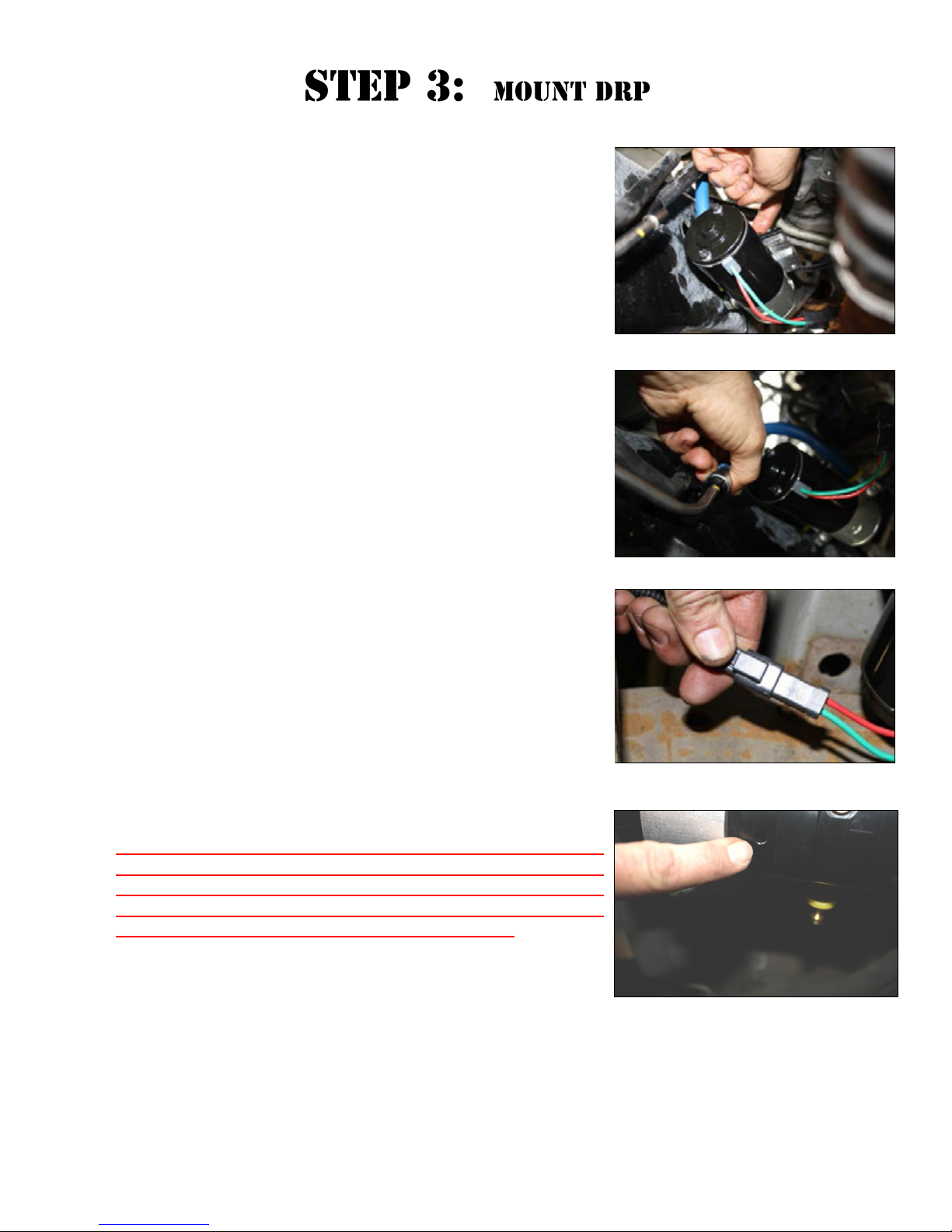
A. Mount DRP/fuel line assembly to the FB-4001 bracket using three
5/16” bolts. The use of Loctite on mounting bolts is recom-
mended. Make sure the outlet fuel line is pointing up to the factory filter housing.
F. Install the short fuel line/filter assembly into the DRP’s inlet port
using the supplied banjo bolt and copper washers. Oil O-rings inside QD-1001 and slide over factory fuel line until you hear a
click. Torque banjo bolt to 18 lbs./ft..
G. Attach WE-1007 wire extension to the DRP plug. Route the exten-
sion with the FL-1002 towards the factory electrical connection.
VERY IMPORTANT: MOTOR MUST BE MOUNTED HORIZONTALLY WITH THE MOUNTING BRACKET TOP SIDE IN ORDER TO
MAINTAIN PROPER WARRANTY STATUS AND PROTECT THE
MOTOR. THUS PLACING THE WEEP HOLE BOTTOM SIDE AND
KEPPING MOISTURE FROM DAMAGING THE MOTOR.

A. Attach the DIPF-1001 to the FP-1001. Reuse the O-ring from
Step 1b. Torque to 18 lbs./ft.
B. Install the Filter Plate assembly in factory filter housing inlet port
using the 2 Allen head bolts from Step 1b. Torque to 8ft/lbs.
5 mm bolt
C. Measure and cut fuel line to the inlet port of the factory filter
housing. Install the PL-1003 90 degree fitting using oil.
D. Attach the PL-1003 to the DIPF-1001 on the factory filter hous-
ing inlet. Torque to 18 lbs./ft.
E. Double check all fittings and hoses. Plug in the WE-1007 wire
extension to the factory electrical connection.
Note: Secure all fuel lines with cable ties. Cable ties are an economical way to prevent
the possibility of problems occurring!

Blow out any open lines/cover any open ports
Bolts and fasteners properly tightened?
Electrical harness and fuel lines secured and properly tightened?
Has the system been primed?
1. Turn key to the ignition position, turning on the FASS pump for 15 sec..
2. Crank engine and allow to run for at least 1 minute.
Check for leaks.
Start the engine
Recheck all fluid and filter connections for leaks
 Loading...