

Page 1

“
Automatic Truck Tyre Changer
Machine
INSTRUCTIONS BOOKLET
English
,
RGU300.ECO
Page 2

4
WARNINGS
**The presents instructions booklet is an integral part of the product.
** Carefully study the warnings and instructions contained in it.
**This information is important for safe use and maintenance.
**Conserve this booklet carefully for further consultation.
THİS MACHİNE (RGU300.ECO TYPE)
Is a tyre changing machine designed and constructed to be used for mounting and demounting tyres on the whell
rims of trucks and light industrial vehicles.
The machine has been designed to operate within the limits described in this booklet and in accordance with the
maker’s instructions.
The machine must be used only for the functions for which it was expressly designed.Any other use is considered
wrong and therefore unacceptable.
The maker cannot be held responsible for eventual damage casued by improper,erroneous or unacceptable use.
IMPORTANT
CLAUSE 1 - General Warnings...............................................................................................4
CLAUSE 2 - Technıcal Characterıstıcs................................................……………….……....4
CLAUSE 3 - Parts Of The Machine..........................................................................................5
CLAUSE 4- Introduction, safety instructions and packaging, transport, storage …….....6
CLAUSE 5 - Safety warnings and electrical systems,...........................................................7
CLAUSE 6 - Machine safety warning signs........................................................................... 8
CLAUSE 7- İnstallatıon………………………………………………………………………….…9
CLAUSE 8- The location of the machine and problems-causes-remedies …………..…..10
CLAUSE 9 - Operations And Use …………………................................................................11-12
CLAUSE 10 - Lubrication Maintenance and standard parts ………………………………..…13
CLAUSE 11 - Perıodıc Maıntenance ……………………………………………………..….…….14
CLAUSE 12- Technical assistance and warranty …………………………….…………….…....15
CLAUSE 13 - Electric Curcuıt Plan …………………………….…..……………………………….16
CLAUSE 14- Demontage Plan..................................................................................................17-18-19
CLAUSE 15 - Spare Parts List....................................................................................................20-21-22-23
BOYUTLAR
Yükseklik (min./max.).................... 781 - 1084 mm
Derinlik........................................... 1129 - 1375 mm
Genişlik (min./max.)...................... 1082 - 1994 mm
AĞIRLIK
Net Ağırlık ........................... 505 kg
Gürültü Seviyesi ................ 75 db
TECHNICAL CHARACTERISTICS
CONTENTS
CLAUSE 1
CLAUSE 2
RGU300.ECO TYPE may be operated only by suitably trained personnel.
Any work on the electrical , hydraulic , pneumatic systems must be conducted only by profesionally qualified
personnel.
10 years in the life of the machine.
Page 3

5
PARTS OF THE MACHINE
Fig.1 – FOUR-JAW UNIVERSAL CHUCK
With two rotation speeds in boot directions.
Pressure adjustable hydraulic opening and
closing.
Fig.2 – LOCKING JAW
The Jaw was designed to give different
gnopping possibilites.
Fig. 4 – REDUCTOR GROUP
Fig.5 – MOBIL CONTROL UNIT
The controls are combined on a remote
mobile control unit with which the operations
are coordinated.
Fig.6 – HYDRAULIC UNIT
By regulating the operating
pressure of the chuck,the unit
allows safe working conditions
even on the various types of
alloy rim.
Fig.7 – WORKING ARM
A guick rotation system helps changes
in operation dunng the various stages
of bead breaking tool-assisted
extration of tyre etc.
5
6
3
2
1
4
Capable of rotary motion variable gear system
enables movement of mirror groups.
Chuck Arm
Control Unıt
CLAUSE 3
Fig.3 –RGU300.ECOTYPE 14” – 30”
Page 4

6
WARNING !
It is absolutely prohibited to carry out tyre inflation procedures while the wheel is still on the machine!
At least two people are required for the movement of particularly heavy wheels!
WHEEL LOCKING SYSTEM
The self-centering chuck operates by means of a high pressure hydraulic circuit adjustable from 20 to 110 bar. The handle
is turned and the pressure read on the manometer. Standart working pressure is 110 bar, but for weak or particularly thin
rim it is necessary to reduce this pressure.
INTRODUCTION
This manual is designed for service personnel, skilled in the use of these machines and the staff who makes the routine maintenance of the
machine.
Before every operation of this machine, must be read the operating instructions.
This guide;
SAFETY OF EMPLOYEES
It contains information about MACHINE SAFETY.
PRESERVATION OF USER MANUAL
Users and maintenance personnel must keep a place in reach of this manual at the time it is needed.
Handling, transport, Start, Settings, testing, additional maintenance and repair should be performed by the manufacturer authorized specialists.
The manufacturer is not responsible for problems and accidents That Occur in the event of incorrect use of the work done by unskilled people and
machines Mentioned above.
This manual is intended for the machine operators and maintenance personnel, for safe and correct use.
SAFETY
THIS MACHINE IS DESIGNED ONLY FOR 14
ıı
– 30 ıı RIMS.
THIS MACHINE SHOULD BE USED ONLY FOR TYRE REPLACEMENT.
PAY ATTENTION TO THE WARNING SIGNS ON THE MACHINE.
If the operator hears unusual noises or vibrations or something that may be dangerous , he must immediately
press the emergency button and switch off the main switch and check the section “Malfuctions causes and
possible remedies” in the instructions manual.If the problem is still call the service.
Wear protection glasses and gloves during the operation.
Stand straigth during operation.
Work in an insulated and clean area.
Switch off the main switch when there is no electricity.
Work in the safe distance.
The machine must be fixed onto smooth place.
PACKING, TRANSPORT, STORAGE
Packaging, picking up, extraction from shipping and packing must be carried out by experienced personnel at tire assembly
process, and who know the contents of this brochure.
PACKING
Tyre assembly machines, on wooden packaging and boxes were wrapped with stretch film.
LIFTING AND HANDLING
The Pallets Must Be Moved Wıth A Lıft Truck.The Equıpment Chosen Must Be Suıtable For Safe Lıftıng And Movıng,
Bearıng In Mınd The Dımensıons , Weıght , Barycentre , Justs And Fragıle Parts Not To Be Damaged.
STORAGE
Packed machine must be kept in a closed and protected place - between 40% C and 10% C. The machine should be protected
from direct sunlight. Pull the plug if the machine is not used for a long time.
OPENING CRATES
When The Crates Arrıve, Check That The Machıne Has Not Been Damaged Durıng Transport And That All The Lısted
Parts Are Present. The Crates Must Be Opened Usıng All Possıble Precautıonary Measures To Avoıd Damagıng The
Machıne Or Its Parts. Make Sure That Parts Do Not Fall From The Crate Durıng Openıng.
DISPOSAL OF CRATES
Wood pallets and wrapped in stretch film can be reused. Although not harmful Keep out of the reach of children.
CLAUSE 4
Page 5

7
ALL WORK ON THE ELECTRICAL SYSTEM, INCLUDING MINOR OPERATIONS , MUST
BE CARRIED OUT BY PROFESSIONALLY QUALIFIED PERSONNEL
Check that the mains supply is the same as that shown on the registration plate.
Connect the cable to a plug that conforms with European norms or to the norms of
the country in which the machine used.
The plug must have an earth terminal.
Check that the earth connection is effective.
The machine must be connected to the mains through a multipole isolating switch
which conforms with European norms and with contact openings of at least 3 mm.
Check that the multipole connector on the electrical board is correctly connected.
When the machine is connected switch it on and check the correct direction of rotation;this should be as shown by the arrow on
the motor unit.
If the rotation is reversed,reserve the two wires in the connection plug.
If the machine behaves abnormally,immediately press the emergency button and switch off the main switch and check the
section “Malfunctions:causes and possible remedies” in the instructions Manual.
THE MANUFACTURER DOES NOT ACCEPT ANY RESPONSIBILITY FOR THE FAILURE TO OBSERVE THE ABOVE
MENTIONED INSTRUCTIONS.
SAFETY
WARNING!
Do not press on the cable of
the remote control system
may fall,
cable ıs protected by spıral
and sprıng ıncase of droppıng
and smashıng parts.
The direction of movement of the mirror
group
a) The direction of movement of the mirror foot
b) Gear and direction of movement of the rail
system
c) Emergency stop button
Fig.8
Fig.9
Fig.10
CLAUSE 5
Page 6

8
ROTATION
MOVEMENT
KEEP YOUR HAND BACK, DURING
THE WORK OF MIRROR
OPERATING SYSTEM.
KEEP YOUR FOOT BACK, DURING
THE WORK OF MIRROR
OPERATING SYSTEM.
DO NOT STAND BETWEEN
REDUCTOR SYSTEM, DURING IT
WORKS.
DO NOT STAND ON THE FRONT,
DURING THE TYRE CHANGE.
NOT BE UNDER THE REDUCTOR
SYSTEM DURING IT WORKS.
DURING THE WORK OF ARM ASSEMBLY
OPERATING, STAND BACK FROM THE
BACK SIDE.
DO NOT WORK WITHOUT
GLASSES AND GLOVES.
Only trained operators should use this machine.
Failure to read and observe all warnings and instructions should cause injury or death
Before operating read and understand all warnings and the instruction manual provided with this truck tyre
changer.
Follow all warnings and instructions during use.
Dont use the tyre changer if label and / or instruction manual are unreadable or missing.
SAFETY
Fig.11
WHEN YOU USE THE
MACHINE, READ YOUR
INSTRUCTIONS
CLAUSE 6
Page 7

9
İNSTALLATION
Fix the Machine from its connection holes (it is shown figure :12) on the ground by help of steel
wall plug. This function must be done to machine to Work safely and longevously. If the
connection fumction of the machine is not done, It can causes undesirable results such as the
tire cutting, Rim Scratch, mechanical damages on the machine. Therefore it should not be failed.
Otherwise because of the encountered problems It can not be under warranty.
Fig.12
CLAUSE 7
Page 8

10
Problems
Causes
Remedies
- If you have problems while thegear
box head is going up and down.
- If you have problems during the
locking head movements.
- If you have problems during the
movements of tyre changer table.
- The pressure valve may be blocked.
( Figure 14 / Valve 1 )
- The pressure valve may be blocked.
( Figure 14/ Valve2 )
- The pressure valve may be blocked.
( Figure 14 / Valve 3 )
- Open the valve cover and by using
pim of max 5 mm diameter unblock
the valve.( Figure 14 )
- The engine is working but the
locking head is not turning.
- The engine belt may be untightened.
- Check the engine belt.
- There is not enough pressure in the
hydraulic unit
- The direction of the hydraulic unit may
be reverse.
- There may be lack of oil in the
hydraulic unit.
- Change the cables vice in the
connection.
- Put oil till the level of the insdicator.
- The locking head is not working.
- The o-rings of the locking valve may be
damaged.
- The enter o-ring may be damaged.
- Change the o-rings.
- Call our technical service.
- The locking head is not turnig to the
right or left
- The gear box body is not moving up
and down.
- Tyre carriying table is not moving.
- There may be a problem with the
electrical connections.
- Call our technical service.
LOCATION
SAFE DISTANCE:
For the safe and ergonomic use of the
machine it is advisable to locate it so
as to allow work, in conditions of
complete safety.
When the machıne workıng or the
machıne stopped, anybody except the
operator doesn’t apporoach to the
machıne and the each sıdes of the
machıne must be empty at least 1,5 m.
1– Gearbox Up Down Valve
3 – Changer Table Valve
Fig.14
2 – The Locking Head
Fig.13
CLAUSE 8
Page 9

11
OPERATION AND USE
( DEMONTAGE )
The air of the tires must be taken before it is inserted into the machine. Empty the air in the
tire completely attached to the machine, and after starting the removal.
Connect the rim to the mirror.
Both sides of tire and roller are lubricated
and soaped.
Roller set between rim and tire.
Pressuring to tire with roller to break the
bead, with turning the machine.
The same procedure is done on the other
side of the tire (Figure 15).
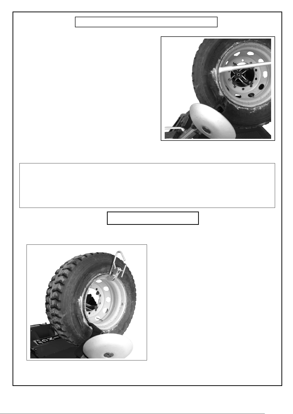
There are several methods of separating the tire from the rim;
1)- Inner heel, after leaving the wheel to the
active counter outside enabled.
Simultaneous turning of the tire, with roller
and the tire is further squeezed.
Remove both heels slowly outwards from the
rim (Fig.16).
When roller the tire, outward force applied, and when the heel sits on the inner cheek
of the rim and when the rotation of the tire on the rim prevents the clamp attached to
the rim and continue working.
Fig.15
Fig.16
CLAUSE 9
Page 10
12
Fort he front bead, recommended method is applying with roller.
Inner heel and foot wear reduction system described above generally apply to tractor tires.
After seperating the outer bead of tire from rim, tire gets out from the rim, with the help of moving part.
OPERATION AND USE
2)- After separating the inner and outer heel
from the edge, the foot arrangement is first
coated on the outer heel.
Lever mounted in the top of the foot, and the
tire, so that it can be pushed outwards.
Tires rotated clockwise, and slowly outward leg
assembly is towed
(Figure 17).
This process is continued until the heel totally
separated from the outer rim.
The same procedure is applied in the inner
heel, and completely separated from the tire rim
is provided.
(MOUNTAGE )
The tire is fitted on the rim facing the clamp. Inner
and outer heel of mature oiling or soaping
beautiful.
Removal - insert foot is placed between the rim
and the heel. The installation process is
performed by the turn of the tire clockwise.
When beads fit to the rim completely, assembly
finishes.
Do not inflate mature while it is on the machine,
after installation of the machine should be
removed from the tire, and pump elsewhere.
Wheel is connected to the mirror. on the upper part of the rim, pliers (clamp) mount (Fig.18)
For heavy tires, the process of connecting to the machine should be performed by two people.
Fig.17
Fig.18
Page 11

13
Before operating the machine,
lubricate the area shown in the
figure.
OILING PERIODS
ACCESSORIES PROVIDED
BEAD LIFTING LEVER (Fig.20)
A toll necessary for lifting the tyre bead onto the head
dunng demounting.
RIM PINCERS (Fig.21)
These are used when mounting tubeless and
supersingle tyres.
Fig.22
Fig.20
Fig.21
Points to be considered, by Setting the machine, or servicing;
1)Be sure that machine is not working.
2)Wear protection glasses and gloves.
3)After lubrication, do not squeeze your hand on moving parts of machine.
Fig.19
CLAUSE 10
Reductor gear montly
lubricated
Montly lubricated
Weeekly lubricated
Detachable cleaning
weeekly
in arm after the thin with
grease
lubricated
Cleaned on a weekly basis
After the thin with grease
lubricated
Page 12

14
ROUTINE MAINTENANCE
DAILY
1) CHECK THE CABLE OF THE MACHINE BEFORE THE RUNNING.
2) CHECK THE MACHINE IF THE MACHINE IS CLEAN AND MAINTENANCE IS COMPLETED.
3) CHECK THE HYDRAULIC CYLINDER AGAINST THE AIR LEAKAGE.
WEEKLY
1) CHECK IF THE DAILY MAINTENANCE IS DONE SYSTEMATICALLY.
2) CHECK IF THERE IS ANY OIL LEAKAGE ON THE CYLINDEROF THE BEAD LIFTING.
3) CHECK IF THERE IS ANY PROBLEM ON THE SWITCHES AND CONNECTION OF THE MACHINE.
MONTHLY
1) CHECK IF THE DAILY AND WEEKLY MAINTENANCES ARE DONE.
2) CHECK THE MACHINE PEDALS.
3) CHECK THE BELT OF THE MOTOR.
4) CHECK THE CONNECTION OF THE GEARBOX.
5) CHECK THE MOTOR CONNECTION BOLTS.
6 MONTHLY
1) CHECK THE DAILY, WEEKLY AND MONTHLY MAINTENANCE ARE DONE.
2) CHECK IF THERE IS ANY CONNECTION PROBLEMS ON THE CABLES AND SOCKET.
3) CHECK THE EARTH CONNECTION OF THE MACHINE ELECTRIC SYSTEM.
4) CHECK THE ADJUSTMENT OF THE DISMANTLING AND FIXING ARM.
YEARLY
1) CHECK THE DAILY, WEEKLY, MONTHLY AND 6 MONTHLY MAINTENANCE ARE DONE.
2) ARE THERE ANY UBNORMAL NOISES COMING FROM THE MACHINE.
3) ARE THERE ANY UBNORMAL NOISES COMING FROM THE ENGINE.
4) ARE THERE ANY UBNORMAL NOISES FROM THE MACHINE WHEN THE MACHINE IS NOT WORKING BUT
PLUGGED.
5) IS THERE ANY HEATING IN THE CABLES.
6) IS THERE ANY UBNORMALITYIN THE ENGINE DURING THE OPERATION.
IF ANY ANSWERS OF THESE GUESTIONS ARE YES CALL THE TECHNICAL SERVICE IMMEDIATELEY DO NOT
TRY TO SOLVE THE PROBLEMS BY YOURSELF.
CLAUSE 11
Page 13

15
THE MACHINE IS GURANTEED (1 YEARS) ;
FOR ANY MACHINE MAFUNCTIONS CONSULT THE SECTION “MALFUCTIONS: CAUSES AND POSSIBLE REMEDIES”
. ANY OTHER MALFUNCTIONS MUST BE CHECKED BY PROFESSIONALLY QUALIFIED PERSONNEL.
IN ALL CASES CONTACT THE ASSISTANCE SERVICE OF HATCO. FOR PROMPT ASSISTANCE IT IS IMPORTANT AT
THE TIME OF THE CALL TO SPECIFY THE MACHINE MODEL, THE PRODUCTION NO. (FOUND ON THE
REGISTRATION PLATE) AND TYPE OF MALFUNCTION.
hydraulic unit from the oil can that you can find in your accessories box provided with your
machine.
Only Use Shell Tellus 46 And Po Hd 46 Oıl At The System.
Yağ kapasitesi 12 litredir.
Our Guarantee Doesn’t Contaın Electrıc Motor
Control Cables Breaking And Cutting Damage That May Occur İs Outside The Guarantee.
Run The Machine İdle For 10 Minutes During The Winter Months. Start Work Later Please.
TO ORDER SPARE PARTS:
INDICATE THE SERIAL NUMBER OF THE MACHINE AND THE YEAR BUILT.
INDICATE THE CODE OF THE PIECE REQUESTED.
INDICATE THE QUANTITIY REQUIRED.
WARNINGS
USE ONLY ORIGINAL PARTS OF THIS MACHINE
THE MANUFACTURER TAKES NO RESPONSIBILITY OF THE NONORIGINAL
PARTS
THERE IS NO OIL IN THE HYDRAULIC UNIT
WARNING
ANY WORK ON THE ELECTRICAL, HYDRAULIC AND PNEUMATIC SYSTEMS
MUST BE CARRIED OUT ONLY BY PROFESSIONALLY QUALIFIED
PERSONNEL.
CLAUSE 12
Page 14

16
CONTROL BUTON CIRCUIT PLAN ( 3 PHASES )
CONTROL ARM
Up
Mirror Open
Down
MOVEMENT MOTOR
3A 3A
Left
EMERGENCY STOP
Right
HYDRAULIC MOTOR
18
17
MP
18
17
MP
3A
CLAUSE 13
Page 15

17
DEMONTAGE PLAN
CLAUSE 14
Page 16

18
Page 17

19
Page 18

20
CODE NO
DESCRİPTİON
1
83 01 000-EKO
Lower Body Group
2
83 03 000
Reductor Group
3
83 03 001
Reductor Body
4
83 03 013
Reductor Connectıon Group
5
01 0275 18-B14
Engine
6
01 0029 21
Reductor
7
83 03 005
Chaın Bottom Protectıon
8
01 0145 04
Reductor Large Gear
9
83 03 006
Internal Protectıon Plate Chaın
10
83 03 007
Reductor Abs Cover
11
83 03 008
Chaın Protectıon Abs Cover
12
01 0130 035-045-1
Washer
13
01 0074 010
Screw
14
01 0111 008
Washer
15
01 0062 035
Screw
16
01 0063 035
Screw
17
01 0063 025
Screw
18
01 0072 010
Screw
19
01 0112 06
Washer
20
01 0112 08
Washer
21
01 0115 008-04
Nut
22
01 0117 008
Fiber Nut
23
01 0123 050
Setscrew
24
01 0052 50
Fid
25
83 03 009
Connectıon Washer
26
01 0156 19
Two Rows Of Gear Chaın Pulley
27
01 0156 20
Double Roller Chaın Attachment
28
01 0145 05-35
Reductor Small Gear
29
83 03 012
Bearing Bracelet
30
83 03 011
Bearing Bracelet
31
01 0053 6207-FAG
Bearing
32
01 0140 072
Shaft Ring
33
83 03 010
Connectıon Washer
34
01 0084 035
Screw
35
01 0115 008
Nut
36
01 0062 080
Screw
37
83 07 000
Pıston Head Lıftıng Group
38
83 07 001
Cylınder Group
39
83 07 002
Pıston Group
40
53 03 003
Pıston Head
41
01 0117 020
Fiber Nut
42
01 0022 060-044
Compact Set
43
53 03 004
Pıston Nut
44
01 0023 030
Dust Seal
45
01 0021 30-38-6.5
Nutring
46
01 0024 030-3
O-Ring
47
01 0024 055-3
O-Ring
48
01 0024 059-3
O-Ring
49
01 0136 006
Fıttıng
50
01 0024 020-3
O-Ring
51
01 0027 009
Bearıng Bush
52
83 06 000
Slıde Cylınder Group
53
83 06 001
Cylınder Group
54
83 06 002
Pıston Shaft
55
01 0024 060-3
O-Ring
56
83 04 000
Mırror Group
57
83 04 001
Cylınder Body Group
58
01 0021 040-50-10
Nutring
59
01 0024 040-3
O-Ring
60
01 0023 40
Dust Seal
61
53 06 003
Mırror Body
62
53 06 017
Fıxıng Pın
63
53 06 007
Squeezıng Setscrew
64
01 0063 050-10.9
Screw
65
01 0112 10
Washer
66
53 06 010
Spın Rıght Lama
67
53 06 011
Spın Left Lama
SPARE PARTS LIST FOR RGU300.ECO TYPE
CLAUSE 15
Page 19

21
68
01 0130 014-020-1
Washer
69
01 0065 080 10.9
Screw
70
01 0117 014
Fiber Nut
71
53 06 012
Pullıng Lama
72
01 0072 016
Screw”
73
53 06 015
Spın Foot Connectıon Pın
74
01 0139 014
Shaft Rıng
75
53 06 014
Pullıng Lama Pın Connectıon
76
53 06 016
Squeezıng Foot
77
53 06 019
Short Wheel Squeezıng Teeth
78
53 06 020
Long Wheel Squeezıng Teeth
79
01 0111 012
Washer
80
53 06 013
Spıder
81
53 06 008
Remote Control Metal Root
82
53 06 006
Maın Shaft
83
01 0024 020-2.5
O-Ring
84
53 06 004
Rubber Head
85
01 0118 1-14 DİŞ
Nut
86
01 0022 100-075
Compact Set
87
53 06 005
Bracelet
88
83 04 003
Washer
89
53 06 021
Cylınder Cover
90
01 0112 05
Washer
91
01 0060 016
Screw
92
01 0024 007-2
O-Ring
93
01 0024 090-5
O-Ring
94
01 0073 025
Screw
95
01 0111 008
Washer
96
53 06 018
Holdıng Teeth Ofalumınum Wheels
97
01 0074 045
Screw
98
01 0064 040
Screw
99
01 0052 105
Fid
100
01 0159 01
Lockıng Valve
101
01 0150 315-ARKA
Glycerıne Manometer
102
83 11 000
Hydraulıc Unıt Group
103
83 11 001
Oıl Tank Group
104
53 08 001
Upper Cover Group
105
01 0034 21
Tank Top Seal
106
01 0034 01
Motor Seal
107
01 0145 35
Pump
108
01 0147 01
Brake Drum
109
01 0273 09-B5
Engine
110
01 0269 02
Flange
111
53 08 007
Couplıng Group
112
01 0014 21
Record
113
53 08 004
Fılter By-Pass Record
114
53 08 003
Pump Fılter Connectıon Pıpe
115
53 08 005
Pump Outlet Pıpe
116
53 08 006
Tank Return Pıpe
117
01 0149 25
Suctıon Fılter
118
01 0155 01
Tank Cover
119
01 0137 1-2 AL
Level Indıcator
120
01 0135 1-4
Dead End
121
01 0112 10
Washer
122
01 0072 035
Screw
123
01 0117 006
Fiber Nut
124
01 0074 035
Screw
125
01 0060 016
Screw
126
01 0072 020
Screw
127
01 0131 3-8
Copper Washer
128
01 0123 010
Setscrew
129
01 0014 20
Body Fıttıng
130
01 0014 23C
Pıpe Clamp Nut
131
53 09 000
Oıl Support Group
132
01 0072 055
Screw
133
53 00 005
Valve Cover Connectıon Pıpe
134
01 0039 08
Protect Valve Cover
135
53 09 000
Oıl Support Group
136
53 09 001
Body Group
Page 20

22
137
01 0014 176
Body Fıttıng
138
01 0131 1-4
Copper Washer
139
01 0156 02
Valve
140
01 0024 014-3
O-Ring
141
53 09 007
Pressure Regulating Valve Group
142
53 09 002
Pressure Adjustment Screw
143
01 0115 010
Nut
144
01 0024 017-2.5
O-Ring
145
53 09 005
Bottom Transıtıon
146
01 0024 009-2
O-Ring
147
53 09 006
Pressure Adjustment Spındle
148
53 09 004
Sprıng Bottom Had
149
01 0031 04
Pressure Adjustment Sprıng
150
53 09 003
Sprıng Top Had
151
01 0124 030
Setscrew
152
01 0115 010-KS
Nut
153
01 0039 08
Protect Valve Cover
154
83 02 000
Sledge Group
155
83 02 001
Body Group
156
83 02 003
Slıde Changıng Arm Apparatus Shaft Connectıon
157
01 0063 030
Screw
158
01 0063 040
Screw
159
75 02 003
Pressure Washer
160
01 0124 040-D
Setscrew
161
01 0115 010
Nut
162
01 0130 040-50-1
Washer
163
53 01 013
Shaft Washer Connectıon
164
01 0064 030
Screw
165
01 0063 035
Screw
166
33 06 002
Mıle Rubber
167
33 06 003
Slıde Rubber Powder - Prıntıng Plate
168
01 0063 025
Screw
169
83 02 004
Protectıon Cover - Large
170
83 02 005
Protectıon Cover - Small
171
83 02 002
Flat Bed Raıls Of Yellow
172
83 10 000
Accessorıes And Panel Connectıon Group
173
53 17 002
Cabınet Panel Operatıon
174
53 17 003
Panel Inner Metal
175
01 0202 03
Transformer
176
01 0028 64
Raıl Termınal
177
01 0028 27
Dıode Brıdge
178
01 0028 42
Cable Road
179
01 0196 10
Contactor
180
01 0028 28
Grounded Connector
181
01 0028 29
Connector
182
01 0028 30
Fuse Connector
183
01 0028 26
Connector Stopper
184
01 0200 02
Transformer
185
01 0198 16
Plastıc Cable Sleeve
186
01 0198 21
Plastıc Cable Sleeve
187
83 05 000
Removal Installatıon Arm Clamp Group
188
83 05 001
Removal Installatıon Arm Body Group
189
83 05 002
Removal Installatıon Key Group
190
83 05 004
Pressure Pıston
191
53 05 003
Wedge
192
53 05 006
Sprıng Fıxıng Washer
193
01 0112 16
Washer
194
01 0117 016
Fiber Nut
195
01 0066 120
Screw
196
01 0140 034
Hole Rıng
197
01 0139 020
Shaft Rıng
198
01 0031 115
Handle Removal Installatıon Tool Compressıon Sprıngs
199
01 0031 21
Iron Prınt Sprıng
200
01 0053 06004-MOS
Bearıng
201
53 14 000
Removal Installatıon Arm Group
202
53 14 001
Body Group
203
33 17 002
Roller Group
204
33 17 004
Belly Shaft
205
33 17 005
Connecting Shaft
Page 21

23
206
01 0031 52
Changıng Screw Pullıng Sprıng
207
33 17 006
Sprıng Connectıon Plate
208
53 14 003
Washer
209
53 14 002
Changıng Screw
210
01 0115 014
Nut
211
33 17 007
Set Dıstance Screw
212
33 17 003
Changıng Screw
213
53 13 000
Roller Shaft Connectıon Group
214
83 02 000-EKO
Tyre Trolley
215
83 00 001-EKO
Ramp Group
216
01 0073 060
Screw
217
01 0112 08
Washer
218
01 0117 008
Fiber Nut
219
53 21 002
Ramp Wheel
220
53 11 000
Control Group
221
53 11 001
Command Setup
222
53 11 002
Cover Mounting
223
53 11 003
Command Control Group
224
11 12 010A
Plastıc Pedal
225
01 0048 01
Hand Handle
226
01 0060 016
Bolt Screw
227
01 0115 005
Nut Screw
228
01 0071 016
Imbus Bolt Screw
229
01 0122 006
Set Screw
230
01 0107 040
Bolt Wıth Star Head
231
01 0134 02A
Plastic Cable Clamp
232
01 0195 04
Cable End
233
01 0134 02C
Connection Sheet
234
01 0072 020
Imbus Bolt Screw
235
01 0198 15
Plastıc Record
236
53 18 000
Group To Press
237
53 00 004
Lever
 Loading...