

Page 1
®
FASCUT
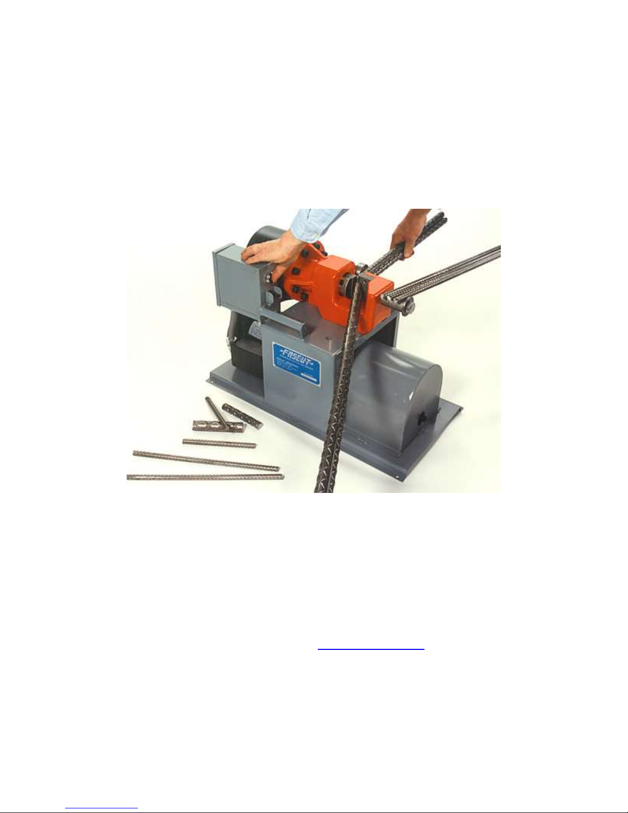
Model FC-800 Rebar Cutter
INSTRUCTION MANUAL
Built in the U.S.A. – Since 1979
FASCUT® Industries, 7248 Inama Rd., Sauk City, WI 53583
Phone: (608) 643-6678
Fax: (608) 643-2682
Website: www.fascut.com
Page 2

2
INTRODUCTION
FASCUT® incorporates a rugged alloy cast cutting head with a hydraulic cylinder and two
stage hydraulic pump. By following the enclosed instructions and maintenance schedule,
your FASCUT® machine will provide you with years of trouble free service.
WARNING: DO NOT attempt to operate until you have read thoroughly and understand
completely all instructions, rules, etc., contained in this manual. Failure to comply can and
may result in accidents involving fire, electric shock, or serious personal injury. Maintain this
instruction manual and review it frequently for continuing safe operation and instructing new
or possible third-party users.
DO NOT: TURN ON MACHINE BEFORE REMOVING THE SHIPPING PLUG ON THE TOP
OF THE OIL RESOVOIR AND REPLACING IT WITH THE SUPPLIED BREATHER CAP.
FAILURE TO DO THIS WILL RESULT IN DAMAGE TO THE MACHINE!
ALWAYS: wear safety glasses when operating. ALWAYS: keep fingers away from cutting
blades.
Model FC-800 Portable Cutter -- Specifications
Shear Capacity 1 bar - #8 (1”) 25mm, #7 (7/8”) 22mm, or #6 (3/4”) 19mm
Grade 60 (420 MPa) 2 bars - #5 (5/8”) 16mm
3 bars - #4 (1/2”) 13mm
4 bars - #3 (3/8”) 10mm
Shear Method Open Jaw Shear
Shear Time Approx. 2 to 4 seconds
Dimensions 26” x 13” x 19”
(L x W x H) 66cm x 33cm x 48cm
Weight 190 pounds / 86kg; built in carrying handles
Power Supply Two stage hydraulic pump driven by a one (1) hp. continuous duty
electric motor
Voltage / Amps 110-120 volts @ 15 amps – 50/60 Hz, single phase
220-240 volts @ 7.5 amps – 50/60 Hz, single phase
Page 3

3
NORMAL OPERATION
1. ALWAYS WEAR SAFETY GLASSES when operating.
2. ALWAYS KEEP FINGERS AWAY from cutting blades.
3. PLUG UNIT INTO a 110-120Volt outlet on a circuit with no less than a 20 amp
breaker. When using an extension cord, never use less than 12-guage wire.
Excessive voltage drop at the unit will cause the motor to burn out.
Or if 220 Volt
WIRE UNIT TO a 220-240 Volt, 50/60 cycle, 1 phase power source. Unit will draw
approximately 8 amps. When using an extension cord, never use less than 14guage wire. Excessive voltage drop at the unit will cause the motor to burn out.
4. GENERATOR MUST BE 5000 WATTS OR LARGER. Disable idle down feature
so generator engine is running at operating speed when turning on rebar cutter.
5. TURN ON using the toggle switch. In cold weather operations (below 32 deg. F),
turn unit on and allow to warm up for 5 to 10 minutes before using.
6. ALWAYS TURN OFF unit when not in use. DO NOT allow unit to idle for long
periods of time.
7. KEEP IN UPRIGHT POSITION to prevent loss of hydraulic oil from the oil tank
breather cap.
8. TO CUT a bar or bars, position bar between cutting blades. Bar must rest on the
bottom of the cutter opening as shown on the diagram below. Adjust the support on
the right side so the bar is held at 90 degrees to the cutting blades. Press the
green button until cut is made and then release. DO NOT CUT VERY SHORT
PIECES (3” OR SHORTER) as they could fly out and cause personal injury to you
or someone located close to you.
9. USE TYPE 801 cutting blade when cutting a lot of #3 or #4 bar. Your cutting times
will be faster because the cutter takes less time to advance and make contact with
the bar. Replace the regular 800 type cutting blade for the type 801 cutting blade
in the STATIONARY POCKET.
Page 4

4
ROUTINE MAINTENANCE
1) DRAIN & REPLACE HYDRAULIC OIL at least once each year or 200 operating
hours, whichever comes first. Allow unit to run for five minutes before draining to
warm up the oil. Remove drain plug and drain oil. Remove breather cap and plug
hole with a ⅜” pipe plug. Tip unit on end and fill thru drain hole to within one (1)
inch of the top and replace plug. DO NOT OVERFILL. Use good quality hydraulic
oil with a rating of ISO-VG 46 for general year round use. Use heavier ISO VG-68
for continuous hot weather operation. The unit will take approximately 6 quarts of
oil to refill. Set unit upright again and remove the ⅜” pipe plug and re-install the
breather cap, hand tightening only.
Failure to re-install the breather cap will result in damage to the machine.
2) GREASE through grease fitting on the left side of the cutter head before EACH use
period. Re-bar scale will quickly dry up grease. Removal of this scale, and
lubricating often will help to reduce wear.
Failure to remove excessive scale and lubricate machine regularly, will result
in increased wear and reduced life of the machine.
3) TIGHTEN blade securing hex bolts with the supplied Allen wrench before each use
period.
Failure to keep cutting blades securing hex bolts tight at all times could
result in injury to the operator and/or damage to the machine.
4) CUTTING BLADES have 4 indexable cutting edges. When one set of edges is
worn out, simply remove blade securing bolts and rotate to a new edge. If old edge
has mushroomed slightly, grind flat before installation to achieve proper “seating” of
the blade in its new position.
Do not attempt to re-sharpen worn edges. Resharpening changes the
dimension of the blades, causing them to not seat properly and damage the
blade holding socket.
5) CLEANING machine with a pressure washer routinely will help keep oil and grease
from building up and will extend the overall life of the machine.
Page 5
5
OPTIONS
REFERENCE FENCE ATTACHMENT
The reference fence attachment provides the operator with an adjustable material stop for
cutting uniform lengths. It can be set out to a maximum of approx. 4 feet.
ASSEMBLY
Bolt the fence bracket to the end of the steel bar using the bolt included with the bracket.
Next, slide the bar through the holder rings on the machine frame from the LEFT side.
Tighten the thumb screw on the holder after adjusting for desired length.
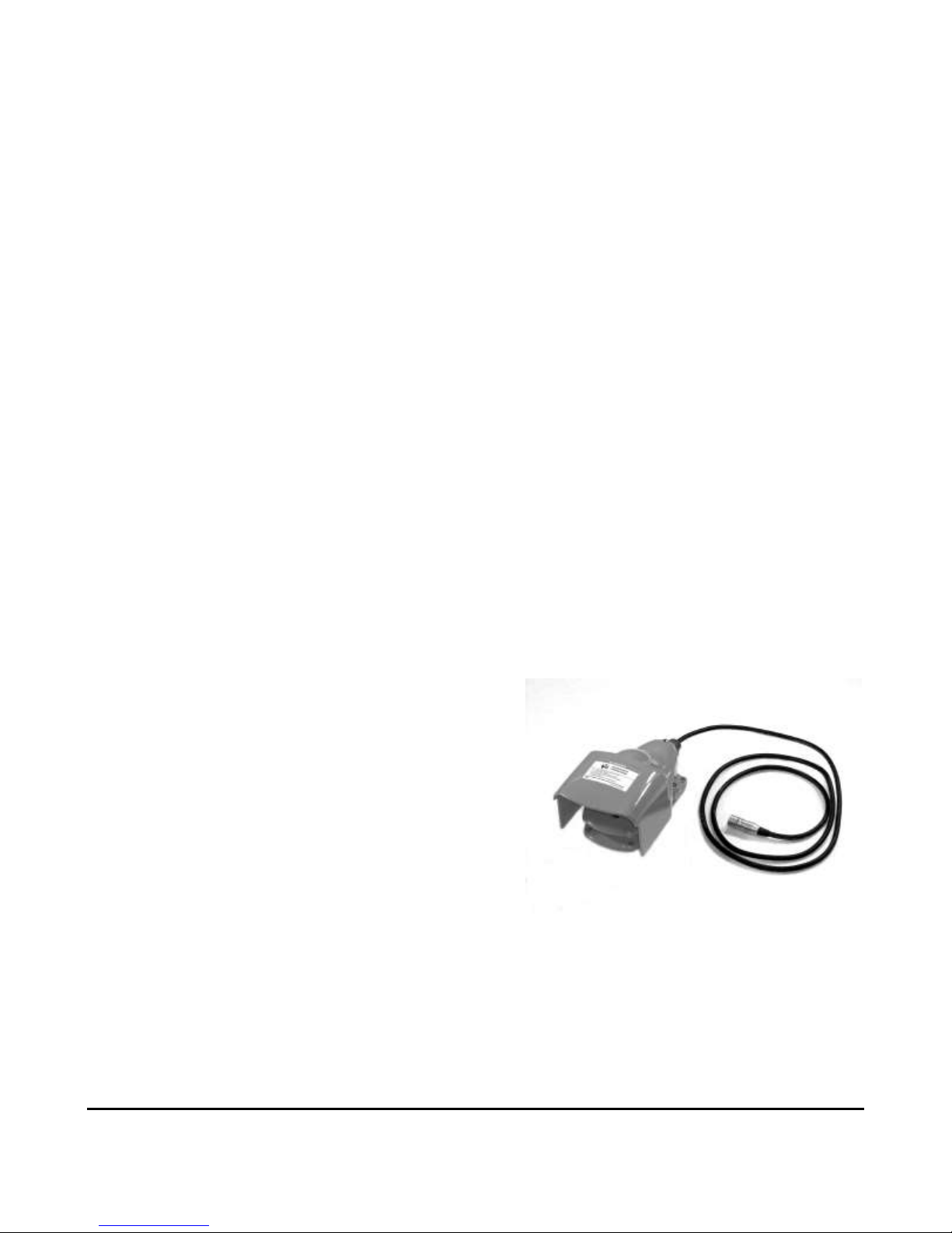
FOOT PEDAL CONTROL
The Foot Pedal comes fully assembled and prewired. It can be plugged in at any time.
A jack is provided on the underside of the electric
box. Push the plug into the jack until it locks in
place. To remove, just push the release button on
the jack.
When the foot pedal is plugged in, both the push
button on the machine and the foot pedal will
control the machine.
Note: Extra caution must be observed when using the foot pedal to
keep fingers away from cutting blades.
Never: Have one person work the foot pedal or push button while
another is feeding rebar into the machine.
Page 6
6
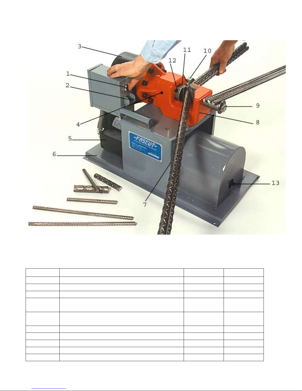
Index #
Description
Part #
Price/ea.
1
Push button control
76882
25.50
2
On/Off switch – 110-v
76619
8.12
2
On/Off switch – 220-v
76620
9.60
3
Hydraulic Cylinder (complete) – see next
page for breakdown.
12
Piston and rod assy. w/seal & loader –
see cylinder breakdown.
Hydraulic tube w/nut & ferrule, pressure
80465
10.50
Hydraulic tube w/nut & ferrule, return
80466
10.50
Hydraulic Cylinder elbow fitting (Fascut SAE)
73112
17.52
Hydraulic Power unit elbow fitting (Lenz)
73662
17.94
4
Grease fitting, straight
82547
1.24
FC-800 PARTS BREAKDOWN June 1, 2015
Page 7

7
5
Hydraulic Power unit (complete)
73405
1550.00
Electric Motor – serial #953 and up
75705
541.00
Electric Motor – serial #952 and down
75706
673.00
Motor Starting Capacitor
77253
18.07
Motor Fan
75734
41.95
Motor Fan Shroud
75721
47.50
Motor drive coupling
75715
12.75
Hydraulic Pump
73424
514.00
Oil tank
76406
89.00
Oil tank o-ring
76421
9.00
Breather Cap
71062
9.00
13
Oil drain plug
76245
.79
Valve (directional)
78919
94.35
Valve (kick-down)
78989
102.00
Valve coil – 110-v
78937
71.40
Valve coil – 24-v for 220-v unit
78938
77.50
6
Frame
80611
208.00
Electric box only, 110-v
66745
73.65
Electric box only, 220-v
66746
86.05
7
Allen wrench (1/4”)
80310
3.36
8
Cutter Head Casting
80700
748.00
Cylinder mount bolt & lock washer (8 req’d)
80705
1.20
Safety cover plate
80720
27.64
Safety Decal, cover plate
78643
.98
9
Bar support w/bolt & washer
80710
13.80
10
Bar support (adjustable)
80715
21.00
11
Cutting blade set w/bolts & lockwashers
FAS800
85.00
Cutting blade type 801 w/bolts & lw
FAS801
64.00
Foot Pedal Control
72365
129.00
Foot pedal cord w/plug
72369
18.79
Foot pedal socket
72373
23.66
Power cord w/plug (110-volts)
76745
12.28
Reference Fence Attachment
89725
75.00
Page 8
8
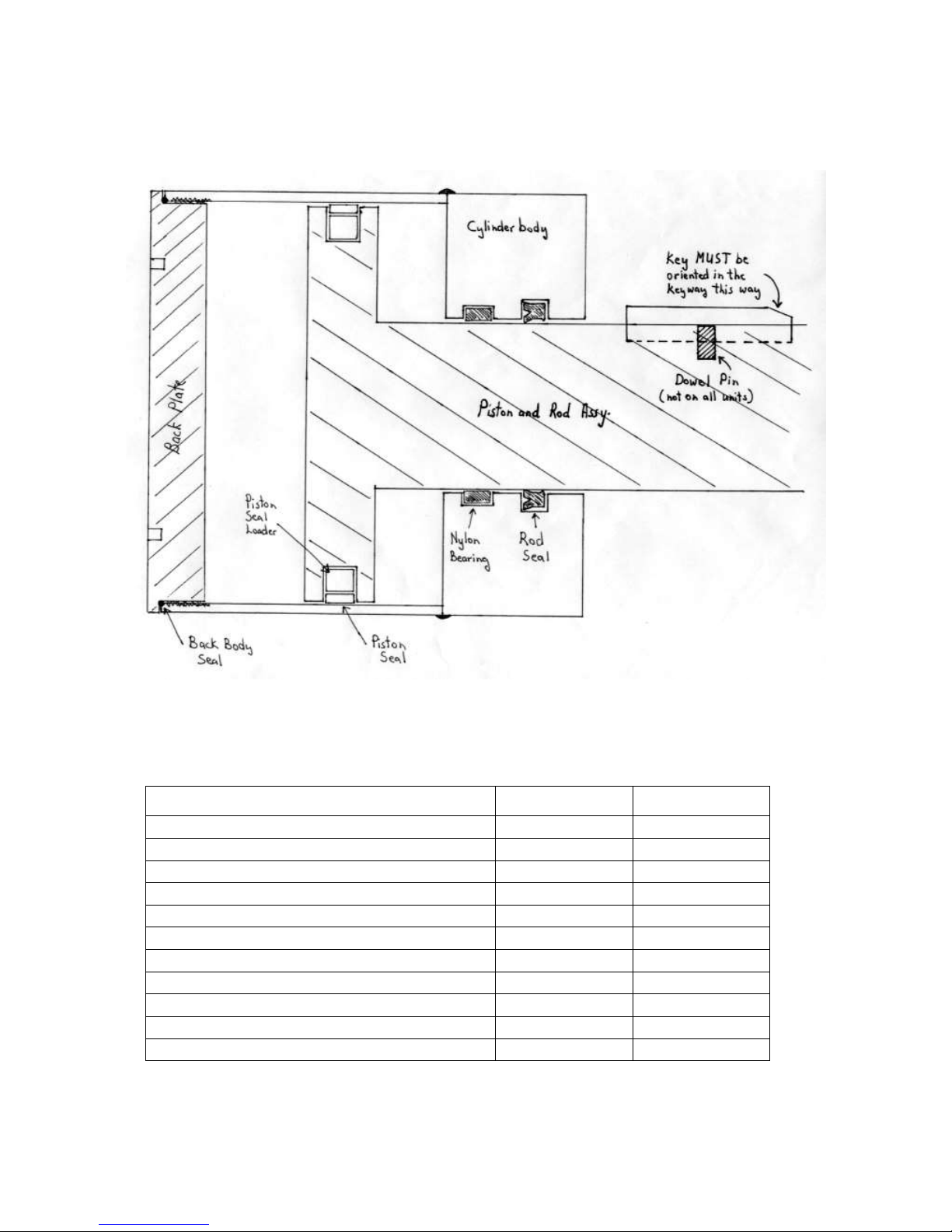
Description
Part #
Price/ea.
Hydraulic Cylinder (complete)
80430
711.00
Back body seal
80438
9.00
Piston Seal w/square loader ring
80436
34.90
Nylon Bearing
80440
4.95
Rod Seal
80442
15.50
Piston & rod assy. w/seal & loader
80434
310.00
Cylinder body w/back plate
80432
434.00
Key, ½” sq, #18380, #918 and up
80451
14.50
Key, ½” sq, #18379, #917 and down
80452
14.50
Spanner wrench, flat
80461
15.00
Spanner wrench, extended
80462
30.00
Cutter Hydraulic Cylinder
June 1, 2014
Page 9
9
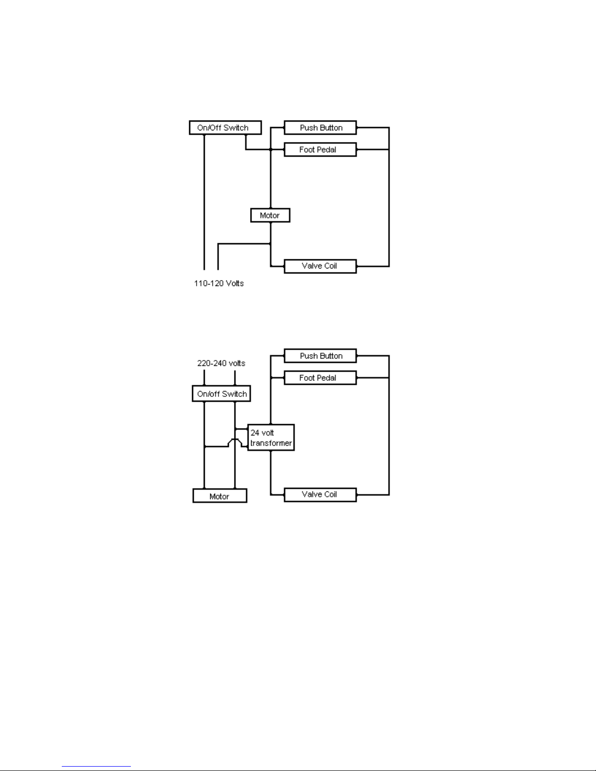
WIRING DIAGRAMS
The on/off switch turns power on to both the electric motor and the valve coil circuit. The
switch must be 1 HP rated.
Pressing the push button or foot switch completes the circuit to energize the valve coil which
makes the hydraulic cylinder extend out to make a cut.
Page 10

10
TROUBLESHOOTING FC-800 Rebar Cutter
TROUBLE
PROBABLE CAUSE
REMEDY
Motor will not
start
1. No power to unit.
2. Power cord or plug damaged.
3. On/off switch bad.
4. Motor wire connections loose.
1. Check supply cord, fuses,
or circuit breaker.
2. Replace power cord
w/plug.
3. Replace on/off switch.
4. Tighten motor wire
connections.
Motor hums,
then blows
circuit breaker,
or motor is
smoking
1. Extension cord too long or not
heavy enough.
2. Starting capacitor bad.
3. Starting switch bad.
4. Generator too small.
5. Generator running at idle
before starting unit.
6. Motor windings burnt out.
1. Extension cord must be
min. 12 gauge wire and no
longer than 100 feet.
2. Replace starting
capacitor.
3. Replace starting switch.
4. Use a 5 KW generator or
larger.
5. Turn off or disconnect idle
down feature.
6. Replace motor.
Motor runs, but
nothing happens
when push
button is
depressed.
1. Push Button is bad.
2. Loose wire.
3. Valve coil is bad.
4. Directional valve is bad.
1. Replace push button.
2. Check all wiring for loose
connections.
3. Replace valve coil.
4. Replace directional valve.
Foot Pedal does
not work. (push
button does)
1. Foot pedal cord or plug is
damaged.
2. Jack is bad.
3. Switch inside foot pedal is
bad.
1. Replace foot pedal cord
w/plug.
2. Replace jack.
3. Replace inside switch.
Cutting blade
bolts breaking
1. Cutting blade bolts are loose.
2. Cutting blades are dull.
3. Blade socket is deformed.
1. Retighten blade bolts
regularly.
2. Turn blades to new cutting
edge or replace blades.
3. Replace casting or piston
and rod assembly.
Page 11

11
Cutting blades
breaking
1. Blades are dull.
2. Blade bolts are loose.
3. Rebar is being dropped into
the cutter.
4. You are cutting “no grade”
steel
5. Bar is being cut on the top
corner of the cutting blade
1. Turn blades to a new
edge sooner.
2. Check blade bolts for
tightness more often.
3. Place rebar into the cutter
with greater care.
4. Only cut grade 40 or
grade 60 rebar.
5. Bar must rest on the
bottom of the cutter
opening.
Oil is leaking
1. Hydraulic tubes and fittings
are loose or damaged.
2. Hydraulic cylinder body seals
or rod seal is leaking
1. Check fittings for
tightness. Replace
damaged fittings or tube.
2. Install new body and/or
rod seals in hydraulic
cylinder.
Cutting is slow
and lacks power
1. Oil level is low.
2. Oil is contaminated.
3. Hydraulic pump is worn.
1. Add oil to tank.
2. Drain and refill oil tank
with fresh ISO-46
hydraulic oil.
3. Replace hydraulic pump.
Page 12

12
FASCUT® Industries, Inc.
LIMITED WARRANTY
This product has been thoroughly inspected and tested before leaving the factory. It is
guaranteed against defective workmanship and materials for a period of 1 year to the original
owner. Should any trouble develop, return defective part transportation prepaid to the factory.
If inspection shows trouble is caused by defective workmanship or material, all repairs will be
made without charge and returned, transportation prepaid. The guarantee does not apply
where: repairs or attempted repairs have been made by persons other than the factory;
repairs are due to normal wear; the tool has been abused or in an accident; misuse is evident
– caused by overloading the tool beyond its rated capacity; use on improper voltage or
current; use of the tool after partial failure or use with improper accessories.
This warranty is in lieu of all other warranties, expressed or implied, and there are no
warranties on merchantability or fitness for a particular purpose. In no event shall seller be
liable for incidental, consequential or special damages. This warrantee is void if
Warrantee/Registration card is not filled out and returned. This warranty gives you specific
legal rights, and you may also have other rights, which vary from state to state.
SERIAL NUMBER _________________________ DATE _______________________
FASCUT
Sauk City, WI 53583
Phone: (608) 643-6678
Fax: (608) 643-2682
Website: www.fascut.com
®
Industries, Inc.
7248 Inama Rd.
 Loading...