

Page 1

FARR 400UTV OWNER'S MANUAL
Page 2
Page 3

INTRODUCTION
Congratulations on your purchase of the 400UTV-EC. It represents the result of many years of
experience in the production of fine sporting, UTVs, and pacesetting racing machines. With the
purchase of this UTV, you can now appreciate the high degree of craftsmanship and reliability.
This manual will provide you with a good basic understanding of the features and operation of
this UTV. This manual includes important safety information. It provides information about special
techniques and skills necessary to ride your UTV. It also includes basic maintenance and inspection
procedures. If you have any questions regarding the operation or maintenance of your UTV, please
consult the dealer.
AN IMPORTANT SAFETY MESSAGE
● READ THIS MANUAL TOGETHER WITH TIPS FOR THE UTV RIDER CAREFULLY AND COMPLETELY
BEFORE OPERATING YOUR UTV. MAKE SURE YOU UNDERSTAND ALL INSTRUCTIONS.
● PAY CLOSE A TTENTION TO THE WARNING AND CAUTION LABELS ON THE UTV.
● NEVER OPERATE A UTV WITHOUT PROPER TRAINING OR INSTRUCTION.
● THIS UTV, AND ANY OTHER UTV OVER 90cc, SHOULD NOT BE RIDDEN BY ANYONE UNDER 16 YEARS
OF AGE.
Page 4
IMPORTANT MANUAL INFORMATION
FAILURE TO FOLLOW THE WARNINGS CONTAINED IN THIS MANUAL CAN RESULT IN SERIOUS
INJURY OR DEATH.
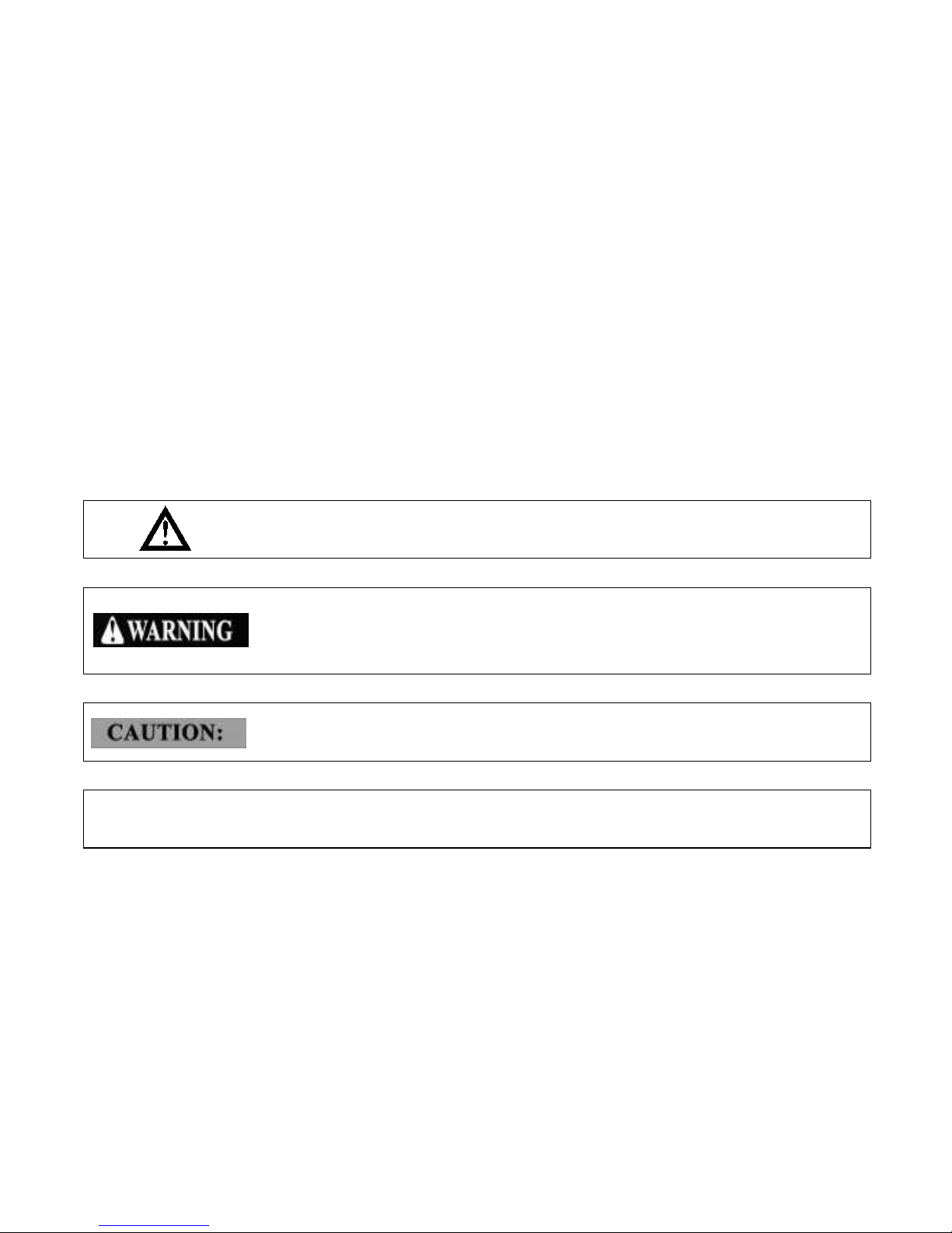
Particularly important information is distinguished in this manual by the following notations:
The Safety Alert Symbol means ATTENTION!
YOUR SAFETY IS INVOLVED!
Failure to follow WARNING instructions could result in severe injury or
death to the machine operator, a bystander or a person inspecting or
repairing the machine.
A CAUTION indicates special precautions that must be taken to avoid
damage to the machine.
A NOTE provides key information to make procedures easier or clearer.
NOTE:
Page 5

IMPORTANT NOTICE
Curve speed must be smaller than 30km/h.
This UTV has been passed the EC certificate, it can run on any public street, road, and highway.
Please check your local riding laws and regulations before operating this UTV.
When the temperature is below -20℃ (-4°F), please park the UTV in the place where the
temperature is higher than -20℃ (-4°F). After the UTV has warmed up, the UTV can be started.
Please see page 6-3 on the warming up process.
When the temperature is higher than 38℃ (100°F), and when you park the UTV after it run at high
speed, please keep engine running for 3 minutes at idle mode and make sure that the radiator fan
still work for 3 minutes to prevent cooling water from boiling. Then turn off the power switch to save
the battery.
Because in this UTV, its fuel tank setting position is lower than the carburetor, and it is supplied fuel
by negative pressure petrol pump, so for the consideration of safety, the factory will dispel all the
petrol in the carburetor, petrol pump and petrol pipe. When the customer has refueled the UTV and
start it for the first time, it will take longer time to start the UTV. The starting requirement is as follows:
each starting time is 5 seconds, then stop by 15 seconds and restart, you need to start your UTV
5-10 times.
Page 6

CONTENTS
1 LOCATION OF THE WARNING
2 AND SPECIFICATION LABELS……1-1
2. SAFETY INFORMATION………………2-1
3. DESCRIPTION AND VEHICLE
IDENTIFICATION………………………3-1
Identification Number Records…………3-3
Vehicle identification number and
Model label………………………………3-3
Verification sign of EC……………………3-4
4. CONTROL UNCTIONS………………4-1
Ignition Switch……………………………4-1
Combination Switch……………………4-2
Turning light switch………………………4-3
Emergency light button…………………4-3
Horn button………………………………4-3
Indicator and Warning Lights……………4-4
Multi-Function Display Gauge…………4-7
Odometer and Trip Meter Modes………4-7
Clock Mode………………………………4-8
Fuel gauge………………………………4-8
On-Command Four-Wheel–Drive
And Differential Gear Lock Switches…4-9
Accelerator Pedal………………………4-13
Brake Pedal……………………………4-14
Parking brake pedal……………………4-14
Drive Select Lever……………………4-15
Fuel Tank Cap…………………………4-16
Starter……………………………………4-16
Seats……………………………………4-16
Seat belts………………………………4-18
Glove Compartment……………………4-20
Cargo Bed………………………………4-20
Opening and Closing the Tailgate……4-20
Lifting and Lowering the Cargo Bed…4-21
Front and Rear Shock Adjustment
……4-23
1
Page 7

Trailer Hitch Bracket……………………4-25
Auxiliary DC Jack………………………4-25
5 PRE-OPERATION CHECKS…………5-1
Brakes……………………………………5-2
Front and Rear Brakes Brake Pedal…5-2
Brake Fluid Level………………………5-3
Brake Operation…………………………5-3
Fuel………………………………………5-4
Gasohol…………………………………5-5
Engine Oil………………………………5-6
Coolant……………………………………5-6
Final Gear Oil……………………………5-7
Differential Gear Oil……………………5-7
Throttle Pedal……………………………5-8
Throttle Free play………………………5-9
Throttle Free play Inspection……………5-9
Throttle Free play Adjustment…………5-9
Steering Wheel Inspection……………5-10
Seat Belts………………………………5-10
Fittings and Fasteners…………………5-10
Lights……………………………………5-10
Switches………………………………5-10
Tires……………………………………5-11
How To Measure Tire Pressure………5-13
Tire Wear Limit…………………………5-14
Tires for Public use……………………5-14
6. OPERATION………………………………6-1
Starting a cold engine……………………6-1
Starting a warm engine…………………6-3
Jump-starting……………………………6-3
Warming Up………………………………6-5
Drive Select Lever Operation And
Reverse Driving…………………………6-5
Parking……………………………………6-9
Parking On A Slope……………………6-10
Accessories and loading………………6-11
7 DRIVING YOUR VEHICLE……………7-1
Getting To Know Your Vehicle…………7-1
Learning To Operate Your Vehicle……7-5
Turning Your Vehicle……………………7-6
Operating Improperly in Reverse………7-7
Braking……………………………………7-8
Going Uphill………………………………7-8
Page 8

Going Downhill…………………………7-10
Crossing Through Shallow Water……7-11
Vehicle Immersion……………………7-13
Rear Axle Differential Lock …………7-14
Riding Over Rough Terrain……………7-15
Riding In Brush Or Wooded
Areas……………………………………7-16
Encountering Obstacles On The
Trail………………………………………7-17
8. PERIODIC MAINTENANCE AND
ADJUSTMENT…………………………8-1
Periodic Maintenance Chart For
The Emission Control System…………8-3
General Maintenance And
Lubrication Chart…………………………8-4
Hood………………………………………8-6
To Open…………………………………8-6
To Close…………………………………8-6
Engine Oil And Oil Filter Cartridge……8-7
To Check Engine Oil Level……………8-7
To Change the Engine Oil (With or With-out
Oil Filter Cartridge Replacement) ……8-8
Final Gear Oil
Checking the Final Gear Oil Level……8-11
Changing the Final Gear Oil…………8-12
Differential Gear Oil……………………8-13
Checking the Differential Gear Oil Level…8-13
Changing the Differential Gear Oil …8-14
Coolant…………………………………8-15
Checking the Coolant Level…………8-15
Changing the Coolant…………………8-16
Axle Boots………………………………8-17
Spark Plug Inspection…………………8-18
Removal…………………………………8-18
Inspection………………………………8-18
Installation………………………………8-19
Cleaning The engine Air Filter
Elements………………………………8-20
Cleaning The Spark Arrester…………8-24
Valve Clearance………………………8-25
Front Brake Pad Check………………8-26
Rear Brake Pad Check………………8-26
Checking The Brake Fluid Level……8-27
Brake Fluid Replacement……………8-28
Checking The Brake Pedal……………8-28
Page 9

Brake Light Switch Adjustment………8-30
Cable Inspection And Lubrication……8-31
Brake Pedal And Accelerator
Pedal Lubrication………………………8-32
Rear Knuckle Upper And Lower
Pivot Lubrication………………………8-32
Steering Shaft Lubrication……………8-33
Wheel Removal………………………8-34
Wheel Installation………………………8-34
Battery…………………………………8-35
Battery Maintenance…………………8-37
Fuse Replacement……………………8-37
Replacing A Headlight Bulb……………8-40
Tail/Brake Light Bulb
Replacement……………………………8-42
Check and solution to Common
Problems in Vehicle……………………8-44
CLEANING AND STORAGE…………9-1
A. Cleaning……………………………9-1
B. Storage………………………………9-3
SPECIFICATIONS……………………10-1
9
10
Page 10
1-1
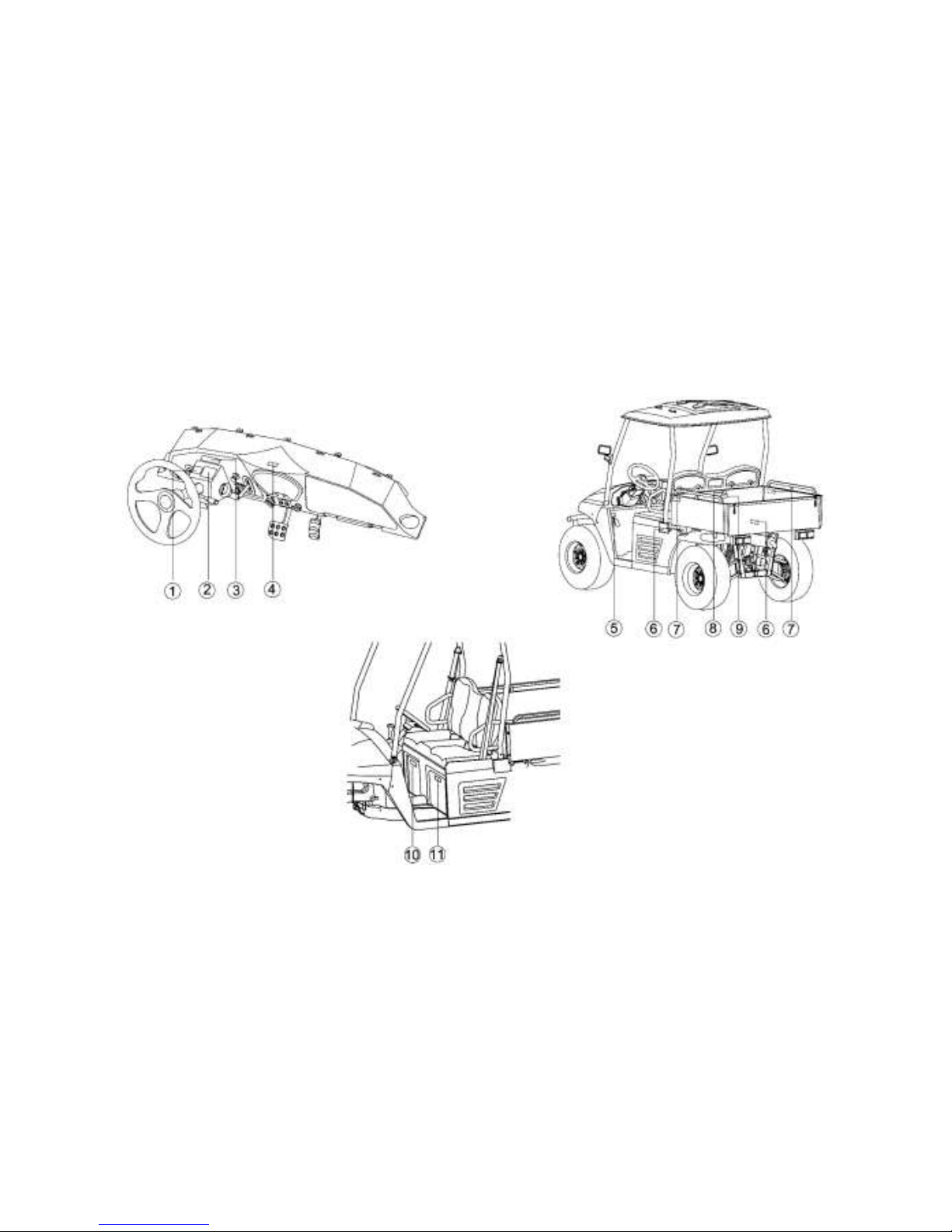
LOCATION OF THE WARNING AND SPECIFICATION LABELS
Page 11
1-2
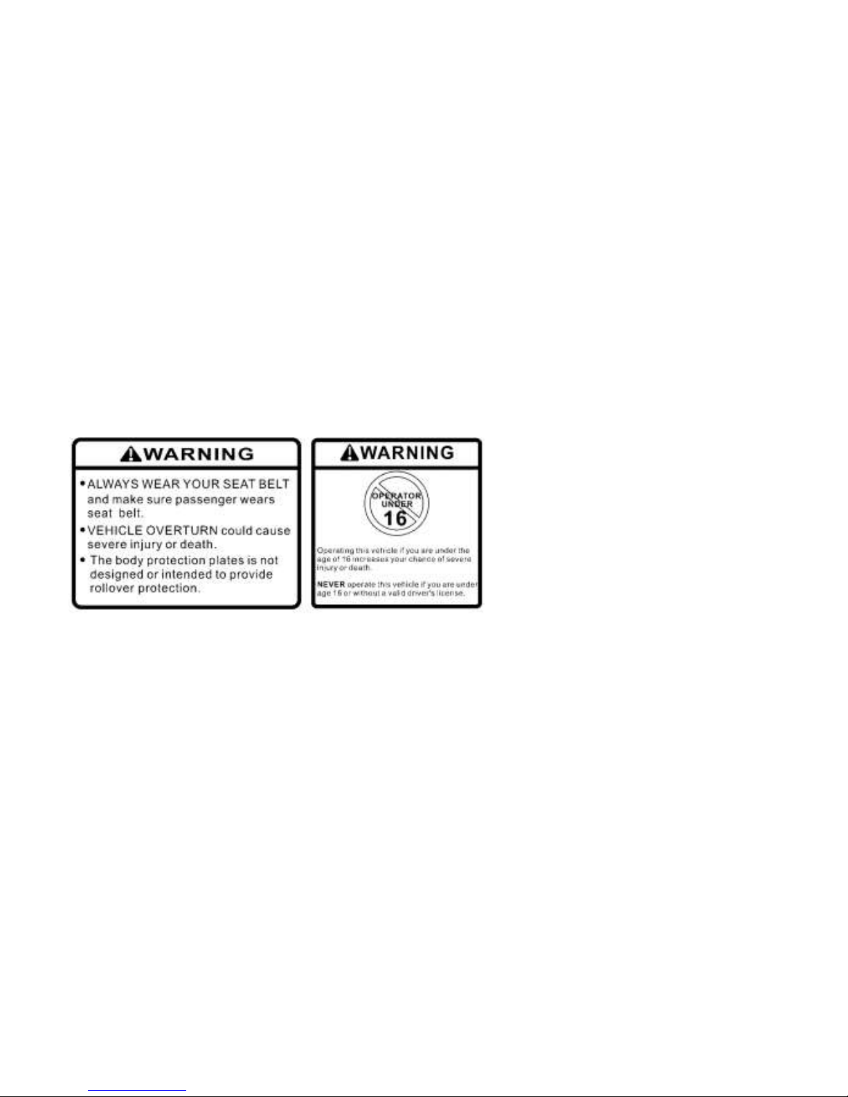
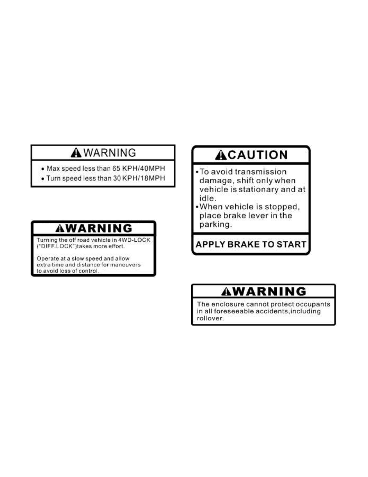
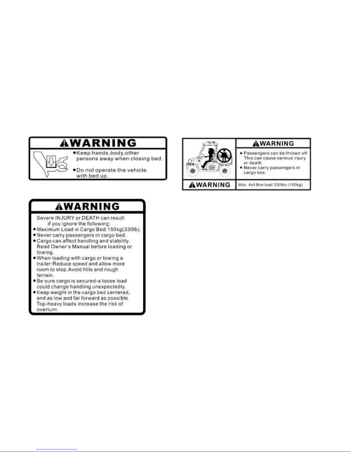
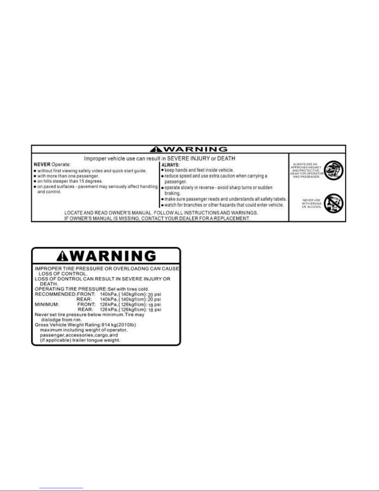
Read and understand all of the labels on your vehicle. They contain important information for
safe and proper operation of your vehicle.
Never remove any labels from your vehicle. If a label becomes difficult to read or comes off, a
replacement label is available from your dealer.
①
Page 12
1-3
②
③
④
⑤
Page 13
1-4
⑥
⑦
⑧
Page 14
1-5
⑨
⑩
Page 15
2-1
This utility vehicle handles differently from other vehicles including cars and UTVs.
SEVERE INJURY OR DEATH can result if you do not follow these instructions:
● Read this manual and all labels carefully and follow the operating procedures described.
● This vehicle is designed to carry the driver and three passengers.
NEVER CARRY PASSENGERS IN THE CARGO BED.
● Always be sure the driver and passengers are wearing seat belts.
● Never give a ride to a passenger who is too small to reach and hold the handgrip fixed before
the seat.
● Always avoid operating the vehicle on any paved surfaces, including sidewalks, driveways,
parking lots, and streets.
● Never operate this vehicle on any public street, road, or highway, even a dirt or gravel one.
● Never operate this vehicle without wearing an approve motorcycle helmet that fits properly. You
should also wear eye protection (goggle or a face shield), gloves, over-the-ankle boots,
long-sleeved shirt or jacket, and long pants.
● Never consume alcohol or drugs before or while operating this vehicle.
● Never operate at speeds too fast for your skills or the conditions. Always go at a speed that is
proper for the terrain, visibility, operating conditions, and your experience.
● Never attempt jumps of other stunts.
● Always inspect your vehicle each time you use it to be sure it is in safe operating condition,
SAFETY INFORMATION
Page 16

2-2
Always follow the inspection and maintenance procedures and schedules described in this
manual.
● Always keep both hands, arms, feet, and legs inside the vehicle at all times during operation.
Keep your feet on the floorboard. Never hold onto the enclosure. Otherwise, your hands could
be injured if it is caught between the enclosure and an obstacle outside the vehicle.
● Always keep both hands on the steering wheel when driving.
● Never wrap your thumbs and fingers around the steering wheel. This is particularly important
when driving in rough terrain. The front wheels will move right and left as they respond to the
terrain, and this movement will be felt in the steering wheel. A sudden jolt could wrench the
steering wheel around, and your thumbs or fingers could be injured if they are in the way of the
steering wheel spokes.
● Always go slowly and be extra careful when operating on unfamiliar terrain. Always be alert to
changing terrain conditions when driving the vehicle.
● Never operate on excessively rough, slippery, or loose terrain until you have learned and
practiced the skills necessary to control the vehicle on such terrain. Always be especially
cautious on these kinds of terrain.
● Never turn at excessive speed. Practice turning at slow speeds before attempting to turn at
faster speeds. Do not attempt turns on steep inclines.
● Never operate the vehicle on hills that are too steep for it or for your abilities. Go straight up and
down hills where possible. Maximum slope angle: 15°.
● Never operate on hills that are slippery or ones where you will not be able to see far enough
ahead of you. Never go over the top of a hill at speed if you cannot see what is on other side.
Page 17

2-3
● Always follow proper procedures for going uphill. If you lose control and cannot continue up a hill,
back down the hill with the engine in reverse gear. Use engine braking to help you go slowly. If
necessary, use the brakes gradually to help you go slowly.
● Always check terrain before going down hills. Go as slowly as possible. Never go down a hill at
high speed.
● Always check for obstacles before operating in a new area.
● Never operate the vehicle in fast flowing water or water deeper than the floorboards on this
model. Remember that wet brakes may have reduced stopping ability. Test your brakes after
leaving water. If necessary, apply the brake several times to let friction dry out the linings.
● Always be sure there are no obstacles or people behind you when you operate in reverse.
When it is safe to proceed in reverse, go slowly.
● Do not brake abruptly when carrying loads in the cargo bed.
● Always use the size and type of tires specified in this manual.
● Always maintain proper tire pressure as described in this manual.
● Never exceed the stated load capacity. Cargo should be as far forward in the bed as possible,
and distributed evenly from side to side. Be sure cargo is secured so that it cannot move around
during operation. Reduce speed and follow instructions in this manual for carrying cargo or
pulling a trailer. Allow greater distance for braking.
Page 18
2-4
WARNING
POTENTIAL HAZARD
Improper handling of gasoline.
WHAT CAN HAPPEN
Gasoline can catch fire and you could be burned.
HOW TO AVOID THE HAZARD
Always turn off the engine when refueling. Do not refuel right after the engine has been
running and is still very hot. Do not spill gasoline on the engine or exhaust pipe(or muffler)
when refueling. Never refuel while smoking, or while in the vicinity of sparks, open flames,
or other sources of ignition such as the pilot light of water heaters and clothes dryers.
When transporting the vehicle in another vehicle, be sure it is kept in an upright
position. Otherwise, fuel may leak out of the carburetor or fuel tank.
WHAT CAN HAPPEN
Gasoline is poisonous and can cause injuries.
HOW TO AVOID THE HAZARD
If you should swallow some gasoline or inhale a lot of gasoline vapor, or get some gasoline
in your eyes, see your doctor immediately. If gasoline spills on your skin, wash with soap
and water. If gasoline spills on your clothing, change your clothes.
Page 19
2-5
WARNING
POTENTIAL HAZARD
Starting or running the engine in a closed area.
WHAT CAN HAPPEN
Exhaust fumes are poisonous and may cause loss of consciousness and death within a
short time.
HOW TO AVOID THE HAZARD
Always operate your vehicle in an area with adequate ventilation.
Page 20
3-1
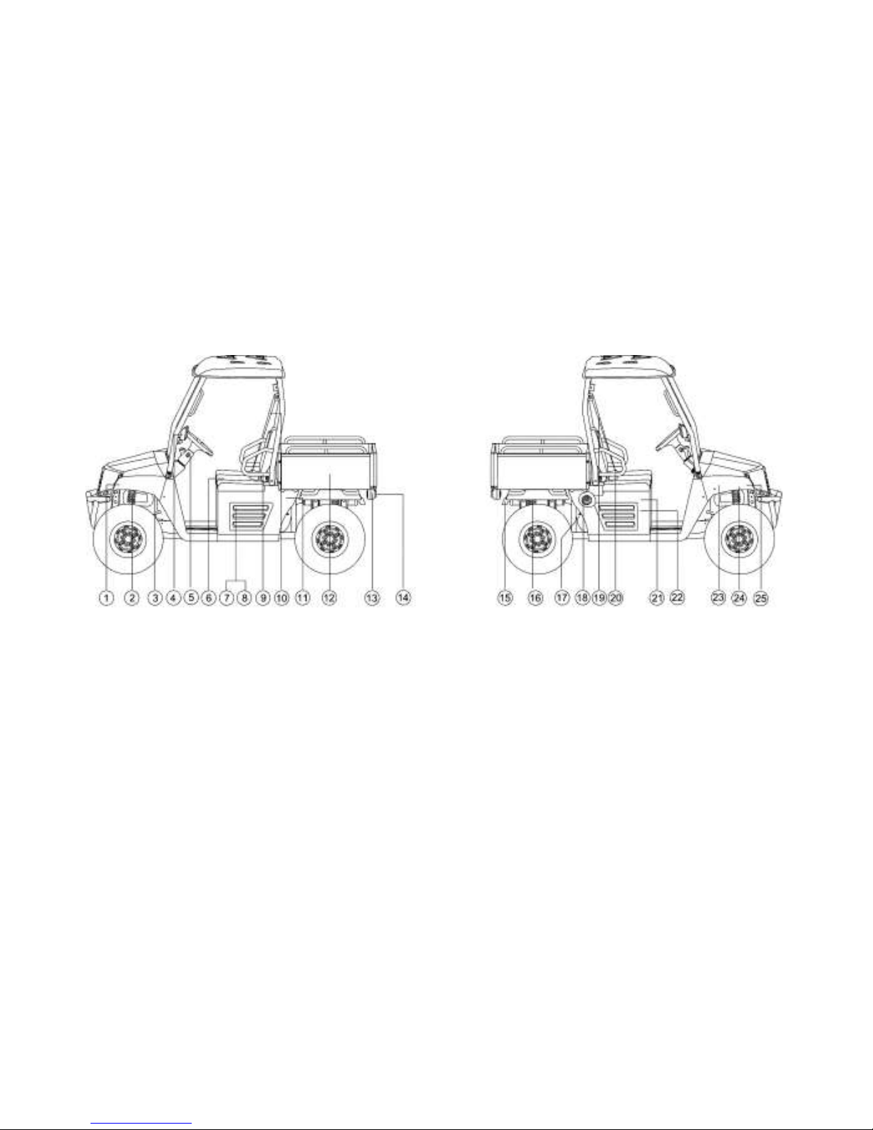
DESCRIPTION AND VEHICLE IDENTIFICATION
1. Headlights
2. Front shock absorber assembly
3. Brake fluid reservoir
4. Rear mirror
5. Ignition Switch Assembled
6. Driver seat
7. Battery
8. Fuses
9. Left body protection plate
10. Driver seat belt
11. Air filter element
12. Cargo bed
13. Tail/brake lights
14. Turning-light, Rear
15. Spark arrester
16. Rear shock absorber assembly
17. CVT-belt case
18. Fuel tank cap
19. Passenger seat belt
20. Right body protection plate
21. Spark plug
22. Oil filter cartridge
23. Radiator cap
24. Coolant reservoir
25. Turning-light, Front
Page 21
3-2
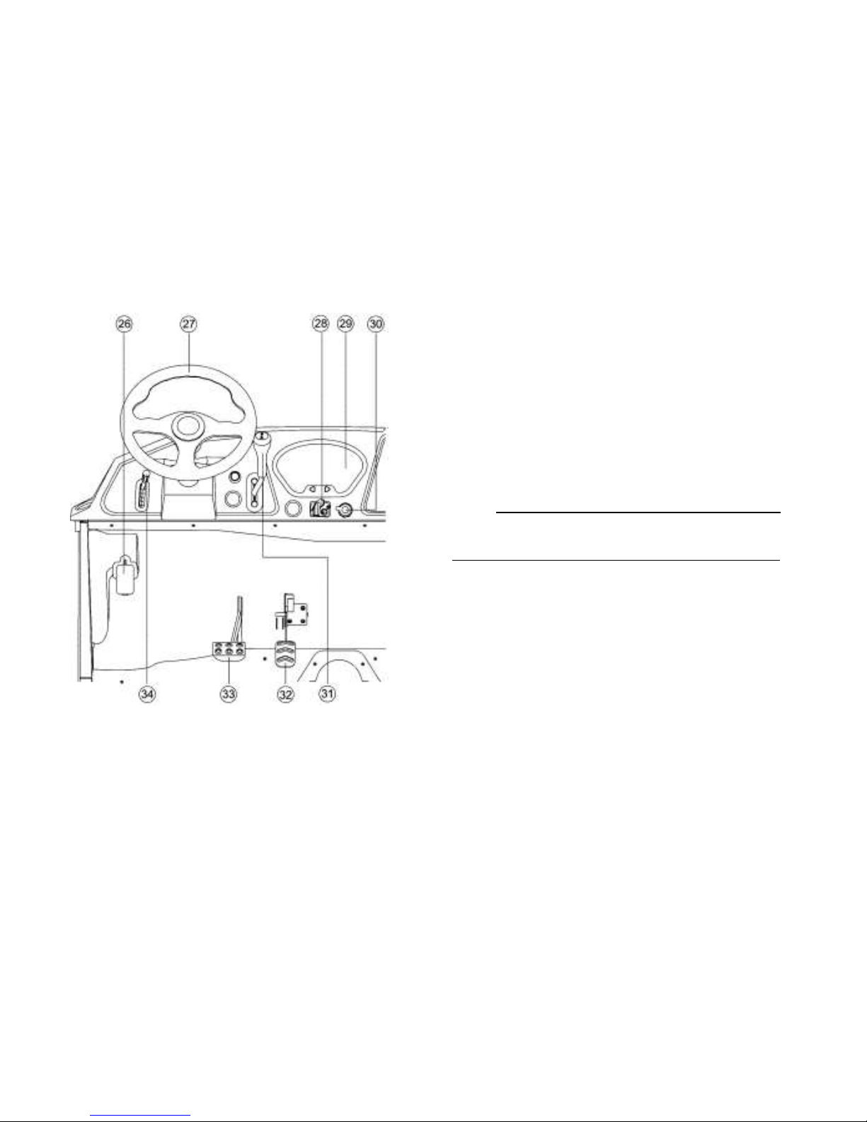
26. Parking brake lever
27. Steering wheel
28. Ignition switch
29. Multi-function display gauge
30. Auxiliary DC jack
31. Drive select lever
32. Accelerator pedal
33. Brake pedal
34. Release parking handle
NOTE:
The vehicle you have purchased may differ slightly from
those in the figures of this manual.
Page 22
3-3
Identification Number Records
Record the Vehicle Identification Number and
model label information in spaces provided for
assistance when ordering spare parts from a
dealer or for reference in case the vehicle is
stolen.
1. VEHICLE IDENTIFICATION NUMBER:
2. MODEL LABEL INFORMATION
○
●
Vehicle identification number and
Model label
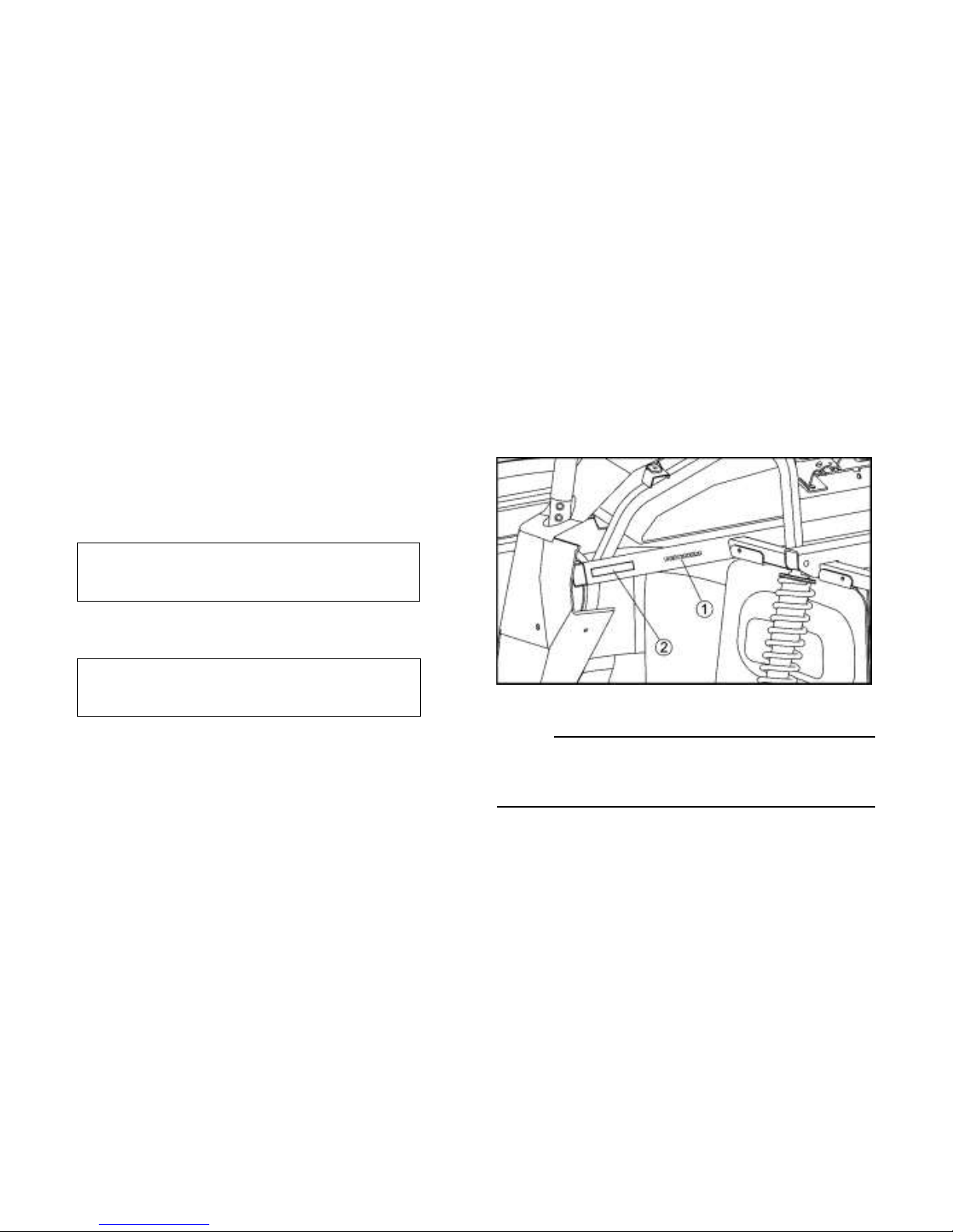
The Vehicle Identification Number is stamped
into the frame.
1. Vehicle identification number 2. Model label
NOTE:
The vehicle identification number is used to
identify your vehicle.
Page 23
3-4
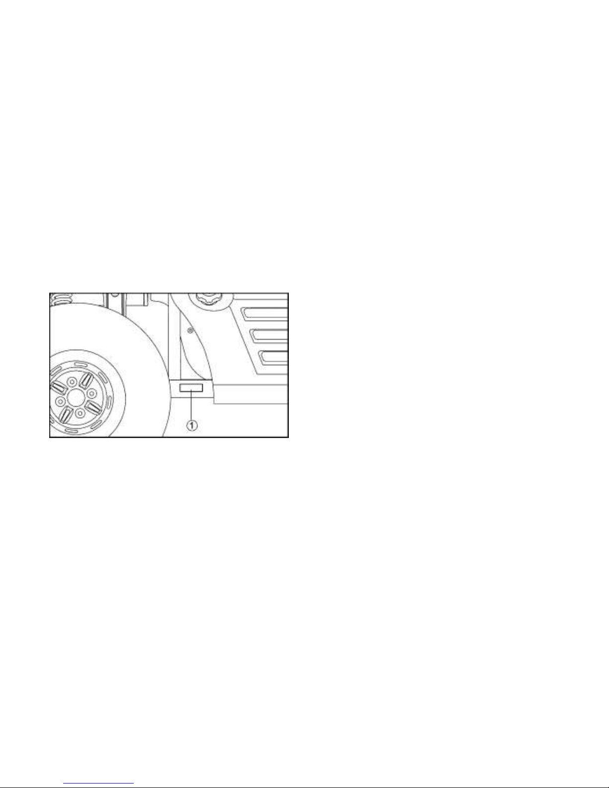
Verification sign of EC
Record the information on this label in the
space provided. This information will be needed
to order spare parts from your dealer.
1. Verification sign of EC
Page 24
4-1
CONTROL FUNCTIONS
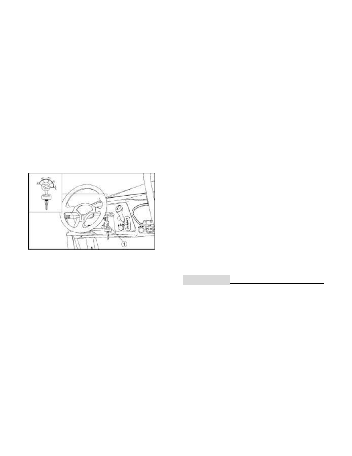
Ignition Switch
1. Ignition Switch
Functions of the respective switch positions
are as follows:
ON:
All electrical circuits are supplied with power,
and the headlights and taillights come on
when the light switch is on.
OFF:
All electrical circuits are switched off. The key
can be removed in this position.
START:
The electric starter is engaged by turning and
holding the key in this position. Release the
key when the engine starts.
KEY:
Turning the steering wheel can lock the
direction, while unplugging the key.
1CAUTION:
● Do not operate the electric starter
continuously for more than 5 seconds, or
starter damage could occur. Wait at
Page 25
4-2
least 5 seconds between each operation
of the electric starter to let it cool.
● Do not turn the key to the “START”
position with the engine running, or
damage to the electric starter can result.
● See starting instructions prior to starting
the engine. (See pages 6-1— 6-3 for
details.)
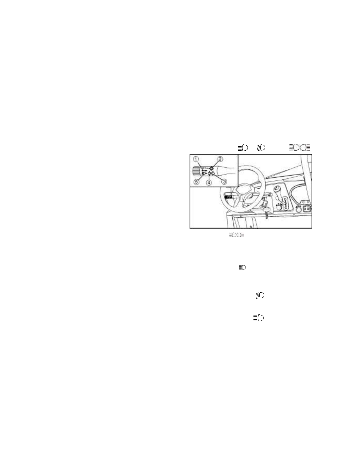
Combination switch
Light switch “ / / OFF/ ”
1. Position lamp
2. Headlight switch
3. Right-turn signal
4. Left-turn signal
5. High beam switch
6. Emergency light button
● Set the switch to “ ”, to turn on the low
beam.
● Set the switch to “ ”, to turn on the high
Page 26
4-3
beam.
● Set the switch to “OFF”, to turn off all the
lights.
● Set the switch to “ ” to turn on the
little lights in the headlights and the
taillights.
1CAUTION:
Do not use the headlights more than fifteen
minutes if the engine is turned off. Otherwise
the battery may discharge to the point that
the starter motor will not operate properly. If
this happens, remove the battery and
recharge it.
Turning light switch
Setting the switch, the turning light would
spark correspondently. The buzzer will sound.
Emergency light button
Press this button. The four turning lights will
spark continuously. At the same time, the
buzzer will sound.
Horn button
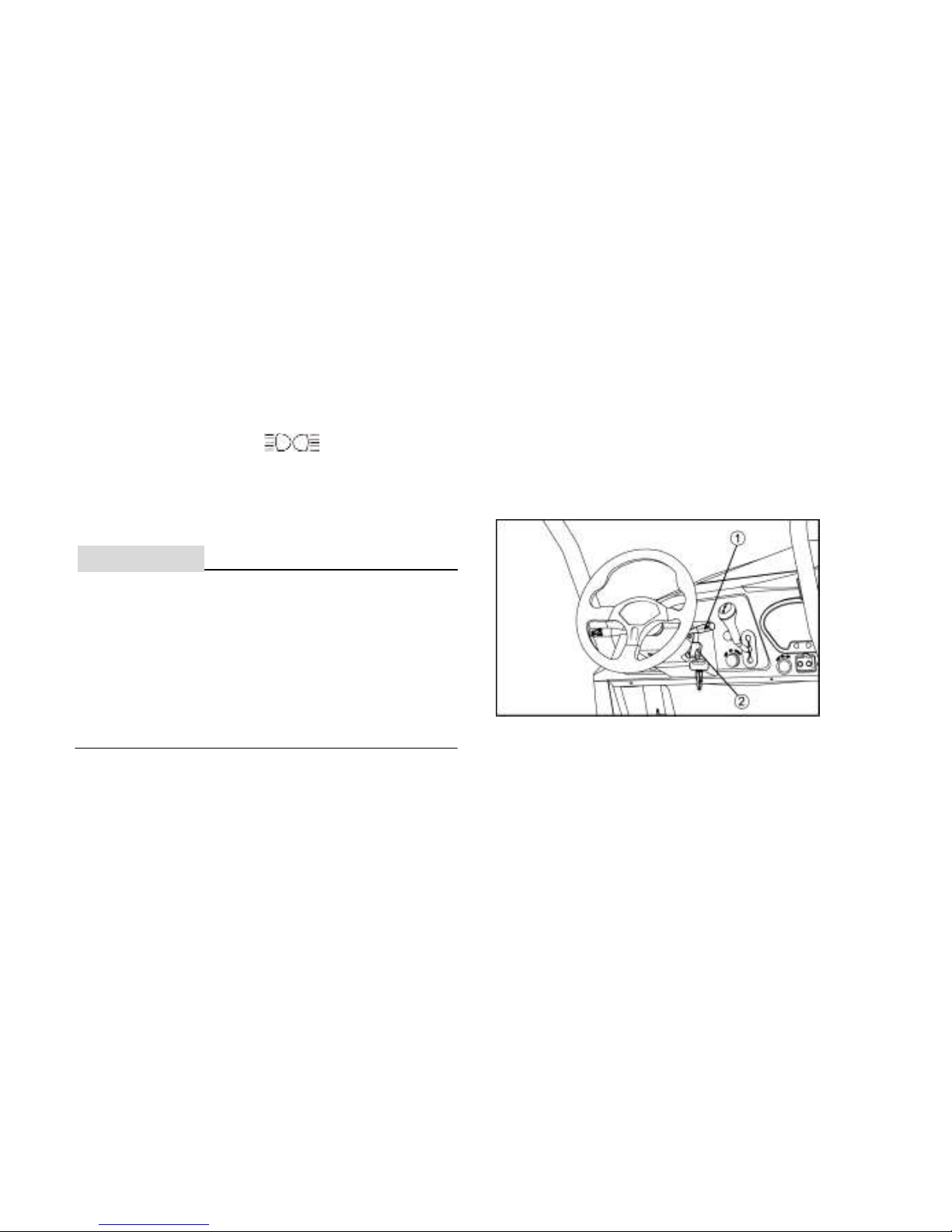
1. Horn switch 2. Ignition Switch
Press this button. The horn will work.
Page 27
4-4
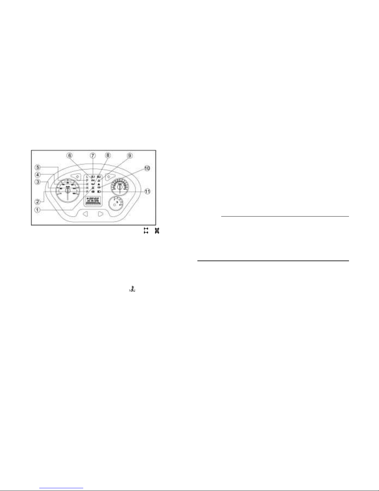
Indicator and Warning Lights
1. On-Command four-wheel-drive indicator “ ”/ “ ”
2. Parking brake indicator light “P”
3. Reverse indicator light “R”
4. Neutral indicator light “N”
5. High-range indicator light “F”
6. Position light indicator
7. On-Command differential lock indicator “DIFF. LOCK”
8. Oil Overheat Indicator
9. Coolant temperature warning light “ ”
10. Battery Power Shorted Indicator
11. High beam indicator
On-Command Differential Gear Lock
Indicator Light “DIFF. LOCK”
This indicator light and the On-Command
differential gear lock indicator in the display
come on when the On-command differential
gear lock switch is set to the “LOCK” position.
NOTE:
When the switch is set to “LOCK”, the
On-Command differential gear lock indicator
light will flash until the differential gear is
locked.
Forword-Range Indicator Light “F”
This indicator light comes on when the drive
select lever is in the “F” position.
Page 28
4-5
Neutral Indicator Light “N”
This indicator light comes on when the drive
select lever is in the “N” position.
Reverse Indicator Light “R”
This indicator light comes on when the drive
select lever is in the “R” reverse position.
Parking Brake Indicator Light “P”
This indicator light comes on when the
parking brake is applied.
NOTE:
If the indicator light flashes under any other
circumstances or the speedometer does not
show the speed while riding, have a dealer
check the speed sensor circuit.
On-Command Four-Wheel-Drive Indicator
“ ”/ “ ”
The On-Command four-wheel-drive indicator
“ ” comes on when the On-Command fourwheel-drive switch is set to the “4WD”
position.
NOTE:
● Due to the synchronizing mechanism in
the differential gear case, the four-wheeldrive indicator may not come on until the
vehicle starts moving.
Coolant Temperature Warning Light “ ”
When the coolant temperature reaches a
specified level, this light comes on to warn
that the coolant temperature is too hot. If
the light comes on during operation, stop the
engine as soon as it is safe to do so and
Page 29

4-6
allow the engine to cool down for about 15
minutes.
1CAUTION:
The engine may overheat if the vehicle is
overloaded. If this happens, reduce the
load to specification.
After restarting, make sure that the light
is out. Continuous use while the light is
on may cause damage to the engine.
High beam indicator
The light being on means headlight is at high
beam mode.
Position light indicator
The light being on means that the position
light fixed in the front headlight has been
turned on.
Coolant temperature warning indicator
“ ”
When the coolant temperature reaches to a
specified level, this light comes on to warn
that the coolant temperature is too hot. If the
light comes on during operation, stop the
engine as soon as possible. It is safe to do so
and allow the engine to cool down for about
15 minutes.
CAUTION
The engine may overheat if the UTV is
overloaded. If this happens, reduce the load
to specification.
After restarting, make sure that the light is
out. Continuous usage while the light is on
may cause damage to the engine.
Page 30
4-7
Battery Power Shorted Indicator
Shows the battery is overused. Please take
out the battery, re-charge and check the
discharged reason.
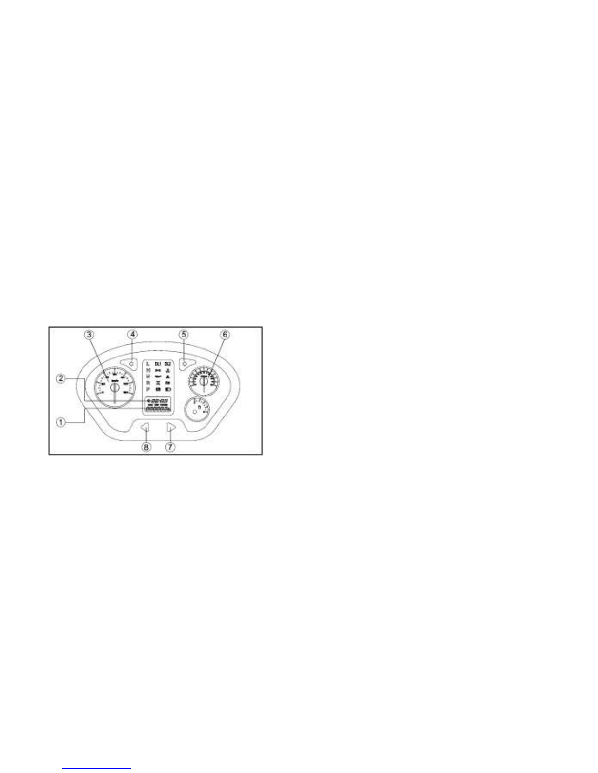
Multi-Function Display Gauge
1.“TRIP/ODO” button 2. Clock/Hour meter
3.Tachometer 4.Left turn indicator
5.Right turn indicator
6.Speedometer 7.Metric/mile button
8.Odometer/Trip meter A / Trip meter B/Clock/Hour button
The multi-function meter unit is equipped
with the following:
Speedometer (which shows the riding
speed)
Odometer (which shows the total distance
traveled)
Two trip meters (which show the distance
traveled since they were last set to zero)
Clock
Hour meter (which shows the total time
the key has been turned to “ON”)
Odometer and Trip Meter Modes
Pushing the “TRIP/ODO” button switches the
display between the odometer mode “ODO”
and the trip meter modes “A” and “B” in the
following order:
ODO→TRIP A→ TRIP B → ODO
To reset a trip meter, select it by pushing the
Page 31

4-8
“TRIP/ODO” button, and then push the
“TRIP/ODO” button for at least three seconds.
The trip meters can be used to estimate the
distance that can be traveled with a full tank
of fuel. This information will enable you to
plan future fuel stops.
NOTE:
Holding in the “TRIP/ODO” button and then
turning the key to “ON” switches the display
between “mph” and “km/h”.
Clock Mode
Pushing the button switches the
display between the clock mode “CLOCK”
and the hour meter mode “HOUR” in the
following order:
CLOCK→HOUR→CLOCK
To Set the Clock
1. Set into the clock mode.
2. Press the watch button for 3-5 seconds.
3. Press the “KM/MILE” button to set the
hours.
4. Press the “TRIP/ODO” button to set the
minutes.
5. Press the watch button for 3-5 seconds,
and then release it, the clock will begin
to work.
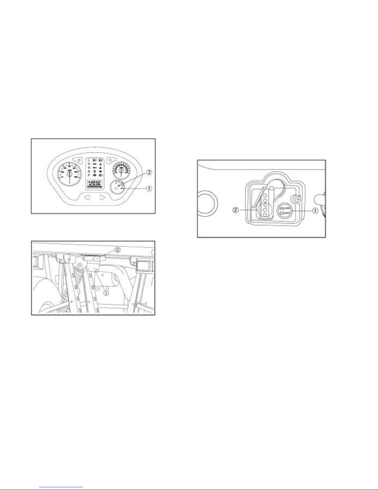
Fuel Gauge
The fuel gauge will indicate the fuel volume.
As the fuel is running out, the indicator will
turn green into red, Vice versa.
Page 32
4-9
1. Fuel meter 2. Fuel level warning indicator
1. Rear license bracket 2. Rear license light
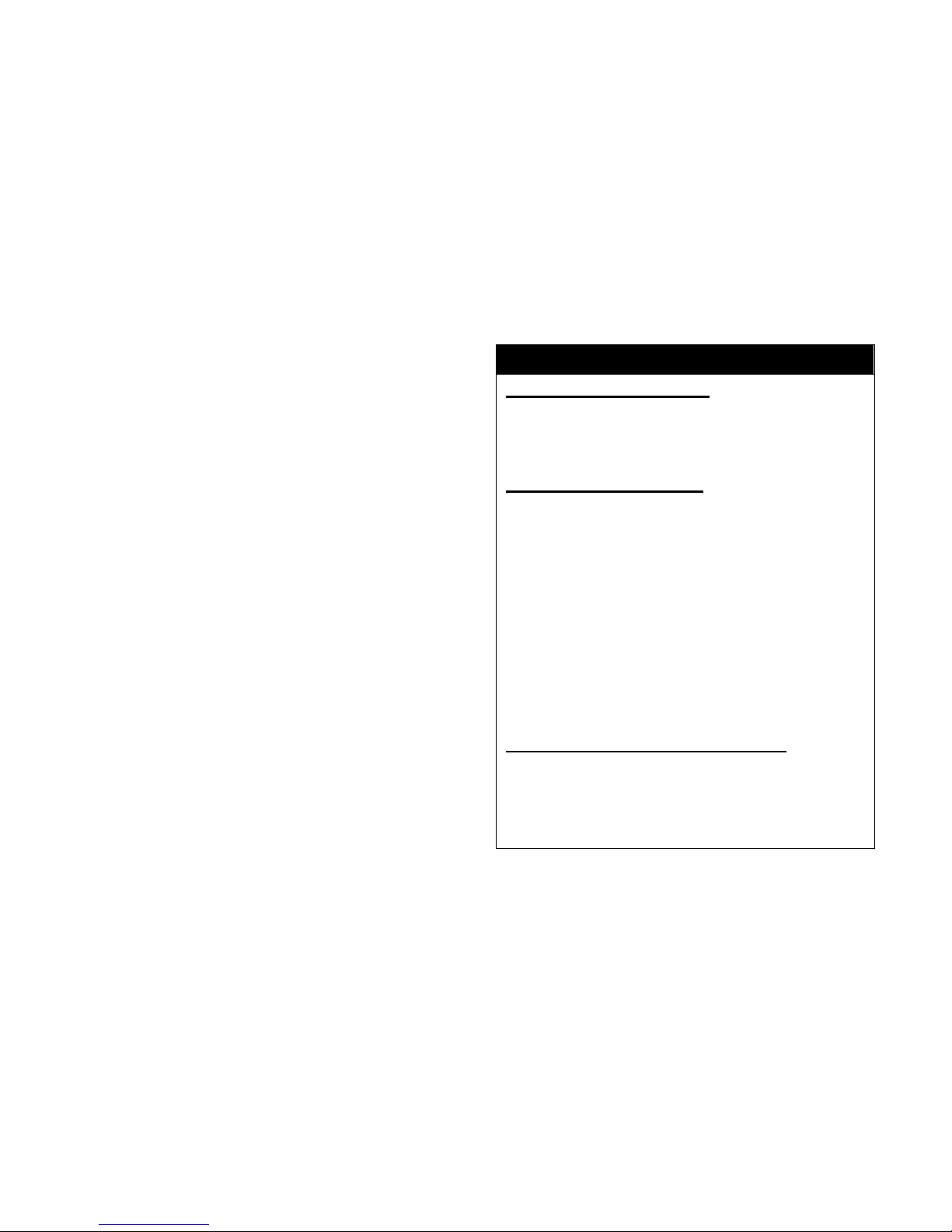
On-Command Four-Wheel–Drive and
Differential Gear Lock Switches
1. On-Command four-wheel –drive switch “2WD”/ “4 WD”
2. Differential gear lock switch “LOCK”/ “2WD”
This vehicle is equipped with an
On-Command
four–wheel-drive switch “2WD”/ “4WD”and a
differential gear lock switch “4WD”/ “LOCK”.
Select the appropriate drive according to
terrain and the conditions.
Two-wheel drive (”2WD”): Power is sup-
Page 33
4-10
plied to the rear wheels only.
Four-wheel drive (“4WD”): Power is
supplied to the rear and front wheels.
Four–wheel drive with the differential
gear locked (“4WD-LOCK”): Power is
supplied to the rear and front wheels
when the differential gear is locked
(“DIFF. LOCK”). Unlike the 4WD mode,
all wheels turn at the same speed
regardless of traction.
WARNING
POTENTIAL HAZARD
Changing from 2WD to 4WD or from
2WD to 2WD-Differential UNLOCK, or
vice-versa while the vehicle is moving.
WHAT CAN HAPPEN
The vehicle handles differently in 4WD
than in 2WD and in 2WD- Differential
UNLOCK in some circumstances.
Changing from 2WD to 4WD or from
2WD to 2WD–Differential UNLOCK, or
vice-versa while moving may cause the
vehicle to unexpectedly handle
differently. This could distract the
operator and increase the risk of losing
control and an accident.
HOW TO AVOID THE HAZARD
Always stop the vehicle before
changing from 2WD to 4WD or from
2WD to 2WD–Differential UNLOCK, or
vice-versa.
Page 34
4-11
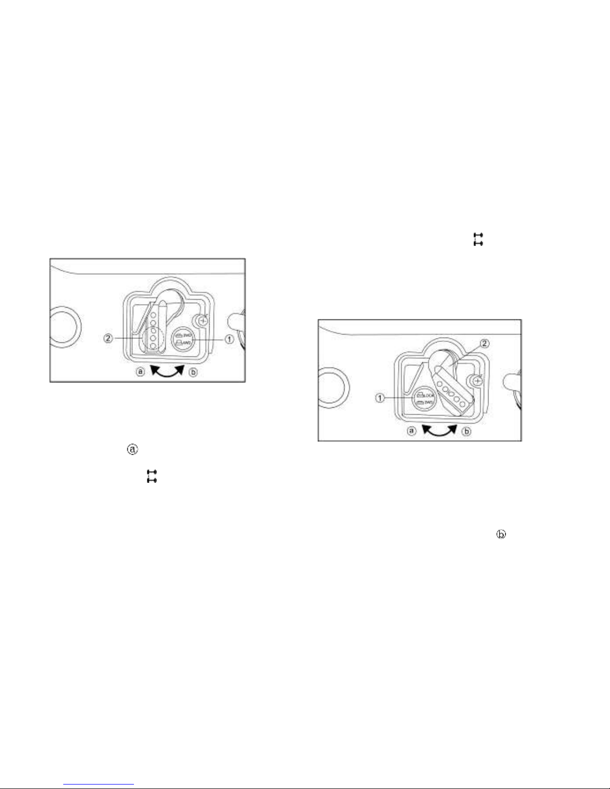
On-Command Four-Wheel-Drive Switch
“2WD/4WD”
1. On-Command four –wheel-drive switch “2WD/4WD”
2. Select lever
To change from 2WD to 4WD
stop the vehicle, be sure the select lever is
set to position ,and then set the switch to
“4WD”. When the vehicle is in 4WD, the
4WD indicator “ ” will come on in the
multi-function display.
To change from 4WD to 2WD
stop the vehicle, and then set the switch to
“2WD”。the 4WD indicator “ ” will go out in
the multi-function display.
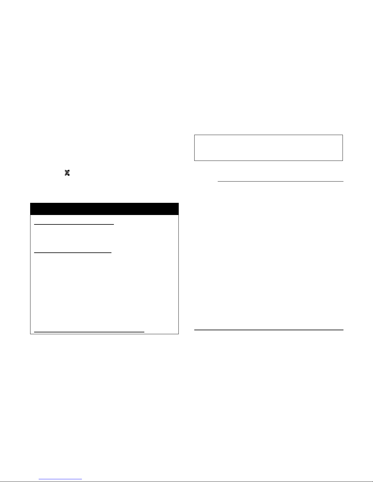
On-Command Differential Gear Lock
Switch “4WD/LOCK”
1. On-Command differential lock switch “4WD/LOCK”
2. Select lever
To lock the differential gear in 4WD, stop the
vehicle, make sure the On-Command
four-wheel-drive switch is set to “4WD”,
move the select lever to position , and then
Page 35
4-12
set the switch to “LOCK”. When the
differential gear is locked, the differential
gear lock indicator light (“DIFF. LOCK”) will
come on along with the differential gear lock
indicator “ ” in the multifunction meter unit
display. To release the differential gear lock,
stop the vehicle and set the switch to “4WD”.
WARNING
POTENTIAL HAZARD
Riding too fast while the vehicle is in
4WD-LOCK.
WHAT CAN HAPPEN
All wheels turn at the same speed when
the differential is locked, so it takes
more effort to turn the vehicle. The
amount of effort required is greater the
faster you go. You may lose control and
have an accident if you cannot make a
sharp enough turn for the speed you
are traveling.
HOW TO AVOID THE HAZARD
Always ride at a slow speed when the
vehicle is in 4WD-LOCK, and allow
extra time and distance for maneuvers.
NOTE:
When the switch is set to “LOCK”, the
differential gear lock indicator and
indicator light will flash until the
differential gear is locked.
When the indicator and indicator light are
flashing, turning the steering wheel back
and forth will help the differential gear
lock to engage.
Riding before the differential gear lock is
properly engaged (e.g. when the
indicator and indicator light are flashing)
will cause the engine speed to be limited
until engagement is complete.
Page 36

4-13
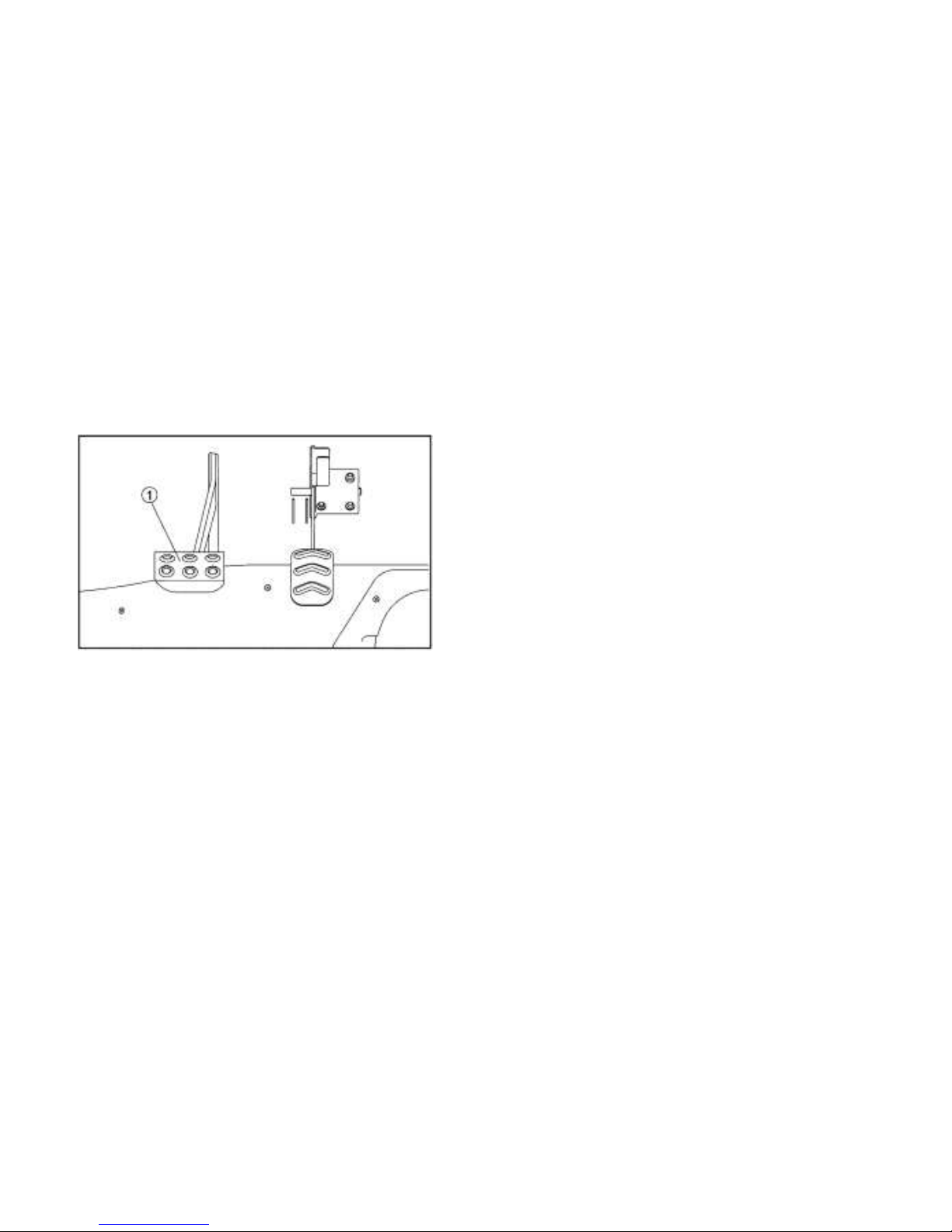
Accelerator Pedal
Press the accelerator pedal down to increase
engine speed. Spring pressure returns the
pedal to the rest position when released.
Always check that the accelerator pedal
returns normally before staring the engine.
1. Accelerator Pedal
Before starting the engine, check the
accelerator pedal to be sure it is operating
smoothly. Make sure the accelerator pedal
fully returns to the idle position as soon as it
is released.
WARNING
POTENTIAL HAZARD
Malfunction of the throttle or pedal.
WHAT CAN HAPPEN
The accelerator pedal could be hard to
operate, making it difficult to speed up
or slow down when you need to. This
could cause an accident.
HOW TO AVOID THE HAZARD
Check the operation of the accelerator
pedal before you start the engin throttle
e. If it does not work smoothly, check
for the cause. Correct the problem
before operating the vehicle. Consult a
dealer if you can’t find or solve the
problem yourself.
Page 37
4-14
Brake Pedal
Press the brake pedal to slow or stop the
vehicle.
1. Brake pedal
Parking brake pedal
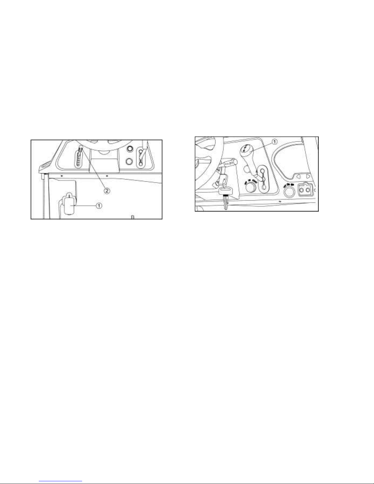
The parking brake pedal is located at the left
side of the driver’s seat. It will help hold the
vehicle from moving while parked.
To set the parking brake, Treadle the parking
pedal completely .
To release the parking brake, Pull down the
handle and treadle the parking pedal
simultaneously; Release the handle but keep
treadling the pedal for a whilw, then release
the parking pedal completely , Spring
pressure helps return the pedal to the
released position. Be sure to fully release the
parking brake before starting out, Failure to
do so may result in poor performance and
premature wearing of the rear brake and
V-belt.
Page 38
4-15
1. Parking brake pedal
2. Parking brake pedal release lever
Drive Select Lever
The drive select lever is used to shift the
vehicle into low, high, neutral and reverse
positions. (Refer to pages 6-4—6-5 for the
drive select lever operation.)
1. Drive select lever
Page 39
4-16
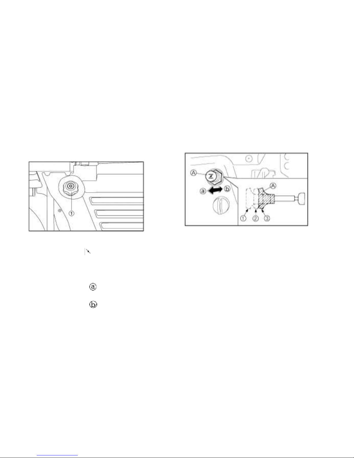
Fuel Tank Cap
Remove the fuel tank cap by turning it
counter clockwise.
1. Fuel tank cap
Starter (choke) “ ”
Starting a cold engine requires a richer
air-fuel mixture. A separate starter circuit
supplies this mixture.
Move in direction to turn on the starter
(choke)
Move in direction to turn off the starter
(choke)
Refer to “Starting a cold engine” for proper
operation. (See pages 6-1—6-3. )
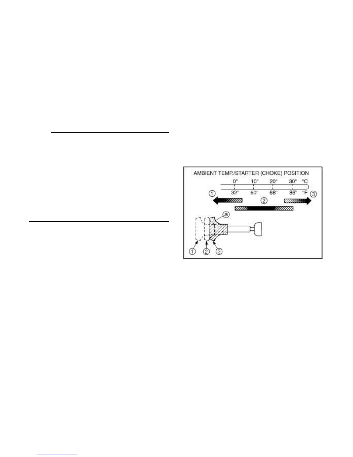
A. Starter (choke) “N” 1. Fully open
2. Half open 3. Closed
Seats
To remove a seat, pull its seat lock lever
upward, lift the front of the seat, and then
slide the seat forward and up.
Page 40

4-17
1. Driver / Passenger seat
To install a seat, insert the projection on the
rear of the seat into the seat holders and
push down on the seat at the front.
WARNING
POTENTIAL HAZARD
A loose seat.
WHAT CAN HAPPEN
The operator could lose control or the
operator or passenger could fall if the
seat is loose during operation.
HOW TO AVOID THE HAZARD
Make sure the seat is securely latched.
Page 41
4-18
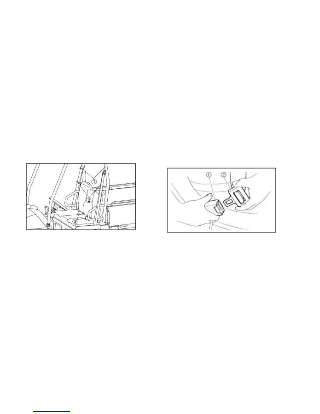
Seat belts
This vehicle is equipped with three-point seat
belts for both the operator and passenger. Always wear the seat belt while riding in
the vehicle.
1. Seat belt (×2) 2. Latch plate (×2)
3. Buckle (×2)
To wear the seat belt properly, do the
following:
1. Hold the latch plate as you pull the belt
across your lap and chest. Make sure the
belt is not twisted and is not caught on
any portion of the vehicle, your clothing,
or any equipment you are carrying.
2. Push the latch plate into the buckle until it
clicks. Pull up on the latch plate to make
sure it is secure.
1. Buckle 2. Latch plate
3. Put the lap portion of the belt low on your
hips. Push down on the buckle end of the
belt as you pull up on the shoulder part
so the belt is snug across your hips.
4. Position the shoulder belt over your
Page 42
4-19
shoulder and across your chest. The
shoulder belt should fit against your
chest. If it is loose, pull the belt out all the
way and then let it retract.
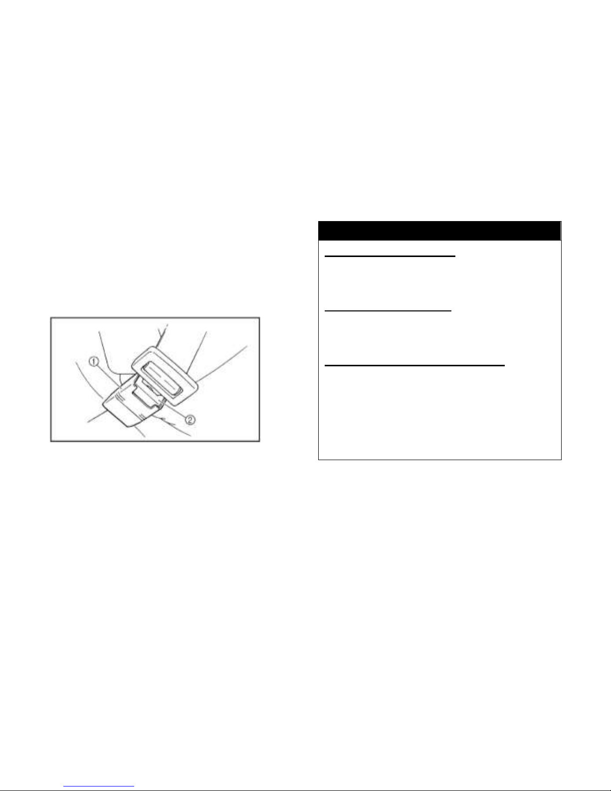
5. To release the buckle, firmly press the
release button.
1. Buckle 2. Release button
WARNING
POTENTIAL HAZARD
Not wearing the seat belt.
Wearing the seat belt improperly.
WHAT CAN HAPPEN
There is increased risk of being killed
or seriously injured in an accident.
HOW TO AVOID THE HAZARD
Always wear your seat belt when riding
in the vehicle.
Be sure the seat belt is close-fitting
across your hips and chest and is
latched securely.
Page 43
4-20
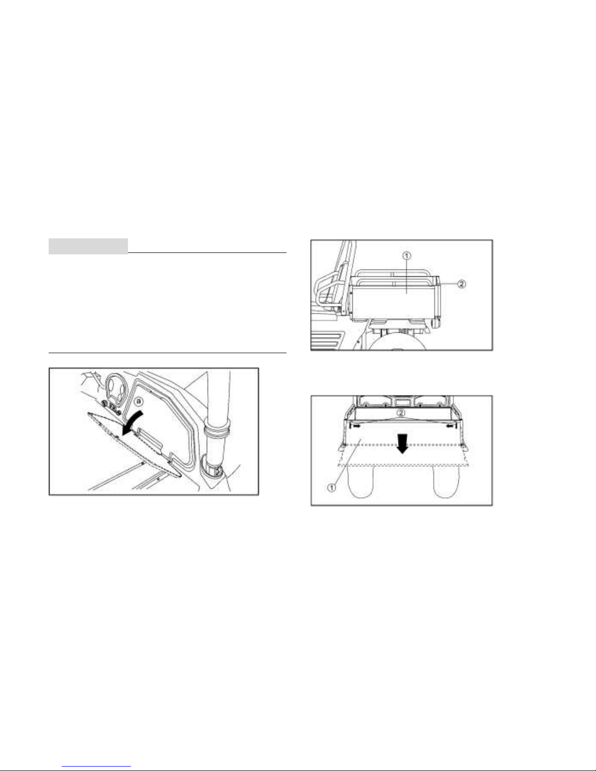
Glove Compartment
1CAUTION:
To protect from damage, do not put metal
products, like tools or sharply edged
products directly in the glove compartment. If
they must be stored, wrap them in
appropriate cushion material.
a. Open.
Cargo Bed
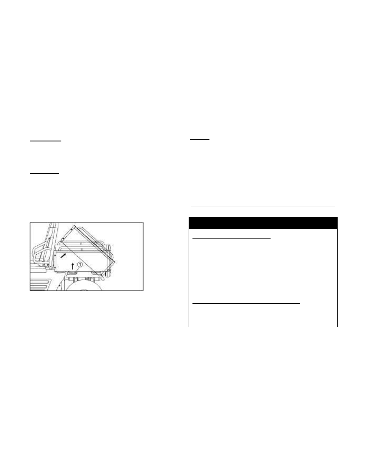
1. Cargo bed 2. Tailgate
Opening and Closing the Tailgate
1. Tailgate 2. Latch (×2)
Page 44
4-21
To open
Unhook the latches, and then lower the
tailgate.
To close
Place the tailgate in the original position, and
then hook the latches.
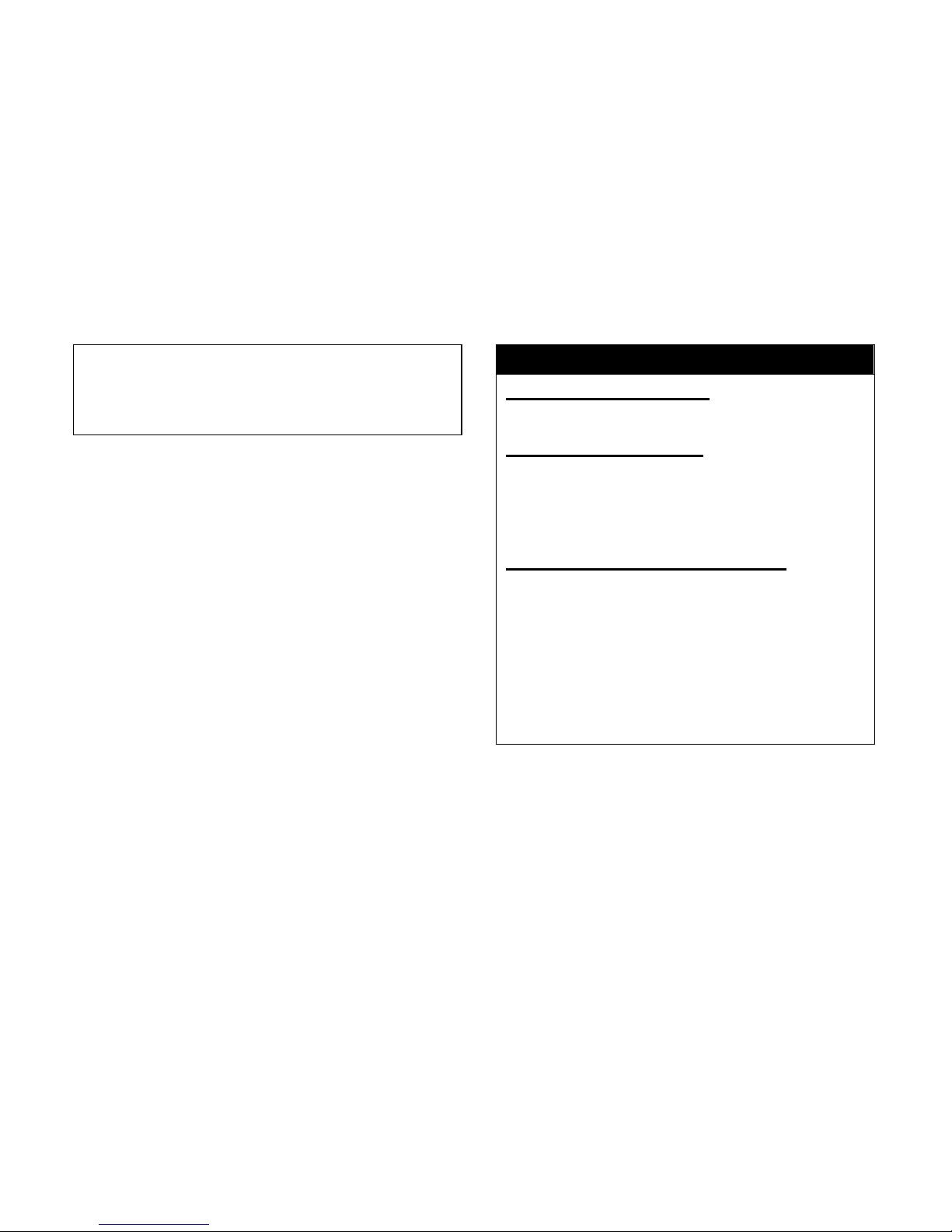
Lifting and Lowering the Cargo Bed
1. Cargo bed release lever
To lift
Push down the cargo bed release lever on
the left or right side of the vehicle, and then
slowly lift up the cargo bed until it stops.
To lower
Lower the cargo bed slowly to its original
position and be sure it is locked into place.
Maximum load limit:150kg (330lb)
WARNING
POTENTIAL HAZARD
Pinch points.
WHAT CAN HAPPEN
You or someone else could be pinched
between the cargo bed and the frame
when the bed is being lowered.
HOW TO AVOID THE HAZARD
Before closing the bed, be sure others
are standing away from the vehicle.
Page 45
4-22
Keep hands and fingers away from the
pinch points between the bed and the
frame.
WARNING
POTENTIAL HAZARD
Overloading the cargo bed
WHAT CAN HAPPEN
Could cause changes in vehicle
handling which could lead to an
accident.
HOW TO AVOID THE HAZARD
Never exceed the stated maximum load
limit for this cargo bed.
Cargo should be properly distributed
and securely attached.
Reduce speed when carrying cargo.
Allow greater distance for braking.
Page 46
4-23
WARNING
POTENTIAL HAZARD
Carrying a passenger in the cargo bed.
WHAT CAN HAPPEN
The passenger could fall, be thrown
out, or be struck by objects in the cargo
bed.
HOW TO AVOID THE HAZARD
Never carry a passenger in the cargo
bed. This cargo bed is designed to
carry cargo only.
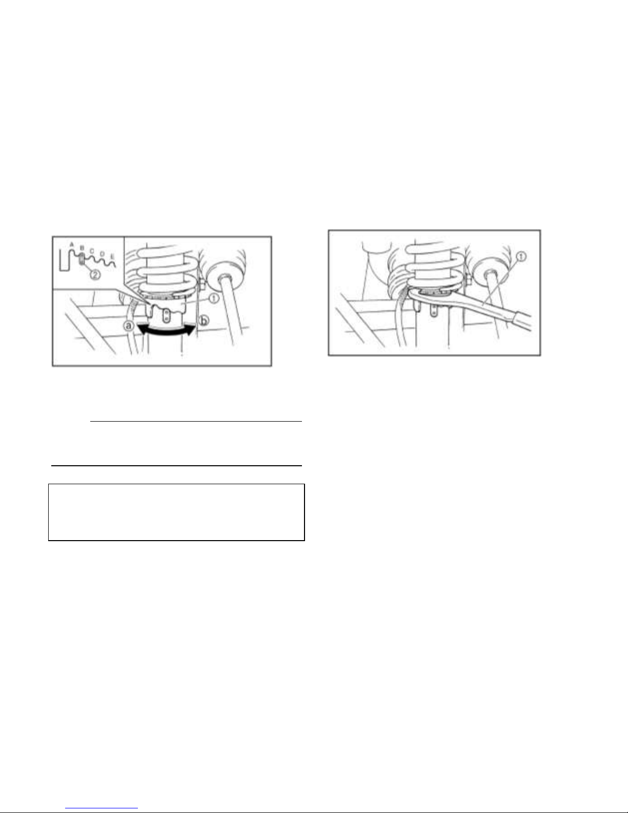
Front and Rear Shock Adjustment
The spring preload can be adjusted to suit
the operating conditions.
You can reduce preload for a softer ride, or
increase preload if frequent bottoming
occurs.
1CAUTION:
Frequent or severe bottoming can cause
increased wear or damage to the vehicle.
Adjust the spring preload as follows.
To increase the spring preload, turn the
adjusting ring in direction .
To decrease the spring preload, turn the
adjusting ring in direction .
Page 47
4-24
1. Spring preload adjusting ring
2. Position indicator
NOTE:
A special wrench can be obtained at a dealer
to make this adjustment.
Standard position: B
A-Minimum(soft)
E-Maximum(hard)
1. Special wrench
Page 48
4-25
WARNING
POTENTIAL HAZARD
Improper shock absorber adjustment.
WHAT CAN HAPPEN
Uneven adjustment can cause poor
handling and loss of stability, which
could lead to an accident.
HOW TO AVOID THE HAZARD
Always adjust the shock absorbers on
the left and right side to the same
setting.
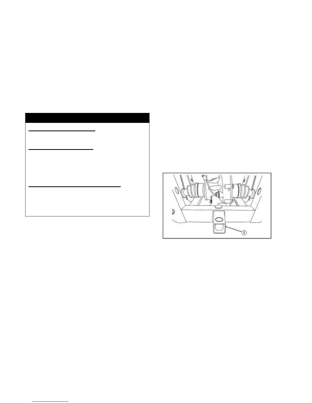
Trailer Hitch Bracket
This vehicle is equipped with a 5 cm (2 in)
receiver bracket for a standard trailer hitch.
Trailer towing equipment can be obtained at
a dealer. (See pages 6-11 - 6-13 for
precaution information.)
1. Trailer hitch bracket
Auxiliary DC Jack
The auxiliary DC jack is located at the right
side of the front panel.
Page 49

4-26
The auxiliary DC jack can be used for
suitable work lights, radios, etc.
The auxiliary DC jack should only be used
when the engine is running.
1. Auxiliary DC jack cap
1. Set the light switch to “OFF”.
2. Start the engine. (See pages 6-1-6-3.)
3. Open the auxiliary DC jack cap, and then
insert the accessory power plug into the
jack.
4. When the auxiliary DC jack is not being
used, cover it with the cap.
1. Auxiliary DC jack
Maximum rated capacity for the auxiliary
DC jack:
DC 12V, 120W (10 A)
1CAUTION:
Do not use accessories requiring more
than the above maximum capacity. This
Page 50

4-27
may overload the circuit and cause the
fuse to blow.
If accessories are used without the
engine running or with the headlights
turned on, the battery will lose its charge
and engine starting may become difficult.
Do not use an automotive cigarette
lighter or other accessories with a plug
that gets hot because the jack can be
damaged.
Page 51

5-1
PRE-OPERATION CHECKS
Before using this vehicle, check the following points:
ITEM
ROUTINE
PAGE
Brakes
● Check operation, free play, fluid level and fluid leakage.
● Fill with DOT 4 brake fluid if necessary.
5-2—5-3,8-26—8-30
Parking brake
● Check for proper operation, condition and free play.
6-6—6-7
Fuel
● Check fuel level.
● Fill with fuel if necessary.
5-4—5-5
Engine/Gear box oil
● Check oil level.
● Fill with oil if necessary.
5-6
Coolant reservoir
● Check coolant level.
● Fill with coolant if necessary.
5-6,8-15—8-16
Final gear oil /
Differential gear oil
● Check for leakage.
5-7
Accelerator pedal
● Check for proper accelerator pedal operation.
5-8—5-10
Seat belts
● Check for proper operation and belt wear.
5-10
Steering
● Check for proper operation .
5-8,5-10
Fittings and fasteners
● Check all fittings and fasteners.
5-11
Lights and switches
● Check for proper operation.
5-11
Wheels and tires
● Check tire pressure, wear and damage.
5-2—5-15,8-35—8-36
Axle boots
● Check for damage.
8-17
Instrument
● Check for compelete and right display
4-2—4-8
Light/Indicator
● Check for light / indicator operation
4-2—4-8
Page 52
5-2
WARNING
POTENTIAL HAZARD
Failure to inspect the vehicle before
operating. Failure to properly maintain
the vehicle.
WHAT CAN HAPPEN
Increases the possibility of an accident
or equipment damage.
HOW TO AVOID THE HAZARD
Always inspect your vehicle each time
you use it to make sure the vehicle is in
safe operating condition. Always follow
the inspection and maintenance
procedures and schedules described in
the Owner’s Manual.
Brakes
Always check brake pedal travel and the brake
fluid reservoir level before each use of the
vehicle. When applied, the brake pedal should
feel firm. Any sponginess would indicate a
possible fluid leak or low brake fluid level, which
must be corrected before riding.
If you discover any irregularities in brake
system operation, including excessive pedal
travel, contact your dealer for proper diagnosis
and repairs.
Front and Rear Brakes
Brake Pedal
Check for correct brake pedal free play. If the
brake pedal free play is incorrect, have a dealer
adjust it. (See pages 8-26-8-33.)
Page 53

5-3
Check the operation of the brake pedal. It
should move smoothly and there should be a
firm feeling when the brakes are applied. If not,
have the vehicle inspected by a dealer.
Brake Fluid Level
Check the brake fluid level.
Add fluid if necessary. (See pages 8-28)
Recommended brake fluid: DOT 4
Brake Fluid Leakage
Check to see if any brake fluid is leaking out of
the pipe joints or the brake fluid reservoir.
Apply the brakes firmly for one minute. If there
is any leakage, have the vehicle inspected by a
dealer.
Brake Operation
Test the brakes at slow speed after starting out
to make sure they are working properly. If the
brakes do not provide proper braking
performance, inspect the brake system. (See
pages 8-26—8-29.)
Page 54
5-4
WARNING
POTENTIAL HAZARD
Driving with improperly operating brakes.
WHAT CAN HAPPEN
You could lose braking ability, which
could lead to an accident.
HOW TO AVOID THE HAZARD
Always check the brakes at the start of
every ride. Do not operate the vehicle if
you find any problem with the brakes. If
a problem cannot be corrected by the
adjustment procedures provided in this
manual, have the vehicle inspected by a
dealer.
Fuel
Make sure there is sufficient gasoline in the
tank.
Recommended fuel:
Unleaded gasoline only
Fuel tank capacity:
13.5L ( 2.97lmp gal, 3.57US gal )
1CAUTION:
Use only unleaded gasoline. The use of
leaded gasoline will cause severe damage to
internal engine parts, such as the valves and
piston rings, as well as to the exhaust system.
Page 55
5-5
Your engine has been designed to use regular
unleaded gasoline with a pump octane number
([R+M] /2) of 86 or higher, or research octane
number of 93 or higher. If knocking or pinging
occurs, use a different brand of gasoline or
premium unleaded fuel. Unleaded fuel will
give you longer spark plug life and reduced
maintenance cost.
Gasohol
There are two types of gasohol; gasohol
containing ethanol and that containing methanol.
Gasohol containing ethanol can be used if
ethanol content does not exceed 10%. Gasohol
containing methanol is not recommended by
because it may cause fuel system damage or
vehicle performance problems.
WARNING
POTENTIAL HAZARD
Improper care when refueling.
WHAT CAN HAPPEN
Fuel can spill, which can cause a fire and
severe injury.
Fuel expands when it heats up. If the
fuel tank is overfilled, fuel could spill out
due to heat from the engine or the sun.
HOW TO AVOID THE HAZARD
Do not overfill the fuel tank. Be careful
not to spill fuel, especially on the engine
or exhaust pipe. Wipe up any spilled
fuel immediately. Be sure the fuel tank
cap is closed securely.
Page 56

5-6
Engine Oil
Make sure the engine oil is at the specified level.
Add oil as necessary. (See pages 8-7 —8-10.)
1CAUTION:
In order to prevent clutch slippage (since
the engine oil also lubricates the clutch), do
not mix any chemical additives. Do not
use oils with a diesel specification of “CD”
or oils of a higher quality than specified. In
addition, do not use oils labeled “ENERGY
CONSERVING II” or higher.
Make sure that no foreign material enters
the crankcase.
Recommended engine oil type and
quantity:
See page 10-2
Coolant
Check the coolant level in the coolant reservoir
when the engine is cold. (The coolant level will
vary with engine temperature.) The coolant
level is satisfactory if it is between the minimum
and maximum level marks on the coolant
reservoir. If the coolant level is at or below the
minimum level mark, add additional coolant to
bring the level up to maximum level mark. If
coolant is not available, add distilled water.
Change the coolant every two years. (See
pages 8-15—8-17) for details.
1CAUTION:
Hard water or salt water is harmful to the engine.
You may use soft water if you cannot get
distilled water.
Coolant reservoir capacity
(up to the maximum level mark):
0.627L(0.555lmp qt, 0.663US qt)
Page 57
5-7
WARNING
POTENTIAL HAZARD
Removing the radiator cap when the
engine and radiator are still hot.
WHAT CAN HAPPEN
You could be burned by hot fluid and
steam blown out under pressure.
HOW TO AVOID THE HAZARD
Wait for the engine to cool before
removing the radiator cap. Always use a
thick rag over the cap. Allow any
remaining pressure to escape before
completely removing the cap.
Final Gear Oil
Make sure the final gear oil is at the specified
level. Add oil as necessary. (See pages 8-14
—8-15 for details.)
Recommended oil:
SAE 80 API GL-4 Hypoid gear oil
If desired, an SAE 80W90 hypoid gear oil may
be used for all conditions.
NOTE:
GL-4 is a quality and additive rating, GL-5 or
GL-6 rated hypoid gear oils may also be used.
Differential Gear Oil
Make sure the differential gear oil is at the
specified level. Add oil as necessary. (See
pages 8-16—8-17 for details.)
Recommended oil:
SAE 80 API GL-5 Hypoid gear oil
Page 58

5-8
Throttle Pedal
Check to see that the Throttle pedal operates
correctly. It must operate smoothly and fully
spring back to the idle position when released.
Have a dealer repair as necessary for proper
operation.
WARNING
Failure to check or maintain proper
operation of the throttle system can result in
an accident and lead to serious injury or
death if the throttle pedal sticks during
operation.
Never start or operate this vehicle if it has a
sticking or improperly operating throttle
pedal.
Immediately contact your dealer for service
if throttle problems arise.
Always check the pedal for free movement
and return before starting the engine and
occasionally during operation.
Page 59
5-9
Throttle Free play
If the throttle pedal has excessive play due to
cable stretch or mis-adjustment, it will cause a
delay in throttle response, especially at low
engine speed. The throttle may also not open
fully. If the throttle pedal has no free play, the
throttle may be hard to control, and the idle
speed may be erratic.
Check the throttle pedal free play , Adjust the
free play If necessary.
Throttle Freeplay Inspection
1. Lift the parking brake to the top to park the
car.
2. Apply the brakes. Start the engine. Allow it
to warm up thoroughly.
3. Measure the distance the throttle pedal
moves before the engine begins to pick up
speed. Free play should 1/16 to 1/8
inches(1.5-3mm).
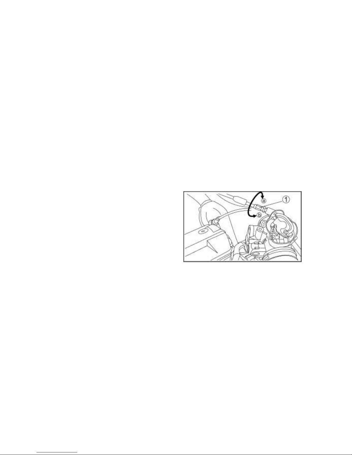
Throttle Free play Adjustment
1. Remove both seats. Remove the middle
cover of the engine, ( see PAGE 8-6 )
2. Loose the nut of throttle rope on the valve,
Spin the throttle rope inside/ outside to
increase the throttle pedal’s moving
distance to 1.5-3 mm.
1.Throttle Cable column nut
3. Fix the nut.
4. Resume the center cover and seat to their
position
Page 60

5-10
Steering Wheel Inspection
Check the steering wheel for specified free play
and smooth operation。
1. Position the vehicle on level ground.
2. Lightly turn the steering wheel left and right.
3. There should be 0.8″-1.0″ (20-25 mm)
of free play.
If there is excessive free play or strange noises,
or the steering feels rough or″catchy, ″have
the steering system inspected by an authorized
dealer。
Seat Belts
Make sure that both seat belts are not frayed or
damaged.
The seat belt must move smoothly when pulled
out and retract on its own when released. The
latch plate should click securely into the buckle
and release when the release button is pushed
firmly. Wash off any dirt or mud which could
affect operation. Have a dealer repair as
necessary for proper operation.
Fittings and Fasteners
Always check the tightness of chassis fittings
and fasteners before a ride. Take the vehicle
to a dealer or refer to the Service Manual for
correct tightening torque.
Lights
Check the headlights and tail/brake lights to
make sure they are in working condition.
Repair as necessary for proper operation.
Switches
Check the operation of all switches. Have a
dealer repair as necessary for proper operation.
Page 61
5-11
Tires
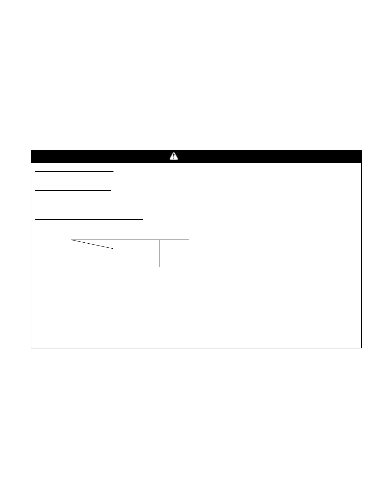
WARNING
POTENTIAL HAZARD
Operating this vehicle with improper tires, or with improper or uneven tire pressure.
WHAT CAN HAPPEN
Use of improper tires on this vehicle, or operation of this vehicle with improper or uneven tire
pressure, may cause loss of control, increasing your risk of accident.
HOW TO AVOID THE HAZARD
1. The tires listed below have been approved by Motor Manufacturing corporation of
America for this model. Other tire combinations are not recommended.
2. The tires should be set to the recommended pressure:
● Recommended tire pressure
Front 140kpa (1.4 kgf/cm2, 20psi)
Rear 140kpa (1.4 kgf/cm2, 20psi)
Check and adjust tire pressures when the tires are cold.
Tire pressures must be equal on both sides.
3. Tire pressure below the minimum specified could cause the tire to dislodge from the rim
Type
Size
Front
25×8-12
6PR
Rear
25×10-12
6PR
Page 62

5-12
under severe riding conditions. The following are minimums:
Front 126kpa (1.26kgf/cm2, 18psi)
Rear 126kpa (1.26kgf/cm2, 18psi)
4. Use no more than the following
Pressures when seating the tire beads.
Front 250kpa (2.5kgf/cm2, 36psi)
Rear 250kpa (2.5kgf/cm2, 36psi)
Higher pressures may cause the tire to burst. Inflate the tires very slowly and carefully.
Fast inflation could cause the tire to burst.
Page 63
5-13
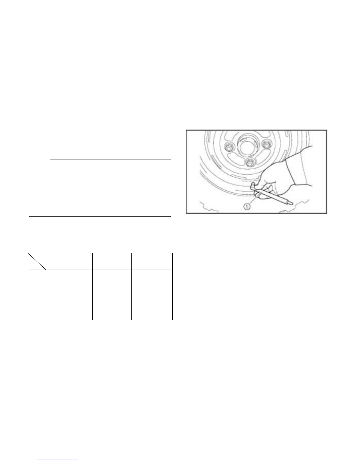
How to measure tire pressure
Use the tire pressure gauge.
NOTE:
The tire pressure gauge is included as standard
equipment. Make two measurements of the
tire pressure and use the second reading.
Dust or dirt in the gauge could cause the first
reading to be incorrect.
Set pressure with tires cold.
Set tire pressures to the following
specifications:
Recommended
pressure
Minimum
Maximum
Front
140kpa
(1.4kgf/ cm2,
10psi)
126kpa
(1.26kgf/ cm2,
9psi)
250kpa
(2.5gf/ cm2,
11psi)
Rear
140kpa
(1.4kgf/ cm2,
10psi)
126kpa
(1.26kgf/ cm2,
9psi)
250kpa
(2.5kgf/ cm2,
11psi)
1. Tire pressure gauge
Page 64
5-14
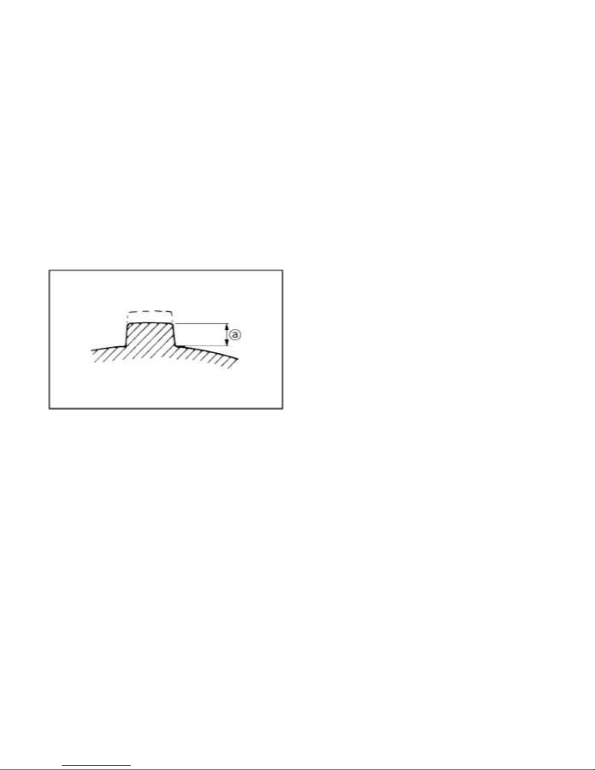
Tire Wear Limit
When the tire groove decreases to 3 mm (0.12
in) due to wear, replace the tire.
a. Tire wear limit
Tires for Public use
If you need to drive the UTV on public road,
please switch to the tires with public road use
tread, which can explore its performance.
Always use the public road use tires according
to tires maker’s recomment.
Page 65
6-1
OPERATION
WARNING
POTENTIAL HAZARD
Operating vehicle without being
familiar with all controls.
WHAT CAN HAPPEN
Loss of control, which could cause an
accident or injury.
HOW TO AVOID THE HAZARD
Read the Owner’s Manual carefully. If
there is a control or function you do
not understand, ask your dealer.
Starting a cold engine
WARNING
POTENTIAL HAZARD
Freezing control cables in cold
weather.
WHAT CAN HAPPEN
You could be unable to control the
vehicle, which could lead to an
accident or collision.
HOW TO AVOID THE HAZARD
When riding in cold weather, always
make sure all control cables work
smoothly before you begin riding.
1. Apply the brake.
2. Shift the drive select lever into the
neutral position.
Page 66
6-2
NOTE:
● When the drive select lever is in the
neutral position, the neutral indicator
light should come on. If the neutral
indicator light does not come on, ask a
dealer to inspect the electric circuit.
● The engine can be started in any gear if
the brake is applied. However, it is
recommended to shift into neutral before
starting the engine.
3. Use the starter (choke) in reference to
the figure:
Position ① : Cold engine start ambient
temperature below5℃ (41°F)
Position ② : Cold engine start ambient
temperature at 0℃
(32°F-30°(86°F) and warming
up position.
Position ③ : Cold engine start ambient
temperature above 25℃(77°F)
and warm engine start
position.
a. Starter(choke) 1. Fully open
2. Half open 3. Closed
4. With your foot off the accelerator pedal,
start the engine by turning the key to
“START”.
Page 67

6-3
NOTE:
If the engine fails to start, release the key,
and then try starting again. Wait a few
seconds before the next attempt. Each
cranking should be as short as possible to
preserve battery energy. Do not crank the
engine more than 5 seconds on each
attempt.
5. If the engine is started with the starter
(choke) in position①, the starter (choke)
should be returned to Position ② to
warm up the engine. If the engine is
started with the starter (choke) in
Position ②, keep the starter (choke) in
this position to warm up the engine.
6. Continue warming up the engine until it
idles smoothly and return the starter
(choke) to position ③ before riding.
CAUTION:
See the “Engine break-in”section prior to
operating the engine for the first time.
Starting a warm engine
To start a warm engine, refer to the“Starting
a cold engine”section. The starter (choke)
should not be used. Press the accelerator
pedal slightly.
Jump-starting
Jump-starting the vehicle should be avoided.
The battery should be removed and charged
instead. However, if the vehicle must be
jumpstarted, proceed as follows.
1. Turn the key to“OFF”.
2. Open the hood. (See pages 8-7—8-8 for
hood opening and closing procedures.)
3. Remove the battery compartment cover.
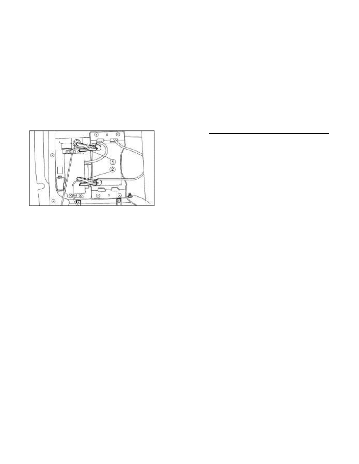
4. Using a charged 12V battery, connect
the positive lead of the jumper cable to
the positive terminal of the battery in the
vehicle and the other end of the positive
lead to the positive terminal of the
charged battery.
Page 68
6-4
1. Jumper cable positive lead
2. Jumper cable negative lead
5. Connect the negative lead of the jumper
cable to the negative terminal of the
charged battery and the other end of the
negative lead to an unpainted metal
surface of the vehicle.
NOTE:
Do not connect the negative lead of the
jumper cable to the negative terminal of the
battery in the vehicle.
Be especially careful not to:
● touch the positive lead of the jumper
cable to the negative lead.
● reverse the polarity of the jumper cables
when connecting to the batteries-battery
explosion and/or serious damage to the
electrical system may occur.
6. Start the engine. (Refer to“Starting a
cold engine”on pages 6-1—6-3.)
7. After the engine starts, disconnect the
negative lead of the jumper cable from
the vehicle and charged battery, and
then disconnect the positive lead of the
jumper cable from the charged battery
and the battery in the vehicle.
8. Install the battery compartment cover.
9. Close the hood.
Page 69
6-5
Warming up
To get maximum engine life, always warm up
the engine before starting off. Never
accelerate hard with a cold engine! To see
whether or not the engine is warm, check if it
responds to the throttle normally with the
starter (choke) turned off.
Drive select lever operation and reverse
driving
CAUTION:
Before shifting, you must stop the vehicle
and take your foot off the accelerator pedal.
Otherwise, the transmission may be
damaged.
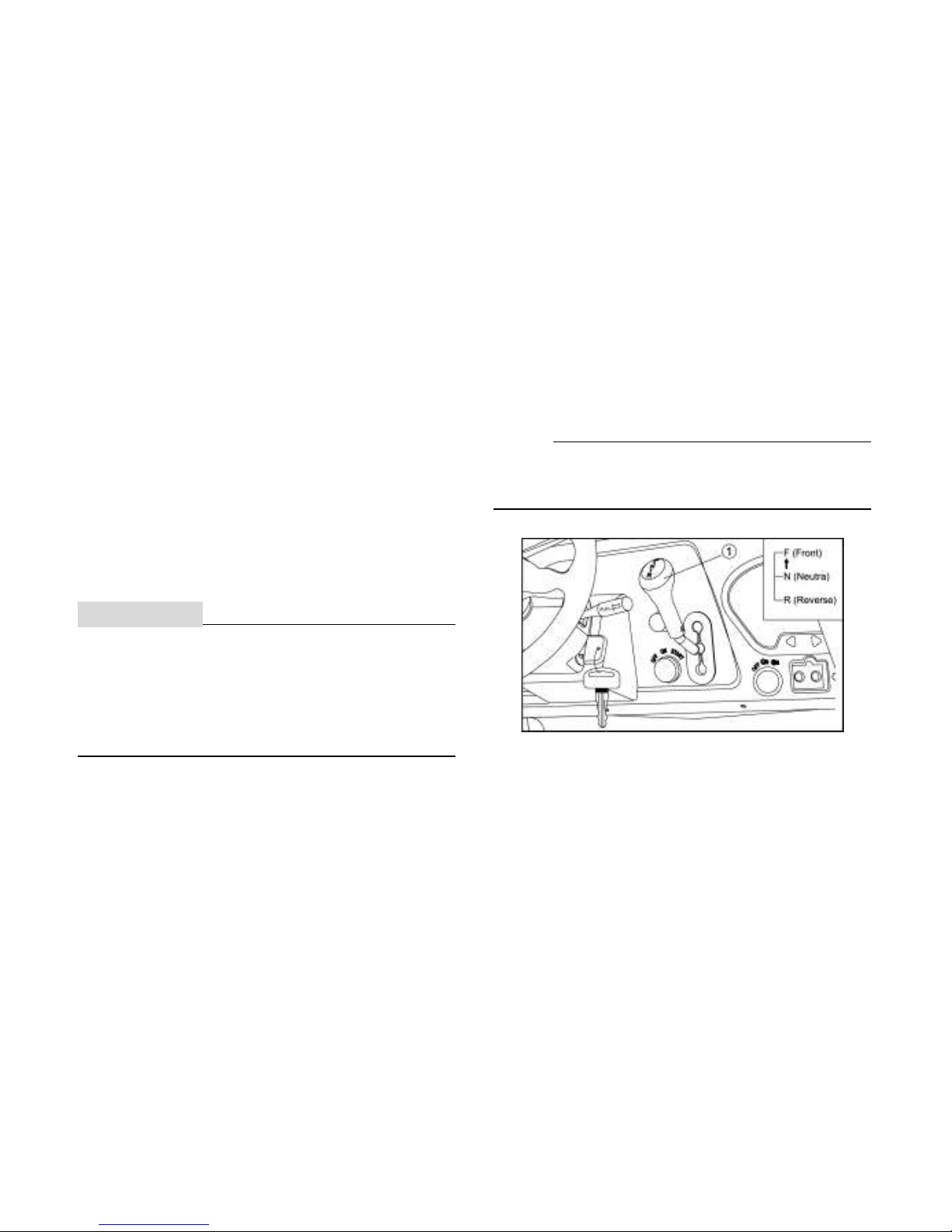
Shifting: Neutral to Front
1. Stop the vehicle. Keep your foot off the
accelerator pedal.
2. Apply the brakes, then shift by moving
the drive select lever along the shift
guide.
NOTE:
Make sure that the drive select lever is
completely shifted into position.
1. Drive select lever
3. Release the brakes and press the
accelerator pedal gradually.
Page 70
6-6
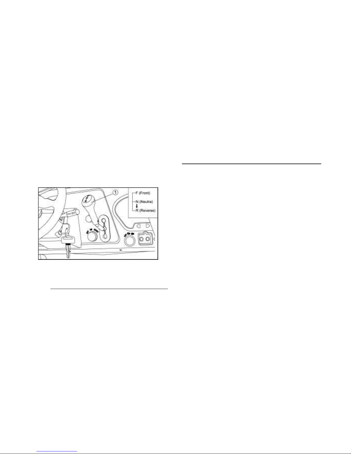
Shifting: Neutral to Reverse
1. Stop the vehicle. Keep your foot off the
accelerator pedal.
2. Apply the brake pedal.
3. Shift from neutral to reverse or vice
versa by moving the drive select lever
along the shift guide.
1. Drive select lever
NOTE:
● When in reverse, the reverse indicator
light should be on. If the light does not
come on, ask a dealer to inspect the
reverse indicator light electrical circuit.
● Due to the synchronizing mechanism in
the engine, the light may not come on
until the vehicle starts moving.
4. Check behind for people or obstacles,
then release the brake pedal.
5. Press the accelerator pedal gradually
and continue to watch to the rear while
backing.
Page 71
6-7
WARNING
POTENTIAL HAZARD
Improperly operating in reverse.
WHAT CAN HAPPEN
You could hit an obstacle or person
behind you, resulting in serious injury.
HOW TO AVOID THE HAZARD
When you shift into reverse, make
sure there are no obstacles or people
behind you. When it is safe to
proceed, go slowly.
Vehicle Break-in Period
The break-in period for your new UTV
vehicle is the first 25 hours of operation, or
the time it takes to use the first three tanks
full of gasoline. No single action on your part
is as important as a proper break-in period.
Careful treatment of a new engine and drive
components will result in more efficient
performance and longer life for these
components. Perform the following
procedures carefully.
● Excessive heat build-up during the first
three hours of operation will damage
close-fitted engine parts and drive
components. Do not operate at full
throttle or high speeds during the first
three hours of use.
● Use of any engine oil not mentioned in
this manual will cause severe damage to
the engine。
Engine Break-In
There is never a more important period in the
Page 72

6-8
life of your vehicle than the period between
zero and 25hours.
For this reason, we ask that you carefully
read the following material. Because the
engine is brand new, you must not put an
excessive load on it for the first several
hours of running.
During the first 25 hours, the various parts in
the engine wear and polish themselves to
the correct operating clearances.
During this period, prolonged full throttle
operation or any condition which might result
in excessive engine heating must be avoided.
However, momentary (2-3 seconds
maximum) full throttle operation under load
does not harm the engine.
Each full throttle acceleration sequence
should be followed with a substantial rest
period for the engine by cruising at lower
r/min so the engine can rid itself of the
temporary build up of heat. If any
abnormality is noticed during this period,
consult a dealer.
0-10 Hours:
Avoid continuous operation above half
throttle. Allow a cooling off period of five to
ten minutes after every hour of operation.
Vary the speed of the vehicle from time to
time. Do not operate it at one set throttle
position.
10-25 Hours:
Avoid prolonged operation above 3/4 throttle.
Rev the vehicle freely but do not use full
throttle at any time.
After Break-In:
The vehicle can now be operated normally.
Brake System Break-in
Apply only moderate braking force for the
first 50 stops. Aggressive or overly forceful
Page 73
6-9
braking when the brake system is new could
damage brake pads and rotors.
CVT Break-in (Clutches/Belt)
A proper break-in of the clutches and drive
belt will ensure a longer life and better
performance. Break in the clutches and belt
by operating at slower speeds during the
break-in period as recommended. Pull only
light loads. Avoid aggressive acceleration
and high speed operation during the break-in
period.
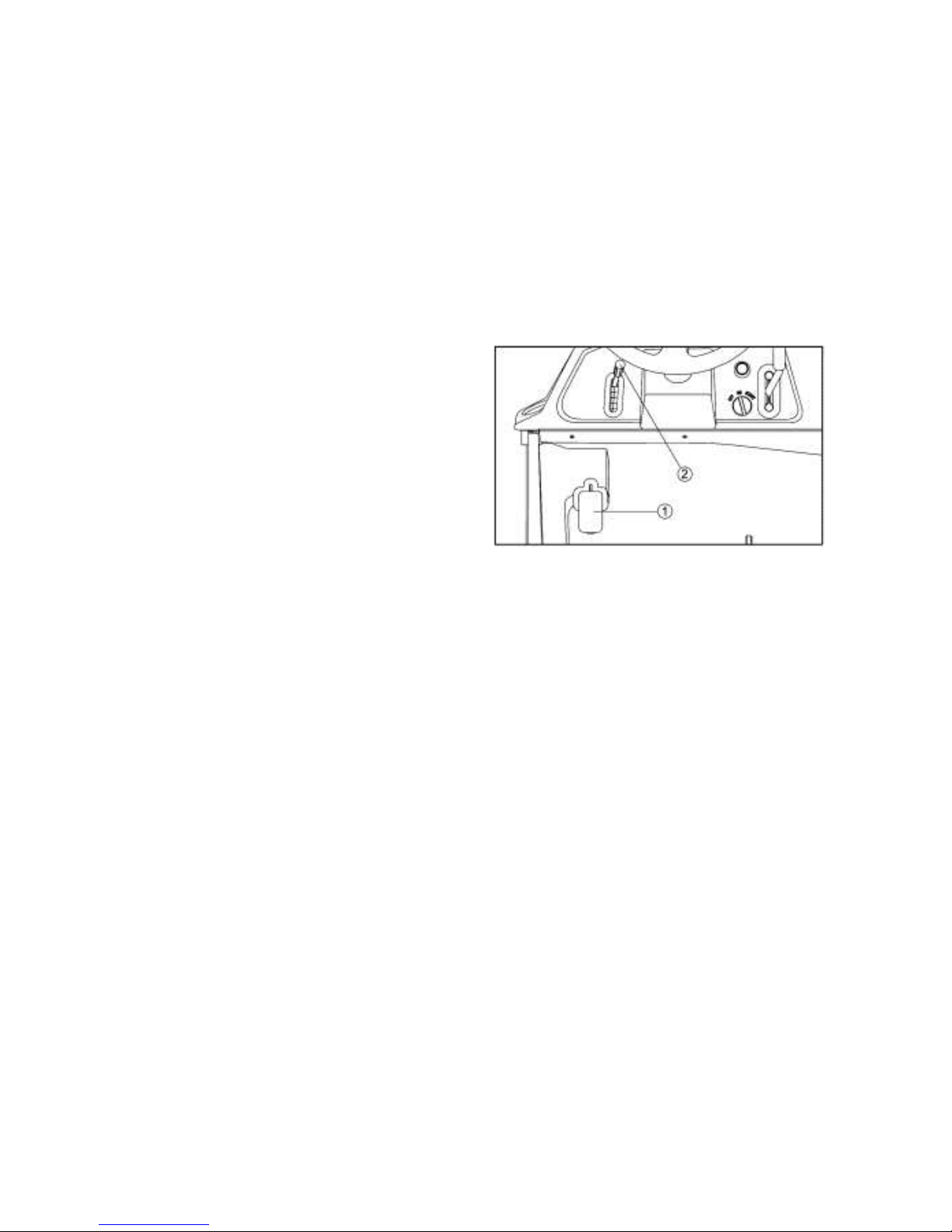
Parking
When parking, stop the engine and shift the
drive select lever into the neutral position.
Apply the parking brake to help prevent the
vehicle from rolling.
1. Parking brake pedal
2. Parking brake pedal release lever
Page 74
6-10
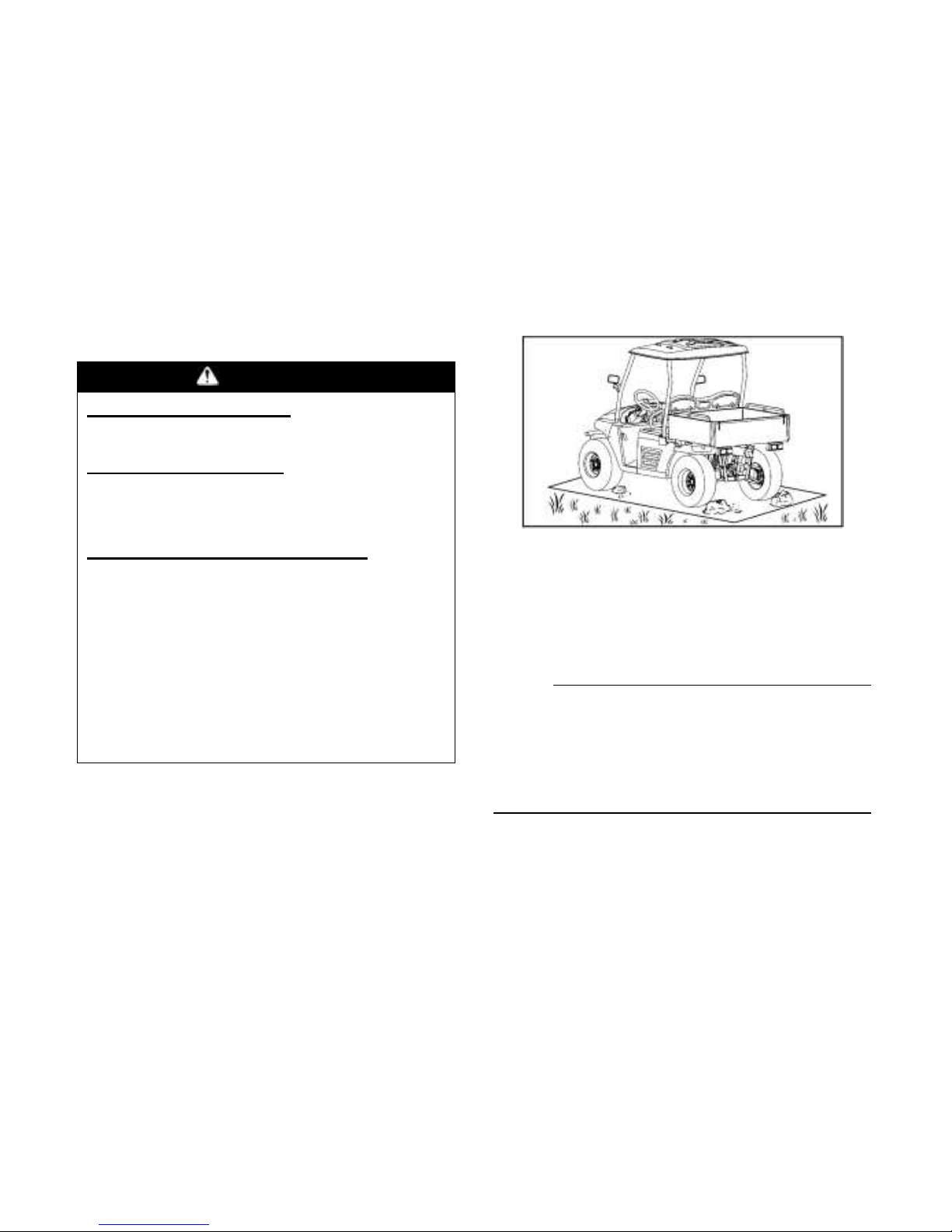
Parking on a slope
WARNING
POTENTIAL HAZARD
Parking on a hill or other incline.
WHAT CAN HAPPEN
The vehicle could roll out of control,
increasing the chance of an accident.
HOW TO AVOID THE HAZARD
Avoid parking on hills or other inclines.
If you must park on an incline, apply
the parking brake, and block the front
and rear wheels with rocks or other
objects. Do not park the vehicle at all
on hills that are so steep you could not
walk up them easily.
1. Bring the vehicle to a stop by applying
the brakes.
2. Stop the engine.
3. With the brakes applied, set the parking
brake.
NOTE:
Like many other vehicles, the parking brake
acts on the rear wheels. For the parking
brake to have the effect of braking all four
wheels, shift to 4WD before stopping the
engine.
Page 75

6-11
Accessories and loading
Accessories
Accessories can affect the handing and
control of your vehicle. Keep the following in
mind when considering an accessory or
operating a vehicle which has accessories.
● Choose only accessories designed for
your vehicle. Your dealer has a variety of
genuine accessories. Other accessories
may also be available on the market.
However, it is not possible for to test all
non accessories, nor have any control
over the quality or suitability of them.
Choose a genuine accessory, or one that
is equivalent in design and quality.
● Accessories should be rigidly and
securely mounted . An accessory which
can shift position or come off while you
are operating could affect your ability to
control the vehicle.
● Do not mount an accessory where it
could interfere with your ability to control
the vehicle. Examples include (but are
not limited to) an object that limits your
ability to turn the steering wheel or one
that limits your view.
● Use extra caution when driving a vehicle
with accessories. The vehicle may
handle differently than it does without
accessories.
Page 76

6-12
Loading
Cargo or a trailer can change the stability
and handling of a vehicle.
You must use common sense and good
judgment when carrying cargo or towing a
trailer. Keep the following points in mind:
● Never exceed the weight limits shown.
An overloaded vehicle can be unstable.
MAXIMUM LOADING LIMIT
● Vehicle loading limit (total weight of
cargo, operator, passenger and
accessories, and tongue weight):
370 Kg (814 lb)
● Cargo bed:150Kg (330 lb)
● Trailer hitch:
Pulling load (total weight of trailer
and cargo):552Kgf (1,214lbf)
Tongue weight (vertical weight on
trailer hitch point):50Kgf (110lbf)
● Choose a trailer hitch drawbar designed
for use with a 5 cm (2in) receiver.(See
page 4-25 for more information)
● Do not exceed the maximum tongue
weight. You can measure tongue weight
with a bathroom scale. Put the tongue of
the loaded trailer on the scale with the
tongue at hitch height. Adjust the load in
the trailer, if necessary, to reduce the
weight on hitch. If you are carrying cargo
and towing a trailer, include the tongue
weight in the maximum vehicle load limit.
● Load cargo in the cargo bed as close to
the center of the vehicle as possible and
tie it down using the cargo hooks
equipped on the cargo bed.
● Tie down cargo securely in the trailer.
Make sure cargo in the trailer cannot
move around. A shifting load can cause
Page 77
6-13
an accident.
● Make sure the load does not interfere
with controls or your ability to see where
you are going.
● Drive more slowly than would without a
load. The more weight you carry, the
slower you should go. Although
conditions vary, it is good practice not to
exceed low range whenever you are
carrying heavier loads or when towing a
trailer.
● Allow more braking distance. A heavier
vehicle takes longer to stop.
● Avoid making sharp turns unless at very
slow speeds.
● Avoid hills and rough terrain. Choose
terrain carefully. Added weight affects
the stability and handling of the vehicle.
WARNING
POTENTIAL HAZARD
Overloading this vehicle or carrying or
towing cargo improperly.
WHAT CAN HAPPEN
Could cause changes in vehicle
handling which could lead to an
accident.
HOW TO AVOID THE HAZARD
Never exceed the stated load capacity
for this vehicle.
Cargo should be properly distributed
and securely attached.
Reduce speed when carrying cargo or
pulling a trailer. Allow greater distance
for braking.
Page 78
7-1
DRIVING YOUR VEHICLE
GETTING TO KNOW YOUR VEHICLE
This off-highway utility vehicle will handle
and maneuver differently form an ordinary
passenger car or other vehicle.
Before you begin to use your vehicle, be sure
you have read this Owner’s Manual
completely and understand all of the controls.
Pay particular attention to the safety
information on pages 2-1-2-5. Please also
read all caution and warning labels on your
vehicle.
This vehicle is designed for the operator and
one passenger. The driver and passenger
must always wear a seat belt. Never carry
passenger in the cargo bed.
WARNING
POTENTIAL HAZARD
Not wearing the seat belt.
Wearing the seat belt improperly.
WHAT CAN HAPPEN
There is increased risk of being killed
or seriously injured in an accident.
HOW TO AVOID THE HAZARD
Always wear your seat belt when riding
in the vehicle.
Be sure the seat belt is close-fitting
across your hips and chest and is
latched securely.
Page 79
7-2
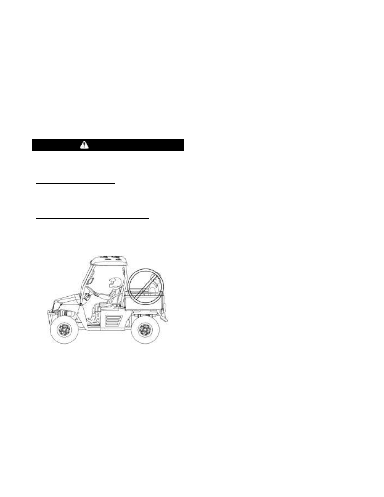
WARNING
POTENTIAL HAZARD
Carrying a passenger in the cargo bed.
WHAT CAN HAPPEN
The passenger could fall or be struck
by objects in the cargo bed.
HOW TO AVOID THE HAZARD
Never carry a passenger in the cargo
bed. The cargo bed is designed to
carry cargo only.
The total weight of operator, passenger,
accessories, cargo, trailer tongue weight,
and the vehicle itself must not exceed 914Kg
(1848 lb). (See “Loading” on page 6-11.)
Carrying a passenger and cargo can affect
vehicle handling.
Page 80
7-3
WARNING
POTENTIAL HAZARD
Overloading this vehicle or carrying or
towing cargo improperly.
WHAT CAN HAPPEN
Could cause changes in vehicle
handling which could lead to an
accident.
HOW TO AVOID THE HAZARD
Never exceed the stated load capacity
for this vehicle.
Cargo should be properly distributed
and securely attached.
Reduce speed when carrying cargo or
pulling a trailer. Allow greater
distance for braking.
Always follow the instructions in your
Owner’s Manual for carrying cargo or
pulling a trailer.
The driver and passenger must always wear
a seat belt and an approved motorcycle
helmet. Also wear eye protection and
protective clothing, including over-the-ankle
boots, gloves, a long-sleeved shirt or jacket,
and long pants. Keep hands and feet inside
the vehicle at all times.
Page 81
7-4
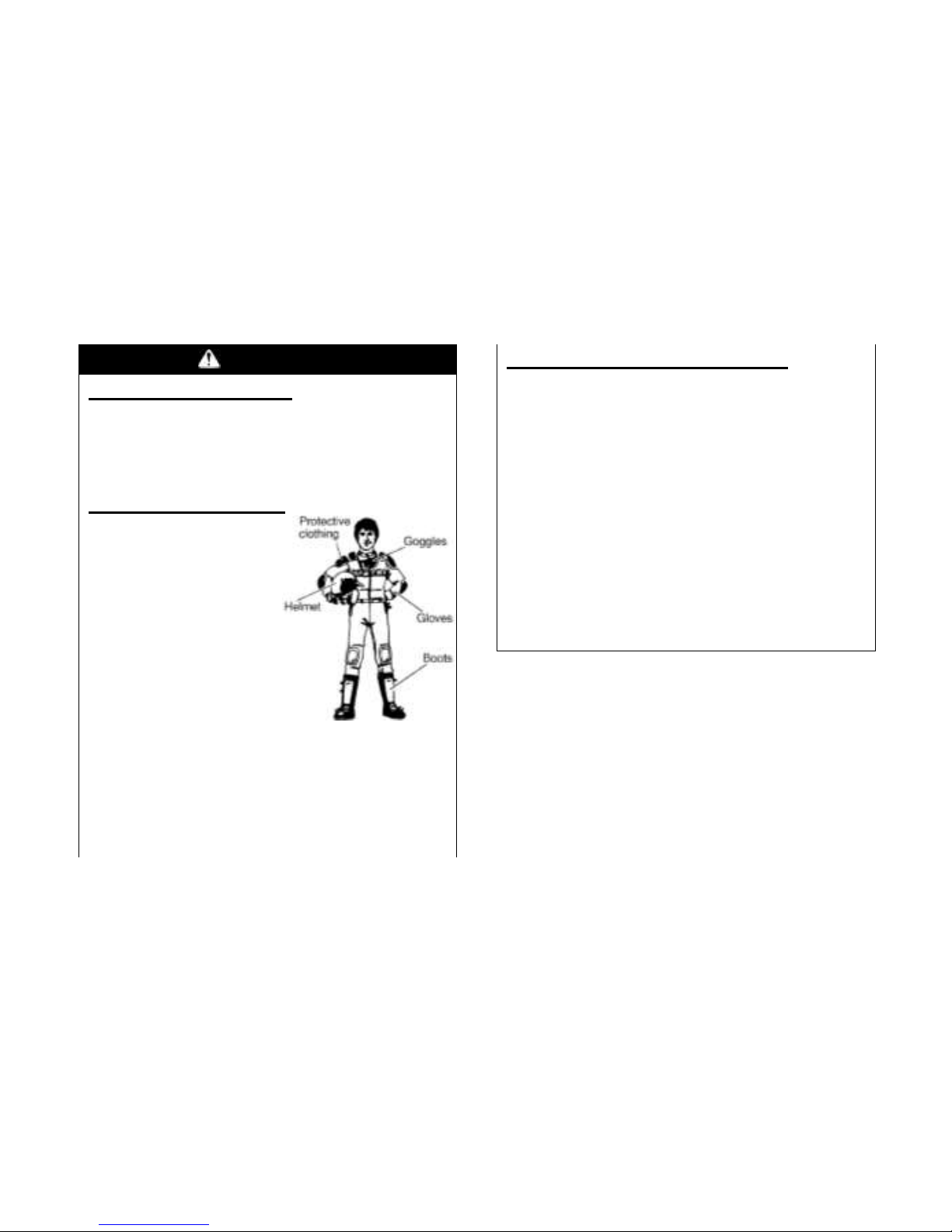
WARNING
POTENTIAL HAZARD
Operating this vehicle without wearing
an approved motorcycle helmet, eye
protection, and protective clothing.
WHAT CAN HAPPEN
Operating without
an approved
motorcycle helmet
increases your
chances of a
severe head injury
or death in
the event of an accident.
Operating without eye protection can
result in an accident and increases
your chances of a severe injury in the
event of an accident.
HOW TO AVOID THE HAZARD
Always wear an approved motorcycle
helmet that fits properly. You should
also wear:
Eye Protection
(Goggles or Face Shield)
Gloves
Boots
Long-Sleeved Shirt or Jacket
Long Pants
Page 82

7-5
LEARNING TO OPERATE YOUR VEHICLE
You should become familiar with the
performance characteristics of the vehicle in
a large, flat area that is free of obstacles and
other vehicles. Practice control of the
accelerator pedal, brakes, steering, and drive
select lever. Drive first at slow speed and
become comfortable at that speed before
gradually increasing your speed. Become
familiar with the way the vehicle feels in low
and high ranges, first in two-wheel drive
(2WD) and then in four-wheel drive (4WD)
and four-wheel drive with the differential
locked (DIFF. LOCK). Also practice driving
in reverse. Take the time to learn basic
operation before attempting more difficult
maneuvers.
Perform the Pre-Operation Checks on pages
5-1-5-15. Set the parking brake, shift to
neutral, and follow the instructions on page
6-1 to start the engine. Once it has warmed
up and you have turned the choke off, you
are ready to begin driving your vehicle.
With the engine idling, shift the drive select
lever into low or high. Then release the
parking brake. Press the accelerator pedal
slowly and smoothly. The centrifugal clutch
will engage and you will start to accelerate.
Avoid higher speeds until you are thoroughly
familiar with the operation of your vehicle.
When slowing down or stopping, take your
foot off the accelerator pedal and smoothly
press the brake pedal. Improper use of the
brakes can cause the tires to lose traction,
reducing control and increasing the
possibility of an accident.
Page 83
7-6
1CAUTION:
Do not shift from low to high or vice versa
without coming to a complete stop and
waiting for the engine to return to normal idle
speed. Damage to the engine or drive train
may occur.
TURNING YOUR VEHICLE
The vehicle is easier to steer in two-wheel
drive (2WD) than four-wheel drive (4WD).
Steering takes the most effort in 4WD with
the differential locked (DIFF. LOCK).
It is possible for the vehicle to roll over or go
out of control if you attempt sharp,
high-speed turns. You should also be
careful making sharp turns on rough terrain.
Do not attempt to turn around or make abrupt
maneuvers on slope.
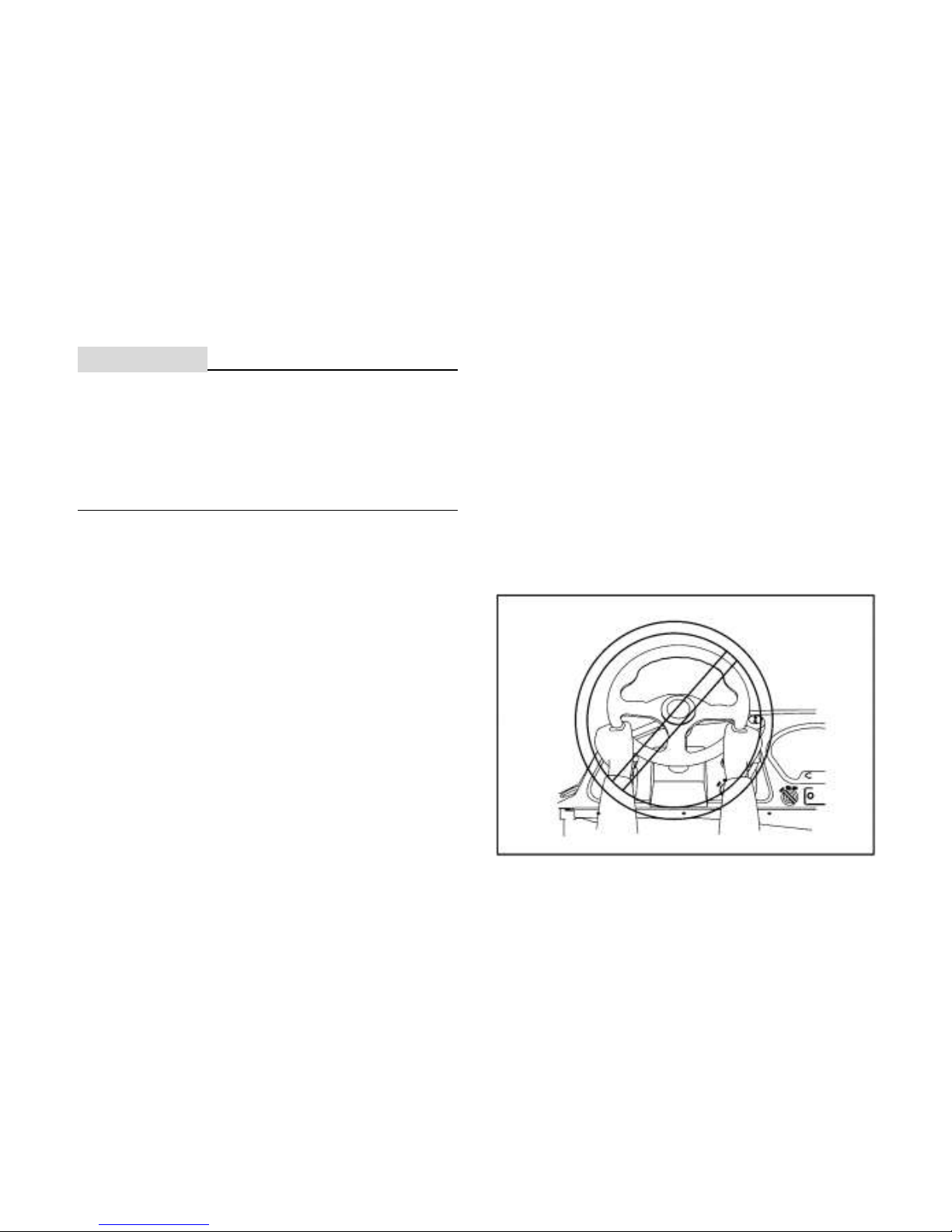
Position your hands on the steering wheel so
that your thumbs and fingers do not wrap
around the wheel. This is particularly
important when driving in rough terrain. The
front wheels will move right and left as they
respond to the terrain, and this movement
will be felt in the steering wheel. A sudden
jolt could wrench the steering wheel around,
and your thumbs or fingers could be injured if
they are in the way of the steering wheel
spokes.
Page 84
7-7
Operating Improperly in Reverse
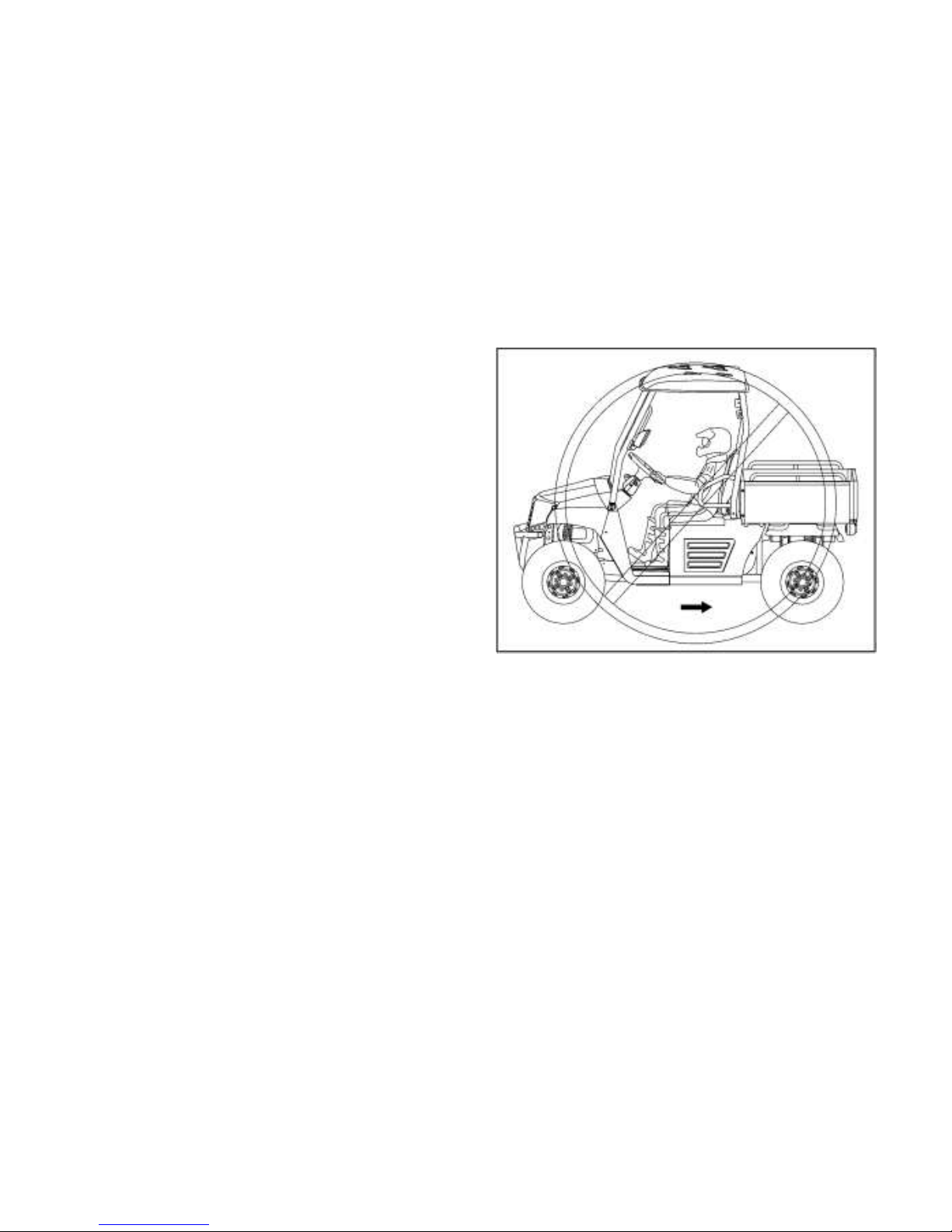
Improperly operating in reverse could result
in a collision with an obstacle or person.
Always follow proper operating procedures 。
Follow these precautions when operating in
reverse:
1. Always check for obstacles or people
behind the vehicle.
2. Apply the throttle lightly. Never open the
throttle suddenly.
3. Back slowly.
4. Apply the brakes lightly for stopping.
5. Avoid making sharp turns.
Before shifting into reverse gear, always
check for obstacles or people behind the
vehicle. When it’s safe to proceed, back
slowly.
Page 85
7-8
BRAKING
Braking ability is affected by the type of
terrain. In most cases, gradually application
of the brakes is more effective than abrupt
braking, particularly on loose surfaces like
gravel. Always allow for greater braking
distance on rough, loose, or slippery
surfaces.
GOING UPHILL
Do not attempt to climb hills until you have
mastered basic maneuvers on flat ground.
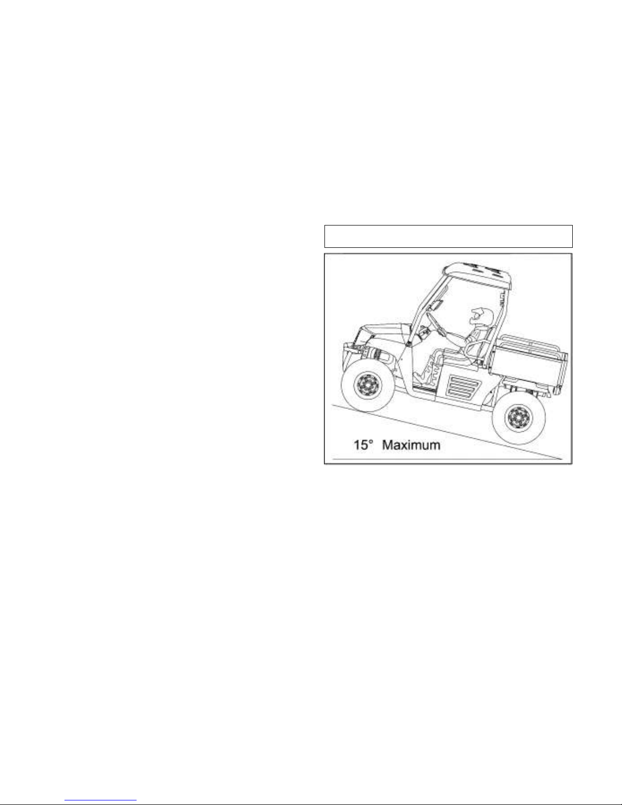
Use proper driving techniques to avoid
overturns on hills and slopes. Drive straight
up hills, and avoid crossing the side of a hill,
which increases your chance of rollover.
Practice first on gentle slopes before
attempting steeper hills. Always check the
terrain carefully before attempting any hill.
Use common sense and remember that
some hills are too steep for you to climb.
Maximum slope angle: 15°
Choose carefully which hills you attempt to
climb. Avoid hills with slippery surfaces or
ones where you will not be able to see far
enough ahead of you.
Page 86
7-9
WARNING
POTENTIAL HAZARD
Operating on excessively steep hills.
WHAT CAN HAPPEN
The vehicle can over turn more easily
on extremely steep hills than on level
surfaces or small hills.
HOW TO AVOID THE HAZARD
Never operate your vehicle on hills too
steep for it or your abilities. Never
operate vehicles on hills steeper than
15°.
Do not drive across the face of a hill.
Go straight up the hill.
Practice on smaller hills before
attempting large hills.
Before climbing the hill, first be sure you are
operating in low range 4WD or, if necessary,
with 4WD Diff. Lock. To climb a hill, you
need traction, momentum, and steady
throttle. Travel fast enough to keep your
momentum going, but not so fast that you
cannot react to changes in the terrain as you
climb. Slow down when you reach the crest
of the hill if you cannot clearly see what is on
the other side. There could be another
person, an obstacle, or a sharp drop off.
If you start to lose traction or momentum
when climbing, and you decide you will be
unable to continue, use the brakes to come
to a stop. Do not attempt to turn the vehicle
around. With your foot on the brake, look
behind you and plan your descent. Shift the
Page 87
7-10
drive select lever in reverse so you can use
the engine brake if necessary to slow your
descent. Release the brake and begin to
coast down the hill. Use engine braking as
much as possible, gently applying the brakes
when necessary.
GOING DOWNHILL
Check the terrain carefully before going
down a hill. When possible, choose a path
that lets you drive your vehicle straight
downhill. Avoid sharp angles that could
allow the vehicle to pitch or roll over.
Carefully choose your path and drive no
faster than you will be able to react to
obstacles that may appear.
WARNING
POTENTIAL HAZARD
Going down a hill improperly.
WHAT CAN HAPPEN
Could cause loss of control or cause
the vehicle to overturn.
HOW TO AVOID THE HAZARD
Always check the terrain carefully
before you start down any hill. Never
go down a hill at high speed. Avoid
going down a hill at an angle that would
cause the vehicle to lean sharply to one
side. Go straight down the hill where
possible.
Page 88

7-11
Before starting down hill, make sure the
vehicle is in low-range 4WD. On most
slopes, this will let you use engine braking to
help you go downhill slowly. Go as slowly
as possible. If you start going too fast,
gently apply the brakes. Avoid sudden
application of the brakes, which could cause
the vehicle to start sliding.
If you are sliding or skidding, try to steer in
the direction the vehicle is sliding to help you
regain control.
If you must turn on the hill to avoid an
obstacle, do so slowly and carefully. If the
vehicle starts to tip, gradually steer in the
downhill direction if there are no obstacles in
your path. As you regain proper balance,
gradually steer again in the direction you
want to go.
CROSSING THROUGH SHALLOW WATER
If you must cross shallow, slow moving water
up to the depth of the vehicle’s floorboards,
choose your path carefully to avoid sharp
drop-offs, large rocks, or slippery surfaces
that could cause the vehicle to overturn.
Never operate through water deeper than 33
cm (13in) or fast flowing water.
Wet brakes may have reduced effectiveness.
After leaving the water, test your brakes. If
necessary, apply the brakes several times to
let friction dry out the linings.
Page 89
7-12
WARNING
POTENTIAL HAZARD
Operating this vehicle through deep or
fast-flowing water.
WHAT CAN HAPPEN
Loss of control, which could result in
an accident including overturn, which
could increase the risk of drowning.
HOW TO AVOID THE HAZARD
Never operate this vehicle in fast
flowing water or in water deeper than
33cm (13in).
Remember that wet brakes may have
reduced stopping ability. Test your
brakes after leaving water. If
necessary, apply brakes several times
to let friction dry out the linings.
1CAUTION:
After riding your vehicle in water, be sure to
drain the trapped water by removing the
check hose at the bottom of the air filter case,
the CVT-belt cooling duct check hose, the
drive select lever box check hose and the
CVT-belt case drain plug. Wash the vehicle
in fresh water if it has been operated in salt
water or muddy conditions.
Page 90

7-13
Vehicle Immersion
CAUTION:
If your vehicle becomes immersed, major
engine damage can result if the machine is
not thoroughly inspected. Take the vehicle to
your dealer before starting the engine.
If it’s impossible to take your vehicle to a
dealer before starting it, follow the steps
outlined below.
1. Move the vehicle to dry land.
2. Check the air box. If water is present, dry
the air box and replace the filter with a
new filter.
3. Remove the spark plugs.
4. Turn the engine over several times.
5. Dry the spark plugs and reinstall them, or
install new plugs.
6. Attempt to start the engine. If necessary,
repeat the drying procedure.
7. Take the vehicle to your dealer for
service as soon as possible, whether you
succeed in starting it or not.
8. If water has been ingested into the CVT,
make sure inspect the hole without water
left inside. If it is muddy water, open the
CVT cap and wash the parts before
reassemble.
9. check the gearshift, release the water
inside. Wash it if it is necessary.
CAUTION:
Make sure all motion parts coated with
grease after wash and reassemble.
Page 91
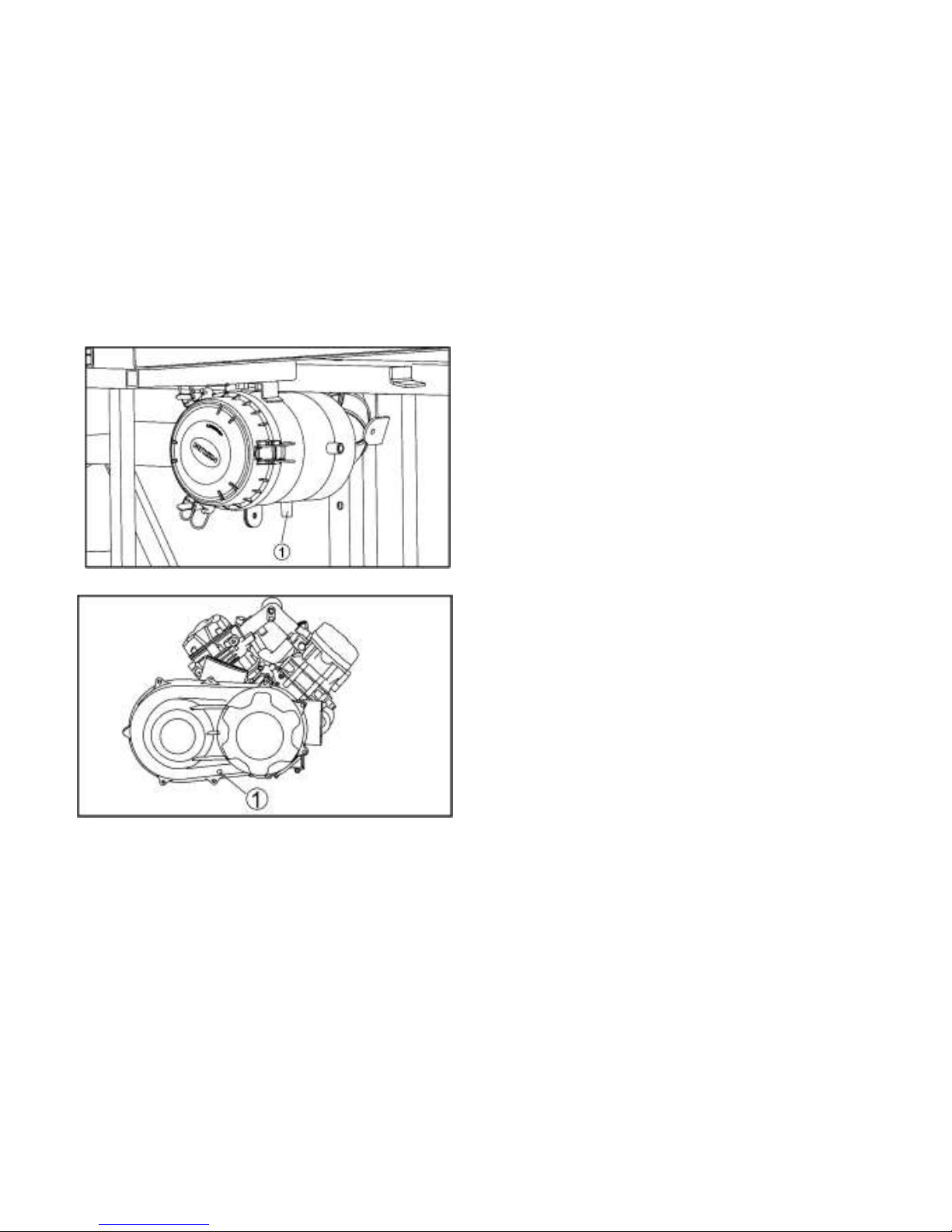
7-14
1.Air filter case check hose
1.CVT Gear Box inspection hole
Front Axle Differential Lock
When driving on rugged or muddy roads,
locking the differential case in the front axle
gearbox will give you the best traction. In
this case, the two front wheels will be driven
at the same rate. It may not be useful to
lock the differential case after you’ve lost
traction, because the skid process has
destroyed the soil structure. Even if you
lock the differential, the front wheels may
continue to slip and will not drive the vehicle
ahead.
Page 92
7-15
Riding Over Rough Terrain
Operating over rough terrain should be done
with caution. Look for obstacles that could
cause damage to the vehicle or could lead to
a rollover accident. Avoid jumping the
vehicle as injury, loss of control, and damage
to the vehicle could occur.
WARNING
POTENTIAL HAZARD
Failure to use extra care when
operating this vehicle on unfamiliar
terrain.
WHAT CAN HAPPEN
You can come upon hidden rocks,
bumps, or holes, without enough time
to react. Could result in the vehicle
overturning or going out of control.
HOW TO AVOID THE HAZARD
Go slowly and be extra careful when
operating on unfamiliar terrain.
Always be alert to changing terrain
conditions when operating the vehicle.
Page 93
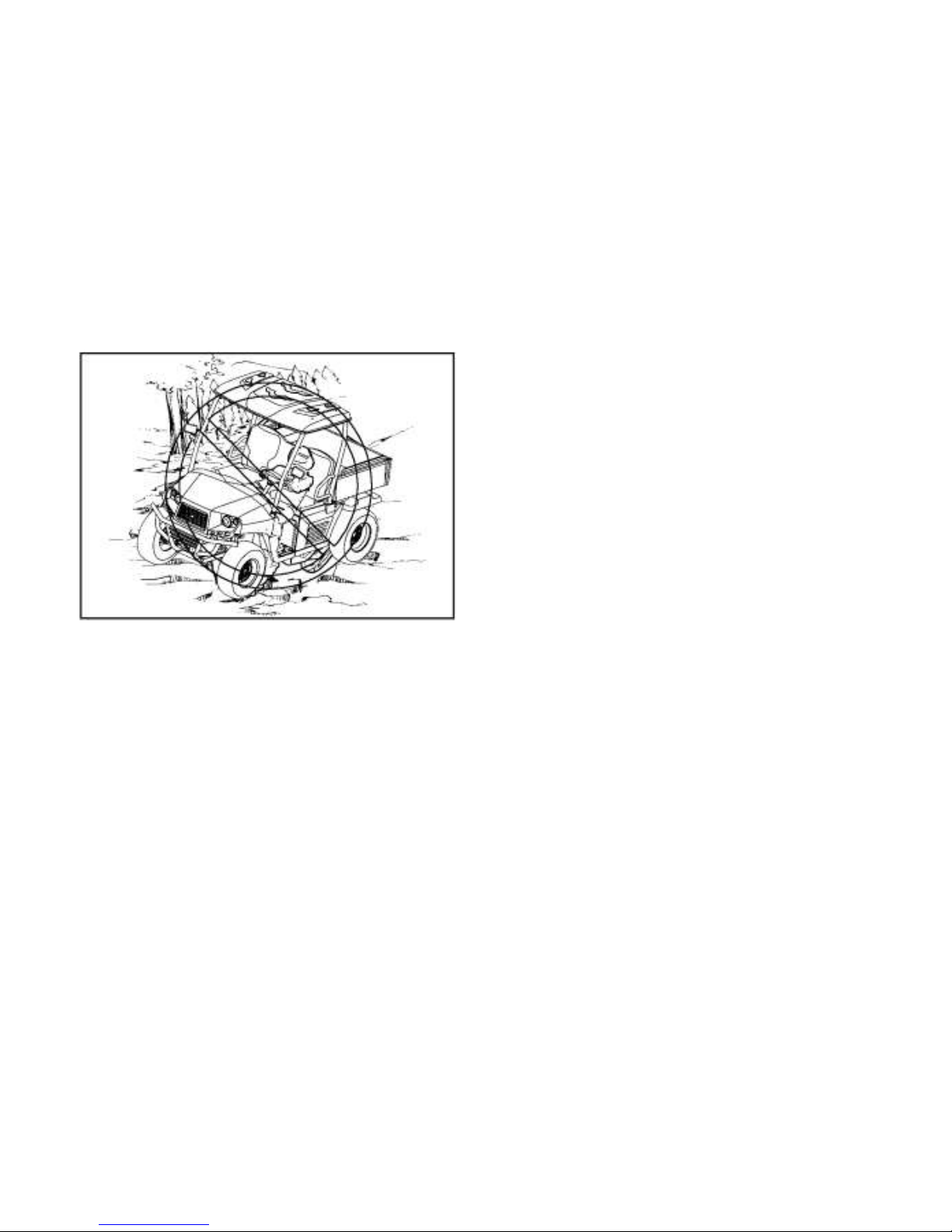
7-16
Riding In Brush Or Wooded Areas
When operating in areas with brush or trees,
watch carefully on both sides and above the
vehicle for obstacles such as branches that
the vehicle might hit, causing an accident, or
for brush that might enter the vehicle as you
pass and strike the driver or passenger.
Never hold onto the enclosure so your hand
is outside the vehicle. Hold only onto the
handgrip inside the enclosure.
Page 94
7-17
Encountering Obstacles On The Trail
If you cannot go around an obstacle such as
a fallen tree trunk or a ditch, stop the vehicle
where it is safe to do so. Set the parking
brake and get out to inspect the area
thoroughly. Look from both your approach
side and the exit side. If you believe you
can continue safely, decide the path that will
allow you to get over the obstacle at as close
to a right angle as possible to minimize
vehicle tipping. Go only fast enough to
maintain your momentum but still give
yourself plenty of time to react to changes in
conditions. If there is any question about
your ability to maneuver safely over the
obstacle, you should turn around, if the
ground is flat and you have the room, or back
up until you find a less difficult path.
WARNING
POTENTIAL HAZARD
Improperly operating over obstacles.
WHAT CAN HAPPEN
Could cause loss of control or a
collision. Could cause the vehicle to
overturn.
HOW TO AVOID THE HAZARD
Before operating in a new area, check
for obstacles.
Use extreme caution when operating
over large obstacles, such as large
rocks or fallen trees.
Page 95

8-1
PERIODIC MAINTENANCE AND
ADJUSTMENT
Periodic inspection, adjustment and lubrication
will keep your vehicle in the safest and most
efficient condition possible. Safety is an
obligation of the vehicle owner. The most
important points of vehicle inspection,
adjustment and lubrication are explained on
the following pages.
The service information included in this
manual is intended to provide you, the owner,
with the necessary information for
completing
your own preventive maintenance
and minor
repairs. The tools provided in the Owner’s
tool kit are sufficient for this purpose, except
that a torque wrench is also necessary to
properly tighten nuts and bolts.
NOTE:
If you do not have a torque wrench available
during a service operation requiring one, take
your vehicle to dealer to check the torque
settings and adjust them as necessary.
Page 96
8-2
WARNING
POTENTIAL HAZARD
Servicing an engine while it is running.
WHAT CAN HAPPEN
Moving parts can catch clothing or parts of the body, causing injury.
Electrical components can cause shocks or can start fires.
HOW TO AVOID THE HAZARD
Turn off the engine when performing
maintenance unless otherwise specified.
Have a dealer perform service if you are
not familiar with vehicle service.
WARNING
POTENTIAL HAZARD
Operating this vehicle with improper
modifications.
WHAT CAN HAPPEN
Improper installation of accessories or
modification of this vehicle may cause
changes in handling which in some
situations could lead to an accident.
HOW TO AVOID THE HAZARD
Never modify this vehicle through
improper installation or use of accessories. All parts and accessories added to
this vehicle should be genuine or equivalent components designed for use on
this vehicle and should be installed and
used according to instructions.
If you have questions, consult an authorized vehicle dealer.
Page 97
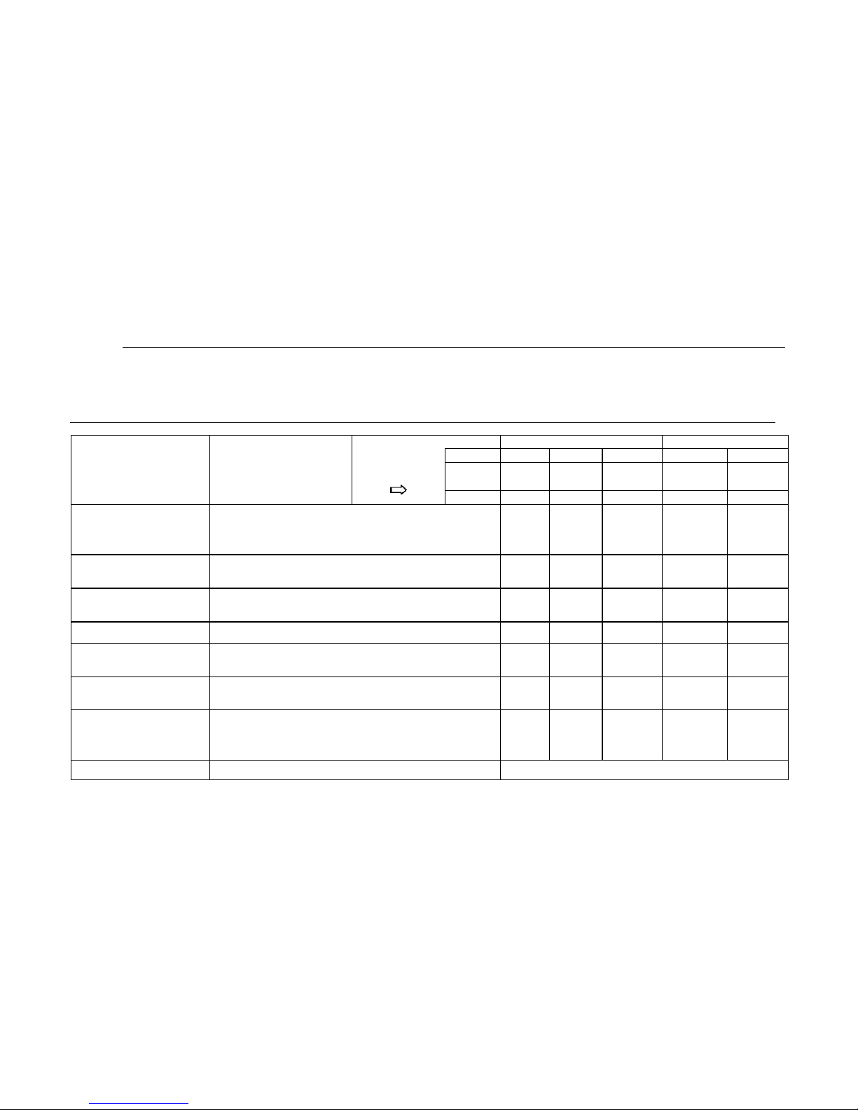
8-3
Periodic Maintenance Chart for the Emission Control System
NOTE:
● For vehicles not equipped with an odometer or hour meter, follow the month maintenance intervals.
● For vehicles equipped with an odometer or an hour meter, follow the km(mi) or hours maintenance intervals. However,
keep in mind that if the vehicle isn’t used for a long period of time, the month maintenance intervals should be followed.
● Items marked with an asterisk should be performed by dealer as they require special tools, data and technical skills.
ITEM
ROUTINE
Whichever
Comes first
INITIAL
EVERY
Month 1 3 6 6
12
Km
(mi)
320
(200)
1,200
(750)
2,400
(1,500)
2,400
(1,500)
4,800
(3,000)
hours
20
75
150
150
300
Spark Plug
● Check condition.
● Adjust gap and clean.
● Replace if necessary.
○ ○ ○ ○ ○
Crankcase Breather
System*
● Check breather hose for cracks or damage.
● Replace if necessary.
○ ○ ○
Valves*
● Check valve clearance.
● Adjust if necessary.
○ ○ ○ ○
Spark Arrester
● Clean.
○ ○ ○
Carburetor*
● Check idle speed/starter operation.
● Adjust if necessary.
○ ○ ○ ○
Fuel Line*
● Check fuel hose for cracks or damage.
● Replace if necessary.
○ ○ ○
Exhaust System*
● Check for leakage.
● Tighten if necessary.
● Replace gasket(s) if necessary.
○ ○ ○
Sensor
● Clean.
Clean for each 500km (312ml)
Page 98
8-4
General Maintenance and Lubrication Chart
ITEM
ROUTINE
Whichever
Comes first
INITIAL
EVERY
Month
1 3 6 6 12
Km
(mi)
320
(200)
1,200
(750)
2,400
(1,500)
2,400
(1,500)
4,800
(3,000)
hours
20
75
150
150
300
Rear Brake*
● Check operation/brake pad wear/fluid leakage/see
NOTE page 8-6.
●
Correct if necessary. Replace pads if worn to the limit.
○ ○ ○
○
○
Cooling System
● Check coolant leakage.
● Repair if necessary.
● Replace coolant every 24 months.
○ ○ ○
○
○
Air Filter Elements
(Engine and Air Intake
Duct)
● Clean.
● Replace if necessary.
Every 20─40 hours
(More often in wet or dusty areas.)
Engine Oil
● Replace (Warm engine before draining.)
○ ○
○ ○ Engine Oil Filter Cartridge
● Replace
○ ○
○
○
Final Gear Oil
● Check oil level. Check oil leakage.
● Replace.
○
○
Differential Gear Oil
Front Brake*
● Check operation/brake pad wear/fluid leakage/see
NOTE page 8-6.
●
Correct if necessary. Replace pads if worn to the limit.
○ ○ ○
○
○
Front and Rear
Suspension*
● Check operation and for leakage.
● Check toe-in/Adjust if necessary.
○
○
CVT-Belt*
● Check operation.
● Check for wear, cracks, or damage.
○
○
○
Accelerator Pedal*
● Check operation and free play.
○ ○ ○
○
○
Wheel Bearings*
● Check bearing assemblies for looseness/damage.
● Repair if damaged.
Wheels*
● Check balance/damage/run out.
● Replace if necessary.
○ ○
○
○
Page 99
8-5
ITEM
ROUTINE
Whichever
Comes first
INITIAL
EVERY
Month
1 3 6 6 12
Km
(mi)
320
(200)
1,200
(750)
2,400
(1,500)
2,400
(1,500)
4,800
(3,000)
hours
20
75
150
150
300
Engine Mount*
● Check for cracks or damage.
● Check bolt tightness.
○ ○ ○
Steering System*
● Check operation and for looseness. Replace if
damaged.
● Check toe-in. Adjust if necessary
○ ○ ○ ○ ○
Front and Rear Axle Boots*
● Check operation.
● Replace if damaged.
○ ○
Drive Shaft Universal Joint*
● Lubricate with lithium-based grease.
○ ○ ○
Rear Upper and Lower
Knuckle Pivots*
● Lubricate with lithium-based grease.
○ ○ ○
Fittings and Fasteners*
● Check all chassis fittings and fasteners.
● Check if necessary.
○ ○ ○ ○ ○
Anti-Roll Bar Bushings*
● Check for cracks or damage.
○ ○ ○
NOTE:
● Recommended brake fluid: DOT4
● Brake fluid replacement.
● When disassembling the master cylinder or caliper, replace the brake fluid. Normally check the brake
fluid level and add fluid as required.
● On the inner parts of the master cylinder and caliper, replace the oil seals every two years.
● Replace the brake hoses every four years, or if cracked or damaged.
Page 100
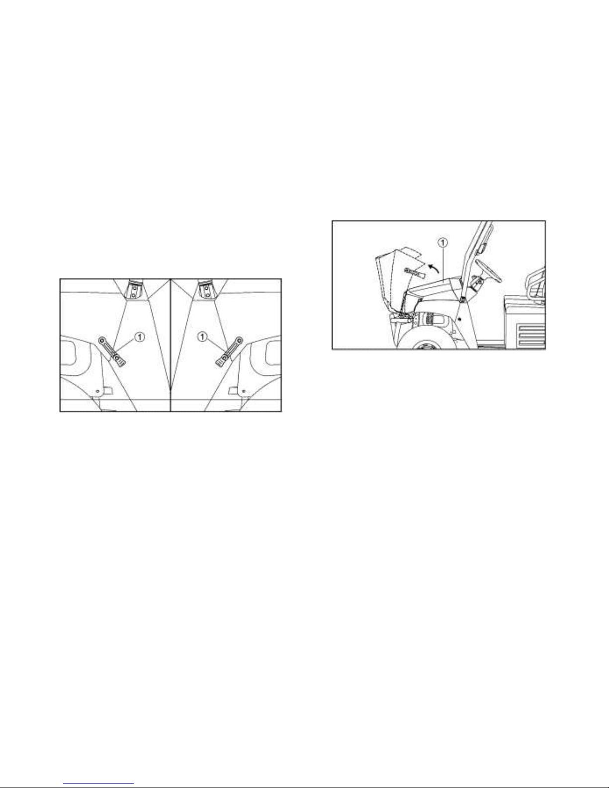
8-6
Hood
To Open
Unhook the hood latches, and then slowly tilt
the hood up until it stops.
1. Latch(×2)
1. Hood
To Close
Lower the hood slowly to its original position,
and then hook the hood latches.
Secure projections ① on the underside of the
hood into slots ② on the back of the
instrument panel. Secure slots ③ on the side
of the hood around projections ④ on the
frame.
 Loading...