

Page 1

The Faroudja
LD100/LD100U Line Doubler
Installation & Operation
Instructions
Page 2

History . . . . . . . . . . . . . . . . . . . . . . . . . . . . . . . . . . . . . . . . . . . . . . . . . . . . 2
Licensees and Awards. . . . . . . . . . . . . . . . . . . . . . . . . . . . . . . . . . . . . . . . 3
System Description . . . . . . . . . . . . . . . . . . . . . . . . . . . . . . . . . . . . . . . . . . 4
Inventory List . . . . . . . . . . . . . . . . . . . . . . . . . . . . . . . . . . . . . . . . . . . . . . . 5
Caution Notes . . . . . . . . . . . . . . . . . . . . . . . . . . . . . . . . . . . . . . . . . . . . . . 5
Technical Highlights . . . . . . . . . . . . . . . . . . . . . . . . . . . . . . . . . . . . . . . . . . 6
Installation Instructions. . . . . . . . . . . . . . . . . . . . . . . . . . . . . . . . . . . . . . . . 8
Rear Panel I/O . . . . . . . . . . . . . . . . . . . . . . . . . . . . . . . . . . . . . . . . . . . 8
Interface . . . . . . . . . . . . . . . . . . . . . . . . . . . . . . . . . . . . . . . . . . . . . . . . 9
Line Doubler Operating Instructions. . . . . . . . . . . . . . . . . . . . . . . . . . . . . 10
Troubleshooting . . . . . . . . . . . . . . . . . . . . . . . . . . . . . . . . . . . . . . . . . . . . 12
Appendix A: Remote Control Operation. . . . . . . . . . . . . . . . . . . . . . . . . . 13
Appendix B: VGA Output . . . . . . . . . . . . . . . . . . . . . . . . . . . . . . . . . . . . . 16
Appendix C: Cable Lengths . . . . . . . . . . . . . . . . . . . . . . . . . . . . . . . . . . . 16
Specifications. . . . . . . . . . . . . . . . . . . . . . . . . . . . . . . . . . . . . . . . . . . . . . 17
Warranty Information . . . . . . . . . . . . . . . . . . . . . . . . . . . . . . . . . . . . . . . . 18
Copyright©1994 by Faroudja Laboratories Inc.
No part of this document may be copied, photocopied, reproduced, translated, or reproduced to any electronic
medium or machine readable form without prior consent, in writing, from Faroudja Laboratories, Inc.
The Faroudja Laboratories LD100 Line Doubler is covered by the following United States patents: 4,030,121,
4,179,705, 4,240,105, 4,262,304, 4,847, 681, 4,864,389, 4,876,596, 4,893,176, 4,916,526, 4,967,271,
4,982,280, 4,989,090, 5,014,119, 5,025,312, 5,159,451, 5,237,414.
All Rights Reserved.
TABLE OF CONTENTS
Page 3

HISTORY
Faroudja Laboratories, located in northern California’s Silicon Valley, was founded in 1971 by Yves
and Isabell Faroudja to develop state-of-the-art of
video processing technology. Over the last 20
years, Faroudja Laboratories and its companion
R&D center, Faroudja Research, have indeed developed hundreds of advanced electronic processes
to improve video enhancement, noise reduction
and NTSC encoding/ decoding technologies. Many
of these processes are used under license by
the world’s leading electronics companies in a
wide range of high performance video products.
Faroudja professional video equipment is also
currently hard at work in hundreds of television
studios. Thus Faroudja technology is utilized and
enjoyed in millions of American homes every day.
Yves Faroudja has devoted his career and his company to the goal of enabling home video systems to
achieve the image quality of 35mm motion pictures.
In pursuit of this goal, Faroudja Labs has made use
of techniques from Faroudja professional video
equipment and incorporated these in the LD100
and LD100U line doublers.
This booklet will provide the reader with a handson look at the LD100, its operation and benefits.
Also supplied is an overview of the proprietary tech-
2
nologies utilized in this extraordinary device and an
explanation of the visual improvements it provides
in home video playback systems.
First, before we discuss the LD100, let’s take a
quick look at the history of the current television
standard. Today’s 525 line TV picture standard was
actually developed in the 1940’s when broadcasts
were only in black and white. Keep in mind that
back then, the transistor had not yet been invented!
In 1953, the National Television Systems Committee
(NTSC) adopted what is still the present method of
color TV broadcasting. It was designed to be fully
compatible with the older technology of black and
white transmission. Unfortunately, this need to maintain compatibility with old technology led to
unavoidable compromises in NTSC picture quality.
Today, thanks to the advent of new thinking and
new technologies realized by industry pioneer Yves
Faroudja, these compromises can be nearly
eliminated. Faroudja’s unique approach focuses
on critical problem areas in the NTSC and PAL
broadcast format. With patented engineering and
design work, Yves and Faroudja Laboratories have
created an exceptional product that brings new levels of visual reality to the enjoyment of discerning
video enthusiasts around the world.
Some Video History and the Faroudja Approach
Page 4

LICENSEES AND AWARDS
1987: SMPTE
DAVID SARNOFF GOLD MEDAL AWARD
for
“Contributing in Optimizing NTSC Performances”
1988: MONITOR AWARD
for
“Excellence in Engineering
NTSC Encoders and Decoders”
1989: BM/E AWARD
for
“Excellence in Engineering”
1991: Technology Executive of the Year
from Cable TV Business
1991: EMMY
from The National Academy
of Television Arts and Sciences
for
“Techniques for Minimization of NTSC Artifacts
Through Advanced Encoding Techniques”
1992: VIDEO GRAND PRIX AWARD
Audio/Video International
LD100 Line Doubler “Advanced Technology Award”
1993: VIDEO MAGAZINE
Video Visionary
LD100 Line Doubler “10 Best Products”
3
Licensees Around the World
Faroudja’s inventive approach to improving the quality of video imaging has caught the eye of some of
the world’s greatest high technology companies.
The following list represents those that have recognized the value of Faroudja’s solutions to imaging
problems and pay for the opportunity to incorporate
this technology in their advanced video products (as
of December 1993):
Canon Microtime
Conrac Mitsubishi
General Instrument NAC
Grass Valley NEC
Hitachi Sanyo
Ikegami Sharp
JVC Sony
Matsushita (Panasonic) Toshiba
Awards and Achievements
In just the last four years, Yves Faroudja and
Faroudja Labs have garnered worldwide recognition
and a number of industry awards. These honors are
notable for several reasons. They are in response to
the significant impact that Faroudja’s technology has
made on the serious improvement of video quality.
They are also a reflection of his long term dedication
to continually improving and optimizing the performance of the NTSC video format.
In chronological order, these awards and their specific focus are listed including an EMMY in 1991 for
minimizing artifacts in the NTSC broadcast encoding process.
Page 5

The Faroudja System LD100 digital scan converter
is a precision video instrument used to convert
NTSC Composite, Y/C, or 525 line RGB or
Component interlaced signals into 525 line progressive outputs. Using the LD100 digital scan converter
will produce pictures with more details, remove
unwanted picture artifacts and, when used with projection systems, produce pictures of exceptional
quality, giving a “cinema-like” feeling.
Front panel features include Power, Input Select
(Video, Y/C, RGB and Component), Brightness,
Contrast, Color, Auto-Tint, Noise Reduction, Detail,
AGC and Freeze. Input switch settings are memorized when the power is removed from the unit. This
allows the LD100 to be interfaced into a system
without the need to select the input when the system is powered up. During power up, the AGC
switch is selected in the On mode with the Freeze
switch selected OFF. The remaining controls may be
left in factory preset or manually set by pulling out
and rotating the control until the desired level is
established.
Inputs to the LD100 include: Composite Video, Y/C
(S-VHS), RGB and Component (Y,R-Y,B-Y). The
Video input may be connected by either a BNC connection or a video RCA type connection. These
inputs are looped internally so that the signal may
be used by other devices. A selectable 75 Ohm terminator switch is provided and should be in the ON
position if the input loop is not used. The Y/C input
uses a standard 4 pin S-VHS connector. This input
is not available for a looped operation and is terminated internally. The RGB and Component inputs
use BNC connectors. As with the video input, these
inputs are loopable to other devices. Selectable 75
Ohm terminations are provided. If the looped inputs
are used, these cables should be kept short, (under
6' in length) or a video distribution amplifier should
be used. This allows the LD100 to keep the highest
signal bandwidth possible without having the high
frequency being attenuated in a long cable.
Output from the LD100 is provided on six BNC connectors as well as one 15 pin ‘D’ VGA connector.
The BNC outputs provided are Red, Green, Blue,
Horizontal Sync, Vertical Sync and Composite Sync.
Interface to monitors/projectors can be of a 4 or 5
wire connection. Note: 4 wire, meaning Red, Green,
Blue and Composite Sync or 5 wire, meaning Red,
Green, Blue, Horizontal Sync and Vertical Sync.
There is no sync present on the Green output. The
LD100 is capable of driving a monitor/projector
using the BNC outputs as well as a VGA monitor
using the 15 pin ‘D’ connector, at the same time.
The LD100 features a remote control interface that
will allow control of all line doubler functions. The
remote control uses a 25 pin female ‘D’ connector
located on the rear panel. See appendix A for further information.
4
SYSTEM DESCRIPTION
Page 6

Circuit Description
Figure 1 is a block diagram of the LD100 showing
signal flow and the location of front panel controls
and switches. Composite Video and Y/C (S-VHS)
inputs are connected to the units decoder with AGC
control and converted to Y, R-Y and B-Y signals.
The Y, (Luminance) output from the decoder enters
the input switcher while the R-Y and B-Y signal
enter the Chroma Enhancement block where the
Tint phase can be adjusted when selected in the
manual mode. The RGB input signals are transcoded to Y, R-Y, and B-Y signals and fed to the
input switcher. Component signals are fed directly
to the input switcher.
The input switcher then selects the correct function
and outputs the Y signal to the Luminance Line
Doubler block. The Luminance Line Doubler block
contains the Brightness, Contrast and Freeze controls while the R-Y and B-Y signals enter the
Chroma Line Doubling block where the color level
can be controlled along with the Freeze controls.
The Line Doubled Luminance signal now enters the
Luminance Detail and Noise Reduction block where
the functions of Noise Reduction and Detail Level
are controlled.
The Luminance signal from the Luminance Detail
and Noise Reduction block along with the R-Y and
B-Y signals from the Chroma Line Doubling block
feed the output transcoder and are converted to
RGB signals. These RGB signals are buffered and
then sent to the rear panel outputs to both the BNC
and VGA interface connectors.
When using the RGB or Component inputs, Sync is
derived from the G or Y input signals unless sync is
provided to the Composite Sync input. The
Composite Sync input will override the sync from
the G or Y inputs. The sync signal then feeds the
LD100 systems clock generator and is used as a
reference to generate Horizontal Sync, Vertical
Sync, Composite Sync.
Inventory List
1 LD100 Digital Scan Converter
1 Installation/Operation Manual
1Warranty Card
1 Power Cord
2 Rack Mount Ears
1 Rack Mount Screw Kit
5
SYSTEM DESCRIPTION
Caution Notes
Do not connect the LD100 to a Monitor/
Projector not capable of the correct scan
rates. (31.5KHz)
High Voltages are present inside. Opening
the unit will void all warranties.
No user serviceable parts inside.
Page 7
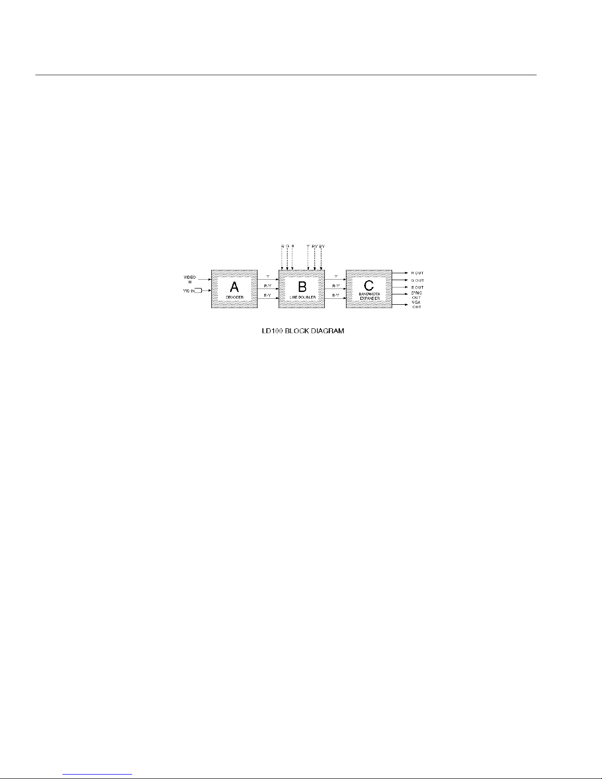
LD100 TECHNICAL HIGHLIGHTS – The LD100 is far more than simply a “line doubler”. It is a truly unique product in the
world of high performance video. The LD100 is actually a complex image processor that consists of three distinct
components – all utilizing patented Faroudja technologies and engineered into one chassis; the SuperNTSC
decoder , the Faroudja proprietary line doubler, and Faroudja’s innovative bandwidth expansion circuit that
allows for the sharpening of image details. Line doubling by itself is simple and inexpensive to achieve. But simply
doubling the lines of information is worse than doing nothing at all because the visual result is a picture of lesser quality. To
achieve film-like quality, a great deal more is required than just doubling the lines. The block diagram below provides a simple view of Faroudja’s multi-faceted solution for perfect pictures. The technical and visual benefits of each of these special
circuits are explained more fully below.
6
SECTION A – The LD100 SuperNTSC Decoder: Eliminates COLOR BLURRING – The engineers of the 1940’s
(and the 1950’s, before and during the development of
color broadcasting), had no idea that video images would
one day be blown up as large as they are today. They
therefore designed the color section of the NTSC standard
with severe bandwidth restrictions. This causes colors in
various video images to “blur” and “smear”. These effects
are further aggravated by storage media, such as VHS
tapes, that further degrade the chroma or color signal. e.g.
– note how deep reds smear on VHS tape images.
The Faroudja LD100 utilizes proprietary circuitry to recreate and further correct color details. Technically, this is
accomplished by making use of the sharper black and
white transitions to develop a correction signal that is then
used to sharpen the color transitions. The result is colors
that are restored with sharp details and video images that
retain their original crisp look.
RAINBOW PATTERNS – When you notice the fine detail
of a striped referees shirt rippling with colored rainbows as
the camera pans by, you’ve seen video cross-color interference.
This annoying artifact is caused by imperfect separation of
the color (chroma), and black and white (luminance) signals by the color decoder circuitry. Simple techniques
used commonly to separate the two signals can be effective most of the time, but occasionally are fooled by finer
pitch detail areas like the referees shirt. The decoder in
the LD100 has patented digital adaptive comb filter circuitry that eliminates decoding errors of this type and
enables the reproduction of sharper, cleaner color images.
DOT CRAWL and HANGING DOTS – This phenomena is
easily seen with large, highly colored, stationary graphics
like titles and credits. Dot crawl is a rapid upwards movement of colored dots on sharp vertical transitions. Hanging
dots lie underneath all the colored horizontal transitions.
Both of these color aberrations are artifacts that appear
due to an imperfect color decoding process. The LD100
has two separate and patented correction circuits that
work to eliminate both of these distortions. The impact is
color transitions that are clear, sharp and natural.
SECTION B – THE LD100 Patented Line Doubler: eliminates VISIBLE SCAN LINES – The secret of the LD100’s
uncanny ability to double the lines of information without
adding digital artifacts is in its unique ability to detect
motion and interpolate correctly to “fill in the blank lines”.
The Faroudja LD100 does this better than any other line
doubler thanks to its proprietary, patented circuitry. It is
the only line doubler in existence that can detect the difference between a film image that has been transferred to
video or video image that emanates from a video camera.
After detecting the image type, the LD100 adjusts its
algorithm to compensate accordingly.
This is critical because today’s home theaters are primarily
used to show films that were transferred to video whether
on tape, laserdisc or off the air (virtually all prime time programs are film transferred to video). The inability of other
line doublers to detect motion correctly is what causes
most of them to be unwatchable due to digital artifacts.
The LD100 offers sharper, uniquely clean, artifact-free
film-like images without visible scanning lines.
Historically speaking again, electrical engineers back in
the 1940’s knew the resolution of a picture tube depends
TECHNICAL HIGHLIGHTS
Page 8
7
on two different mechanisms. Horizontal resolution is a
function of bandwidth (frequency response) of the circuitry
while vertical resolution is a function of the scanning frequency (the number of scan lines in each picture). Given
these mechanisms and the average size picture tube
being 8-10”, they designed the 525 line broadcast standard so that viewers would not see the scan lines when
watching TV. They had no idea that someday people
would be projecting home theater video images with diagonal screen sizes of 10’ and more.
Based on those NTSC parameters, using a 10 ft. diagonal
screen, would require the viewer to be located more than
45 ft. from the screen to see the picture as it was intended, without scan lines! Unfortunately, today’s large screen
installations have scan lines that are quite visible, especially with some of the latest high resolution monitors and
projection televisions. The LD100 eliminates this problem
by scan doubling, or digitally doubling the 525 lines to
become 1050 lines. The result is the elimination of visible
scan lines. The image produced by the LD100 is clearer,
continuous and virtually film-like.
SECTION C – The LD100 Bandwidth Expansion Circuitry:
SHARPENING OF THE IMAGE DETAILS – There is a
major limitation with most contemporary NTSC program
sources — lack of frequency response. The best video
sources such as satellite dish reception and laserdiscs
can provide acceptable resolution (400 plus lines of horizontal resolution). Other more common sources however,
such as VHS tapes (230 lines), are clearly deficient. The
problem is compounded when one doubles the scan lines
and performs other signal processing. The lack of high
frequency detail becomes very obvious with almost all
sources. The resultant picture is free of scan lines but dull,
with a serious loss of definition. The solution is to expand
the high frequencies without producing annoying and picture degrading artifacts.
The bandwith expansion circuitry in the LD100 is exceptionally sophisticated, using Faroudja’s double differentiation techniques to sharpen the edges of both horizontal
and vertical details. The result is a sharply detailed line
doubled image that appears crisp and three dimensional
with no visible negative side-effects. This process can
effectively double the bandwidth and therefore the resolution of the incoming signal.
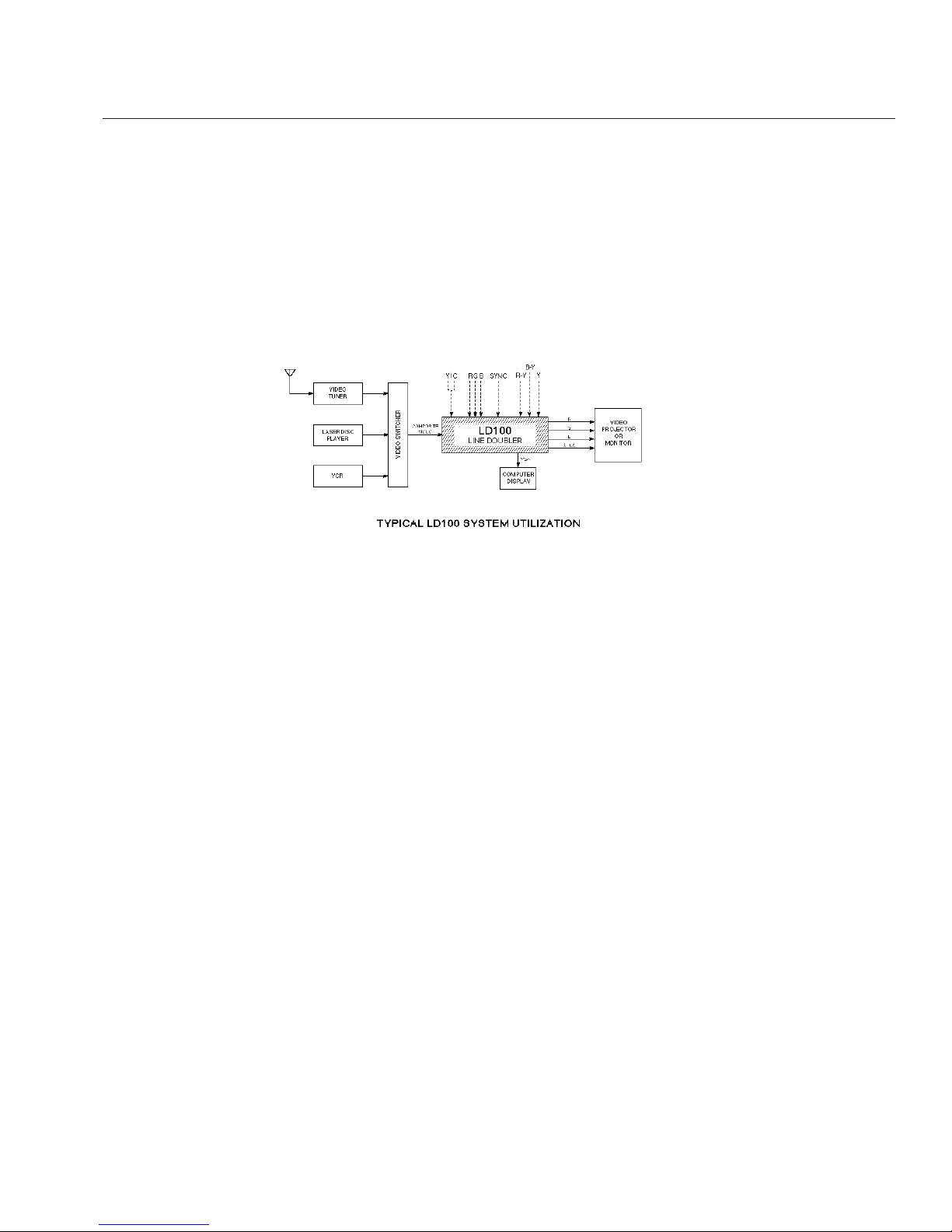
FAROUDJA LD100 APPLICATIONS – While the technical accomplishments of the LD100 represent years of
intense research and development, its use is straightforward and direct. The block diagram (above), illustrates a
typical home theater system configuration and shows how
the LD100 would be inserted in the signal path. Many
entertainment sources benefit greatly by the LD100’s
unique attributes; laserdisc, VHS video, S-VHS video,
cable TV, broadcast TV, etc. The LD100 has proven to be
an invaluable tool in other presentation disciplines where
image quality is important – computer data displays, professional installations in boardrooms and media rooms,
military installations, government agencies and academic
uses in schools and colleges. From the quality of its individual parts to its state-of-the-art patented circuitry, the
LD100 is truly in a class by itself. There is simply no finer
video processor available . . . at any price!
NOTE: The LD100 (NTSC only version) operates properly
with 50Hz 625 line component or RGB sources.
Page 9
Unpacking
Remove the LD100/LD100U from the shipping
container and examine it for any signs of shipping
damage or missing items, (check inventory list on
page 5).
All shipping materials should be saved if the unit
is to be moved or should need to be returned for
service or repair.
Installation
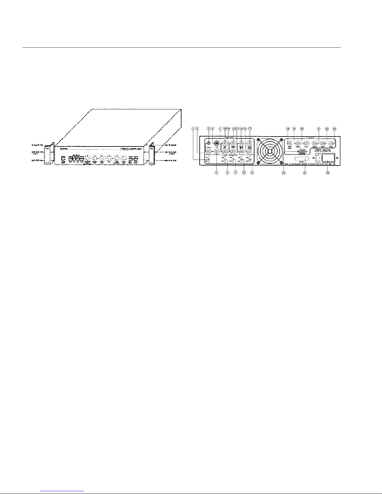
The LD100/LD100U is designed to be placed on the
table or rack mounted. If the rack mounting installation kit is to be used, the rack mount ears are
installed by removing the 4 screws retaining the
wood side panels and installing the rack mount ears
using the 3 screws as shown in Figure 2. Remove
the four feet from the unit. When installing the
LD100 in a rack, it will be necessary to support the
LD100/LD100U by using rack support rails supplied
by the rack manufacturer.
Do not support the LD100/LD100U by the rack
mount ears alone!
Ventilation
The LD100/LD100U will require that air flows freely
in both the bottom and top vent holes. Blocking
these holes will greatly reduce the reliability of the
unit and lead to the possibility of overheating.
When the LD100/LD100U is rack mounted, a minimum of 1.25" (1 rack unit height) of free space is to
be provided for both the top and bottom of the unit
to allow for proper cooling. It is also recommended
that the rack be forced air cooled.
Rear Panel I/O
11. Video Termination Switch – Select ON when
not looping the Video signal to other video
devices, (75 Ohm).
12. Video Input (BNC) – Composite Video Input
13. Video Input (RCA) – Composite Video Input
14. Video Input (BNC) – Composite Video Input
Loop
15. Y/C Input (4 Pin) – Y/C, input internally termi-
nated.
16. R/R-Y Termination Switch – Select ON when
not looping the R/V signal to other video
devices, (75 Ohm).
17. R/R-Y Input Loop (BNC) – Red/R-Y Input
18. R/R-Y Input (BNC) – Red/R-Y Input
19. G/Y Termination Switch – Select ON when
not looping the G/Y signal to other video
devices, (75 Ohm).
10. G/Y Input Loop (BNC) – Green/Y Input
11. G/Y Input (BNC) – Green/Y Input
12. B/B-Y Termination Switch – Select ON when
not looping the B/B-Y signal to other video
devices, (75 Ohm).
13. B/B-Y Input Loop (BNC) – Blue/B-Y Input
14. B/B-Y Input (BNC) – Blue/B-Y Input
8
INSTALLATION INSTRUCTIONS
Figure 2 Figure 3
Page 10
15. Sync Termination Switch – Select ON when
15. not looping the Composite Sync signal to
other video devices, (75 Ohm).
16. Sync Input Loop (BNC) – Composite Sync
Input Loop
17. Sync Input (BNC) – Composite Sync Input
18. Red Output (BNC) – Red Output 714mV
19. Green Output (BNC) – Green Output 714mV
20. Blue Output (BNC) – Blue Output 714mV
21. Horiz. Sync Output (BNC) – Horizontal Sync
Output –4Vp-p, 31.5KHz/31.2KHz
22. Vert. Sync Output (BNC) – Vertical Sync
Output –4Vp-p, 59.49Hz/50Hz
23. Sync Output (BNC) – Composite Sync
Output –4Vp-p
24. VGA Interface Output – VGA Standard using
Positive TTL Sync Levels. See appendix B for
pinout information.
25. Remote Control Interface – See appendix A
for interface diagrams.
26. Power Input – 100-250 VAC, 50/60Hz, 60W
Interface
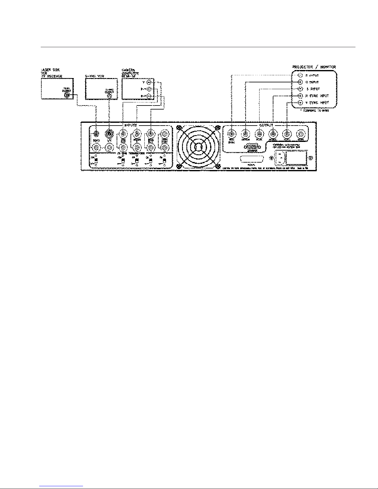
Figure 4 diagrams the installation of the LD100
using inputs from:
1. A composite source such as a Laser Disk Player,
VCR or TV Receiver.
2. A Y/C input such as a S-VHS VCR.
3. An RGB input with sync on green or a
Component input such as a Camera or Beta-SP
recorder with sync on Y. If sync on green or sync
on Y is not available then Sync can be interfaced
using the Composite sync input.
All input with the exception of the Y/C input have
selectable 75 Ohm input termination switches.
These switches are to be in the ON position unless
the LD100 is being used in a looped configuration.
Termination is then located at the last unit in the
loop only.
Note: The diagram shows a 5 wire connection to
the monitor/projector, i.e. Red, Green, Blue,
Horizontal Sync and Vertical Sync. For monitors/
projectors with a 4 wire input, use Red, Green, Blue
and Composite Sync outputs.
The monitor/projector will be terminated at 75 Ohm
either internally or by switches located on the monitor/projector.
9
Figure 4
Page 11
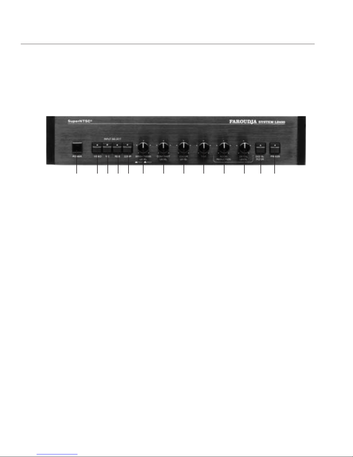
The LD100 Control panel
Selecting a push button control lights the adjacent
LED to indicate activation or selection of that particular function.
1) Power ON/OFF – Press the button and the LED
lights green to indicate POWER ON. When the
LD100 powers up it is automatically set to operate just as it was when it was last turned off. The
Detail Enhancement circuits are automatically
engaged at turn on.
1) Power ON/OFF - OFF – Another push on the
switch and the power is cut off extinguishing the
green LED. The Freeze Circuit is automatically
disengaged, if in use, upon turn off.
INPUT SELECTION SWITCHES (4)
2) Video – refers to any composite NTSC video
input - (e.g. VCR’s, laserdisc players, cable
boxes, etc.) Press to select the Video input.
3) Y/C – Y/C refers to any Super-VHS (S-VHS or
Hi-8) inputs - (e.g. laserdisc players, S-VHS or
Hi-8 video tape recorders, satellite receivers, etc.)
Press to select the Y/C input. Using the Y/C input
on the LD100 allows one to realize all the benefits
of maintaining the separation of the luminance
(picture) and chrominance (color) signal through
the video signal processing chain, thus avoiding
rainbow patterns due to cross color interference.
4) RGB – RGB refers to the incoming video signal
being broken down to the individual red, green
and blue format more typically found in the professional and broadcast area. The most common
4) use of this input is computers (running at 15.75
kHz). Press to select the RGB video input.
5) Component Input – Component Inputs are
more commonly used in the broadcast studio or
post-production environment. The video signal
in its component form (Y, R-Y, B-Y) is carried in
a 3-wire cable with BNC type connectors (e.g.
MII™, D1, Betacam™, Betacam SP™, etc.).
Press to select the Component video input.
PICTURE CONTROLS (4)
The four rotary-style picture controls, BRIGHT-
NESS, CONTRAST, COLOR and TINT, are factory
preset when pushed in. When pulled out they
become active for manual adjustment. Pushing the
knob back in after manual adjustment gives you the
opportunity to compare your setting to the factory
preset(s).
The rotary control format allows for a high degree of
tactile feedback when one is adjusting the picture
functions. Additionally, these controls provide a
wider range of adjustment than those typically found
on monitors and televisions.
In addition, automatic chroma level and phase controls (ACC and APC) are provided. As a consequence, all source-to-source variations in chroma
phase and level are corrected.
When the signal is fed to a monitor through the RGB
inputs the monitor color and tint controls are
typically bypassed. Incorporating the LD100 in such
a system, with its broad range controls, restores
and enhances this control flexibility.
10
LINE DOUBLER OPERATING INSTRUCTIONS
For reasons of clarity, this technical overview has been written specifically for the LD100. This description
applies as well to the LD100U, with the following exceptions:
1. The LD100U accepts PAL and NTSC signals and switches automatically to the proper standard.
2. Tint control is not operational with PAL sources.
1 2 3 4 5 6 7 8 9 10 11 12 13
Page 12

6) Brightness Level – Known as “Set-up” in the
broadcast industry, the BRIGHTNESS control is
used to set up the background black level. Pull
the knob out and turn fully counter clockwise
until the picture goes dark. Then rotate the control clockwise until the black areas in the picture
just begin to go gray. Turn the control back
counter clockwise until the gray just goes to
black. This is the optimum setting.
7) Contrast Level – As the BRIGHTNESS control
sets the background black level, the CONTRAST
control sets the foreground white level. First set
the BRIGHTNESS level as above, then pull out
and rotate the CONTRAST level clockwise, starting at the full counter clockwise position, until the
white areas of the picture are clearly obvious.
8) Color level – With the Color control pressed in,
the LD100 uses its internal AGC, (Automatic
Gain Control) to set the color level. Pull the knob
out and starting from the full counter-clockwise
position, rotate clockwise for increased color saturation. This is a subjective setting, there is no
right or wrong. Simply adjust for the most pleasing color level.
9) Tint – Also known as “Hue” or “Phase”, pull the
knob out to adjust to your personal taste, particularly in flesh tones. Adjusting the tint control
shifts the picture towards the green or red areas
of the color spectrum. Tint is only active in the
video or Y/C input modes. With the control
pressed in, the LD100 is in the Auto-Tint mode.
The Auto-Tint mode is achieved by using internal
phase comparison techniques to automatically
display colors as intended.
IMAGE SHARPNESS CONTROLS (2)
The two rotary-style Image Sharpness controls,
NOISE REDUCTION and DETAIL LEVEL, work
together to sharpen edge transitions for a “punchier” picture. The proprietary bandwith expansion circuitry contained in the LD100 is critical to its spectacular performance. Typical line doublers produce a
flat, soft picture. The LD100’s Image Sharpness circuitry improves the sharp line and edge transitions
making for clearer, more vivid video images. This is
accomplished with the two controls working in tandem, without adding video noise or digital artifacts
which could otherwise degrade the picture.
10) Noise Reduction – After setting the detail level
(11), the noise reduction control is then used to
remove any residual noise that may be added
during the Image Sharpness process.
11) Detail Level – To set the detail level start full
counter clockwise and add detail until the edge
transitions just begin to sharpen.
12) Digital Filter – The Digital Filter eliminates
compression artifacts generated by video
sources transmitted via a digital compressed
path and should not be used with conventional
video sources.
13) Freeze On/Off – Press to capture the current
picture displayed on the screen. Press again to
return to normal, active video. The freeze mode
digitally captures the incoming video signal and
holds it for critical viewing and adjustment. This
feature allows you to optimize the LD100 picture controls on a still, constant image of your
choosing.
MII is a registered trademark of Panasonic. Betacam and Betacam SP are registered trademarks of Sony.
11
Every LD100 is subjected to an intense battery of QC and environmental tests. Then
each unit is re-tested and re-calibrated for optimum performance. The component
parts used in the LD100 are the finest available, ensuring long term consistent performance and reliability. This unique, quality oriented “Faroudja touch” can also
be seen in the design of many of the LD100’s controls and features.
Page 13

Problem Solution
No power light Unit not turned on
Unit not plugged in
Fuse blown
No power at plug
No picture Video source not selected
No video source connected or operating
Projector/Monitor not turned on
Projector/Monitor not connected correctly
Bad video cable
Unit in freeze mode
Check brightness and contrast levels
Colors bleeding Check LD100 termination
Check projector/monitor termination
Contrast set too high
Color set too high
Picture not stable Check interface cables
Sync cables are swapped or not connected
Input source not selected correctly
Check input terminations
Set Sync to STD.
Projector Fast/Slow Horizontal time constant. Should be set to fast.
Incorrect colors Tint in manual mode
Defective output cable
RGB cables are swapped
Check projector/monitor termination
Input source not selected correctly
No burst on input
RGB or Y,R-Y, B-Y Inputs not terminated.
Picture washed out Composite input not terminated
NOTE: To make sure that an input source is not the cause of a problem for a composite source, turn the ter-
mination switch off and connect a composite monitor to the composite input Loop input. For a R,G,B input
source, turn the three termination switches off and connect a R,G,B monitor to the R,G,B input Loop input.
To make sure that a projector is not the cause of a problem, connect a VGA monitor to the 15pin VGA output
connector and check the display to see if it is correct and if the projector is the problem. If the monitor display
shows the same problem as the projector display, then the line doubler has a problem and you should contact
our Technical Support Department.
12
TROUBLESHOOTING
Page 14
Overview
Remote control of the LD100 / LD100U Line
Doubler is provided by an RS-232 serial interface
connector located on the rear panel of the unit. A
external controller such as a computer or integrated
system controller with an RS-232 interface may be
used to control all user accessible functions of the
Line Doubler.
RS-232 controllable functions include: Video, Y/C
(S-VHS), RGB, Component (YUV), Brightness,
Contrast, Color, Tint, Noise Reduction, Detail Level,
Auto-Tint, Digital Filter On/Off, Freeze On/Off, Echo
On/Off, Help, Status and Return to Factory Preset.
Communication Settings
Communication with the LD100 Line Doubler is
accomplished by setting the following conditions:
9600, No Parity, 8 Data Bits and 1 Stop Bit. The factory BUAD rate is set at 9600, but rates of 1200,
2400 and 4800 are also available.
Baud Rate Selection
To change the RS-232 BAUD rate, remove the top
cover of the LD100 Line Doubler. A 4 switch Dip
switch is located on the front panel. Set the switches from the table shown below. If the BAUD rate is
changed, the LD100 MUST be powered off and
then on for the new BAUD rate to take effect.
DIP Switch Settings
Rate 1234
1200 ON ON ON ON
2400 OFF ON ON ON
4800 ON OFF ON ON
*9600 OFF OFF ON ON
* = Factory Preset
INSTALLATION
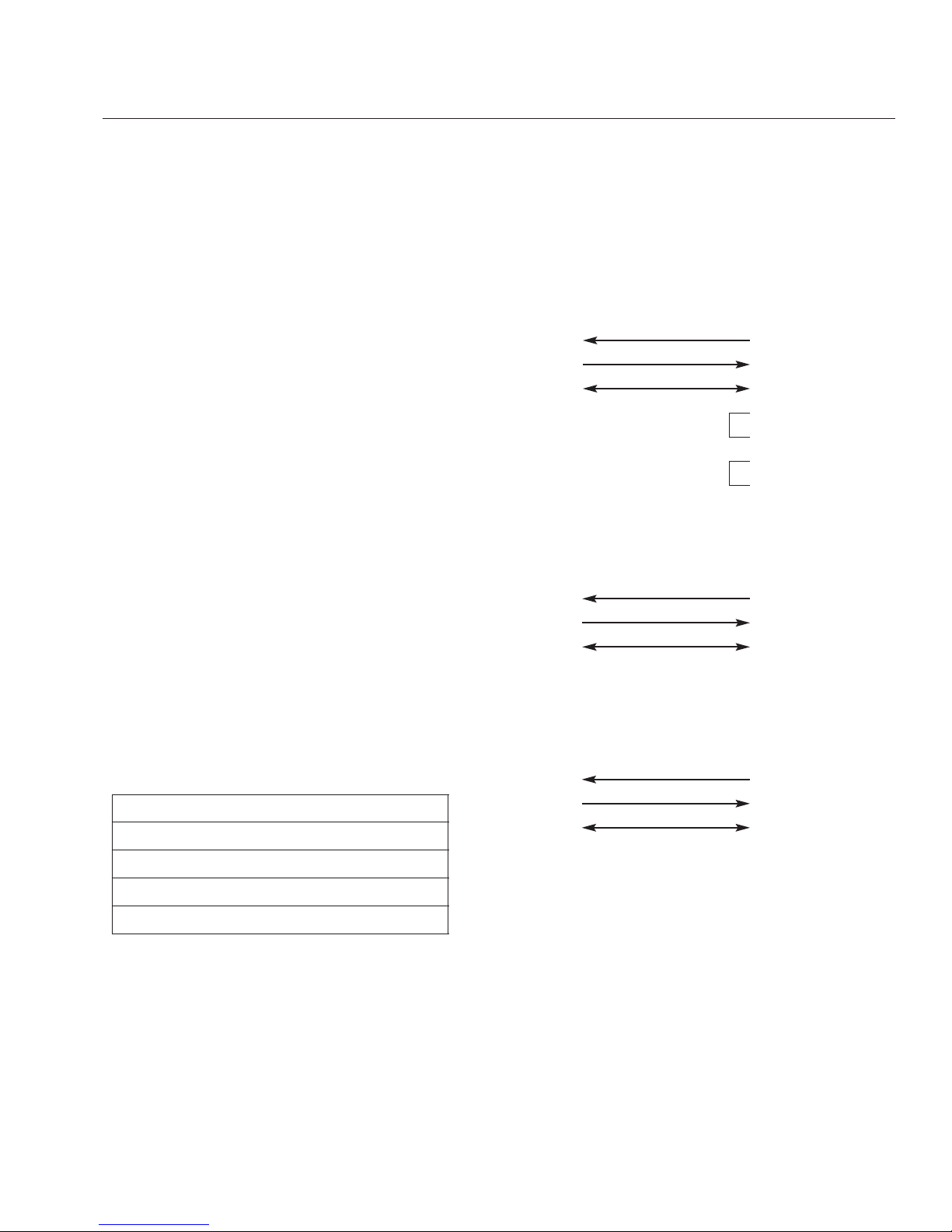
Interface to the LD100 Line Doubler is done by
using a 3 wire interface. Interface schematics for the
IBM-PC™, AMX™ and CRESTRON™ controllers
are shown to the right.
CABLE SPECIFICATION: Computer Interface
LD100/LD100U DATA TERMINAL or
Line Doubler IBM PC
DB25 (MALE) DB25 (FEMALE)
RxD 2 20 TxD
TxD 3 30 RxD
GROUND 7 70 GROUND
40 RTS
50 CTS
60 DSR
20 DTR
CABLE SPECIFICATION: AMX AXC-232 Interface
LD100/LD100U AMX AXC-232
Line Doubler INTERFACE
DB25 (MALE)
RxD 2 3 TxD
TxD 3 2 RxD
GROUND 7 1 GROUND
CABLE SPECIFICATION:
CRESTRON CNCOMH-2/CNMS Interface
LD100/LD100U CRESTON CNCOMH-2
Line Doubler INTERFACE
DB25 (MALE)
RxD 2 3 TxD
TxD 3 2 RxD
GROUND 7 5 GROUND
13
APPENDIX A
LD100/LD100U Remote Control Operation
Page 15

Command Line
The LD100 is programmed by means of a
“Command Line”, which is an ASCII string of up to
255 characters that contains one or more individual
instructions to the LD100. The Command Line
offers the best compromise between manual operation via a data terminal and automatic control via a
controller.
Command Line Entry
A Command Line can be entered in either upper or
lower case by means of a data terminal or other
controller. The Echo Mode determines the response
of the LD100 to the incoming data stream. If the
Echo Mode is ON (E1 command), the entered characters are echoed back to the host, and any message are sent in its entirety. IF Echo Mode is OFF
(E0 command), no characters are sent to host.
Command Syntax
Commands consist of a header followed by a keyword followed by additional parameters if needed.
The header is used to identify the product, in the
case the header is: LD100, . Keywords are single
characters followed by integers (if needed). All commands must be separated by a comma ‘,’. White
spaces are ignored and may be used. All commands strings are terminated by a CARRIAGE
RETURN (0x0d). Commands may in entered in any
order as the user see fit.
Commands
Source Input Select Commands:
V or v Select Video Input Mode
This command is a single character
command.
Y or y Select Y/C Input Mode
This command is a single character
command.
R or r Select RGB Input Mode
This command is a single character
command.
X or x Select Component (YUV) Mode
This command is a single character
command.
Variable Adjustment Commands:
B or b Adjust Brightness Level
This command is follow by an integer
between 0(minimum) and 255(maximum).
Example B1 or B12 or B123, ect.
C or c Adjust Contrast Level
This command is follow by an integer
between 0(minimum) and 255(maximum).
Example C1 or C12 or C123, ect.
K or k Adjust Color Level
This command is follow by an integer
between 0(minimum) and 255(maximum).
Example K1 or K12 or K123, ect.
T or t Adjust Tint Phase
This command is follow by an integer
between 1(minimum) and 255(maximum).
If the command T0 is entered, the AutoTint mode is active where as numbers
from 1 to 255 are used, the Auto-Tint
Function is bypassed. Example T1 or T12
or T123, ect.
N or n Adjust Noise Reduction Level
This command is follow by an integer
between 0(minimum) and 255(maximum).
Example N1 or N12 or N123, ect.
D or d Adjust Detail Level
This command is follow by an integer
between 0(minimum) and 255(maximum).
Example D1 or D12 or D123, ect.
Switch Commands:
A or a Digital Filter On / Off
This command is followed by an integer of
0 for off and 1 for on.
F or f Freeze Mode On / Off
This command is followed by an integer of
0 for off and 1 for on.
Other Commands:
E or e Echo Function
This command is followed by an integer of
0 for off and 1 for on.
P or p This command is a single character com-
mand. This will return the LD100 to it’s
factory preset condition.
14
APPENDIX A
Programming the LD100
Page 16

ST or st This command will return a string showing
the current settings of the LD100.
Example:
HELP or help This command will return a list of
commands used for the LD100
Line Doubler.
LD100 Local / Remote Operation
The LD100 stores all of it’s settings in a Non-volatile
ram and will return to the last known settings when
the unit is power up. The only exception is the
Freeze function. The Freeze function will be set off
during the power up cycle.
When a command is received via the RS-232, only
those functions are placed in the remote mode. If a
pot function is set via the remote, it can be returned
back to local mode by adjusting that function on the
front panel. This is accomplished by creating a window around that function when in remote mode. If
that function is turned beyond the window setpoint,
that function is returned to local mode and becomes
active again.
Command String Examples:
Commands can be as simple as:
LD100,B150(CR)
to complex as
LD100,D240,N20,C150,B102,V,T0,A1,F0(CR)
Note (CR) = Carriage Return (OxOd) or ASCII 13
15
APPENDIX A
LD100:B###,C###,K###,T###,N###,D###,V,T1,A1,F0
(Y)
(R) Freeze
(X) Digital Filter
Auto-Tint
Input Select
Detail Level
Noise Level
Tint Level
Color Level
Contrast Level
Brightness Level
Header
Page 17
Cable Lengths and Distribution Amplifiers
To aid in achieving the bet results from your installation, we suggest the following minimum standards
for cable runs when an LD100 is used.
To preserve the video quality of the LD100, the
signal path should be no more than –3db down at
25 MHz through a 75 ohm cable. Any distribution
amplifier should have a bandwidth no less than
–3db down at 25 MHz.
The following cable lengths are the maximum recommended continuous lengths of 75 ohm coax
cable with BNC connectors on each end as well as
15 pin VGA cable (when using the VGA output).
Cable Type Maximum Length
Mini BNC cables, 75 ohm 100 Feet
1.15nS/Foot propagation
RG-59/U type cable, 75 ohm 150 Feet
75 ohm precision video cable 200 Feet
Belden 8281
15 pin, high resolution VGA cables 25 Feet
utilizing individual high resolution
mini-coax cables for each signal from
LD100 to monitor.
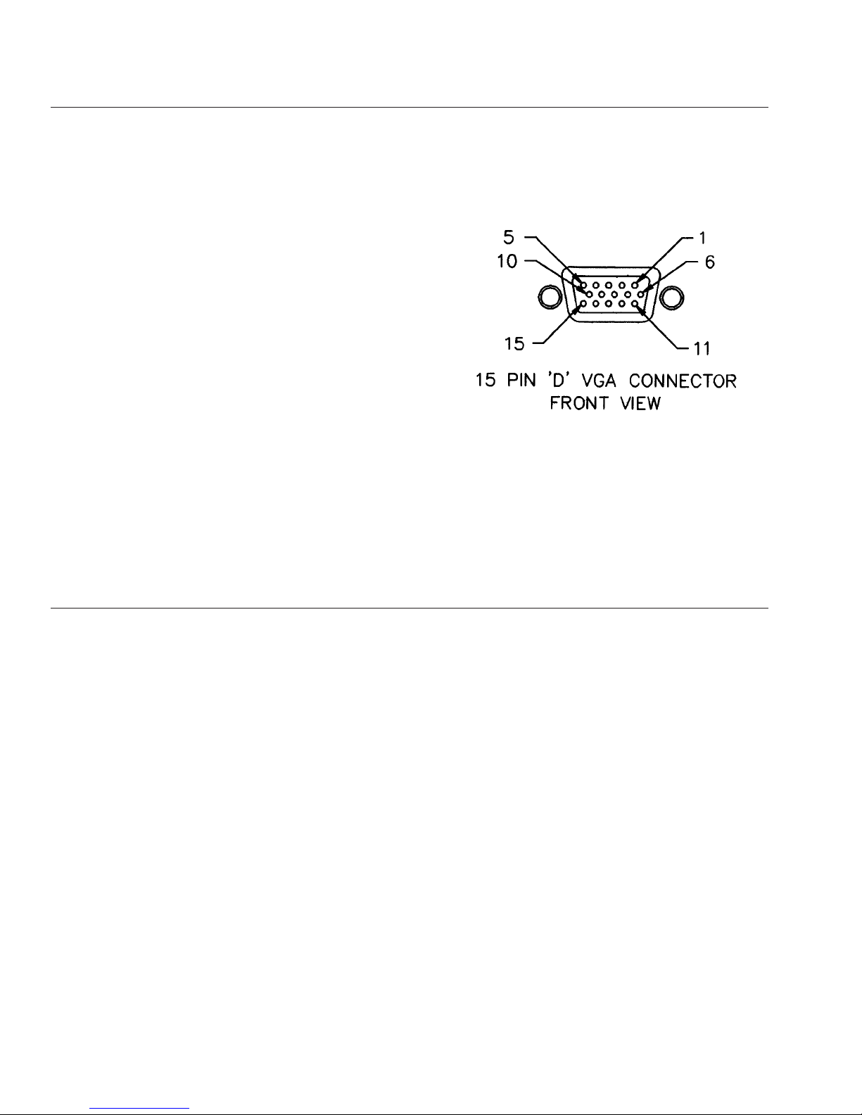
VGA Connector Pinout
Pin Function
1 Red Video
2Green Video
3 Blue Video
4 Not Used
5Ground
6 Red Return (Ground)
7Green Return (Ground)
8 Blue Return (Ground)
9 Composite Sync
10 Composite Sync Return (Ground)
11 Not Used
12 Not Used
13 Horizontal Sync
14 Vertical Sync
15 Not Used
Figure 8
16
APPENDIX B
APPENDIX C
Page 18

17
SPECIFICATIONS
LD100 Specifications
INPUT SIGNALS (NTSC) 525 Line 2:1 Interlace
Video 1Vp-p, Negative Sync
714mV Luminance
Y/C Y/C (3.58) Non-Composite
700m/Vp-p Y
286mVp-p C (Burst)
RGB 700mVp-p Non-Composite,
1Vp-p Composite
Component Y(1V w/Sync), R-Y(714mV),
B-Y(714mV)
Composite Sync Negative, > 4Vp-p Composite
OUTPUT SIGNALS (NTSC) 525 Line Progressive
Scan/1050 Line per Frame
R, G, B Non-composite, Positive,
714mVp-p
Vertical Sync 59.94Hz, Negative, 4Vp-p,
75 Ohm
Horizontal Sync 31.5KHz, Negative, 4Vp-p,
75 Ohm
Composite Sync 31.5KHz/59.94Hz, Negative,
4Vp-p, 75 Ohm
VGA Standard 15 Pin ‘D’ Connector,
VGA Standard
LUMINANCE
Input Conditions Low-Pass Filter: -3db @ 11MHz
Output Conditions Low-Pass Filter: -3db @ 22MHz
CHROMINANCE
Input Conditions Low-Pass Filter: -3db @ 6MHz
Output Conditions Low-Pass Filter: -3db @ 12MHz
PROPAGATION DELAY 1 Field + 2.5 Lines
POWER CONSUMPTION 100-250 VAC, 50/60Hz,
60W, Auto Ranging
FUSE 2 Amp, Slo-Blow AGC-2A
DIMENSIONS 17"W* x 3.5"H x 21"D
(43.1cm x 8.9cm x 53.3 cm)
WEIGHT 22 lbs. (9.8Kg)
NOTE: 625 lines 50Hz component or RGB signals are
usable with the LD100. Outputs are identical to those of
the LD100U in that mode.
*19" (48.26cm) with rack mount ears
Design and specifications are subject to change without notice.
LD100U Specifications
INPUT SIGNALS (NTSC) 525 Line 2:1 Interlace
Video 1Vp-p, Negative Sync
714mV Luminance
Y/C Y/C (3.58) Non-Composite
700m/Vp-p Y
286mVp-p C (Burst)
RGB 700mVp-p Non-Composite,
1Vp-p Composite
YUV Y(1V w/Sync), R-Y(714mV),
B-Y(714mV)
Composite Sync Negative, > 4Vp-p Composite
INPUT SIGNALS (PAL) 625 Line 2:1 Interlace
Video 1Vp-p, Negative Sync
700mV Luminance
Y/C Y/C (4.43) Non-Composite
700m/Vp-p Y
286mVp-p C (Burst)
RGB 700mVp-p Non-Composite,
1Vp-p Composite
YUV Y(1V w/Sync), U(700mV),
V(700mV)
Composite Sync Negative, > 4Vp-p Composite
OUTPUT SIGNALS (NTSC) 525 Line Progressive
Scan/1050 Line per Frame
R, G, B Non-composite, Positive,
714mVp-p
Vertical Sync 59.94Hz, Negative, 4Vp-p,
75 Ohm
Horizontal Sync 31.5KHz, Negative, 4Vp-p,
75 Ohm
Composite Sync 31.5KHz/59.94Hz, Negative,
4Vp-p, 75 Ohm
VGA Standard 15 Pin ‘D’ Connector,
VGA Standard
OUTPUT SIGNALS (PAL) 625 Line Progressive
Scan/1250 Line per Frame
R, G, B Non-composite, Positive,
700mVp-p
Vertical Sync 50Hz, Negative, 4Vp-p, 75 Ohm
Horizontal Sync 31.2KHz, Negative, 4Vp-p,
75 Ohm
Composite Sync 31.2KHz/50Hz, Negative,
4Vp-p, 75 Ohm
VGA Standard 15 Pin ‘D’ Connector,
VGA Standard
LUMINANCE
Input Conditions Low-Pass Filter: -3db @ 11MHz
Output Conditions Low-Pass Filter: -3db @ 22MHz
CHROMINANCE
Input Conditions Low-Pass Filter: -3db @ 6MHz
Output Conditions Low-Pass Filter: -3db @ 12MHz
PROPAGATION DELAY 1 Field + 2.5 Lines (NTSC)
1 Field +3.5 Lines (PAL)
POWER CONSUMPTION 100-250 VAC, 50/60Hz,
60W, Auto Ranging
FUSE 2 Amp, Slo-Blow AGC-2A
DIMENSIONS 17"W* x 3.5"H x 21"D
(43.1cm x 8.9cm x 53.3 cm)
WEIGHT 22 lbs. (9.8Kg)
*19" (48.26cm) with rack mount ears
Design and specifications are subject to change without notice.
Page 19

WARRANTY INFORMATION
All FAROUDJA Laboratories products are warranted to the original purchase against
defective materials and workmanship under normal use and service for a period of one
(1) year from the date of shipment. This warranty shall be of no force and effects if modifications have been made by the purchaser or its agents or employees or if damage
results from connecting the product to incompatible equipment or power. This warranty
will also be void if the product is not returned to FAROUDJA Laboratories in the original
shipping container.
The purchaser’s sole remedy with respect to the breach of this warranty is for the selling distributor to repair or replace, at its option, those products which the selling distributor determines to have breached this warranty within the specified period.
Any claims under this warranty should be made by telephone or in writing to the selling
distributor or FAROUDJA Laboratories. No products should be returned to the selling
distributor or to FAROUDJA Laboratories without its prior consent, and then, only with
freight prepaid. FAROUDJA Laboratories will prepay the return shipment.
Specifications and price change privileges are reserved.
THIS WARRANTY IS IN LIEU OF ALL OTHER WARRANTIES EXPRESSED OR
IMPLIED INCLUDING, WITHOUT LIMITATIONS, ANY IMPLIED WARRANTY FOR
MERCHANTABILITY OR FITNESS FOR A PARTICULAR PURPOSE.
FAROUDJA Laboratories
750 Palomar Ave., Sunnyvale, California 94086
Tel: 408-735-1492 Fax: 408-735-8571
18
 Loading...