

Page 1

Table of contents
IMPORTANT SAFETY INSTRUCTIONS ................................................................. 3
1 PACKAGING AND CONTENTS ............................................................................... 4
2 INTRODUCTION ..................................................................................................... 4
3 INSTALLATION ........................................................................................................ 5
4 SWITCHING ON AND OFF THE PROJECTOR ...................................................... 7
Switch on from stand-by .................................................................................. 7
Switching off and returning to stand-by ........................................................... 7
Led indicators .................................................................................................. 7
5 CONNECTIONS ...................................................................................................... 8
Composite video input ..................................................................................... 8
S-VIDEO input ................................................................................................. 8
VGA input ........................................................................................................ 8
RGB/YCrCb Input ............................................................................................ 8
DVI-D ............................................................................................................... 9
Remote Input Interface connecting cable ........................................................ 9
Motorised projection screen output ................................................................. 9
RS232 Interface connector .............................................................................. 9
6 KEYBOARD PAD ................................................................................................... 10
7 REMOTE CONTROL ............................................................................................. 10
8 ON SCREEN MENUS............................................................................................ 12
Source selection ............................................................................................ 12
Main menu ..................................................................................................... 12
Picture ........................................................................................................... 12
Image adjustments ........................................................................................ 13
Setup ............................................................................................................. 15
Menu ............................................................................................................. 16
Info ................................................................................................................ 16
Quick menus ................................................................................................. 17
Messages ...................................................................................................... 17
9 CLEANING AND MAINTENANCE ......................................................................... 17
10 TROUBLESHOOTING GUIDE .............................................................................. 17
11 OPTIONAL ACCESSORIES .................................................................................. 18
A TECHNICAL SPECIFICATIONS ............................................................................ 19
B PROJECTION DISTANCES .................................................................................. 20
C DIMENSIONS ........................................................................................................ 20
Page 2
CAUTION
RISK OF ELECTRIC SHOCK!
DO NOT REMOVE THE TOP COVER
ATTENTION:
To reduce the risk of electric shock, disconnect the power supply cable on the rear panel
before removing the top cover of the projector.
Refer to trained, authorised personnel for technical assistance.
Prior to switching on the projector please read each chapter of this manual carefully as this manual provides basic instructions
for using the projector.
The installation of the lamp assembly, preliminary adjustments and procedures that necessitate the removal of the top cover,
must be carried out by authorised, trained technicians. There are no user serviceable parts inside. To ensure safe and long term
reliability please use power cables supplied with the projector. Observe all warnings and cautions.
••
• Federal Communication Commission (FCC Statement)
••
This equipment has been tested and found to comply with the limits for a Class B digital device, pursuant to Part 15 of the FCC
rules. These limits are designed to provide reasonable protection against harmful interference when the equipment is used in a
commercial environment. This equipment generates, uses and can radiate radio frequency energy and, if not installed and used in
accordance with the instruction manual, may cause harmful interference to radio communications. However, there is no guarantee
that interference will not occur in a particular installation. If this equipment does cause harmful interference to radio or television
reception, which can be determinated by turning the equipment off and on, the user is encuraged to try to correct the interference
by one or more of the following measures:
- Reorient or relocate the receiving antenna
- Increase the separation between the equipment and receiver.
- Connect the equipment into an outlet on a circuit different from that to which the receiver is connected.
- Consult the dealer or an experienced radio/TV technician for help.
!
••
• For customers in Canada
••
This Class B digital apparatus complies with Canadian ICES-003.
••
• For customers in the United Kingdom
••
ATTENTION: This apparatus must be earthed
The wires in this mains lead are coloured in accordance with the following code:
Green-and-Yellow: Earth
Blue: Neutral
Brown: Live
As the colours of the wires in the mains lead of this apparatus may not correspond with the coloured markings identifying the
terminals in your plug proceed as follows:
The wire which is coloured green-and-yellow must be connected to the terminal in the plug which is marked by the letter E or by the
safety earth symbol
The wire which is coloured blue must be connected to the terminal which is marked with the letter N or coloured black.
The wire which is coloured brown must be connected to the terminal which is marked with the letter L or coloured red.
Trademarks
DLP and DMD are trademarks of Texas Instruments.
or coloured green or green-and-yellow.
2
Page 3
IMPORTANT SAFETY INSTRUCTIONS
Please follow carefully the warnings listed below, to ensure safe
and long term performance of your projector.
••
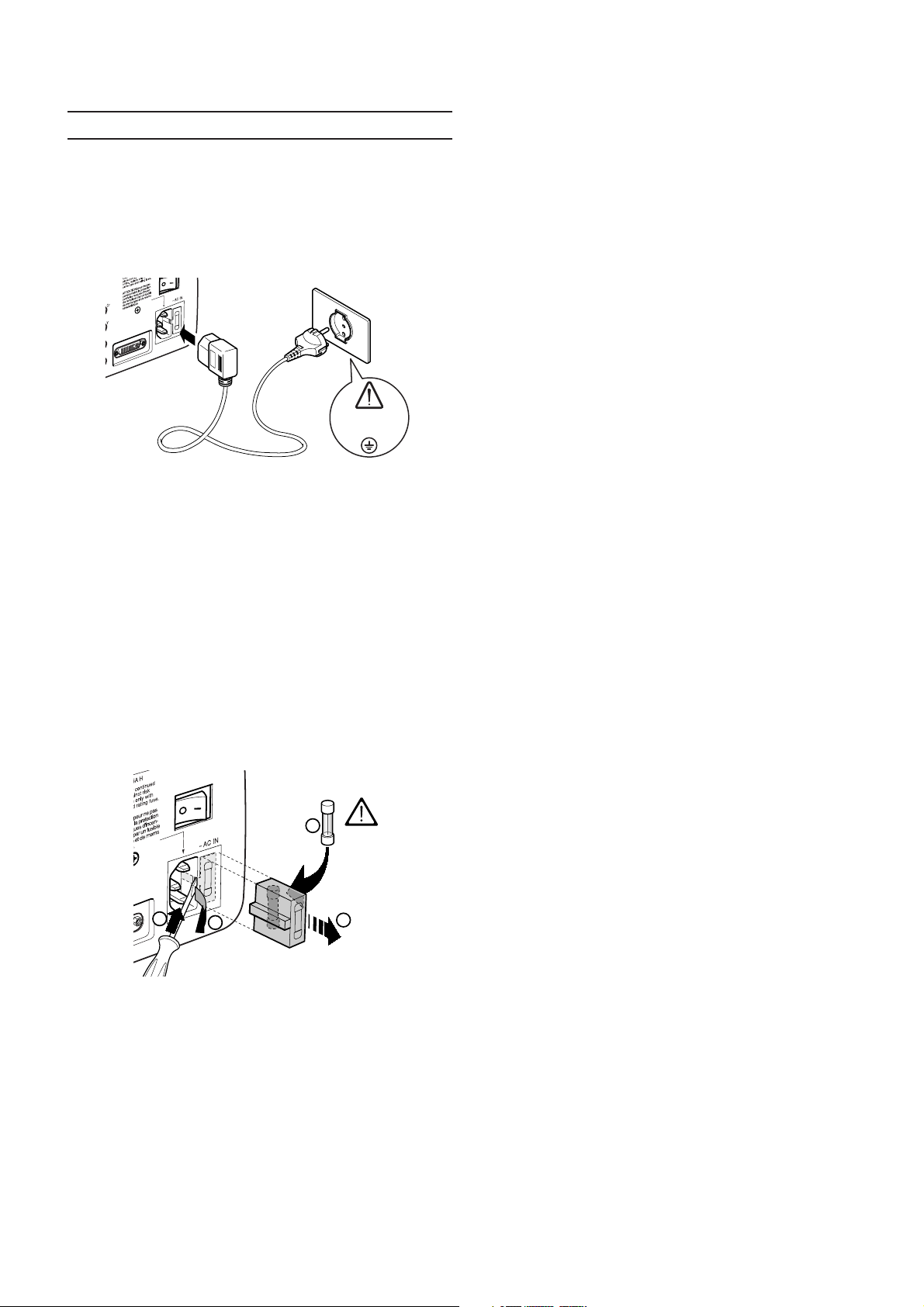
• Connect the projector to a power supply with a nominal voltage
••
within the following values: 100-240 Vac, 50/60 Hz, earthed
(Fig. 1)
.
DVI
••
• Do not switch on your projector when flammable liquids or
••
fumes are present. Do not pour or drop fluids in the vents.
••
• Do not use the projector when the room temperature is above
••
35°C (95°F).
••
• Do not obstruct the cooling air inlets on the top cover, or the
••
air outlets underneath the projector.
••
• Do not switch on the projector if it is standing on soft surfaces
••
such as cushions, pillows, blankets, mattresses and carpets:
the air cooling outlets underneath could become obstructed.
••
• Do not switch-on the projector if it is standing on surfaces
••
sensitive to heat, as this may result in damage caused by the
hot air outlets underneath. Should this be unavoidable take
extra precaution of protecting the surfaces with a layer of
heat resistant material.
100-240 Vac
50/60 Hz
Fig. 1
••
• The mains plug is the disconnect device. Take care, when
••
installing, that the mains plug and socket outlet are easily
accessible. Never pull on the cable to take it out of the socket.
If the system is unlikely to be used for a number of days,
disconnect the power cable and other apparatus connected
to it.
••
• To save energy, switch off the projector by using the power
••
switch at the rear; when in stand-by (red light on) the projector
continues to draw a minimal amount of power.
••
• Only replace the safety fuse (on the power socket at the rear
••
of projector) with a fuse identical in type and characteristics
(T 3.15A H)
(Fig. 2)
.
4
250 V
T 3.15A H
••
Intense Light Source! Do not stare directly into the projection
•
••
lens as possible eye damage could result. Be especially careful
that children do not stare directly into the beam.
••
•
Do not open the projector’s cover; no user serviceable parts
••
are inside. Refer servicing to qualified service personnel.
Opening the projector’s cover will invalidate warranty
••
• Take care not to shake the projector whilst carrying it by the
••
.
handle.
••
• Always position the projector away from direct heat sources.
••
••
• Do not touch the surface of the projection lens.
••
••
• The projector must be positioned on a stable, suitable platform
••
or be installed using a bracket for fixed ceiling or wall
installation. Do not rest the projector on the side panels or on
the rear panel when in operation.
••
• Take care to position cables safely, especially in dark places,
••
in order to avoid a trip hazard.
••
• For installations using a ceiling or wall-mounted bracket,
••
carefully follow the installation and safety instructions provided
with the bracket’s literature.
••
• Please remove batteries from the remote control if not in use
••
for a long period of time.
1
2
3
••
• A special EVC socket on the projector’s rear panel will allow
••
connection to the optional Remote Input Interface (a special
cable is required).
This is not to be confused with a VESA “Plug & Display”.
Never connect a computer to this socket, as the projector
Fig. 2
and the computer may be damaged.
3
Page 4
1 PACKAGING AND CONTENTS
1
2
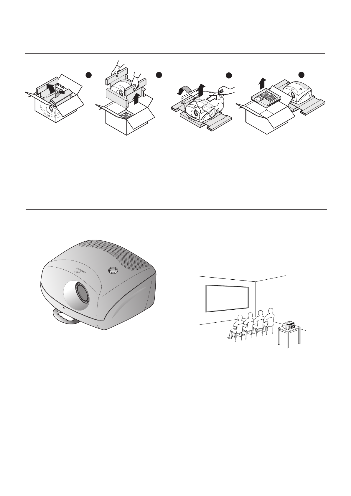
The carton should contain the following:
- the projector
- the remote control
- four 1.5V AAA batteries (for remote control)
- three power cables (EU, UK, USA)
- the user manual.
2 INTRODUCTION
Congratulations and thank you for choosing the FDP-DLPHD10,
a Faroudja product
(Fig. 4)
.
3
4
Fig. 3
To unpack the projector safely and easily please follow steps 1
to 4, as per drawing
It is recommended that the carton and packaging is retained for
future use and in the unlikely event that your projector needs to
be returned for repair.
A sophisticated proprietary optical system, coupled with a hight
performance zoom lens ensures hight contrast images, superior uniformity and edge-to-edge definition.
A new 6-segment colour wheel dramatically reduces the so called
“rainbow effect” and gives a better contrast, better colorimetry
and a lower black level to the image.
(Fig. 3).
Fig. 4
The FDP-DLPHD10 incorporates patented Faroudja technology
for deinterlacing, color and detail processing, including DCDi
technology. The result is that all sources are converted to very
clean video signals full of detail and color while free of typical
artifacts such as stairstepping and motion breakup.
Using the very latest in DLP™ technology, this projector has
been designed specifically for high quality “Home Cinema”
applications.
Sophisticated digital processing and a wide choice of inputs
enable the connection of a variety of sources such as DVD players, analogue and digital VCRs, analogue and digital satellite
receivers and personal computers etc.
The long throw zoom lens allows the position of the projector to
be located behind the viewer, thus reproducing a cinema-like
installation
(Fig. 5)
.
I
V
D
C
N
Y
S
C
The new HD-2 DMD™ chip ensures, on top of the high definition resolution (1280 x 720 pixels), an increased contrast ratio
of > 1800:1 thus delivering on the screen an even more realistic
image.
The DVI-D input allows a complete digital connectivity to an increasing amount of video sources equipped with digital outputs,
thus guaranteeing a perfect reproduction, without any loss of
information or interference in the signal.
The low-noise ventilation system – with variable speed fans –
ensures appropriate cooling and maximizes projector reliability.
To fully appreciate your new projector we recommend the use
of a good quality screen and surround-sound system. Contact
your nearest authorized Faroudja dealer for further details.
4
Fig. 5
Page 5

1
2
3
5 8
7
1 Projection lens
2 Lens shift knob
3 Cooling air inlet vents
4
6
4 Remote control IR sensor
5 Cooling air outlet vents
6 Adjustable carry-handle
7 Adjustable levelling feet
12
8 Ceiling/wall bracket fixing holes
13 17
11
9 Fused power socket
10 Main power switch
10
11 Remote control rear IR sensor
12 Green LED
14
15
16
22
C-SYNC
21
9
DVI
19
18
13 Red LED
14 Rear keyboard pad
15 Composite video input
16 S-Video input
17 VGA input
18 RGB / YCrCb input
19 DVI-D
20 12Vdc screen output
21 RS232 interface connector
22 Remote Input Interface EVC
20
connector
3 INSTALLATION
Position the projector on a stable, suitable platform or utilise
the optional bracket for a fixed ceiling or wall installation.
CAUTION: In the case of ceiling or wall mounting using a
suspension bracket, follow the instructions carefully and
comply with the safety standards you will find in the box
together with the bracket. If you use a bracket different to
the one supplied by Faroudja, you must make sure that the
projector is at least 65 mm (2-9/16 inch) from the ceiling
and that the bracket is not obstructing the air vents on the
lid and on the bottom of the projector.
Adjust the feet underneath to obtain a level position, lining up
the base of the projected image to the base of the projection
(Fig. 6)
screen
.
I
V
D
C
N
Y
S
C
Fig. 6
Position the projector the desired distance from the screen: the
size of the projected image is determined by the distance from
the lens of the projector to the screen and the zoom setting. See
“Appendix B”: Projection distances” for more information.
Use the motorised lens zoom to adjust the image size and the
motorised lens focus to achieve maximum clarity. With optimum
focus you should be able to clearly see each single pixel when
(Fig. 7)
within close proximity to the screen
ZOOM
ZOOM
FOCUS
FOCUS
FOCUS
ZOOM
FOCUS
ZOOM
.
ZOOM
I
V
D
NC
C-SY
Fig. 7
The manual lens shift adjustment allows the projected image to
be moved vertically, up or down, in relation to the centre of the
5
Page 6
your nearest authorized Faroudja dealer for further details.
C
-
S
Y
N
C
D
V
I
C
-S
YN
C
D
V
I
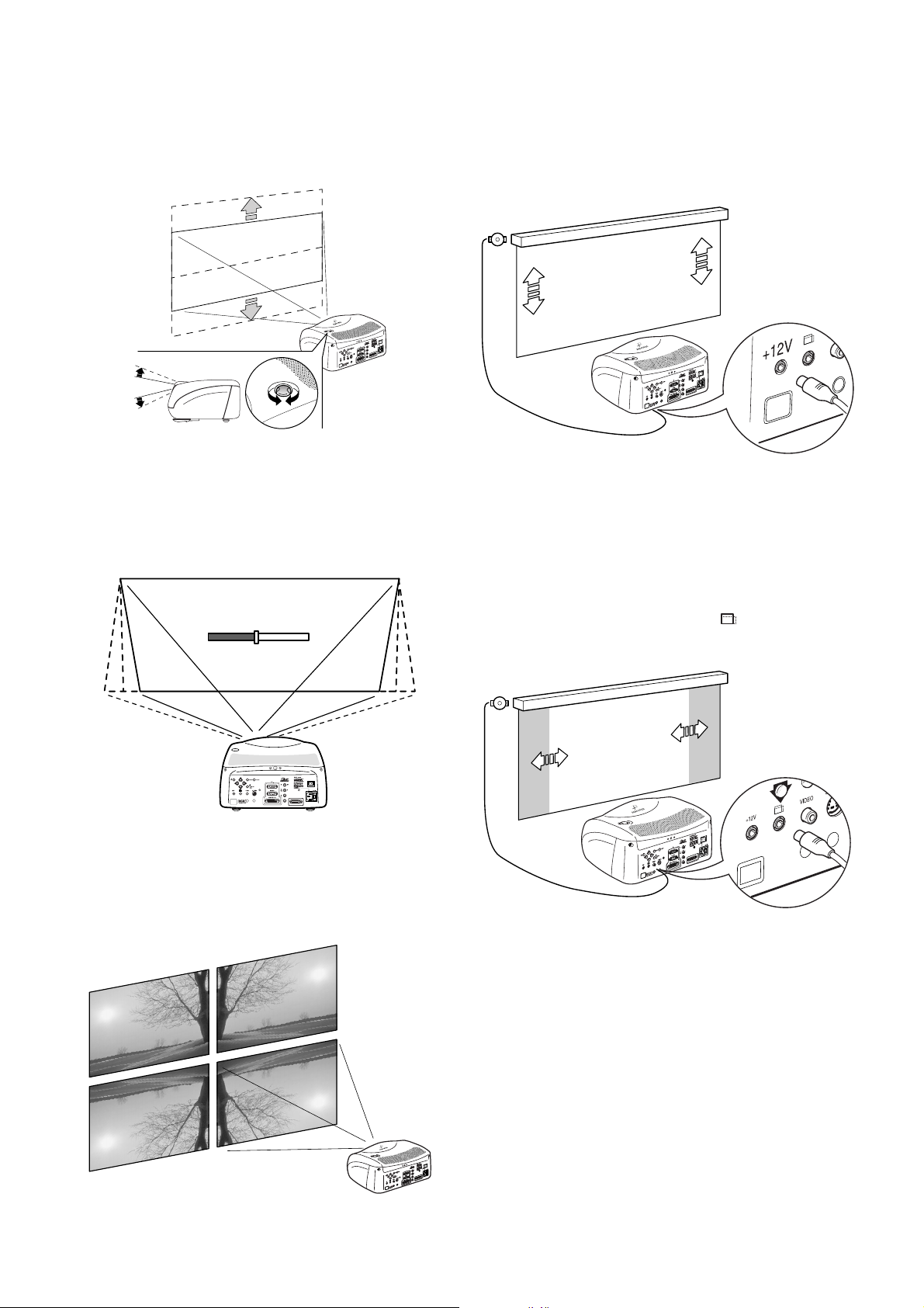
screen; the maximum adjustment being equal to half the height
of the image in either direction
(Fig. 8)
.
I
V
D
NC
SY
C
Fig. 8
In the event you are unable to centre the image within the screen
area, tilt the projector until the image is correctly positioned.
Any keystone error can be removed by the Keystone adjustment
in the Set up menu
(Fig. 9)
.
To activate an electric motorised screen a 12 Volt output is
provided at the rear of the projector or with the optional Remote
Input Interface. This can be connected to a screen interface
unit, which can be supplied by screen manufacturers
(Fig. 11)
Fig. 11
The output is activated (Voltage: 12 Vdc) when the projector is
switched on and is de-activated (no Voltage output) when the
projector is in stand-by mode.
.
KEYSTONE
20%
DVI
C-SYNC
Fig. 9
The Orientation adjustment in the Set up menu will allow the
projector to be used for desktop front, ceiling front, desktop rear
and ceiling rear installations
(Fig. 10)
.
Some manufacturers offer screen-masking systems to help frame the projected image and improve picture contrast. These
systems can be connected to output
projector
(Fig. 12)
, or on the optional Remote Input Interface.
, at the rear of the
Fig. 12
For rear projection the screen must be translucent.
For front projection, we recommend the use of screens with low
gain specifications (i.e. 1.3 to 2). The use of high gain screens
should be avoided due to their limited viewing angle, which is
undesirable for a large audience.
Preferably, use a screen with black, non-reflecting borders, which
will perfectly frame the projected image.
Avoid light shining directly on the screen during projection as
this will reduce contrast and black level detail on the projected
image. For the true cinema experience best results are achieved
with little or no ambient light.
DVI
C-SYNC
Furniture and other objects with reflecting surfaces, as well as
light coloured walls should be avoided, as they are likely to
Fig. 10
interfere with the screen’s characteristics.
6
Page 7
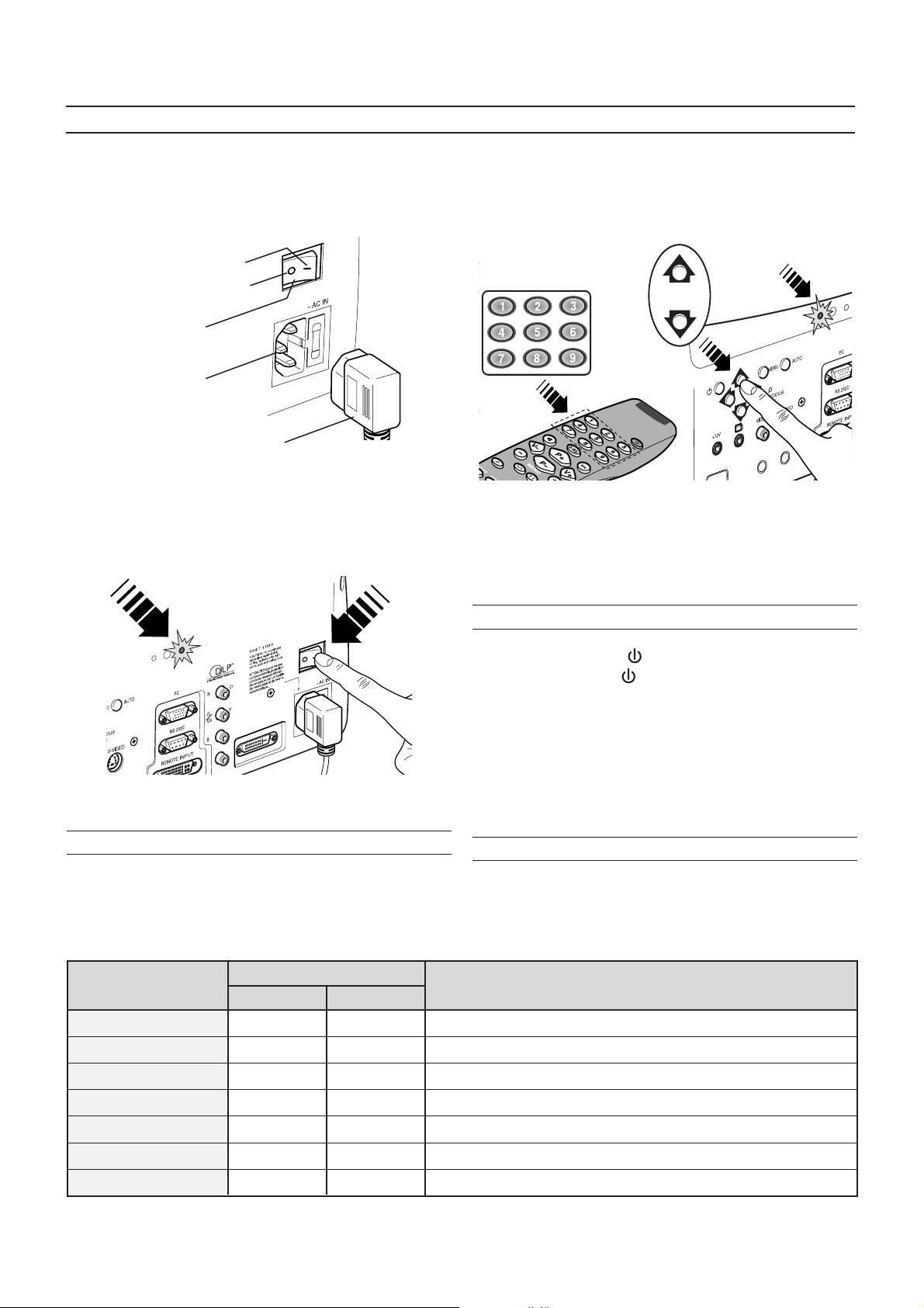
4 SWITCHING ON AND OFF THE PROJECTOR
CAUTION: Connect the projector to a power supply with a
nominal voltage within the following values: 100-240 Vac,
50/60 Hz. It must be earthed
Position I : ON
Position O : OFF
Power switch
Fused power socket
(Fig. 13)
Power plug
.
Fig. 13
Upon switch on (in position I) the projector will initialise (red and
green LEDs on). Followed by stand-by mode (red LED on)
(Fig.
14).
When switching on from stand-by, the projector will turn on the
lamp; after a brief warm up period the image will be displayed
(green LED on).The input automatically selected will be the last
one memorised prior to switch off
(Fig. 15)
.
Fig. 15
You may experience difficulties switching on the projector shortly
after switching off: the lamp may fail to come on as it is too hot.
Just wait a few minutes to cool it down.
DVI
C-SYNC
SWITCH ON FROM STAND-BY
By remote control: press one of 1...9
By keyboard: press Up or Down Arrow .
STAT E NOTES
POWER OFF
INITIALIZATION
INDICATORS
GREEN RED
OFF
ON
OFF
ON
SWITCHING OFF AND RETURNING TO STAND-BY
By remote control: press
By keyboard: press key
When switching off, the projector goes in to stand-by memorising
the input selection at the time of switch-off.
The fans will continue to work until the lamp has cooled down
(red and green LEDs flashing) and will stop automatically after
this period.
Fig. 14
Be sure to keep power to the projector on when the unit is turned
off to insure that the cooling fans function properly.
LED INDICATORS
The LED indicators, located in the top-rear of the projector,
provide information about the state of the projector (see table
below).
The Power is turned off
Power button has been pressed and the software is initialized (15 s)
STANDBY
OPERATING
COOLING LAMP
WARNING
ERROR
OFF
ON
FLASHING
OFF
ON
OFF
FLASHINGFLASHING
OFF
FLASHING
Projector is in standby mode
Projector is on
Projector is powering down; the fans are running to cool the lamp (1 min)
Problems to display one or more source
Internal circuit failure
7
Page 8
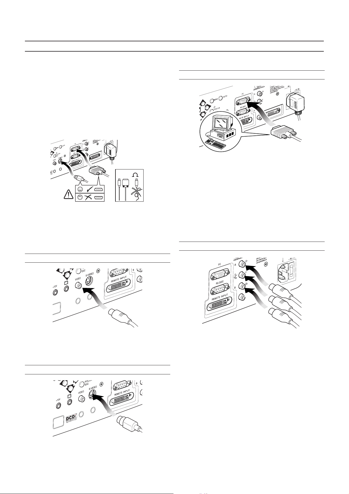
5 CONNECTIONS
To obtain the best performance from your projector, we
recommend the use of good quality “video cables” to the various
signal sources (75 ohm Impedance).
Poor quality cables will cause inferior picture performance.
For optimum connectivity we recommend you follow these simple
steps:
- With exception of coaxial RCA/Phono type connectors,
always double-check that the plug is inserted the correct way
round to avoid damaging the plugs or the sockets on the
projector
(Fig. 16)
.
I
V
D
C
N
Y
-S
C
75
Fig. 16
- Remove cables by the plug and do not pull on the cable itself.
- Avoid tangled cables.
- Position the cables carefully to avoid a trip hazard - especially
in low light areas.
Connection is made via a 4-pin mini-DIN
(Fig. 18)
.
VGA INPUT
DVI
C-SYNC
Fig. 19
Personal Computers, Video Processors (scalers) and Video
Game consoles can be connected to the projector via the HDB
15-Pin (VGA) terminal.
Ensure the output of equipment connected is RGB with one of
the following synchronisation options: separate H/V Sync, H+V
Composite Sync, (RGsB) composite sync on the green signal
(Fig. 19)
between 15-80 kHz and a Vertical frequency of between 40-100
Hz. Computer Resolutions of VGA, SVGA, XGA, SXGA and
UXGA can be displayed.
RGB/YCRCB INPUT
. This input accepts a Horizontal Scan Frequency of
COMPOSITE VIDEO INPUT
CVBS
COMPOSITE VIDEO
Fig. 17
This input is suitable for a “Composite Video CVBS” via a cable
with an RCA/Phono connector
S-VIDEO INPUT
(Fig. 17)
.
C-SYNC
RGSB - YSCRC
COMPONENT
VIDEO
B
Fig. 20
This input is suitable for a RGB video signal, or for a Component
(YCrCb) type, with composite synchronisation on the green
signal (RGsB) or on the luminance (Y) signal (YsCrCb) through
a cable with RCA/Phono type connector
Only horizontal scanning frequencies of 15 kHz (standard video
resolution) or 32 kHz (high definition video, with progressive
scanning) can be applied to this input.
(Fig. 20)
.
S-VIDEO
Fig. 18
This input is suitable for equipment fitted with a S-Video output
to give improved picture performance (S-VIDEO/S-VHS)
8
Page 9
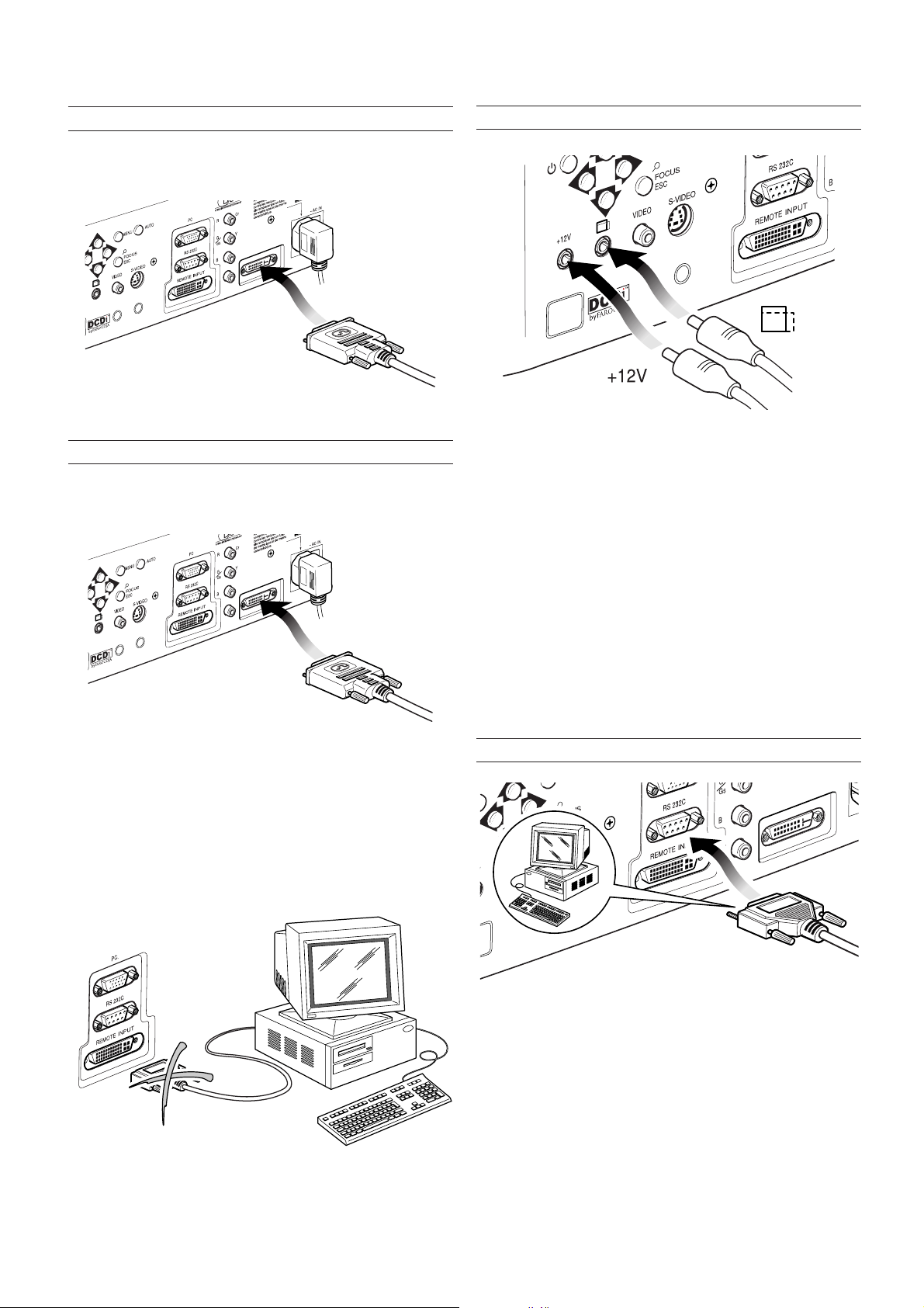
SYNC
RS 232
DVI
DVI INPUT
MOTORISED PROJECTION SCREEN OUTPUT
A DVI-D signal (digital RGB) can be applied to this input (
21)
.
DVI
C-SYNC
Fig.
Fig. 21
REMOTE INPUT INTERFACE CONNECTING CABLE
With a special cable (optional), it is possible to connect the Remote Input Interface (optional) to the projector(
DVI
Fig. 22)
.
Fig. 24
The projector is equipped with two outputs (Voltage: 12 Vdc) for
motorised projection screen and screen masking systems. These
12V outputs should be connected to the appropriate screen
interface provided by the screen manufacturer
The +12V output is activated when the projector is switched on
(green LED on) and is de-activated when the projector is in standby mode (red LED on).
(Fig. 24)
.
C-SYNC
Fig. 22
Connect/disconnect the special Remote Input Interface cable
only when the projector is switched off and disconnected from
the mains (switch in position O).
CAUTION: This is not a VESA “Plug & Display” connector.
Never connect a computer to this socket as the projector
and the computer may be damaged
(Fig. 23)
.
The output can be used to control a screen masking system;
its output can be set with the “Screen control” adjustment in the
“Aspect” menu.
This output allows reduction in the area of a 16:9 screen, into a
4:3 format, by activating a screen masking system (refer to
screen manufacturer for further information).
RS232 INTERFACE CONNECTOR
Fig. 25
It is possible to control the projector through a personal computer. First, load the appropriate projector control software onto
your PC, then simply connect this input to a cable from your
PC’s RS232 serial port
(Fig. 25)
.
Fig. 23
9
Page 10
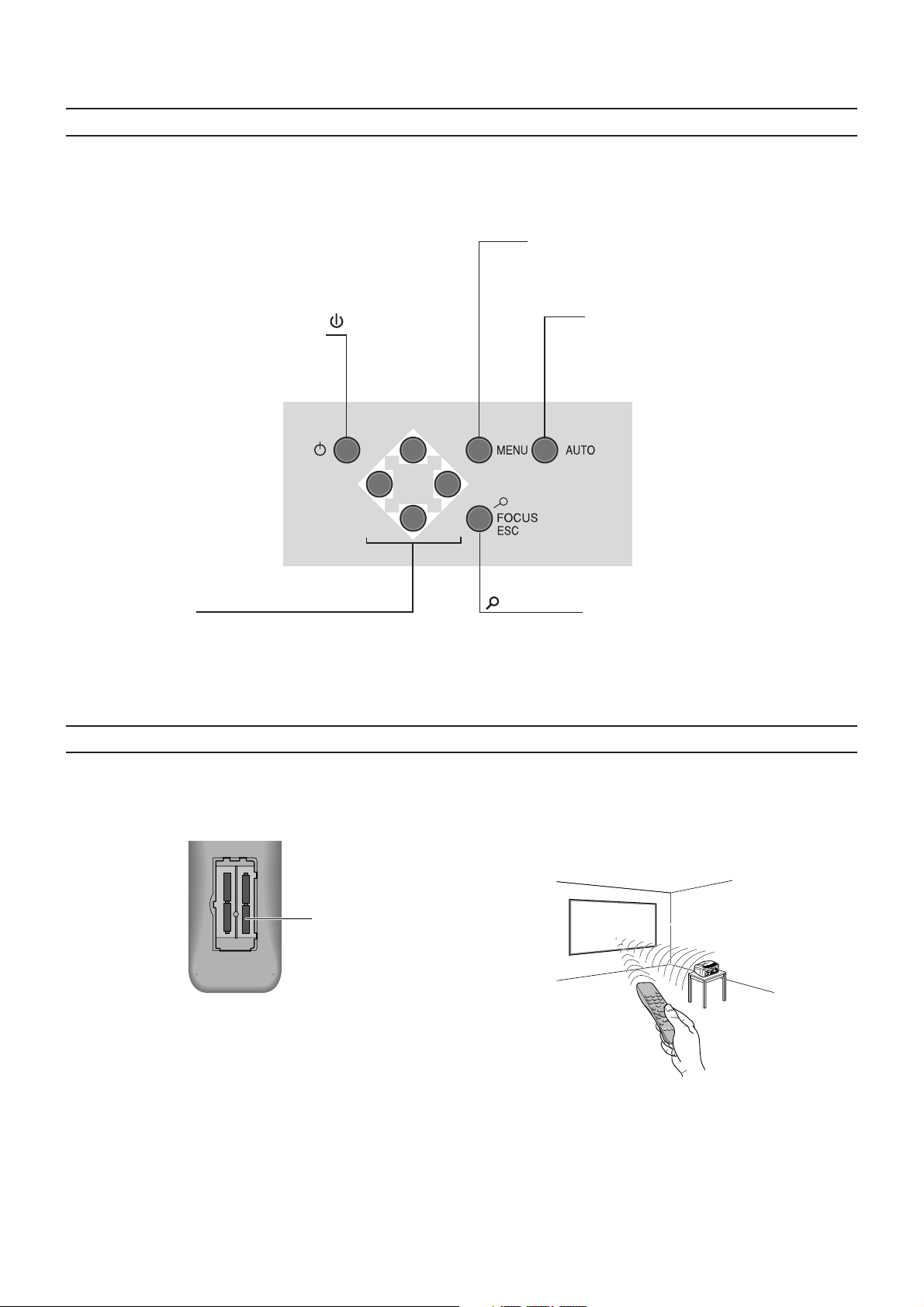
6 KEYBOARD PAD
Eight push buttons, at the rear of the projector, will allow complete operation without the use of the remote control.
Switches off to stand-by.
Menu
Activates the On Screen Display menus.
Navigates Menu pages.
Auto
Selects Auto Adjust
(automatic optimisation of the
displayed image).
Up/Down/Left/Right arrow keys
Navigate through and make adjustments
to the On Screen menus.
Arrow Up/Down switch on from stand-by
and recall Source Selection menu.
7 REMOTE CONTROL
The remote control requires four 1.5V, AAA alkaline batteries.
Insert the batteries, taking care to match the polarity, as indicated
in the battery recess of the remote
-
+
-
+
+
+
-
(Fig. 26)
four 1.5V
AAA alkaline
batteries
.
Fig. 26
-Focus-Esc
De-activates the On Screen Display and gives access to the
lens Zoom/Focus adjustment
functions.
The remote control sends commands to the projector via infrared
signals.
It is possible to control the projector by pointing the remote control
at the screen; the sensor at the front of the projector will pick up
the reflected infrared commands.
(Fig. 27)
.
I
V
D
C
N
Y
S
C
Change the batteries in the remote control if experiencing
difficulty in sending commands to the projector.
If the remote control is not to be used for a long period of time
remove the batteries. Replace all batteries at the same time; do
not replace one new battery with a used battery. If the batteries
have leaked, carefully wipe the case clean and replace with new
batteries.
Fig. 27
Avoid placing obstructions between the remote control and the
infrared sensor at the front of the projector; this will impair the
remote control performance.
10
Page 11
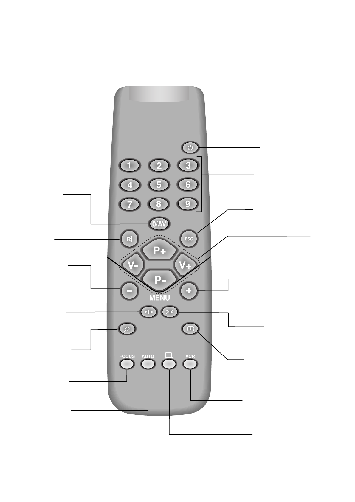
SOURCE
Displays the Source
Selection menu.
STAND-BY
Switches off to stand-by.
0-9 Keys
Switch on from stand-by
and allow direct source
selection.
ESCAPE
Deactivates the On Screen Display.
Not active
in this model.
MENU -
Activates the On Screen
Display menus.
Navigates menu pages.
FREEZE
Freezes a moving
picture.
ZOOM
Selects lens zoom
adjustment.
FOCUS
Selects focus
lens adjustment.
AUTO
Selects Auto Adjust
(automatic optimisation
of the displayed image).
Up/Down/Left/Right Arrow keys
Navigate through and make adjustments
to the On Screen menus.
Arrow Up/Down activate Quick
menus.
MENU +
Activates the On Screen Display menus.
Navigates menu pages.
Not active
in this model.
INFO
Displays the selected source information
and the projector status.
VCR
Improves the video recorder
signals quality.
ASPECT
Selects image Aspect ratio.
11
Page 12
8 ON SCREEN MENUS
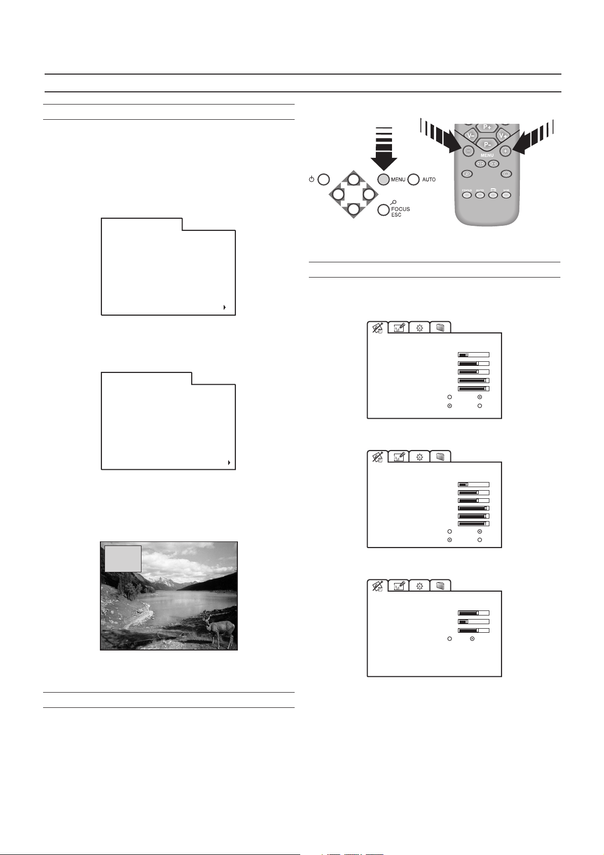
SOURCE SELECTION
The Source Selection menu is recalled by pressing the key:
0/AV of the remote control or the Up/Down Arrow key of the
keyboard pad. The selected source will be highlighted in yellow.
Use Up and Down Arrow keys to browse sources. Right Arrow
to select the desired source.
Alternatively, use the remote control to directly select the required
source (1 to 8).
Source Selection
1
Video
2
S-Video
3
RGBS 15 kHz
4
YCrCb 15 kHz
5
RGBS 32 kHz
6
YCrCb 32 kHz
7
Graphics RGB
8
DVI-D
0
RI2 inputs
When using the optional Remote Input Interface press the 0/AV
key twice to display Remote Input Interface sources.
Source Selection / RI2
Video 1
1
Video 2
2
S-Video 1
3
S-Video 2
4
RGBS 15 kHz
5
YCrCb 15 kHz
6
RGBS 32 kHz
7
YCrCb 32 kHz
8
9 Graphics RGB
0
Projector Inputs
When a new source is selected a box appears on the screen
with the following indications: selected source, standard video
(for video signals), resolution (for graphic signals) and aspect
(Fig. 28).
Video
NTSC/60Hz
Normal
Fig. 29
PICTURE
This menu features adjustments relating to the projected image
quality.
PICTURE
BRIGHTNESS
CONTRAST
COLOR
SHARPNESS
FILTER
CINEMA MODE
VIDEO TYPE
20
50
50
7
6
Off
Normal
Auto
VCR
VIDEO
PICTURE
BRIGHTNESS
CONTRAST
COLOR
TINT 85
SHARPNESS
FILTER
CINEMA MODE
VIDEO TYPE
20
50
50
7
6
Off
Normal
Auto
VCR
VIDEO-NTSC
Fig. 28
MAIN MENU
To access the main On Screen Display menu, press the Menu
key on the keyboard or the key Menu + or Menu - on the remote control
(Fig. 29)
The main menu is divided into four sections to cover various
adjustments in a practical and logical manner.
The on-screen menu layout is dependant upon the chosen input
signal so various options may not be applicable, i.e. some typical
adjustments to the video signal are not applicable to the graphic
RGB signals from PC and viceversa.
.
PICTURE
BRIGHTNESS
CONTRAST
SHARPNESS 5
SHARPNESS MODE
50
20
Video
Graphics
RGB-DVI
BRIGHTNESS
Use this control to adjust the image’s black level.
CONTRAST
Use this control to adjust the image’s white level, be careful not
to over saturate the white level.
COLOR
Use this control to adjust the colour level.
12
Page 13
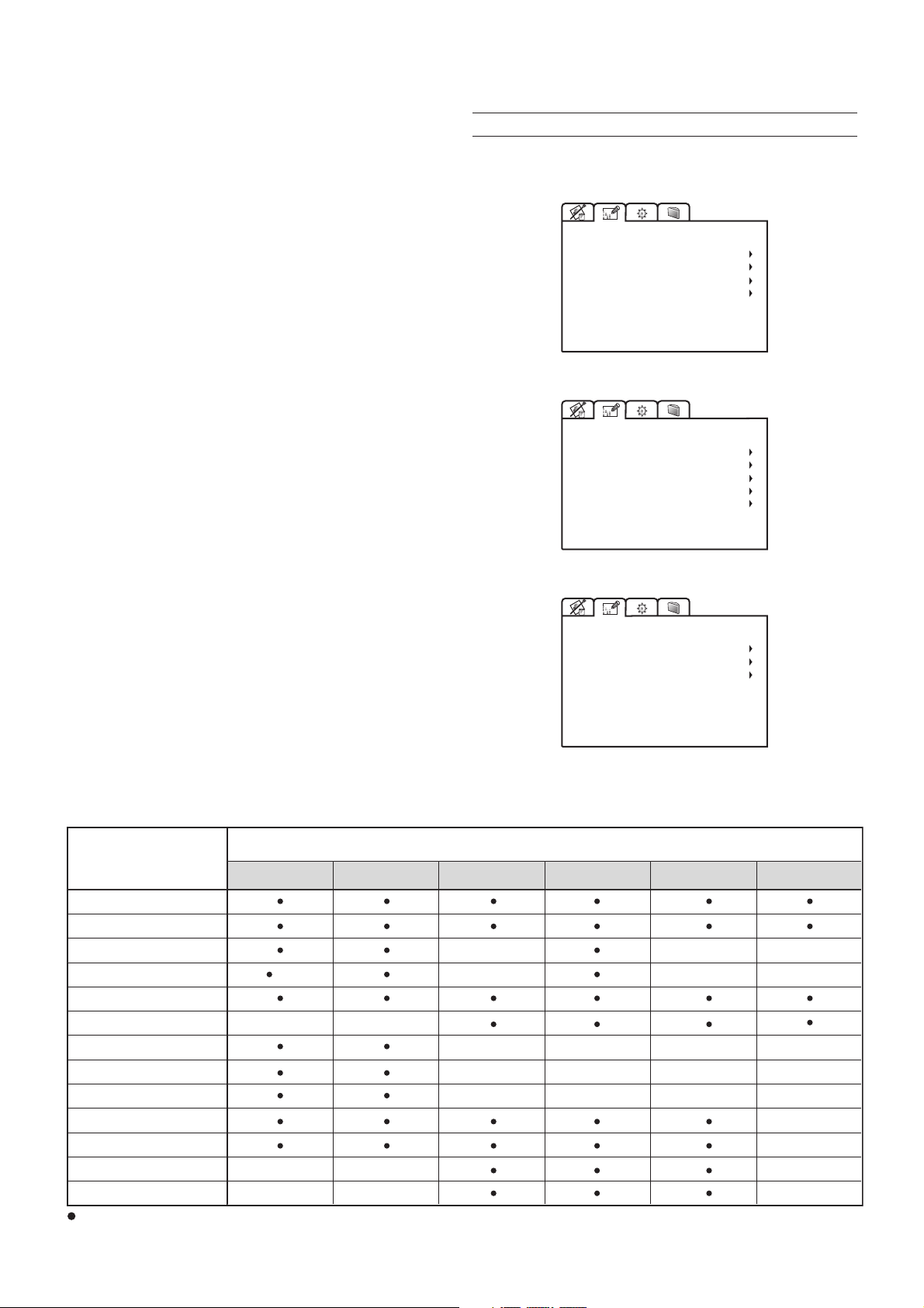
TINT
Controls the purity of the colours, to NTSC coded signal
standards. Tint is only applicable to video input with NTSC
standard, to RGB 15kHz and YCrCb 15kHz inputs and YCrCb
32kHz (no RI2).
IMAGE ADJUSTMENTS
This menu features adjustments relating to position, aspect ratio
and magnification etc.
SHARPNESS
Use this adjustment to increase and decrease the level of picture
detail.
SHARPNESS MODE
It allows to select the type of processing that determines the
detail. In progressive or de-interlaced video signals the Video
option is suggested, with graphic signals from a PC the Graphic
option is suggested.
FILTER
For video signals it improves the image’s horizontal/vertical
definition and sharpness.
CINEMA MODE
In Auto the de-interlacer recognizes if the video signal is
originated from a cinematographic film (resulting from Teleciné
with 3:2 or 2:2 Pull Down) and applies an interpolation algorithm
optimized for this type of signal.
Instead if the video signal does not originate from a
cinematographic film, or Off is chosen, the de-interlacer applies
a “Motion Compensated” algorithm optimized for signals coming
from a videocamera.
VIDEO TYPE
Inserts a filter that improves stability of images from videorecorders. To toggle between Normal and VCR mode, press
the VCR key on the remote control.
IMAGE ADJUSTMENTS
POSITION
ASPECT
ADVANCED SETTINGS
MAGNIFICATION
IMAGE ADJUSTMENTS
POSITION
ASPECT
FREQUENCY/PHASE
ADVANCED SETTINGS
MAGNIFICATION
IMAGE ADJUSTMENTS
ASPECT
ADVANCED SETTINGS
MAGNIFICATION
VIDEO
RGB
RGB-DVI
INPUT SIGNALS AND ADJUSTABLE/SETTING ITEMS
SOURCE
ADJUSTMENTS
BRIGHTNESS
CONTRAST
COLOR --
TINT
SHARPNESS
SHARPNESS MODE
FILTER
CINEMA MODE
VIDEO TYPE
HORIZONTAL POSITION
VERTICAL POSITION
FREQUENCY
PHASE
Video
S-Video
(NTSC)
--
--
--
adjustable/can be set
not adjustable/can not be set
-
(*)
not adjustable if RI2 input
RGBS 15kHz
YCrCb 15kHz
RGBS 32 kHz YCrCb 32 kHz RGB Graphics DVI-D
(*)
-
-
-
-
(*)
-
-
-
-
-
-
-
-
-
-
-
-
-
-
-
-
13
Page 14
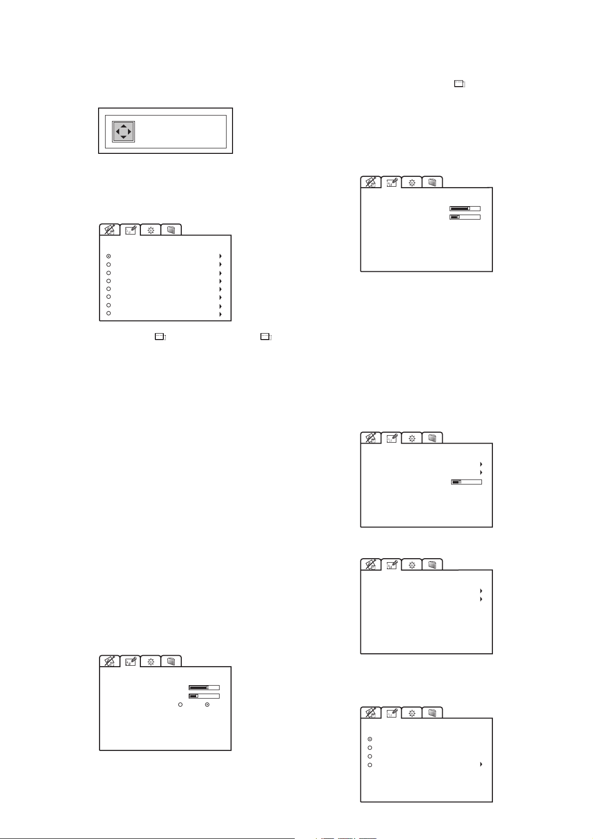
POSITION
Use this adjustment to position the image vertically and
horizontally.
Screen Control. If an appropriate screen-masking interface is
connected to the 12V output socket “ ” it is possible to reframe the screen to a variety of aspect ratios and screen sizes
(please refer to the screen manufacturer’s manual).
HORIZONTAL: 9
VERTICAL: 6
ASPECT
Determines the aspect ratio of the projected image.
From this menu it is possible to select the aspect ratio by using
the numeric keys 1...8 of the remote control.
ASPECT
1 NORMAL
2 ANAMORPHIC
3 LETTERBOX
4 PANORAMIC
5 PIXEL TO PIXEL
6 USER 1
7 USER 2
8 USER 3
By repeatedly pressing the key or by pressing the and
one of the numeric keys 1...8 of the remote control, it is possible
to select the aspect ratio.
Normal
This aspect projects the image occuping the full vertical
dimension of the screen and maintaining the correct aspect (4:3
or 16:9).
FREQUENCY / PHASE
In the case of RGB graphic signals this adjustment is used for
synchronization of the RGB image to the number of pixels on
the display panel.
FREQUENCY / PHASE
FREQUENCY
PHASE
1312
-12
RGB
Frequency
The correct frequency adjustment eliminates vertical band
interference.
Phase
The phase adjustment determines the stability and sharpness
of the vertical lines in the projected image.
ADVANCED SETTINGS
Advanced colour settings are accessible via this menu.
We recommend the use of these settings only to the experienced
user, as their adjustment can seriously affect final image quality.
Anamorphic
This aspect allows to properly visualize a 16:9 image.
Letterbox
This aspect allows to project a 4:3 letterbox image, filling the
16:9 screen and maintaining the correct aspect ratio.
Panoramic
This aspect stretches the 4:3 image slightly cutting the upper
and lower parts. It's ideal to project a 4:3 image in a screen of
16:9 aspect ratio.
Pixel to Pixel
This aspect projects the signal as it is input without scaling up
or down.
Image is projected in the center of screen.
User 1, 2, 3
Should you wish to use a format different to those preset, go to
User menus.
ASPECT / USER 1
HORIZONTAL
VERTICAL
SCREEN CONTROL
-10
0
On
Off
ADVANCED SETTINGS
COLOR TEMPERATURE
GAMMA CORRECTION
Y/C DELAY
ADVANCED SETTINGS
COLOR TEMPERATURE
GAMMA CORRECTION
2
Colour temperature
Select the colour temperature of the projected image.
VIDEO
RGB-DVI
By using the Horizontal and Vertical adjustments it is possible
to select the screen shape of your choice. It is important to keep
the relation between height and width so that the correct aspect
ratio can be maintained.
14
COLOR TEMPERATURE
HIGH
MEDIUM
LOW
USER
zione
Page 15
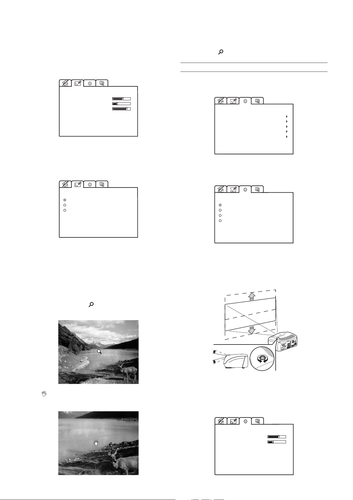
There are three fixed colour temperature settings, which are:
High (9000÷9500 degrees K), Medium (circa 6500 degrees K),
Low (circa 5000 degrees K).
The User option will allow you to select the colour temperature
of your choice.
COLOR TEMP. /USER
RED
GREEN
BLU
0
-16
28
Gamma correction
Selects the Gamma’s correction curve. It determines the
projector’s response to the grey scale, emphasizing - more or
less - the different grades of brightness (blacks, dark, medium,
light greys, whites) in the projected image.
Via remote control, it is possible to alternate between modes,
by pressing the key.
SETUP
The installation menu gives access to features that will allow for
correct installation of the projector.
SETUP
ORIENTATION
KEYSTONE
PROJECTION LENS
TEST PATTERNS
FACTORY DEFAULTS
ORIENTATION
Select the option that best describes the installation i.e. desktop
front, ceiling front, desktop rear and ceiling rear.
GAMMA CORRECTION
FILM
VIDEO
GRAPHICS
Y / C Delay
Use this adjustment in the event of horizontal colour misalignment
within the projected image. It is recommended that a colour bar
test pattern be used for this adjustment.
MAGNIFICATION
Use this adjustment to magnify the projected image (please note
the higher the magnification the poorer the quality of the image).
Adjust the level of enlargement using the Left and Right Arrow
(the magnifying lens icon
will appear at the centre of the
image).
ORIENTATION
FLOOR
CEILING
FLOOR-REAR
CEILING-REAR
HORIZONTAL / VERTICAL KEYSTONE
To obtain maximum quality of the projected image, we
recommend the installation of the projector on a level platform
parallel and central to the screen. In the event that the picture is
not correctly positioned use the lens shift feature
(Fig. 30)
I
V
D
C
N
Y
S
C
.
Select Pan (zoom button on the remote control) to choose
the area of image to enlarge, using all four arrow keys.
Should it not be possible to centralize the image by adjusting
the lens height, tilt the projector and use the keystone adjustment
to restore the projected image to the correct shape.
KEYSTONE
HORIZONTAL
VERTICAL
0
-10
15
Fig. 30
Page 16
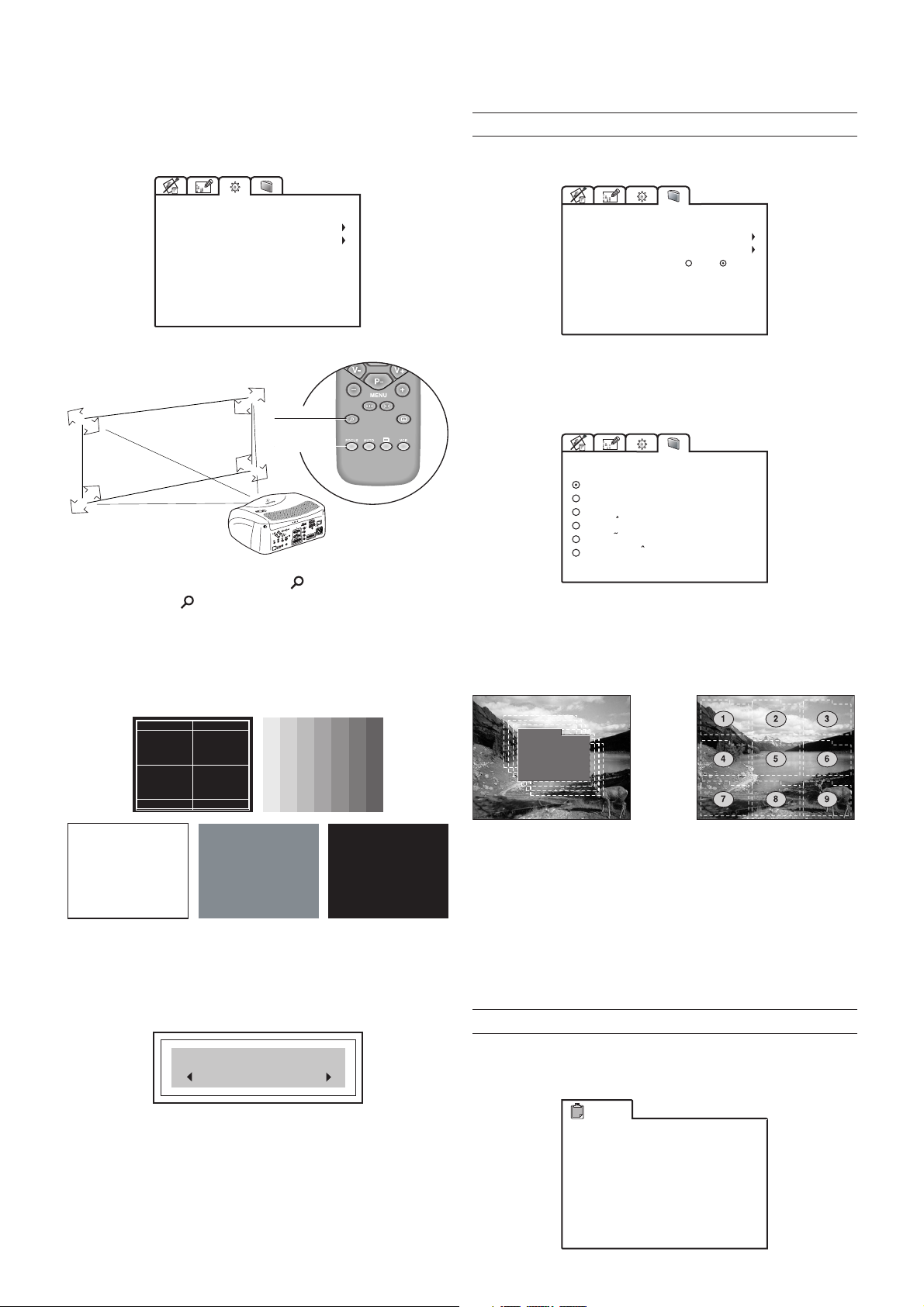
PROJECTION LENS
To adjust Focus and Size of the projected image, use the lens
settings.
MENU
This menu covers the On Screen Display adjustments.
PROJECTION LENS
FOCUS
ZOOM
ZOOM
ZOOM
ZOOM
FOCUS
I
V
D
C
N
Y
S
C
ZOOM
FOCUS
FOCUS
FOCUS
ZOOM
Alternatively, press keys Focus and (Zoom) on your remote
control, or the key -Focus-Esc on keyboard pad.
TEST PATTERNS
Displays a series of five test patterns, useful for the installation
of the projector.
Press Up and Down Arrow keys to browse pattern.
MENU
LANGUAGE
OSD POSITION
Clear
OSD BACKGROUND
OSD TIMEOUT
Solid
15 sec
LANGUAGE
Lists the languages options available for the On Screen Display
menus.
LANGUAGE
ENGLISH
ITALIANO
FRANCAIS
DEUTSCH
ESPANOL
PORTOGUES
OSD POSITION
To position the On Screen Display within the picture area, use
the arrow keys
control
(Fig. 31b)
(Fig. 31a)
.
or press the 1 to 9 keys on the remote
FACTORY DEFAULTS
Reconfigures the projector to original factory settings except
Position, Orientation, Y/C Delay, Zoom and Focus.
Confirm?
No
Yes
Fig. 31a Fig. 31b
OSD BACKGROUND
Gives a choice of backgrounds for the On Screen Display.
OSD TIMEOUT
Use this adjustment to set the display time after which the On
Screen Display will disappear. Left and Right Arrow keys set
the timing (within a 5-60 second timeframe).
INFO
This function displays the current status of the projector, input
type, input frequency, etc.
Info
Mode 4:3
Source
Standard Video
Horiz Frequency
Video Type Normal
Aspect
Color Temperature
Lamp Hour Meter
Software Version
Video
NTSC 60Hz/4.43MHz
15.7kHz
Panoramic
Low
362
2.08 H P (038)
16
VIDEO
Page 17

Info
Mode 4:3
Source
Horiz Frequency
Vertical Frequency
Resolution 1024x768 Mode:77
Aspect
Color Temperature
Lamp Hour Meter
Software Version
RGB Graphic
56.5kHz
70Hz
Normal
Low
362
2.08 H P (038)
RGB-DVI
QUICK MENUS
The Quick menus allows the adjustment of most of the picture
quality controls without recalling the main On Screen menus.
Brightness, Contrast, Color, Tint, Sharpness and Filter
adjustments appear at the bottom of the screen, one after
another, when Up and Down Arrow keys are pressed.
- Check that the selected input is actually connected to
a video or graphic signal.
- Verify compatibility of video/graphic signals with technical
specifications of your projector.
- Check the integrity of cables used to connect various sources.
- If you are using the Remote Input Interface, do not to confuse
the menu for selection of projector’s inputs (Source Selection),
with the menu for selection of remote inputs (Source Selection
/ RI2).
Out of range
Either the resolution or the horizontal/vertical frequency of the
input signal is too high.
- Input a signal that is within specifications.
MESSAGES
The following messages could appear on your screen:
No Signal
The projector does not recognise any signal sent through the
selected input.
9 CLEANING AND MAINTENANCE
The projector does not require internal cleaning. There are no
user serviceable parts inside the projector. Please refer all service
requirements to qualified personnel.
Cleaning the projector’s cover:
Use a soft slightly damp cloth. Do not use abrasive cleaners,
solvents or other harsh chemicals, as this will damage the finish
of the cover. Avoid direct cleaning of the rear panel’s screenprinting.
High temperature
The projector detects temperature internally; if it is too high it
will switch itself off.
- Check temperature of the room: it must be below 35°C
(95°F)
- Check projector air vents on top and underneath the projector:
they must be free of obstruction.
- If the problem persists, consult your Dealer.
Cleaning the lens:
The lens may be cleaned with a very soft, non-abrasive small
brush, in order to remove dust particles. Alternatively, use a
soft dry cleaning cloth (of the type used for camera lens cleaning)
to remove fingerprints and grease marks.
10 TROUBLESHOOTING GUIDE
No power (Green and red LED are OFF)
- Check the power switch at the rear: it must be in position I.
- Check if the power cable has been connected correctly to a
working socket.
- Check the power socket fuse, at the rear of the projector.
- Replace the fuse on the mains socket with an identical type
(T 3.15A H)
- Should the problem persist, seek authorised technical
assistance.
The lamp is not coming on
- Allow a few minutes pause between switching off and turning
(Fig. 2)
.
on again (from stand-by). This will allow the lamp to cool down
sufficiently.
- If the lamp doesn’t come on – even though the projector has
had sufficient time to cool down – seek technical assistance
from your nearest Dealer.
No image
- Check that the selected input is actually connected to a active
video or graphic signal.
- Check that the above source actually works.
- Verify compatibility of video/graphic signals with the technical
specifications of the projector.
- Check the integrity of cables used to connect various sources.
17
Page 18

- If you are using the Remote Input Interface, do not to confuse
the menu for selection of projector’s inputs (Source Selection),
with the menu for selection of remote inputs (Source Selection
/ RI2).
Image is disturbed, unstable or noisy
specifications of your projector.
- Go to Picture menu, select and regulate any of the following,
accordingly: Contrast, Brightness, Color, and Tint.
- If necessary, reset the Color Temperature and Gamma
Correction (found on the Image Adjustments / Advanced
Settings menu).
- Verify compatibility of video/graphic signals with the technical
specifications of the projector.
- Check the integrity of cables connecting projector to various
sources.
- If the signal source is a terrestrial broadcast (via a VCR) check
that the receiving channel has been correctly tuned in and
that the aerial system is in good working order.
- Should the problem be present with a signal coming from a
video-recorder, ensure that the videotape is an Original “first
generation” copy and in good condition.
- Adjust the VCR’s tracking control for optimum picture performance. Ensure the VCR mode is active in the Picture menu.
Incomplete image along borders (vertical and horizontal)
- Compare compatibility of video/graphic signals and technical
specifications of your projector.
- Press Auto (on your remote or keypad) to execute automatic
adjustments.
- Adjust the horizontal and vertical position of projected image
by selecting Position on the Image Adjustments menu.
- Adjust the width and height of image, selecting Aspect in the
Image Adjustments menu.
Image too dark, too pale or unnaturally coloured
Graphic image with poor quality vertical detail
- Verify compatibility of video/graphic signals with technical
specifications of your projector.
- Press Auto (on your remote or keypad) to execute automatic
adjustments.
- Adjust Frequency and Phase parameters, found in the Image
Adjustments menu, to optimise vertical detail of the projected
image.
Video Image showing colour misalignment on vertical
details
- Verify compatibility of video/graphic signals with technical
specifications of your projector.
- Adjust Y/C Delay settings in the Image Adjustments /
Advanced Settings to reduce colour misalignment. For best
results use an external colour bar test pattern source.
Remote control does not work
- Check the batteries and for correct polarity.
- Ensure that the area between the infrared sensor (front of
projector) and the remote control is free of obstruction.
- Ensure that infrared sensors (front and rear of projector) are
not exposed to intense light levels.
- Verify compatibility of video/graphic signals with technical
11 OPTIONAL ACCESSORIES
You can purchase the following optional accessories at your
Dealer:
- Remote Input Interface with 10 m Cable.
- Wall/Ceiling Bracket Kit.
Use only original, or Faroudja approved, accessories.
CAUTION: for ceiling/wall installation, by means of
suspension bracket, carefully follow the instructions and
safety instructions recommended by the Manufacturer in
the bracket’s literature.
18
Page 19

A TECHNICAL SPECIFICATIONS
OPTICAL
Projection system: optical engine based on 1 DMD™
chip, sealed housing, dusty proof
DMD™ panel: resolution 1280x720 pixel
Brightness uniformity: 10% above or below the average
Contrast ratio: > 1800:1 (full On / full Off)
Projection lens: zoom, 12 elements AR multilayer
coating, motorized focus and zoom,
manual elevation
Aperture f#: 2.7 (zoom max) - 3.3 (zoom min)
Picture size: 50-300 inches (diagonal measure)
Aspect ratio: 4/3 and 16/9
Throw ratio: 1.8:1 - 2.5:1
(throw distance: picture width)
Focus range: 2.2 - 13.0 m (7’ 3” - 42’ 8”)
Throw Distance: 60” : 2.4m - 3.3m (7’ 11” - 10’ 10”)
80” : 3.2m - 4.4m (10’ 6” - 14’ 5”)
100” : 4.0m - 5.5m (13’ 2” - 18’ 1”)
Keystone adjustement: up to 26° (optical: ± 8° digital: ±18°)
Lamp: 120 W UHP
Lamp life time: 6000 hours (average value meas-
ured in the laboratory under optimal
conditions; it can be sensibly reduced by the unit misusing)
ELECTRICAL
Colour temperature: adjustable from 5000 to 9300
degrees K
Video processor: DTI, CTI, comb filter, noise reduction.
Sharpness, Y/C delay and NTSC tint
adjustments
Remote control: via infrared remote control and via
computer through RS232 serial
interface
Remote inputs: via Remote Inputs Interface (optio-
nal) and cable with EVC connector
Low Voltage Power Output: two 12 Vdc output, 100 mA max on
jack connectors
GENERAL
Supply: from 100 to 240 Vac, -10% +6%
tolerance
Frequency: from 48 to 62 Hz
Consumption: 180 W max
Fuse: T 3.15A H, 5 x 20 mm
Dimensions of projector: 352 mm x 174 mm x 318 mm (LxHxD)
13”-7/8 x 6”-7/8 x 12”-1/2 (LxHxD)
Weight of projector: 5.0 kg (11 lbs)
Packaging and 400 mm x 275 mm x 405 mm (LxHxD)
gross weight: 1’ 4” x 11” x 1’ 4” (LxHxD)
double reinforced carton;
expandable anti-shock packaging;
gross weight, including accessories:
8 kg (17.7 lbs); recyclable packaging
material
Input Signals: CVBS on RCA/Phono type connector
S-VHS on Mini-DIN connector
RGBHV on DB15HD connector
RGBS / YCrCb on RCA/Phono type
connector
DVI-D
Horizontal frequency: from 15 to 80 kHz (up to to UXGA
format @ 60 Hz)
Vertical frequency: 40-100 Hz
Video standards : automatically selected (PAL B,G,H,
I, M,N,60, SECAM, NTSC 3.58, 4.43)
High definition video: ATSC HDTV (480p, 720p, 1080i)
Graphic standards : VGA, SVGA, XGA, SXGA, UXGA
™
Deinterlacer: Faroudja chip set, DCDi
down sequence convertion
, 3:2 pull
ENVIROMENTAL
Operation temperature: 0 to 35°C (32° to 95°F)
Transportation temp.: -10 to 55°C (14° to 131°F)
Storage temperature: -10 to 55°C (14° to 131°F)
Humidity: 10% to 90% relative humidity non-
Safety: EN 60950, UL 60950
Transportability: desktop equipment
Electromagnetic EN 55022 Class B
compatibility: EN 55024
Transportation: IEC 68-2-31, IEC 68-2-32
Safety certification:
condensing
EN 61000-3-2
EN 61000-3-3
CULUS
19
Page 20
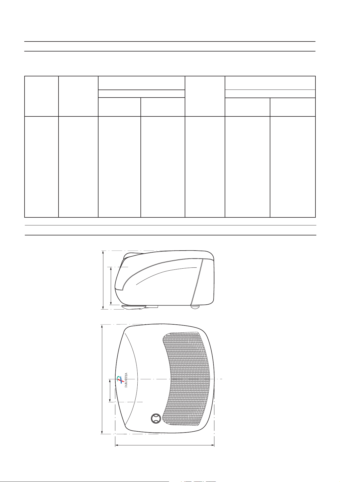
B PROJECTION DISTANCES
Follow the table below to determine the optimal projection distance (between the screen and the center of the lens). This will help
you to obtain the desired screen size.
Screen Screen Screen
size width width
Projection distance Projection distance
4/3 16/9
(diagonal) min max min max
in. m in. m ft. in. m ft. in. m in. m ft. in. m ft. in.
50" 1.0 40" 2.4 8' 0" 3.4 11' 0" 1.1 44" 2.0 6' 6" 2.7 9' 0"
60" 1.2 48" 2.9 9' 7" 4.0 13' 2" 1.3 52" 2.4 7' 10" 3.3 10' 9"
70" 1.4 56" 3.4 11' 2" 4.7 15' 7" 1.6 61" 2.8 9' 1" 3.8 12' 7"
80" 1.6 64" 3.9 12' 6" 5.4 17' 7" 1.8 70" 3.2 10' 5" 4.4 14' 4"
90" 1.8 72" 4.4 14' 4" 6.0 19' 9" 2.0 78" 3.6 11' 9" 4.9 16' 2"
100" 2.0 80" 4.9 16' 0" 6.7 22' 0" 2.2 87" 4.0 13' 1" 5.5 17' 11"
120" 2.4 96" 5.8 19' 2" 8.0 26' 5" 2.7 105" 4.8 15' 8" 6.6 21' 7"
150" 3.1 120" 7.3 23' 11" 10.1 33' 0" 3.3 131" 6.0 19' 7" 8.2 26' 11"
180" 3.7 144" 8.8 28' 9" 12.1 39' 7" 4.0 157" 7.2 23' 6" 9.9 32' 4"
200" 4.1 160" 9.7 31' 11" 13.4 44' 0" 4.4 174" 8.0 26' 1" 11.0 35' 11"
220" 4.5 176'” 10.7 35' 1" - - - 4.9 192" 8.8 28' 9" 12.0 39' 6"
250" 5.1 200" 12.2 39' 11" - - - 5.5 218" 9.9 32' 7" 13.7 44' 11"
C DIMENSIONS
)
7/8
174 (6-
102 (4)
)
7/8
)
352 (13-
15/16
74 (2-
318 (12-
20
1/2
)
unit: mm (inches)
 Loading...